eP01-07 sequential function chart RC1012 - Siemensw3.siemens.com/mcms/sce/de/fortbildungen/... ·...
41
Industry Automation and Drive Technologies - SCE TIA Training Manual Page 1 of 41 Module P01_07 Status: 12/2010 PCS 7 for Universities SEQUENTIAL FUNCTION CHART OBJECTIVE The students will be able to successfully implement sequential controls using step sequences. The students understand the structure and effect of step sequences, and are introduced to corresponding design methods. Knowledge about operating modes and protective measures is expanded for sequential controls. The students understand the interaction between the programs for basic automation and the sequential controls. They know how to generate sequential controls in PCS7. THEORY IN SHORT Sequential controls allow for processing sequential and parallel operations in a mode that is discrete with respect to time or events. They are used to coordinate different continuous functions as well as controlling complex process sequences. Depending on defined states or events, operating and mode changes are generated in the existing logic control systems and as a result, the desired sequential performance is implemented. They are implemented through one or several step sequences (in English: sequential function charts). A step sequence is the alternating sequence of steps that trigger certain actions respectively, and transitions that cause a step to change into another one as soon as the corresponding step enabling condition is met. Each step sequence has exactly one start step and one end step and in addition any number of intermediate steps that are connected respectively through oriented edges by means of interposed transitions. The diagrams may also generate feedback through loops within the step sequence. They also can include parallel or alternative branches. However, in this case it has to be ensured during the design that the sequence does not contain segments that are unsafe or unavailable. To design sequential controls, particularly the formal design methods of state diagrams or Petri’s networks are available. State diagrams are easily learned, make automatic error diagnosis possible and can be converted without a problem into many existing programming languages for sequence controls. However, designing parallel structures is not possible, since state diagrams have only exactly one state. Petri’s networks are considerably more complex and more demanding mathematically. But all structures that are permitted in sequential controls can be modeled and extensively analyzed. Thus, required control properties can be proven formally. Likewise, Petri’s networks allow for no-problem implementation in sequential controls. Sequential controls parameterize and activate lower level logical control systems by setting corresponding global control signals. These control signals can have a brief or a lasting, a direct or a delayed effect. Sequential controls as well as logical control systems have to support different operating modes. Particularly manual control of the transitions and temporary or permanent interruptions of the process sequences has to be possible In addition, process specific protective functions are implemented with sequence controls. In PCS7 , sequence controls are implemented with Sequential Function Charts (SFC) . SFCs provide for efficient operating mode management, high controllability through several switching modes as well as extensive parameterizability through different sequence options. The SFCs and CFCs interact and are linked in PCS7 by means of process variables and control variables. The interactive behavior can also be controlled in detail.
Transcript of eP01-07 sequential function chart RC1012 - Siemensw3.siemens.com/mcms/sce/de/fortbildungen/... ·...

Industry Automation and Drive Technologies - SCE
TIA Training Manual Page 1 of 41 Module P01_07 Status: 12/2010 PCS 7 for Universities
SEQUENTIAL FUNCTION CHART
OBJECTIVE
The students will be able to successfully implement sequential controls using step sequences. The students understand the structure and effect of step sequences, and are introduced to corresponding design methods. Knowledge about operating modes and protective measures is expanded for sequential controls. The students understand the interaction between the programs for basic automation and the sequential controls. They know how to generate sequential controls in PCS7.
THEORY IN SHORT
Sequential controls allow for processing sequential and parallel operations in a mode that is discrete with respect to time or events. They are used to coordinate different continuous functions as well as controlling complex process sequences. Depending on defined states or events, operating and mode changes are generated in the existing logic control systems and as a result, the desired sequential performance is implemented. They are implemented through one or several step sequences (in English: sequential function charts).
A step sequence is the alternating sequence of steps that trigger certain actions respectively, and transitions that cause a step to change into another one as soon as the corresponding step enabling condition is met. Each step sequence has exactly one start step and one end step and in addition any number of intermediate steps that are connected respectively through oriented edges by means of interposed transitions. The diagrams may also generate feedback through loops within the step sequence. They also can include parallel or alternative branches. However, in this case it has to be ensured during the design that the sequence does not contain segments that are unsafe or unavailable.
To design sequential controls, particularly the formal design methods of state diagrams or Petri’s networks are available. State diagrams are easily learned, make automatic error diagnosis possible and can be converted without a problem into many existing programming languages for sequence controls. However, designing parallel structures is not possible, since state diagrams have only exactly one state.
Petri’s networks are considerably more complex and more demanding mathematically. But all structures that are permitted in sequential controls can be modeled and extensively analyzed. Thus, required control properties can be proven formally. Likewise, Petri’s networks allow for no-problem implementation in sequential controls.
Sequential controls parameterize and activate lower level logical control systems by setting corresponding global control signals. These control signals can have a brief or a lasting, a direct or a delayed effect. Sequential controls as well as logical control systems have to support different operating modes. Particularly manual control of the transitions and temporary or permanent interruptions of the process sequences has to be possible In addition, process specific protective functions are implemented with sequence controls.
In PCS7, sequence controls are implemented with Sequential Function Charts (SFC). SFCs provide for efficient operating mode management, high controllability through several switching modes as well as extensive parameterizability through different sequence options. The SFCs and CFCs interact and are linked in PCS7 by means of process variables and control variables. The interactive behavior can also be controlled in detail.

Industry Automation and Drive Technologies - SCE
TIA Training Manual Page 2 of 41 Module P01_07 Status: 12/2010 PCS 7 for Universities
THEORY
CONTINUOUS AND SEQUENTIAL CONTROLS
Within the scope of basic automation, different logic control systems are developed that implement a limited, clearly defined function. The functions continuously process input signals and generate corresponding output signals. By means of different control signals, the functions can also be activated and parameterized. To implement complex process sequences -for example, manufacturing recipes for products- it is necessary to coordinate the different functions and to activate them at the right time with the correct parameters. This task can be handled using sequential controls.
Sequential controls make step by step, event-discrete processing of sequential and parallel operations possible using step sequences. Depending on defined states or events, they generate operating and mode changes in the existing logic control systems and thus implement the desired sequential behavior. Step sequences are also referred to as sequential function charts.
STRUCTURE OF STEP SEQUENCES
A step sequence is the alternating sequence of steps and transitions. The individual steps activate certain actions. The transitions control the change from one step to the next.
The first step of a step sequence is referred to as the start step. It is the unique entry point in the sequence and is always executed. The last step in a step sequence is correspondingly referred to as the end step. It is the only step in the sequence that does not have a sequence transition. After the end step is processed, the step sequence is terminated, or processing starts anew. The latter case is also referred to as sequence loop.
Steps and transitions are connected to each other with oriented diagrams. It is possible to connect a step with several sequential transitions; the reverse is possible also. A transition is enabled if all series connected steps are active and the step enabling condition is met. In this case, first the immediately preceding steps are deactivated and then the immediate subsequent steps are activated.
The simplest form of a step sequence is the unbranched sequence. Each step is followed by exactly one transition, and the transition in turn by exactly one subsequent step. This implements a purely sequential process run. Figure 1 shows the corresponding graphic basic elements.
Figure 1: Basic elements of sequential function charts
S 1
S 2
t 1
Step 1(Start step)
Transition 1
Step 2

Industry Automation and Drive Technologies - SCE
TIA Training Manual Page 3 of 41 Module P01_07 Status: 12/2010 PCS 7 for Universities
Loops within the step sequence occur when by sequencing several steps a cyclical run within a sequence is possible. The sequence loop represents a special case of a loop where all steps are run cyclically.
Another option for structuring step sequences is jumps. When a jump mark is reached, processing continues with the step to which the jump mark points. Jumps within the step sequence can also result in loops. Since such a structure is difficult to follow, jumps should be dispensed with if possible.
In many cases it is necessary from the process view to respond differently to different events when the program is executed. This structure is referred to as alternative branching. The step is linked with each possible subsequent step by means of its own transition. To ensure that at any time at most one of these transitions is enabled (and the branches are actually alternative), the transitions should be mutually locked or clearly prioritized. Otherwise, in most control systems the transitions are evaluated from left to right, and the first transitions whose step enabling condition is met is enabled.
Figure 2 shows, in principle, the structure of alternative branching with two branches. It is represented by bordering horizontal single lines with protruding ends. As can be seen, the alternative branches always start and end with transitions.
Figure 2: Alternative and parallel branches
It is often required that after a step, several subsequent steps are to be processed simultaneously. In this case, the initial step has one transition exactly that activates several subsequent steps at the same time. We call this structure parallel branching. The subsequent steps of the individual branches are processed independent of each other and are then merged again. All branches end in a joint transition. Only after all branches are processed completely and the step enabling condition for the subsequent transition is met is it possible to activate the joint subsequent step.
Figure 2 also shows the sequence of a parallel branch with two branches. They are represented with bordering horizontal double lines and protruding ends. As can be seen, the parallel branches always start and end with actions.
S 1
t 1
t 3
S 4
t 2
S 2 S 3
t 4
S 1
t 1
t 2
S 4
S 2 S 3
Alternative branch Parallel branch

Industry Automation and Drive Technologies - SCE
TIA Training Manual Page 4 of 41 Module P01_07 Status: 12/2010 PCS 7 for Universities
A particular control engineering problem is the possibility to generate -by unfavorably using jumps and branches- faulty step sequences. We are distinguishing three possible cases.
– Uncertain sequence: A step sequence contains a structure whose availability is not ensured through the defined sequential performance.
– Partially stuck: A step sequence contains an internal loop that is not exited. Although the steps within this loop are executed, the steps outside the loop are not. This makes parts of step sequence unavailable.
– Totally stuck: A step sequence contains a structure for which no permissible step enabling condition exists. In this case, the step sequence remains permanently in one state and all other steps are unavailable.
Such structures are not permitted in step sequences and have to be excluded with corresponding design methods. Figure 3 shows examples of two step sequences with impermissible structures.
In the left sequence we can’t ensure that Step S6 is available since the alternative branch after Step S3 prevents -when transition t3 is enabled- that the parallel branch is merged again in transition t4. For that reason, this sequence is uncertain. The right sequence, on the other hand, is executed exactly once and then stops at Step S4. Since Step S2 is not active in this state, the parallel branch can no longer be merged in transition t3. It is totally stuck; Step S5 is unavailable.
Figure 3: Uncertain and illegal structures
S 1
t 1
S 2 S 3
t 2
S 4
t 3
S 5
t 5t 4
S 6
t 6
S 7
t 7
Uncertain structure Illegal structure
S 1
t 1
S 2 S 3
t 2
S 4
t 3
S 5
t 4
Industry Automation and Drive Technologies - SCE
TIA Training Manual Page 5 of 41 Module P01_07 Status: 12/2010 PCS 7 for Universities
DESIGN OF SEQUENCE CONTROLS
There are numerous formal design methods for sequence controls. In practice, however, particularly the state diagrams and Petri’s network have proven themselves.
A state diagram is a connected, oriented diagram. States are represented as circles and the state transitions as arrows that connect exactly two states. In a state diagram, always exactly one state is active at a time. The states can be linked to certain actions. A certain sequence performance can be assigned to these actions. They can be performed once when entering the state or when leaving it, or cyclically as long as the state is active. State transitions can be subject to transition conditions.
State diagrams can be arranged hierarchically, and linked to each other. State diagrams are considered easy to learn and make automatic error diagnosis possible -for example, through pair, time or state monitoring. They can be converted into many existing programming languages for sequence controls, without a problem.
Petri’s networks are particularly suitable for modeling concurrent processes. Petri’s network consists of locations and transitions that are linked to each other with oriented edges. This generates an oriented diagram also. A location is represented as a circle, a transition as a rectangle (often also reduced to a cross bar). Active locations are identified with labels which are represented by a dot within the circle for the corresponding location.
In contrast to function diagrams, in Petri’s network the state is determined by the number of active locations in the entire network. The dynamics of the system is modeled by the movement of the labels within the network. The significance of the locations and transitions for the modeled process (i.e., the semantics of Petri’s network) is not defined and has to be specified depending on the application case. Petri’s networks whose semantics is specified are referred to as interpreted Petri’s networks (IPN). For the control design, control engineering interpreted Petri’s networks (CIPN) are used as a rule.
Petri’s networks can be extensively examined analytically. They also permit the conversion into existing programming languages for sequence controls without a problem. There are numerous expansions for Petri’s networks that are optimized for certain application cases respectively, or permit a more detailed modeling of the process. For that reason, Petri’s networks can become quite complicated which makes them rather demanding as design models. Because of their structural similarity to step sequences and the option of modeling parallel sequences, Petri’s networks offer clear advantages, however.
Which design method is used depends ultimately on the requirements of the design task as well as on the developer’s preference. For additional information, we refer to the pertinent technical literature.
INTERACTION OF SEQUENCE CONTROLS AND LOGIC CONTROL SYSTEMS
As described above, certain actions can be assigned to each step in step sequence. Generally, these actions consist of the parameter assignment and the activation of logic control systems. To this end, corresponding control signals are set.
Process and control signals used by step sequences have to be declared globally so that they are <<available equally? something missing in original>> to the programs of the sequence and logic controls. Usually, the signals are contained in a symbol table.
Control signals always are effective as long as the corresponding step is active. To implement more complex function sequences, it is possible to vary the processing of a control signal itself (latching or non-latching, delayed or limited).
Usually, process specific functions are implemented with sequence controls, while logic controls implement all device specific functions.

Industry Automation and Drive Technologies - SCE
TIA Training Manual Page 6 of 41 Module P01_07 Status: 12/2010 PCS 7 for Universities
PROTECTION FUNCTIONS AND OPERATING MODES IN SEQUENCE CONTROLS
Just as for the individual drive functions, adequate protection functions and operating modes have to be implemented for sequence controls. It has to be possible to operate sequence controls manually if there is a fault. To this end, corresponding operating modes have to be provided for in the control.
– Automatic mode: The action of the step sequence is executed if the preceding transition is enabled.
– Manual mode: The operator triggers the action of step sequence, even if the preceding transition is not enabled.
– Mixed mode: The action of the step sequence is executed if the preceding transition is enabled, or the operator triggered it. As an alternative, operator activation as well as enabling the preceding transition may be required.
The manual mode prevents that the sequence control may be permanently blocked because of a fault. The mixed mode allows for the manual interruption of the sequence for testing or commissioning. The step enabling conditions of all transitions of the sequence control have to be expanded accordingly.
Step sequences have to be able to react to faults in the controlled devices. To this end, continuous fault monitoring is required. It recognizes and signals faults in the controlled devices. It makes automated safety of the plant possible by stopping the step sequence automatically if there is a fault. In addition, it has to be possible for the operator to stop and cancel the step sequence if there is a fault.
In both cases corresponding protection functions have to be activated to take the plant to a safe state. If a sequence is stopped, it has to be ensured that it can be continued safely and in a way that is permissible regarding process engineering, even if the interruption was of a longer duration. In the sequence controls, process specific protection functions are implemented, such as sequential locking of several devices if there is a fault in the process.
SEQUENCE CONTROLS IN PCS7
In PCS7, sequence controls are implemented with Sequential Function Charts (SFC). They contain the step sequences and define their sequence topology, the conditions for the transitions and the actions of the steps. It is possible to define and prioritize the start conditions and the sequence characteristics separately for each step sequence. In addition, the preprocessing and post-processing steps can be defined that are executed once before or after processing the step sequence.
Operating Modes and Switching Modes The performance of a sequence control in PCS7 depends on the following: the selected operating mode, the specified switching mode, its current operating mode, and the sequence options. Two different operating modes can be selected for sequence controls:
– Auto: The program controls the sequence.
– Manual: The operator controls the sequence through commands, or by changing the sequence options.
In the manual mode, the following commands are available to the operator: Start, Stop, Halt, Exit, Cancel, Continue, Restart Reset and Error, to operate the sequence control manually. Depending on the selected operating mode, the behavior of a step sequence can be controlled through different switching modes when further switching active steps to the subsequent steps.
– Switching Mode T: The sequence control is running process controlled; i.e., automatically. If a transition is enabled, the preceding steps are deactivated and the subsequent steps are activated. (T = transactions)
– Switching Mode O: The sequence control is running operator controlled; i.e., manually. The transition is enabled by an operator command. To this end, each

Industry Automation and Drive Technologies - SCE
TIA Training Manual Page 7 of 41 Module P01_07 Status: 12/2010 PCS 7 for Universities
subsequent transition of an active step automatically sets an operator prompt (O = Operator).
– Switching Mode T or O: The sequence control is running process controlled or operator controlled. The transition is enabled either through an operator command or a step enabling condition that was met.
– Switching Mode T and O: The sequence control is running process controlled and operator controlled. The transition is enabled only based on an operator command and if the step enabling condition is met.
– Switching Mode T/T and O: In this switching mode we can specify for each step individually whether the sequence is controlled by the process or the operator. In the test mode, this allows for defining stop points in the sequence control (T/T = Test Transactions)
In the operating mode Auto, only the switching modes T and T/T and O can be selected. The operating mode of the sequence control indicates the current state in the sequence and the resulting performance. A corresponding operating mode logic defines the possible modes, the permissible transitions between the modes as well as the transitional conditions for a mode change. PCS7 defines a separate operating mode logic for sequence controls and for step sequences respectively. It is possible to run step sequences depending on the mode of the sequence control.
Sequence Options
By using sequence options, it is possible to control the execution time performance of sequence controls. For example, we can specify whether a sequence control is processed once or cyclically (option cyclical mode) or whether the actions of the active step are actually performed (option command output). In addition, time monitoring for the individual steps of a step sequence can be activated which signals a step error if there is a timeout (option time monitoring).
Interaction Performance In the PCS7, CFCs and SFCs interact by means of process values and control values. These values are linked by means of the desired signals either from the global symbol table or by entering the absolute signal address. Controlling the processing of the control signals is possible by means of the SFC characteristics. In the SFC Library, the PCS7 makes available preassembled step sequences for different standard scenarios. These templates can be used and adapted to current projects.
LITERATURE
[1] Seitz, M. (2008): Speicherprogrammierbare Steuerungen. Hanser Fachbuchverlag (Programmable Logic Controllers. Hanser Technical Publications)
[2] Wellenreuther, G. and Zastrow, D. (2002): Automatisieren mit SPS: Theorie und Praxis. Vieweg+Teubner (Automating with PLC. Theory and Practice. Vieweg+Teubner Publishers)
[3] Uhlig, R. (2005): SPS - Modellbasierter Steuerungsentwurf für die Praxis: Modellierungsmethoden aus der Informatik in der Automatisierungstechnik. Oldenbourg Industrieverlag (Model Based Control Design in Practice: Modeling Methods from Computer Science in Automation Engineering. Oldenbourg Industrial Publishers)
[4] Siemens (2009): Process Control System PCS 7: SFC for SIMATIC S7.

Industry Automation and Drive Technologies - SCE
TIA Training Manual Page 8 of 41 Module P01_07 Status: 12/2010 PCS 7 for Universities
STEP BY STEP INSTRUCTIONS
TASK
Based on the recipe in the chapter 'Process Description’ we are setting up and programming an SFC step sequence.
For this chapter, we reduced the recipe to the following sequence:
1. First, 350ml are to be drained from educt tank =SCE.A1.T1-B003 to reactor =SCE.A1.T2-R001.
2. When reactor =SCE.A1.T2-R001 is filled, the liquid it contains is to be heated to 25°C and the stirrer is to be switched on.
3. When the temperature of the liquid in reactor =SCE.A1.T2-R001 has reached 25°C, this liquid in this reactor =SCE.A1.T2-R001 is to be stirred another 10 seconds at 25°C.
4. Now, the liquid in reactor =SCE.A1.T2-R001 is to be heated to 28°C with the stirrer being switched on.
5. When the temperature of the liquid in reactor =SCE.A1.T2-R001 has reached 28°C, this liquid is then to be drained into product tank =SCE.A1.T3-B001.
OBJECTIVE
In this chapter, the student learns the following:
– Setting up and editing SFC step sequences
– Establishing logic operations between SFC step sequences and CFCs
– Establishing logic operations between SFC step sequences and the operands in the symbol table
– Testing sequence step programs

Industry Automation and Drive Technologies - SCE
TIA Training Manual Page 9 of 41 Module P01_07 Status: 12/2010 PCS 7 for Universities
PROGRAMMING
1. To start, we are setting up a new SFC in the plant view in the folder ’A1_multipurpose_ plant’.
( A1_multipurpose_pant Insert New Object SFC)

Industry Automation and Drive Technologies - SCE
TIA Training Manual Page 10 of 41 Module P01_07 Status: 12/2010 PCS 7 for Universities
2. Next, we are selecting the SFC properties.
( SFC(1) Object Properties)
3. Under General, we change the name to ’SFC_Produkt01’.
( General SFC_Produkt01)

Industry Automation and Drive Technologies - SCE
TIA Training Manual Page 11 of 41 Module P01_07 Status: 12/2010 PCS 7 for Universities
4. We are keeping the operating parameters; they can be changed later in the online mode ( AS Operating parameters)
5. Regarding the tab OS it is important that the checkmark is set so that the SFC will be available later in visualization.
( OS Transfer chart to the OS for visualization)
Industry Automation and Drive Technologies - SCE
TIA Training Manual Page 12 of 41 Module P01_07 Status: 12/2010 PCS 7 for Universities
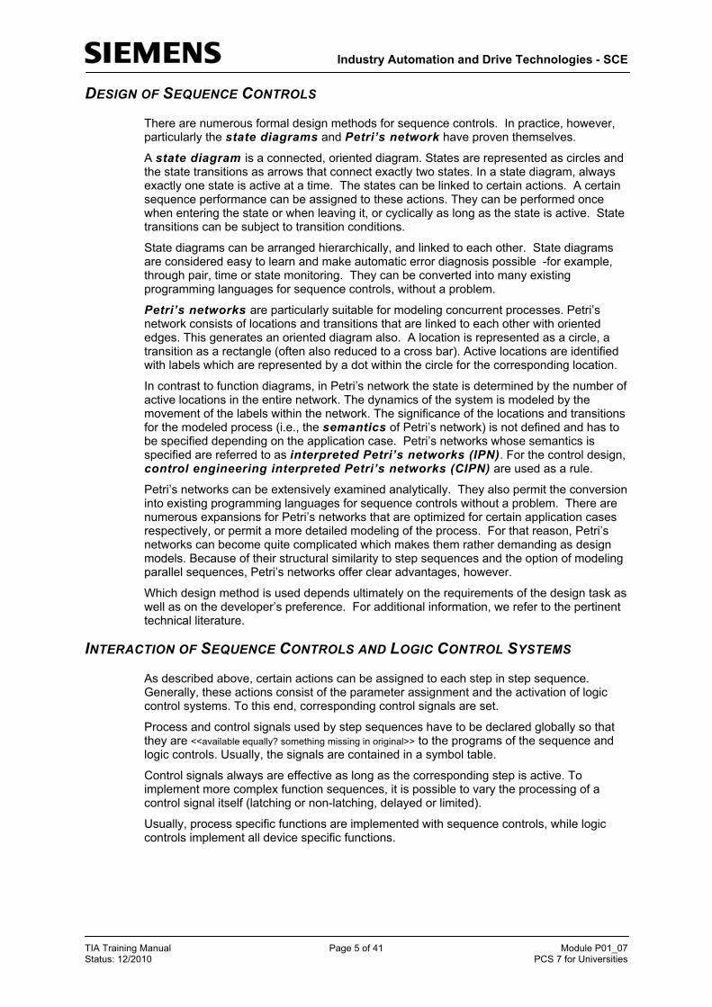
6. Under the tab Version, we accept all parameters with OK.
( Version OK)
7. Now, with a double click, we open the step sequence ’SFC_Produkt01’ in the SIMATIC Manager. ( SFC_product01)

Industry Automation and Drive Technologies - SCE
TIA Training Manual Page 13 of 41 Module P01_07 Status: 12/2010 PCS 7 for Universities
8. In the SFC editor, it is now possible to set up the sequence control with the following symbols from the tool bar.
Button Switch on Select
Button Insert Step and Transition
Button Insert parallel branch
Button Insert alternative branch
Button Insert loop
Button Insert jump
Button Insert text field

Industry Automation and Drive Technologies - SCE
TIA Training Manual Page 14 of 41 Module P01_07 Status: 12/2010 PCS 7 for Universities
9. We need additional steps and transitions for our task. To insert both, we select the
button and then select the location where we want to insert them. ( )
Industry Automation and Drive Technologies - SCE
TIA Training Manual Page 15 of 41 Module P01_07 Status: 12/2010 PCS 7 for Universities
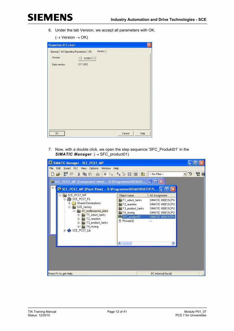
10. After we inserted five steps and transitions in this way, we click on the symbol to
edit normally again. ( )
Note: Step and transition numbering is of no impotance for the sequence in which the step sequence is processed.
!

Industry Automation and Drive Technologies - SCE
TIA Training Manual Page 16 of 41 Module P01_07 Status: 12/2010 PCS 7 for Universities
11. Now, we first want to be able to change the properties of a step. Right click on the step and then select Object Properties. ( 3 Object Properties)
12. For greater clarity, each step is assigned a name in the object properties. ( eductB003toR001 Close)

Industry Automation and Drive Technologies - SCE
TIA Training Manual Page 17 of 41 Module P01_07 Status: 12/2010 PCS 7 for Universities
13. As for the steps, for the transitions also the properties have to be changed. Right click on the transition and then select Object Properties. ( 1 Object Properties)
14. Here also, first only the name is changed. ( Init_OK Close)

Industry Automation and Drive Technologies - SCE
TIA Training Manual Page 18 of 41 Module P01_07 Status: 12/2010 PCS 7 for Universities
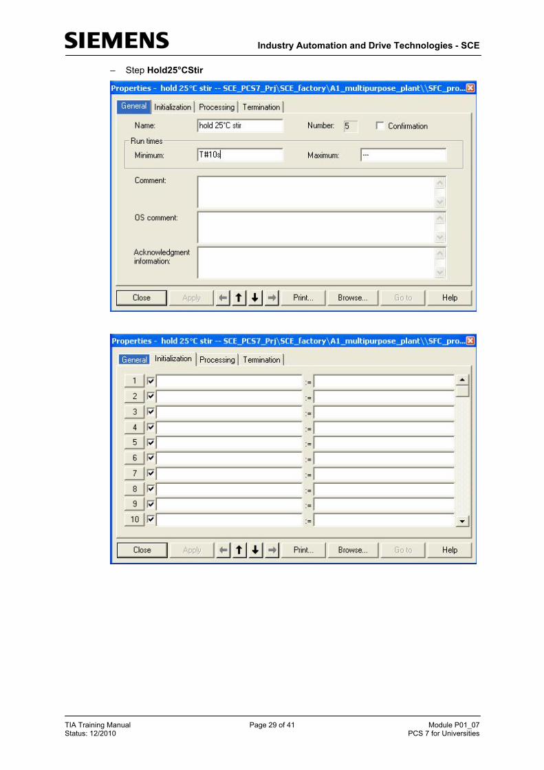
15. Repeat the previous steps until our SFC looks like this. It is important to enter at the step ’hold 25°C stir’ also the minimum execution time of 10 seconds. ( T#10s)

Industry Automation and Drive Technologies - SCE
TIA Training Manual Page 19 of 41 Module P01_07 Status: 12/2010 PCS 7 for Universities
16. Now we have to implement the actual function of the step sequence. We start by double clicking on the step ’START’. ( START)
17. To establish logic operations with the CFCs or symbols, we are selecting the first field and then click on ’Browse’. ( Browse)

Industry Automation and Drive Technologies - SCE
TIA Training Manual Page 20 of 41 Module P01_07 Status: 12/2010 PCS 7 for Universities
18. Then, in a selection window in the familiar clearly laid out plant view we select the connection of a desired block.
( SCE_factory A1_multipurpose_plant T1_educt_tanks A1T1S003 A1T1S003 Pump_A1T1S003 AUT_ON_OP)

Industry Automation and Drive Technologies - SCE
TIA Training Manual Page 21 of 41 Module P01_07 Status: 12/2010 PCS 7 for Universities
19. On the right side, this parameter can be assigned either the value of another parameter again from the plant view or, as here, simply a constant. ( Auto Close)
20. Now we are editing the next step ’heat 25°C stir’ by first opening it with a double click. ( heat 25°C stir)

Industry Automation and Drive Technologies - SCE
TIA Training Manual Page 22 of 41 Module P01_07 Status: 12/2010 PCS 7 for Universities
21. To establish connections, we highlight the first field and then click on ’Browse’. ( Browse)
22. Next, in the selection window in the plant view, we select the matching connection in the plant view. ( SCE_factory A1_multipurpose_plant T2_reaction A1T2T001 A1T2T001 PIDTemp_A1T2T001 SP_EXT)

Industry Automation and Drive Technologies - SCE
TIA Training Manual Page 23 of 41 Module P01_07 Status: 12/2010 PCS 7 for Universities
23. On the right, again a constant is assigned to this parameter. ( 25.0 Close)
24. Now we specify the step enabling conditions. To do this, we open the first transition by selecting it with a double click.
( Init_OK)

Industry Automation and Drive Technologies - SCE
TIA Training Manual Page 24 of 41 Module P01_07 Status: 12/2010 PCS 7 for Universities
25. To again establish logic operations, we highlight the first field and then click on ’Browse’. ( Browse)
26. This time, we select an operand under Symbol.
( Symbol A1.A1H001.HS+-.START)

Industry Automation and Drive Technologies - SCE
TIA Training Manual Page 25 of 41 Module P01_07 Status: 12/2010 PCS 7 for Universities
27. To the right, we again enter a value, and in the center we specify the type of operation. Here, we are querying the equality of the values. ( TRUE = Close)
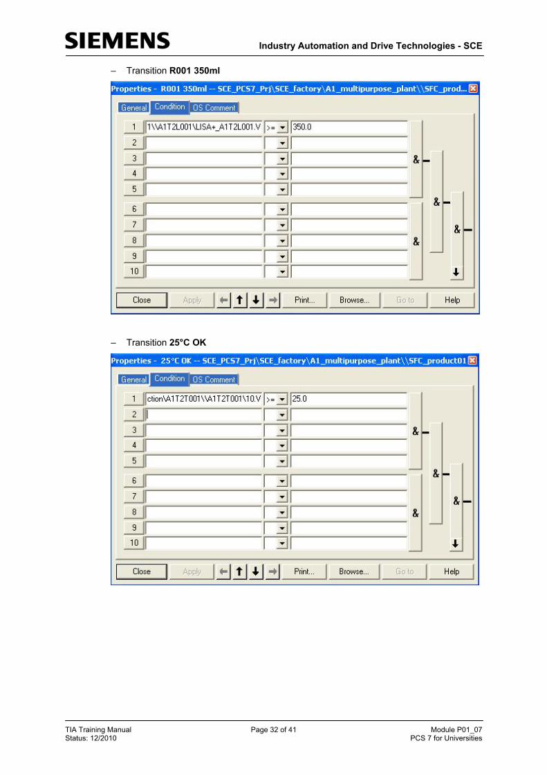
28. As the next step enabling condition we open ’R001 350ml’ with a double click.
( R001 350ml)

Industry Automation and Drive Technologies - SCE
TIA Training Manual Page 26 of 41 Module P01_07 Status: 12/2010 PCS 7 for Universities
29. For the operations, we again highlight the first field and then click on ’Browse’. ( Browse)
30. This time, we select a connection in the selection window in the plant view. ( SCE_factory A1_multipurpose_plant T2_reaction A1T2L001 A1T2L001 LISA+_A1T2T001 V)

Industry Automation and Drive Technologies - SCE
TIA Training Manual Page 27 of 41 Module P01_07 Status: 12/2010 PCS 7 for Universities
31. To the right, we enter a value and in the center, we again specify the comparator type. Here, we query for larger or equal to.
( 350.0 >= Close)
32. Just as shown in the previous steps, we now program the entire step sequence. In the result, the steps of the completed step sequence should look like this:
– Step START

Industry Automation and Drive Technologies - SCE
TIA Training Manual Page 28 of 41 Module P01_07 Status: 12/2010 PCS 7 for Universities
– Step EductB003inR001
– Step Heat25°CStir
Industry Automation and Drive Technologies - SCE
TIA Training Manual Page 29 of 41 Module P01_07 Status: 12/2010 PCS 7 for Universities
– Step Hold25°CStir

Industry Automation and Drive Technologies - SCE
TIA Training Manual Page 30 of 41 Module P01_07 Status: 12/2010 PCS 7 for Universities
– Step heat 28°C stir
– Step R001inProdB001

Industry Automation and Drive Technologies - SCE
TIA Training Manual Page 31 of 41 Module P01_07 Status: 12/2010 PCS 7 for Universities
– Step END
The transitions of the completed step sequence look like this:
– Transition Init_OK
Industry Automation and Drive Technologies - SCE
TIA Training Manual Page 32 of 41 Module P01_07 Status: 12/2010 PCS 7 for Universities
– Transition R001 350ml
– Transition 25°C OK
Industry Automation and Drive Technologies - SCE
TIA Training Manual Page 33 of 41 Module P01_07 Status: 12/2010 PCS 7 for Universities
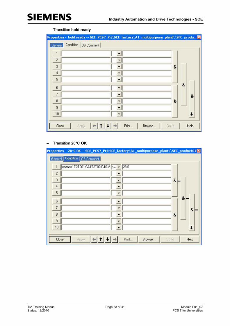
– Transition hold ready
– Transition 28°C OK

Industry Automation and Drive Technologies - SCE
TIA Training Manual Page 34 of 41 Module P01_07 Status: 12/2010 PCS 7 for Universities
– Transition ready
33. Before we can test our program with the step sequence in the SFC, we have to again compile and download the objects from the component view.
( SIMATIC Manager Component view SIMATIC 400(1) PLC Compile and Download Objects)

Industry Automation and Drive Technologies - SCE
TIA Training Manual Page 35 of 41 Module P01_07 Status: 12/2010 PCS 7 for Universities
34. In the tool for compiling and downloading, we now check the settings for the charts. ( Charts Settings for Compilation/Download Edit)
35. For the scope during compiling we select ’Entire program’ and have the module drivers generated once more.
(Compile Charts as Program Scope: Entire program Generate module drivers)

Industry Automation and Drive Technologies - SCE
TIA Training Manual Page 36 of 41 Module P01_07 Status: 12/2010 PCS 7 for Universities
36. We download the entire program also.
(S7 Download Download mode: Entire program Generate module drivers)
Note: Downloading the entire program is possible only if the CPU is in the ’STOP’ mode.
37. After we set the check marks at ’Compile’ and ’Download’, we can start compiling and downloading. ( Charts Compile Download Start)
!
Industry Automation and Drive Technologies - SCE
TIA Training Manual Page 37 of 41 Module P01_07 Status: 12/2010 PCS 7 for Universities
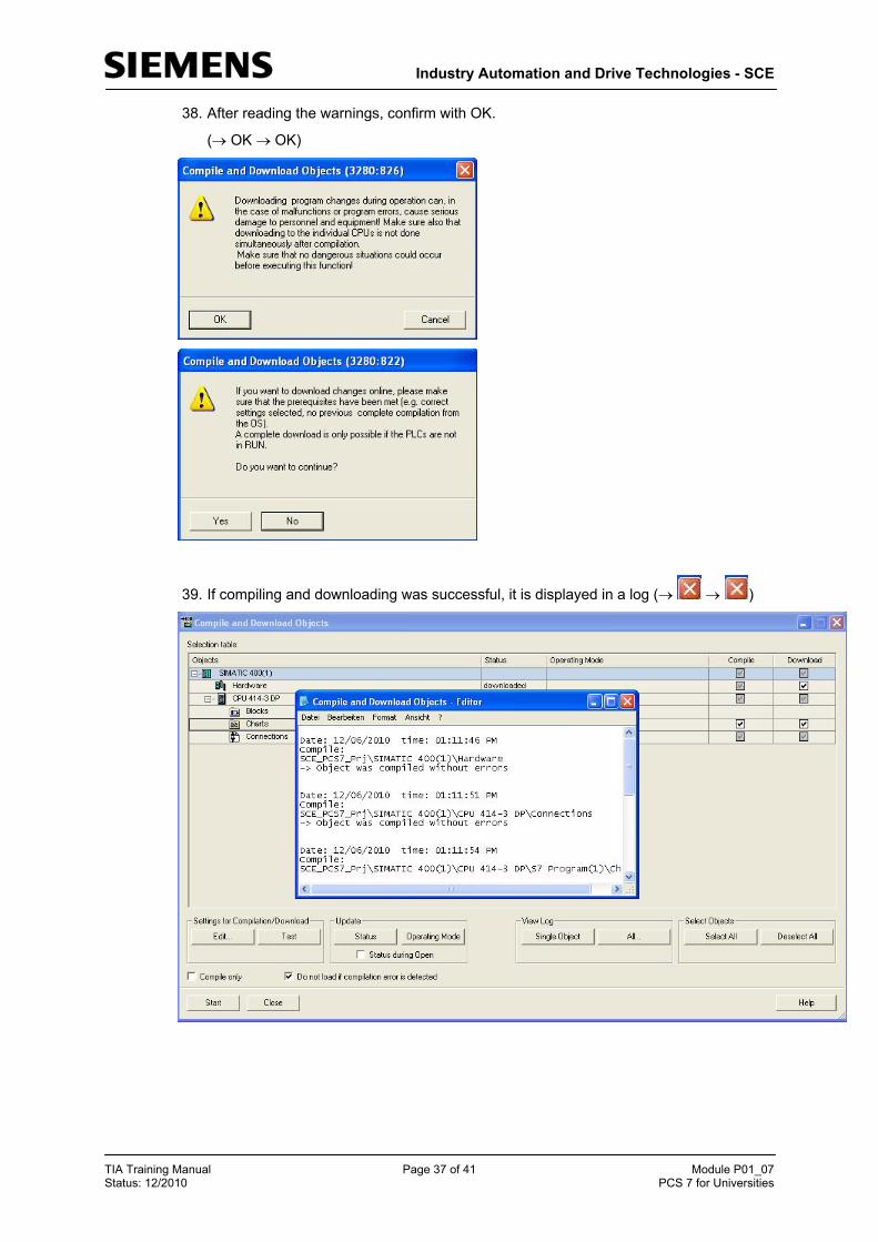
38. After reading the warnings, confirm with OK.
( OK OK)
39. If compiling and downloading was successful, it is displayed in a log ( )

Industry Automation and Drive Technologies - SCE
TIA Training Manual Page 38 of 41 Module P01_07 Status: 12/2010 PCS 7 for Universities
40. We now switch again to our step sequence ’SFC_product01’ to test and watch the
program there. Start the test mode by clicking on the symbol . ( )

Industry Automation and Drive Technologies - SCE
TIA Training Manual Page 39 of 41 Module P01_07 Status: 12/2010 PCS 7 for Universities
41. Now we can watch how the step sequence is processed, and we can also operate it.
For example, our step sequence has to be started by clicking on (
)
Industry Automation and Drive Technologies - SCE
TIA Training Manual Page 40 of 41 Module P01_07 Status: 12/2010 PCS 7 for Universities
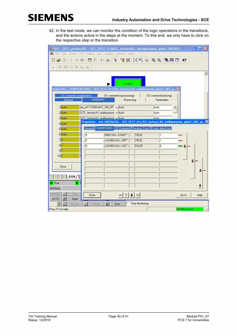
42. In the test mode, we can monitor the condition of the logic operations in the transitions, and the actions active in the steps at the moment. To this end, we only have to click on the respective step or the transition.
Industry Automation and Drive Technologies - SCE
TIA Training Manual Page 41 of 41 Module P01_07 Status: 12/2010 PCS 7 for Universities
EXERCISES
We are going to apply to the exercises what we learned in the theory part and the step by step instructions. We are going to utilize and expand on the existing multi-project provided in the step by step instructions (PCS7_SCE_0107_R1009.zip).
This exercise is intended as a complex exercise, where the technical knowledge presented in the entire Module P01 is repeated. The tasks below are to be an aid to incorporate with Reactor R002 the second line that was missing so far into the project.
TASKS
The following steps are based on the step by step instructions. For each task, the corresponding steps in the instructions can be used as an aid.
1. For the second line, the corresponding plant hierarchy has to be implemented. Set up a folder for each of the individual drive functions listed in Table 1.
2. Implement the individual drive functions in the associated folder of the plant hierarchy. Use the functions that are already implemented from the previous exercises. When you implement the individual drive functions, don’t omit to carry out the required steps for plant safety.
3. Based on the step by step instructions, implement in the SFC step sequence a second line that includes the required steps for Reactor R002. The objective is implementing the recipe according to the process description. In the step by step instructions, all steps in reference to Reactor R001 are already implemented.
Table 1: Required individual drive functions
Name Type
A1T1S001 Motor
A1T1S002 Motor
A1T1X004 Valve
A1T1X005 Valve
A1T2H004 Manual operation
A1T2H005 Manual operation
A1T2H009 Manual operation
A1T2H016 Manual operation
A1T2L002 Measure level
A1T2S002 Motor
A1T2S004 Motor
A1T2X004 Valve
A1T2X005 Valve
A1T2X008 Valve