ENHANCED SOLUTIONS WITH BIOGRAPHY MODERN … · Enhanced solutions with modern structural shapes:...
12
Page 1 of 12 ENHANCED SOLUTIONS WITH MODERN STRUCTURAL SHAPES: EUROPEAN TRENDS FOR COMPOSITE BRIDGES AND SPECIAL STRUCTURES RICCARDO ZANON TONI DEMARCO BIOGRAPHY Riccardo Zanon, S.E., MBA, is Head of Business Development EuroStructures at ArcelorMittal Europe - Long Products, based in Luxembourg. Previously he held positions in the R&D and Technical Advisory Department at ArcelorMittal Europe. He is a graduate of the Technische Universität Dresden (Germany). Toni Demarco, S.E., is Head of Sales & Marketing EuroStructures at ArcelorMittal Europe – Long Products, based in Luxembourg. Previously he held positions in the R&D and Technical Advisory Department at ArcelorMittal Europe. He is a graduate of the Universität Karlsruhe (Germany). SUMMARY In recent years, the European steel fabrication market has experienced a significant transition in terms of standard, practice, and supply chain layout. The key-players in the fabrication and erection of structural steelwork have evolved according to these market changes, and as a result, the landscape of European steel construction looks more homogeneous today than it did before. In addition, numerous interesting and unique applications of modern structural shapes are popping up in designs throughout Europe. Heavy sections are seeing more use in the steel skeleton of high- rise buildings. Broader use of milling technology for the realization of connections has brought forth relevant advantages for detailing. Castellated beam configurations have been revitalized, leading to new design alternatives for architects and engineers. This paper will explore trends in Europe to understand how different requirements from customers have brought forth tenders focusing more on performance and less on prescriptions, and how restructuring of the segment has brought changes in the fabrication and erection practice. In addition, it will review unique design solutions for composite bridges and special structures using modern structural shapes.
Transcript of ENHANCED SOLUTIONS WITH BIOGRAPHY MODERN … · Enhanced solutions with modern structural shapes:...

Page 1 of 12
ENHANCED SOLUTIONS WITH
MODERN STRUCTURAL
SHAPES:
EUROPEAN TRENDS FOR COMPOSITE
BRIDGES AND SPECIAL
STRUCTURES
RICCARDO ZANON
TONI DEMARCO
BIOGRAPHY
Riccardo Zanon, S.E., MBA, is Head of Business Development EuroStructures at ArcelorMittal Europe - Long Products, based in Luxembourg. Previously he held positions in the R&D and Technical Advisory Department at ArcelorMittal Europe. He is a graduate of the Technische Universität Dresden (Germany).
Toni Demarco, S.E., is Head of Sales & Marketing EuroStructures at ArcelorMittal Europe – Long Products, based in Luxembourg. Previously he held positions in the R&D and Technical Advisory Department at ArcelorMittal Europe. He is a graduate of the Universität Karlsruhe (Germany).
SUMMARY
In recent years, the European steel fabrication market has experienced a significant transition in terms of standard, practice, and supply chain layout. The key-players in the fabrication and erection of structural steelwork have
evolved according to these market changes, and as a result, the landscape of European steel construction looks more homogeneous today than it did before.
In addition, numerous interesting and unique applications of modern structural shapes are popping up in designs throughout Europe. Heavy sections are seeing more use in the steel skeleton of high-rise buildings. Broader use of milling technology for the realization of connections has brought forth relevant advantages for detailing. Castellated beam configurations have been revitalized, leading to new design alternatives for architects and engineers. This paper will explore trends in Europe to understand how different requirements from customers have brought forth tenders focusing more on performance and less on prescriptions, and how restructuring of the segment has brought changes in the fabrication and erection practice. In addition, it will review unique design solutions for composite bridges and special structures using modern structural shapes.

Page 2 of 12
Enhanced solutions with modern structural shapes: European trends for composite bridges and special structures
Figure 1: Left: view of rolled section at the rolling mill; Right: view of steel-concrete composite deck with rolled girders
1. TRENDS THROUGH THE STEELWORK PRACTICE
1.1 European Steel Fabrication
The European steel fabrication sector has experienced major changes over the last decade. From the authors’ perspective, some of the main trends to recognize are the following:
- Harmonization of the European structural steel product standard (namely: EN10025). The European standard substitutes national provisions, although specific local recommendations remain in place for special structure owners (e.g. bridges, energy plants or off-shore installations).
- Finalization of the European steel fabrication standard and adoption at the member states level (namely: EN1090). Also in this case, the standard supersedes national provisions concerning steel fabrication, but it may be completed by specific national or application provisions.
- Stepwise introduction of alternative tender formulas to traditional ones, such as Design & Build or Optimize & Build. Increased collaboration during conception is therefore displaced from the tendering party to the contracting party.
For several decades, steel products had been marketed at the European level, so harmonization of the standard has not significantly altered the supply chain layout. Conversely, the steel fabrication market has undergone an integration process at the European level, thereby resulting in an homogeneization of manufacturing techniques and quality standards.
Steelwork usually is preferred in lieu of concrete structures as a result of one major advantage: reduced construction time. A wider choice in tender formulas has stressed competition not only related to material cost budget, but also and even more so related to construction schedule. This has led steel contractors to engage in a “race against time” to tighten up the construction time.
As a consequence, participating in tender for medium and major projects requires increased technical, financial and management capacities. Such effects have consolidated steel construction activities within a smaller group of major steel fabricators. In a standard project management process, fabricators keep core fabrication activities in-house and tend to subcontract fabrication of secondary elements to smaller steel contractors or specialized beam centers. As a result, the gap between major steel fabricators and their smaller competitors has widened but their collaboration has increased.

Page 3 of 12
1.2 Spotlight in the daily practice
From the authors’ point of view, the following
trends are influencing steel fabrication in Europe:
- Increase in process automatization – even if, in some cases, this results in an increase of material usage;
- Stricter requirements concerning geometric and acceptance tolerances, quality controls and in-situ execution; mainly due to increased expectations from designers;
- A more defined distinction between fabricators and erectors, the second typically serving as subcontractor to the first;
- Decrease of bolted connections in favour of welded connections, with greater care necessary in the detailing and execution of welds;
- Welded I-sections in standard grade and common sizes have become a commodity that can be purchased at local steel fabricators; qualified steel fabricators are focusing more on complex finishing (e.g. higher steel grades, exceptional sizes for I-sections, box girders or welded pipes);
- Concerning bridges: decrease in use of weathering steel in favour of protective coatings, mainly for aesthetic reasons;
- Concerning buildings: renewed interest in weathering steel for façade and external architectural elements.
2. TRENDS THROUGH THE SUPPLY CHAIN
2.1 Link from the steel mill to the user
The supply chain has also undergone a significant evolution. In order to achieve material optimization, orders are tailored on a project basis to minimize waste. In this configuration, the role of steel distribution centers has changed to strategic partners.
Some stockists have extended their initial finishing capacities, such as simple cut-and-drill services, therefore becoming so-called “beam finishing centers” Their capacities may even
include complex fabrication, as well as surface treatment facilities.
As a result, steel fabricators have considered subcontracting partial or complete finishing of subassemblies to beam centers without changing the supply chain, as these centers are often the same source where raw material is supplied. The resulting relationship leads to no risk of competition between the parties, as beam centers intervene only at the request of the steel fabricator and the centers provide finishing services on the basis of execution drawings without interferring in steelwork design, contracting or erection.
2.2 Develop synergy through the supply chain
Steel stockists and beam centers have assumed an important role as a partner to the steel fabricator, striving to ensure the fabricator’s competitive advantage as it fulfills project obligations. The mission of stockists’ finishing services and beam centers is to provide the fabricator with the following:
- Additional fabrication capacity, e.g. during peak activity levels;
- Insurance of specific fabrication capability, e.g. cambering, sawing or drilling of heavy structural shapes;
- Creation of optimized logistic solutions, e.g. through reduction of freight cost or lead time.
2.3 Some application examples for heavy shapes
In Europe, subcontracting fabrication to beam centers is common in the following cases:
- Simple finishing of heavy sections (straightening, cambering, cutting, drilling, chamfering, assembling) in the range beyond the fabricator’s capacity (in terms of section height, beam length, piece weight or flange thickness);
- Ready-to-install, simple bridge girder solutions – (e.g. filler beam decks or small-span multi-girder composite decks);
- Tailor-made solutions for specific applications in the building industry (e.g. castellated beams, floor beams for car parks, Slim-Floor beams).

Page 4 of 12
3. USE OF JUMBO SHAPES
3.1 Foreword
Rolled structural shapes (L, I, H, U) were developed at the beginning of the past century, answering the need to simplify shapes built up from plates assembled together by rivets. The advantages in terms of weight savings, fabrication simplification and cost reduction were integral to the acceptance of rolled shapes in every field. Today, the geometric range of available H structural shapes is extensive (beam height 80…1150mm, flange width 50…450mm, flange thickness 4…140mm) with a well-established presence of production sites around the world [3], [4].
In addition to expansion of geometric properties, the development of optimized rolling procedures occurred over several decades. Since the 1990, thermo-mechanical rolling has become a standard for the most advanced plants in Western Europe. In order to enhance the benefits of thermomechanical rolling, the quenching and self-tempering process (QST) was developed specifically for sections with thick flanges. Implementing this innovative procedure, made it possible to economically obtain high steel strengths (up to 485MPa) for heavy sections without the costly addition of alloying elements [8].
3.2 Heavy columns and diagrids
With some delay, but following structural configurations already conceived on the other side of the Atlantic, several high-rise buildings have been built in Europe based on a steel-framed skeleton. In most cases steel has managed to replace the traditional material (reinforced concrete) in this type of structure as a result of advantages concerning the speed of erection and the reliability of the construction, inverting therefore the practice of past decades [7].
Figure 2: Torri Varesine in Mailand (Italy) [10]
Figure 3: Tour D2 in Paris (France) [15]

Page 5 of 12
Figure 4: Standard chamfering of Heavy Jumbo shapes by means of flame cutting [1]
Heavy structural shapes are often used, as in the US, as principal members of a building skeleton. Most tall buildings feature braced frames, with heavy shapes used as gravity columns. A recent example is the Torre Diamante in Mailand, the tallest steel-framed building in Italy [11].
Conversely some buildings use a diagrid structural concept as the main load-carrying mechanism, using heavy sections as members of the façade truss structure. An iconic example of this concept is Tour D2 in Paris.
3.3 Preparation of beam end-connections
Concerning the use of heavy sections, besides the technology of cold sawing and oxycutting, surfacic milling of the ends to create specific member connection types is widespread. The primary advantages of this complex technology are: - Increase in working precision, therefore
decreasing geometric tolerance issues and problems on the jobsite;
- Create specific shapes for optimizing the welding procedure. In particular, more complex shapes than the classical K or V shape may be realized, decreasing the volume of welded material;
Figure 5: Diagonal of outrigger system with a milling connection detail to fit on a thick gusset plate
- Allowance of specific member connection needs, e.g. diagonal connection on gusset plates;
- Minor impact on the metallurgy of the base material when compared to other working technology, such as oxycutting, This is particularly relevant for thick material with high strength;
- Follow severe standard specifications for fatigue design, e.g. in the case of a butt-weld connection thickness change.
The shape of the connection must be analyzed in detail and must comply with relevant welding and joint design standards (e.g. [1], [3]).
Figure 6: Availability of Jumbo structural shapes [14]

Page 6 of 12
5. RAILWAY BRIDGES – FILLER BEAM DECKS 5.1 Structural solution
A filler beam deck is composed of rolled sections, closely spaced and encased with reinforced concrete. In the longitudinal direction the steel girders act composite with the concrete and carry loads along the bridge span; whereas in the transverse direction, rebar ensures the transverse bending resistance of the reinforced concrete. Permanent formwork are foreseen between the lower flanges of the beams. Corrosion protection is needed only on the bottom flanges of the sections, the rest of the steelwork being encased in concrete.
Figure 7: Cross section of a typical railway bridge using filler beam deck [2]
The first formal statement of this structural
typology goes back to Mr. Descubes, chief engineer from the French railways, in the 19th century [1]. The main asset of this solution was its ability to overcome the disadvantages of steel structures of the time (maintenance difficulties, repair and replacement of connecting elements, corrosion protection) for the small span decks. The first projects used rails or H-beams, stiffened with struts, supporting a vault constructed of masonry filled out with non-structural mortar. The key development was to substitute the masonry infills with structural reinforced concrete, ensuring the stability of the steel beams, transverse load repartition, and corrosion protection of the steelwork.
Bridge designs using filler beam decks have seen immediate success for the span range corresponding to road and rail overpasses. Main benefits are elimination of a need to scaffolding,
reduced thickness of the deck, and a relatively simple construction phase. Another important benefit for overpasses on existing tracks is the ability to avoid disruption of traffic during the construction phase. Some later publication of the ’30 already praise this structural typology for its robustness and reliability, showing that it had already used since decades with satisfaction.
Figure 8: Fixing of anti-LTB devices before erection [15]
5.2 Steel fabrication and deck erection
Filler beams are typically fabricated directly at the steel plant. After being cut-to-length, the sections are pre-cambered according to load-bearing requirements, in order to compensate for deformations under self-weight and to ensure the conceived deck shape will be achieved. Holes are drilled in the web to install stabilization systems and transverse reinforcement. Corrosion protection is applied only on the exposed lower flange and the adjacent part of the web.
Figure 9: Erection of filler beams on the construction site [15]

Page 7 of 12
Figure 10: Filler beam deck before concreting [15]
Fully finished beams are transported preferably
by railroad in order to decrease environmental impact and freight costs. Girders with lengths up to 60m have been successfully transported by rail to the jobsite.
Steel elements are typically erected by crane in packages of several beams lifted together directly into their final position on the bearings. Lower reinforcement layer may be installed before erection. After splicing of the main beams, concrete is poured on the deck in several steps. Repositioning of the deck after concreting may be necessary for the correct introduction of load onto supports. 5.3 Advantages of filler beam decks
The main advantages of these construction typologies are the following: - Slenderness: the high-load bearing capacity of
the encased steel beams permits extremely high slenderness ratios (span / construction height) compared to other technologies;
- Reduced traffic disturbance: structural steel is self-supporting and host place for formworks. Linked with the previous advantage, it makes this typology a preferred solution for railway/roadway overpasses;
- Robustness: thanks to compact deck solution, lack of delicate prestressing devices, structural continuity over the whole bridge length;
- Durability: structural steel is very well protected against corrosion, structural concrete is used during the lifetime at a relatively low utilization ratio. Thanks to the minimal amount of welding, fatigue is not an issue.
Figure 11: Slenderness ratio of filler beam decks 5.4 The experience of Bridge owners
Analysis of the heritage of German Railways [9] shows that, of the roughly 31000 existing structures, more than a quarter are filler beam decks. This means that traveling on the German railway network for an hour with a speed of 160 km / h, on average the train rolls 35 decks of this type. The same situation is found in several countries in continental Europe, giving solid foundation to the assumption that the number of filler beam decks in service today on the European rail network exceeds by far 10,000 units.
The main reason for this success is the reliability and robustness of the structural typology: with an average service age of 88 years, it represents the most durable deck typology available (the average lifetime of railway decks is about 60 years). Even more remarkable, a consistent part of these steel beams are nowadays in service for more than 120 years without major issues.
Figure 12: Filler beam deck after completion – side view at high-speed train passage [2]

Page 8 of 12
6. SMALL SPAN BRIDGES - COMPOSITE GIRDERS 6.1 Recent trends for roadway bridges
The use of composite steel structures has gained significant market shares in road bridges across Europe over the last several decades. In the field of medium span bridges (25m – 50m span), the common solution with a concrete plate and downstand steel I-girders often proves to be the most economic solution in design. Twin girder decks offer a simple and effective structural solution. Technical advantages in terms of erection possibilities (launching, crane lifting, assembling), structural efficiency and flexibility in design (curved girders, variable inertia) make steel concrete composite bridges the solution of choice. Nevertheless, in the lower part of this span range (e.g. 25-35m), this typology can sometimes be less economic when compared to prefabricated, pre-stressed concrete solutions. Some of the main reasons for this are:
1. The benefits of lighter structures, resulting in a decrease of self-weight and consequent decrease of design loads, become less important by decreasing the span.
2. Erection by crane lifting of prefabricated elements is quite an easy and cost effective construction method for spans up to 30m and elements weighting up to 40 tons. More complex erection phases are typically not economic, except special construction site constraints.
3. In most cases, the twin-girder concept is not optimized for spans < 30m due to low span / deck width ratio; for these cases the multi-girder concept is more convenient.
In this lower span range it is therefore even more important to take advantage of benefits of composite action between steel and concrete. An optimized solution consists in using prefabricated composite beams, where the steel girder as economic rolled girder is integrated already in the transient phase by a concrete plate, joined longitudinally at concrete cross beams locations in correspondence with the intermediate piers [6].
Figure 13: Market share of different deck typologies in function of the span, France [15]
6.2 Optimization of the cross-section
The geometry of cross sections is optimized for plate girders as a function of the loads and the construction phases, obtaining asymmetrical sections and extremely thin webs. In this manner the utilization of the steel quantities tends to the most efficient consumption.
Using rolled girders, cross-section changes along the axis can be achieved by adding welded plates or hunching the sections at the supports, but in general, the designer has to stick on the geometric properties of the standard rolled products. Due to their maximum beam depth up to 1.2m, it makes sense to use rolled sections for bridges with spans up to 40-45m (slenderness 30). In this range, using the same steel grade, rolled girders may result in being 10 to 30% heavier.
Figure 14: Fabrication of composite bridge girders out of rolled sections – cambering and plate/stud welding [13]

Page 9 of 12
6.3 Choice of the steel grade
In Europe, plate girders for small span bridges are usually constructed in steel grade S355 (comparable to Grade 50). This grade is quite common, available on stock, and implies well known and mastered welding procedures. Using plates in higher steel strength is not common for small span bridges.
Conversely, the use of rolled girders in S460 (comparable to Grade 65) is well established in the European practice and is advantageous for road bridges, as the high strength can lead to weight savings in the design of the structural system. In addition, when high-strength sections are produced using a quenching and self tempering process, the members’ low-carbon content results in improved weldability of the material. As a result of the benefits of weight savings and simplifed fabrication, rolled girders in high steel strength have become a solution of choice for standard small span bridges.
Figure 15: Fully-finished bridge girder on the construction site ready for installation [13]
6.4 Fabrication
In the case of plate girders, besides longitudinal welding for assembling the three plates to the I shape, beam splicing (in the workshop or on the construction site) are required every 12m- 18m.
Rolled sections do not require longitudinal welding to build up the section. They may be manufactured up to 40m length, therefore reducing or even avoiding the splicing of the main beams. In this way, the amount of fabrication is strongly reduced, decreasing cost and improving delivery time. These advantages
can compensate for higher transportation costs, if any, in the cases where the construction site is accessible only by trucks.
Figure 16: Concrete cross beams at abutments and intermediate piers [9]
6.5 Corrosion protection
In Europe most bridges are painted with protective coatings. Weathering steel is used only in some countries in Southern Europe. Therefore, corrosion protection constitutes a relevant part in the budget of steel contractors, as well as for bridge owners.
Rolled sections are in general more “compact” than welded girders: given the same bending resistance, the surface to paint divided by the unity of mass is for rolled girders usually between 15 and 30% less than for welded girders. This decreases the initial cost, as well as every day maintenance operation requiring repainting during the life cycle of the bridge.
Figure 17: Composite bridge deck with plain curvature [6]

Page 10 of 12
7. CASTELLATED BEAMS
7.1 State of the art
Castellated beams are obtained by cutting into tees and re-welding of web posts on the basis of rolled shapes. Traditionally, they feature either hexagonal web opening shape (called also Litzka beam) or circular openings (called cellular beam). Such solutions are known and appreciated by architects for their aesthetic value and have been used for decades.
From the engineering point of view, castellated beams are an optimized solution, since they minimize steel consumption while keeping the required load-bearing functionality. In the meantime, they create openings for the passage of MEP systems. Cellular beams are quickly becoming a widespread of a solution for floor beams for multi-storey office buildings or roof elements for industrial halls.
Figure 18: New web opening design for AngelinaTM beams [16]
7.2 New developments: AngelinaTM
In recent years, a new solution has been developed within the ArcelorMittal R&D Center of Esch-sur-Alzette: AngelinaTM [10]. With openings that have a flat horizonal part in the middle and parametrable sinusoidal lines on the sides, these profiles recall the shape of an eye. Its specific layout is a successful mix of the advantages of the hexagonal openings with the more aesthetic circular perforations. After preliminary parametric studies and numerical modelling, this new solution has been successfully fabricated since 2008.
Figure 19: Innovative web opening design for AngelinaTM beams [16]
In the frame of a specific test campaign the
load carrying behavior of AngelinaTM beams has been studied. Both cases of pure steel beams and a composite girder by collaboration of reinforced concrete decks have been considered. On this basis a design method has been developed and further validated by extensive numerical simulations.
This method has been implemented in a pre-design software developed jointly by ArcelorMittal R&D and CTICM. The software is free for download for facilitating the product design by architects and engineers.
Figure 20: Application of AngelinaTM beams as roofing elements
Page 11 of 12
Figure 21: AngelinaTM floor beams in combination with a specific composite floor beams with deep steel decking
7.3 Application for car parks
The innovative shape of AngelinaTM has proven to be particularly optimized in combination of deep steel decking Cofraplus 220, which is a new structural product developed for unpropped composite deck up to 6m in span length. This feature enhances larger beam interaxis, meaning a reduction in structural steel consumption and elements to install.
The solution was developed for the requirements open car parks, where it has been successfully used in several applications. It is adaptable to a wide spectrum of applications where composite steel-concrete floors may be the solution of choice (e.g. office buildings, healthcare installations, etc…).
Figure 22: Concept of Cofraplus 220 steel decking in combination with composite steel beams [17]
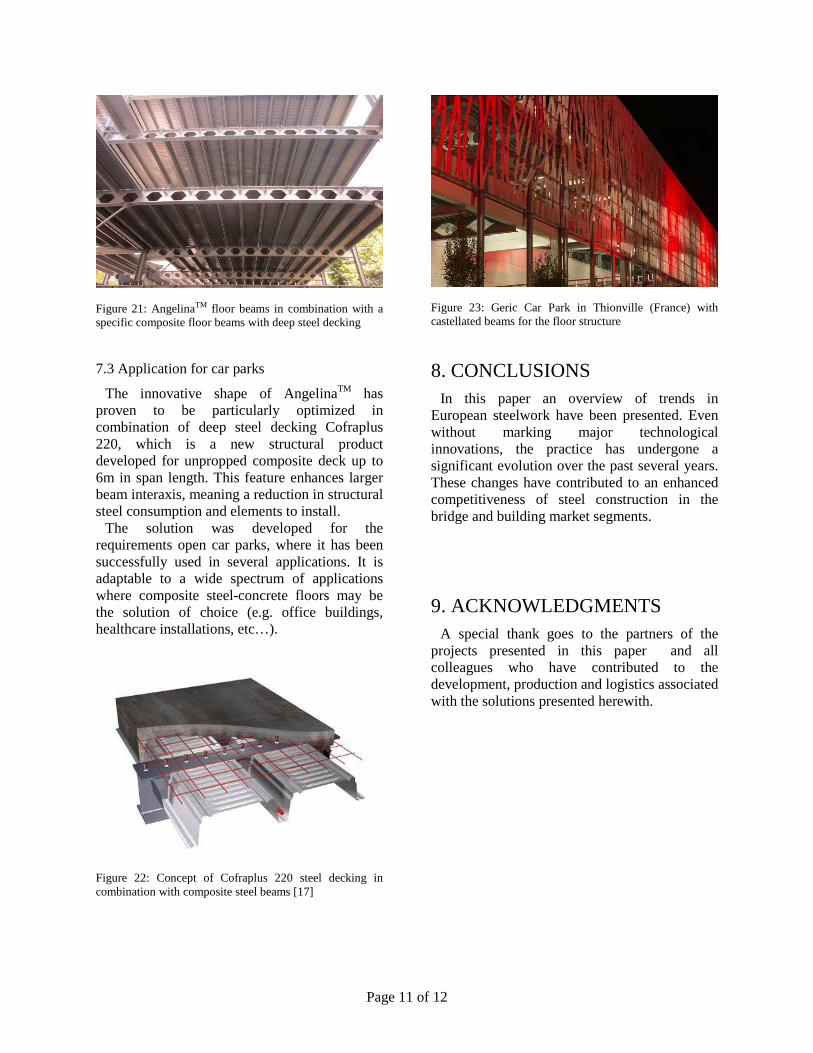
Figure 23: Geric Car Park in Thionville (France) with castellated beams for the floor structure
8. CONCLUSIONS In this paper an overview of trends in
European steelwork have been presented. Even without marking major technological innovations, the practice has undergone a significant evolution over the past several years. These changes have contributed to an enhanced competitiveness of steel construction in the bridge and building market segments.
9. ACKNOWLEDGMENTS A special thank goes to the partners of the
projects presented in this paper and all colleagues who have contributed to the development, production and logistics associated with the solutions presented herewith.

Page 12 of 12
10. LITERATURE [1] D. K. Miller, The Challenge of Welding
Jumbo Shapes, Welding Innovation, Vol. 10, No. 1, 1993.
[2] ProfilArbed, Design of Filler Beam Deck Railway Bridges, UIC, 1999.
[3] Bouchard S., Axmann G., The Steel of Choice, Structural Engineer, 2000.
[4] Hever M., Schröter F., Modern Steel – High Performance Material for High Performance Bridges, 5th International Symposium on Steel Bridges, Barcelona, 2003.
[5] Axmann G., Steel Going Strong, Modern Steel Construction, 2003.
[6] G Sedlacek, B Hoffmeister, H Trumpf - Composite bridge design for small and medium spans - Final Report European commission Technical steel report, EUR20583, 2003.
[7] Weber L., Histar High Performance Hot-Rolled Beams, Advanced Materials for Construction of Bridges, Buildings, and Other Structures III, Engineering Conferences International, 2003.
[8] J. Hoffmann, B. Donnay, Thermo-Mechanical Control processing rolling applications in Sections, Bars and Rails, Profilarbed Recherches, 2004.
[9] O. Hechler, LG. Cajot, PO. Martin, A. Bureau, Efficient and economic design of composite bridges with small and medium spans, ECCS International Symposium of Steel Bridges, 2008.
[10] O. Vassart, LG Cajot, Development of a new composite cellular Beam, The Singapore Engineer, 2008.
[11] Addamiano Engineering, Polo Eccellenza Desio – Case Study, 2010.
[12] J. Müller, Brückenbestand bei der Deutschen Bahn – Bewertung und Ausblick, Preco+ Seminar, Düsseldorf, 24.09.2012.
[13] R. Zanon, W. Ochojski, O. Hechler, Paweł Klimaszewki, W. Lorenc, Road bridges WD7-WD8 on Route Sucharskiego, Gdansk, Poland - Prefabricated composite beams with high-strength hot rolled sections, Technical Report, IABSE
Structural Engineering International (SEI), 2 – 2014.
[14] S. Finnigan, B. Charnish, R. Chmielowski, Steel and the Skyscraper city – A study on the influence of Steel in the design of Tall buildings, CTBUH Conference, New York 2015.
[15] R. Zanon, T. Demarco, M. Sommavilla, New High-Speed railway lines in France – Development of Filler Beam Decks typology, Proceedings of CTA Conference, 2015.
[16] Technical Assistance, ACB and Angelina Beams – A new generation of Castellated Beams, ArcelorMittal Europe – Long Products, Central Marketing, 2015.
[17] COFRAPLUS 220 – for efficient car park design, Arval – ArcelorMittal Europe, 2015.