EMMEDUE BUILDING SYSTEM - M2Dominicana · EMMEDUE BUILDING SYSTEM Operator’s handbook 3....
18
Transcript of EMMEDUE BUILDING SYSTEM - M2Dominicana · EMMEDUE BUILDING SYSTEM Operator’s handbook 3....
EMMEDUE BUILDING SYSTEM Operator’s h
andbook
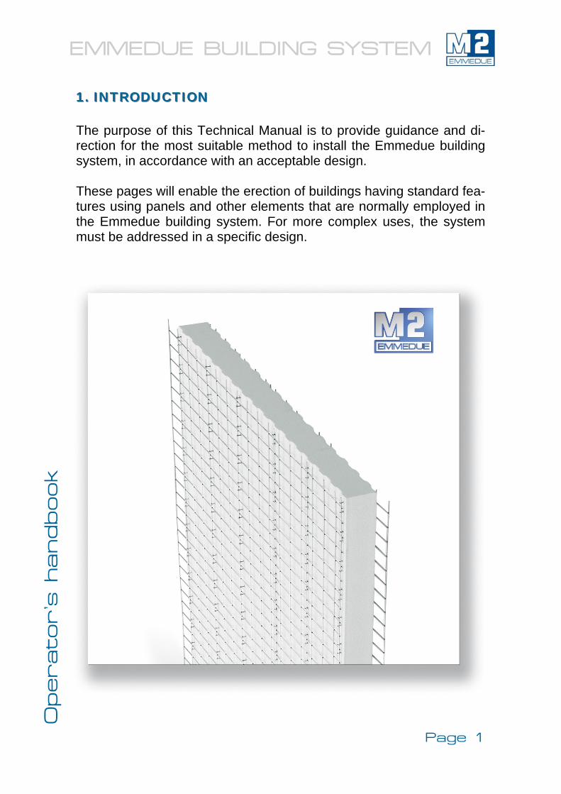
1. INTRODUCTION1. INTRODUCTION The purpose of this Technical Manual is to provide guidance and di-rection for the most suitable method to install the Emmedue building system, in accordance with an acceptable design. These pages will enable the erection of buildings having standard fea-tures using panels and other elements that are normally employed in the Emmedue building system. For more complex uses, the system must be addressed in a specific design.
Page 1
EMMEDUE BUILDING SYSTEM Operator’s h
andbook
2. DESCRIPTION OF THE EMMEDUE BUILDING SYSTEM2. DESCRIPTION OF THE EMMEDUE BUILDING SYSTEM
2.1. FUNDAMENTALS OF THE EMMEDUE SYSTEM2.1. FUNDAMENTALS OF THE EMMEDUE SYSTEM
The Emmedue construction system is based on a series of foam polystyrene panels and galvanized steel wire meshes. The shape has been especially designed for the introduction of traditional or structural plaster (spritz beton) during on-site panel installation. Emmedue provides a system of industrialized modular panelsal-lowing for faster assembly than conventional systems. The Em-medue system fulfils the required structural and load-bearing functions, offering high thermal and sound resistance and a wide range of shapes and finishes to provide versatility in the design compaction process.
2.2. COMPOSITION OF THE EMMEDUE PANELS2.2. COMPOSITION OF THE EMMEDUE PANELS
The following are the basic components: A) A foam polystyrene core which is non-toxic, non-hazardous,
self-extinguishing and chemically inert with varying density and thickness depending on panel type.
B) Electrowelded steel wire meshes made of galvanized drawn steel wires placed on both sides of the polystyrene panel and connected by means of joints of the same material. The wire gauge steel net varies according to panel type and mesh direc-tion.
2.3. PLASTERING2.3. PLASTERING
After the panel assembly, structural plaster should be sprayed and/or poured on the panel - depending on panel type.
Page 2
EMMEDUE BUILDING SYSTEM Operator’s h
andbook
2.4. ADVANTAGES OF THE EMMEDUE BUILDING 2.4. ADVANTAGES OF THE EMMEDUE BUILDING SYSTEM SYSTEM
• Versatility & diversity of panels to accommodate differential architecture and design features
• High heat/cold and sound resistance • Easy to move, rapid assembly with little or no need for lifting
equipment and high durability • Structural capacity and resistance to earthquakes and hurri-
canes • No skilled labour is required • Lower costs and erection time • Lower foundations costs compared with traditional systems • Full utilisation within the same building system • Emmedue system well integrates with traditional systems • Highly fire-proof material • Easy and rapid installation of the plumbing, heating, electric,
telephone systems, etc. • Panels of customised length and thickness • Solid panel connection • Panel surface and Emmedue plastering machines are espe-
cially designed for a smooth plaster spraying • Emmedue panels’ meshes also include connection flanges • The polystyrene core can avoid the thermal bridges • Emmedue panel does not change following exposure to
weather conditions • Ecological in all its parts.
Page 3
EMMEDUE BUILDING SYSTEM Operator’s h
andbook
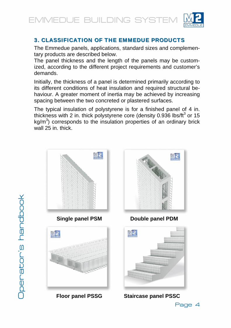
3. CLASSIFICATION OF THE EMMEDUE PRODUCTS3. CLASSIFICATION OF THE EMMEDUE PRODUCTS The Emmedue panels, applications, standard sizes and complemen-tary products are described below. The panel thickness and the length of the panels may be custom-ized, according to the different project requirements and customer’s demands. Initially, the thickness of a panel is determined primarily according to its different conditions of heat insulation and required structural be-haviour. A greater moment of inertia may be achieved by increasing spacing between the two concreted or plastered surfaces. The typical insulation of polystyrene is for a finished panel of 4 in. thickness with 2 in. thick polystyrene core (density 0.936 lbs/ft3 or 15 kg/m3) corresponds to the insulation properties of an ordinary brick wall 25 in. thick.
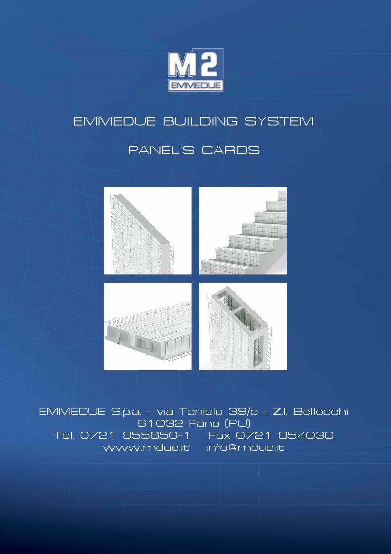
Single panel PSM Double panel PDM
Floor panel PSSG Staircase panel PSSC Page 4
EMMEDUE BUILDING SYSTEM Operator’s h
andbook
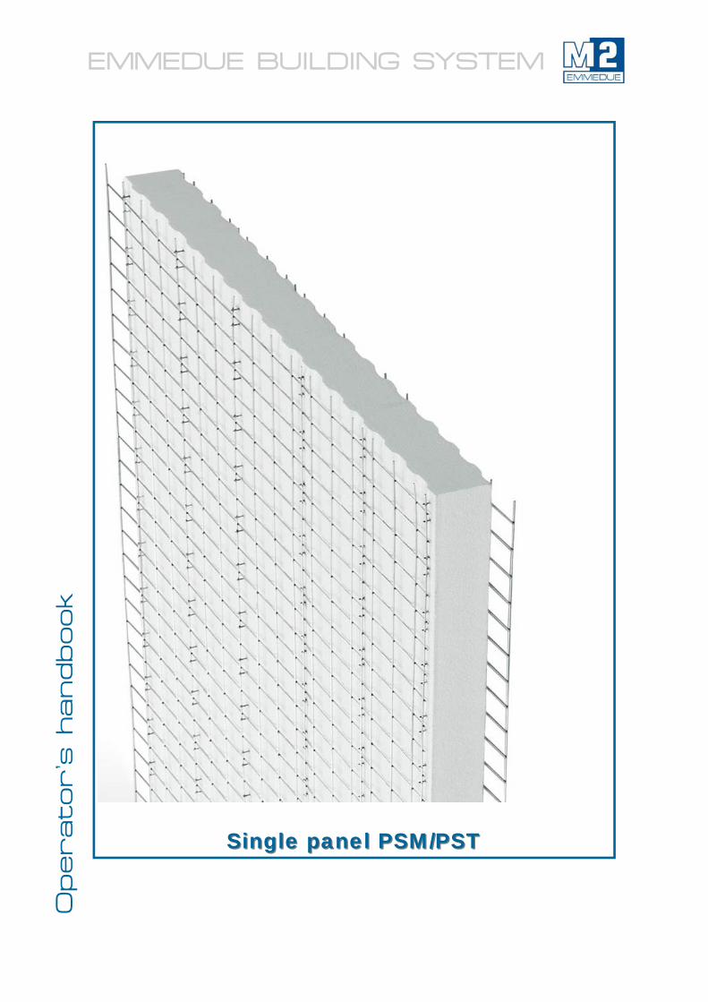
Single panel PSM/PSTSingle panel PSM/PST
EMMEDUE BUILDING SYSTEM Operator’s h
andbook
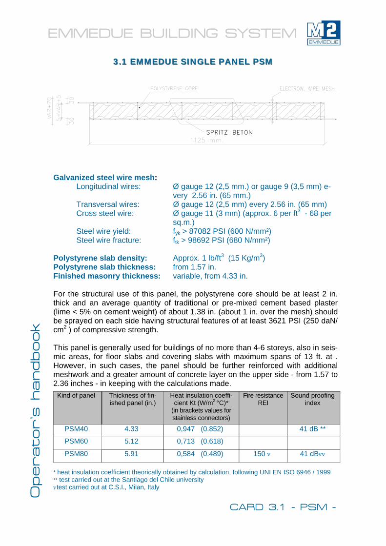
Galvanized steel wire mesh: Longitudinal wires: Ø gauge 12 (2,5 mm.) or gauge 9 (3,5 mm) e-
very 2.56 in. (65 mm.) Transversal wires: Ø gauge 12 (2,5 mm) every 2.56 in. (65 mm) Cross steel wire: Ø gauge 11 (3 mm) (approx. 6 per ft3 - 68 per
sq.m.) Steel wire yield: fyk > 87082 PSI (600 N/mm²) Steel wire fracture: ftk > 98692 PSI (680 N/mm²) Polystyrene slab density: Approx. 1 lb/ft3 (15 Kg/m3) Polystyrene slab thickness: from 1.57 in. Finished masonry thickness: variable, from 4.33 in. For the structural use of this panel, the polystyrene core should be at least 2 in. thick and an average quantity of traditional or pre-mixed cement based plaster (lime < 5% on cement weight) of about 1.38 in. (about 1 in. over the mesh) should be sprayed on each side having structural features of at least 3621 PSI (250 daN/cm2 ) of compressive strength. This panel is generally used for buildings of no more than 4-6 storeys, also in seis-mic areas, for floor slabs and covering slabs with maximum spans of 13 ft. at . However, in such cases, the panel should be further reinforced with additional meshwork and a greater amount of concrete layer on the upper side - from 1.57 to 2.36 inches - in keeping with the calculations made.
* heat insulation coefficient theorically obtained by calculation, following UNI EN ISO 6946 / 1999 ** test carried out at the Santiago del Chile university ∇test carried out at C.S.I., Milan, Italy
Kind of panel Thickness of fin-ished panel (in.)
Heat insulation coeffi-cient Kt (W/m2 °C)*
(in brackets values for stainless connectors)
Fire resistance REI
Sound proofing index
PSM40 4.33 0,947 (0.852) 41 dB **
PSM60 5.12 0,713 (0.618)
PSM80 5.91 0,584 (0.489) 150 ∇ 41 dB∇∇
3.1 EMMEDUE SINGLE PANEL PSM3.1 EMMEDUE SINGLE PANEL PSM
SPRITZ BETON
CARD 3.1 - PSM -
EMMEDUE BUILDING SYSTEM Operator’s h
andbook
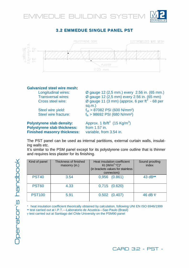
Galvanized steel wire mesh: Longitudinal wires: Ø gauge 12 (2,5 mm.) every 2.56 in. (65 mm.) Transversal wires: Ø gauge 12 (2,5 mm) every 2.56 in. (65 mm) Cross steel wire: Ø gauge 11 (3 mm) (approx. 6 per ft3 - 68 per
sq.m.) Steel wire yield: fyk > 87082 PSI (600 N/mm²) Steel wire fracture: ftk > 98692 PSI (680 N/mm²) Polystyrene slab density: Approx. 1 lb/ft3 (15 Kg/m3) Polystyrene slab thickness: from 1.57 in. Finished masonry thickness: variable, from 3.54 in. The PST panel can be used as internal partitions, external curtain walls, insulat-ing walls etc. It’s similar to the PSM panel except for its polystyrene core outline that is thinner and requires less plaster for its finishing.
* heat insulation coefficient theorically obtained by calculation, following UNI EN ISO 6946/1999 ** test carried out at I.P.T.—Laboratorio de Acustica—Sao Paulo (Brasil) ∇ test carried out at Santiago del Chile University on the PSM90 panel
3.2 EMMEDUE SINGLE PANEL PST3.2 EMMEDUE SINGLE PANEL PST
Kind of panel Thickness of finished masonry (in.)
Heat insulation coefficient Kt (W/m2 °C)*
(in brackets values for stainless connectors)
Sound proofing index
PST40
3.54
0,956 (0.861) 43 dB**
PST60
4.33
0,715 (0.620)
PST100
5.91
0.502 (0.407) 46 dB ∇
CARD 3.2 - PST -
EMMEDUE BUILDING SYSTEM Operator’s h
andbook
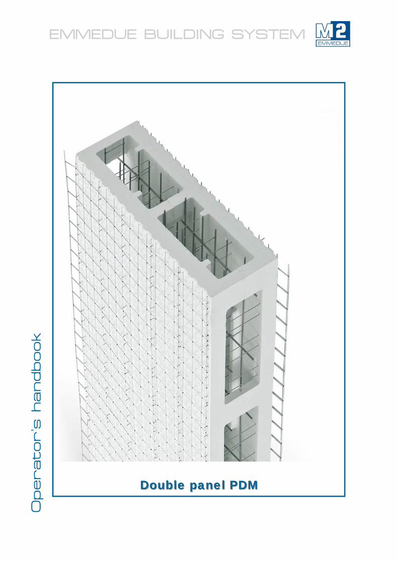
Double panel PDMDouble panel PDM
EMMEDUE BUILDING SYSTEM Operator’s h
andbook
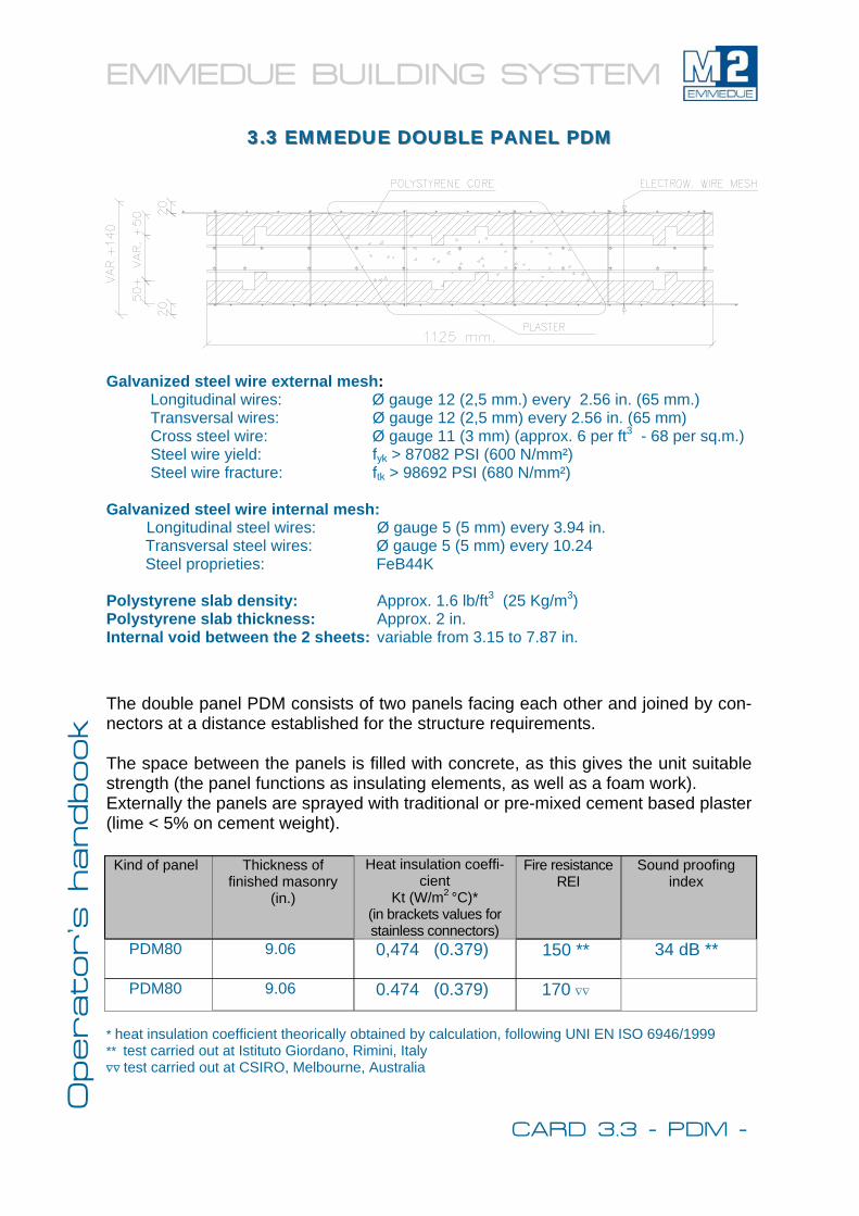
Galvanized steel wire external mesh: Longitudinal wires: Ø gauge 12 (2,5 mm.) every 2.56 in. (65 mm.) Transversal wires: Ø gauge 12 (2,5 mm) every 2.56 in. (65 mm) Cross steel wire: Ø gauge 11 (3 mm) (approx. 6 per ft3 - 68 per sq.m.) Steel wire yield: fyk > 87082 PSI (600 N/mm²) Steel wire fracture: ftk > 98692 PSI (680 N/mm²) Galvanized steel wire internal mesh:
Longitudinal steel wires: Ø gauge 5 (5 mm) every 3.94 in. Transversal steel wires: Ø gauge 5 (5 mm) every 10.24 Steel proprieties: FeB44K
Polystyrene slab density: Approx. 1.6 lb/ft3 (25 Kg/m3) Polystyrene slab thickness: Approx. 2 in. Internal void between the 2 sheets: variable from 3.15 to 7.87 in.
The double panel PDM consists of two panels facing each other and joined by con-nectors at a distance established for the structure requirements. The space between the panels is filled with concrete, as this gives the unit suitable strength (the panel functions as insulating elements, as well as a foam work). Externally the panels are sprayed with traditional or pre-mixed cement based plaster (lime < 5% on cement weight).
* heat insulation coefficient theorically obtained by calculation, following UNI EN ISO 6946/1999 ** test carried out at Istituto Giordano, Rimini, Italy ∇∇ test carried out at CSIRO, Melbourne, Australia
Kind of panel Thickness of finished masonry
(in.)
Heat insulation coeffi-cient
Kt (W/m2 °C)* (in brackets values for stainless connectors)
Fire resistance REI
Sound proofing index
PDM80 9.06 0,474 (0.379) 150 ** 34 dB **
PDM80 9.06 0.474 (0.379) 170 ∇∇
3.3 EMMEDUE DOUBLE PANEL PDM3.3 EMMEDUE DOUBLE PANEL PDM
CARD 3.3 - PDM -
EMMEDUE BUILDING SYSTEM Operator’s h
andbook
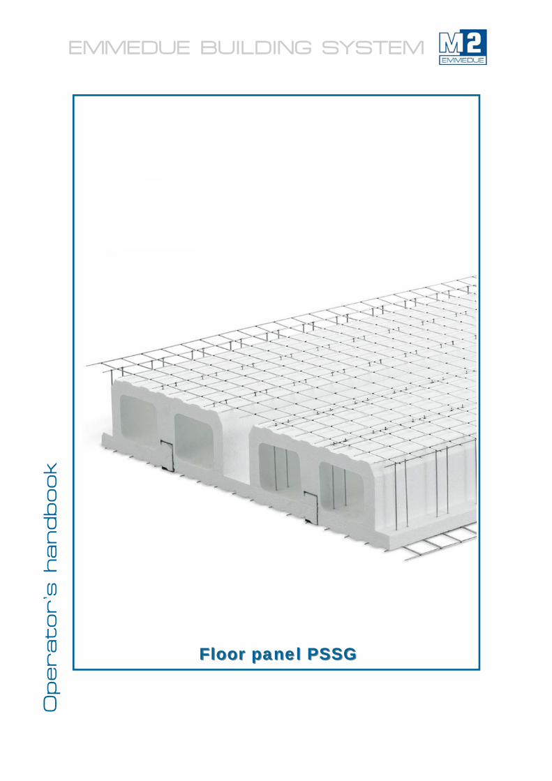
Floor panel PSSGFloor panel PSSG
EMMEDUE BUILDING SYSTEM Operator’s h
andbook
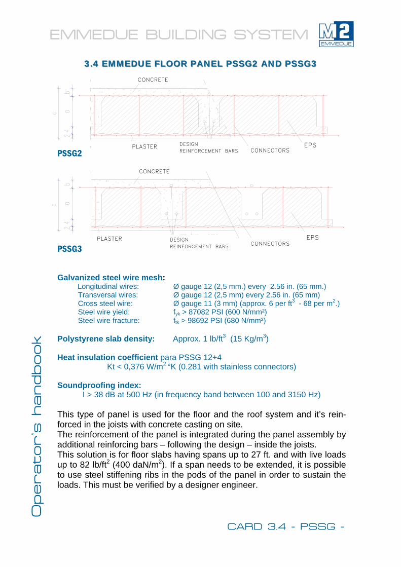
3.4 EMMEDUE FLOOR PANEL PSSG2 AND PSSG33.4 EMMEDUE FLOOR PANEL PSSG2 AND PSSG3
Galvanized steel wire mesh: Longitudinal wires: Ø gauge 12 (2,5 mm.) every 2.56 in. (65 mm.) Transversal wires: Ø gauge 12 (2,5 mm) every 2.56 in. (65 mm) Cross steel wire: Ø gauge 11 (3 mm) (approx. 6 per ft3 - 68 per m2.) Steel wire yield: fyk > 87082 PSI (600 N/mm²) Steel wire fracture: ftk > 98692 PSI (680 N/mm²) Polystyrene slab density: Approx. 1 lb/ft3 (15 Kg/m3) Heat insulation coefficient para PSSG 12+4
Kt < 0,376 W/m2 °K (0.281 with stainless connectors)
Soundproofing index: I > 38 dB at 500 Hz (in frequency band between 100 and 3150 Hz)
This type of panel is used for the floor and the roof system and it’s rein-forced in the joists with concrete casting on site. The reinforcement of the panel is integrated during the panel assembly by additional reinforcing bars – following the design – inside the joists. This solution is for floor slabs having spans up to 27 ft. and with live loads up to 82 lb/ft2 (400 daN/m2). If a span needs to be extended, it is possible to use steel stiffening ribs in the pods of the panel in order to sustain the loads. This must be verified by a designer engineer.
PSSG3
CONCRETE
PLASTER DESIGN REINFORCEMENT BARS CONNECTORS
EPS
CARD 3.4 - PSSG -
PLASTER
CONCRETE
CONNECTORS EPS
PSSG2
DESIGN REINFORCEMENT BARS
EMMEDUE BUILDING SYSTEM Operator’s h
andbook
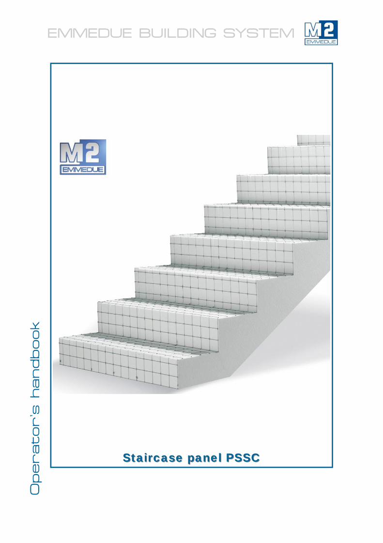
Staircase panel PSSCStaircase panel PSSC
EMMEDUE BUILDING SYSTEM Operator’s h
andbook
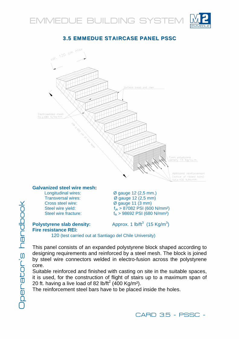
Galvanized steel wire mesh: Longitudinal wires: Ø gauge 12 (2,5 mm.) Transversal wires: Ø gauge 12 (2,5 mm) Cross steel wire: Ø gauge 11 (3 mm) Steel wire yield: fyk > 87082 PSI (600 N/mm²) Steel wire fracture: ftk > 98692 PSI (680 N/mm²) Polystyrene slab density: Approx. 1 lb/ft3 (15 Kg/m3) Fire resistance REI:
120 (test carried out at Santiago del Chile University) This panel consists of an expanded polystyrene block shaped according to designing requirements and reinforced by a steel mesh. The block is joined by steel wire connectors welded in electro-fusion across the polystyrene core. Suitable reinforced and finished with casting on site in the suitable spaces, it is used, for the construction of flight of stairs up to a maximum span of 20 ft. having a live load of 82 lb/ft2 (400 Kg/m²). The reinforcement steel bars have to be placed inside the holes.
3.5 EMMEDUE STAIRCASE PANEL PSSC3.5 EMMEDUE STAIRCASE PANEL PSSC
CARD 3.5 - PSSC -
EMMEDUE BUILDING SYSTEM Operator’s h
andbook
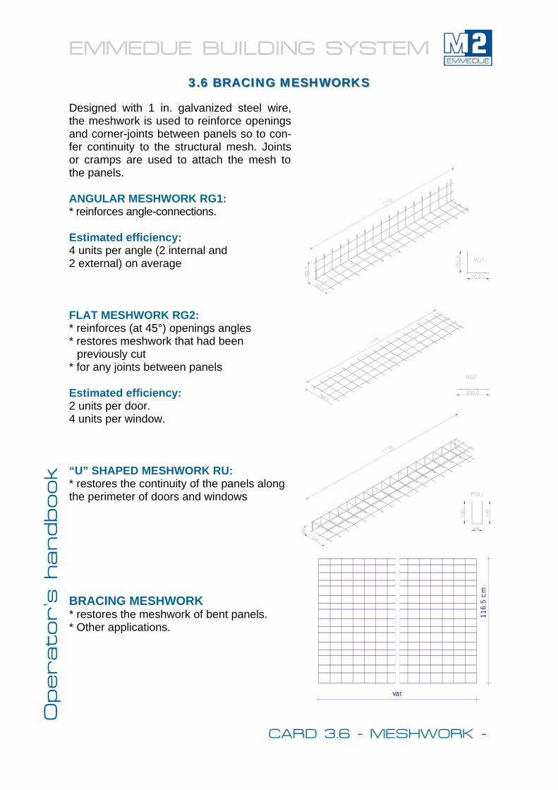
Designed with 1 in. galvanized steel wire, the meshwork is used to reinforce openings and corner-joints between panels so to con-fer continuity to the structural mesh. Joints or cramps are used to attach the mesh to the panels. ANGULAR MESHWORK RG1: * reinforces angle-connections. Estimated efficiency: 4 units per angle (2 internal and 2 external) on average FLAT MESHWORK RG2: * reinforces (at 45°) openings angles * restores meshwork that had been
previously cut * for any joints between panels Estimated efficiency: 2 units per door. 4 units per window. “U” SHAPED MESHWORK RU: * restores the continuity of the panels along the perimeter of doors and windows BRACING MESHWORK * restores the meshwork of bent panels. * Other applications.
116.
5 cm
.
var.
3.6 BRACING MESHWORKS3.6 BRACING MESHWORKS
CARD 3.6 - MESHWORK -
EMMEDUE BUILDING SYSTEM Operator’s h
andbook
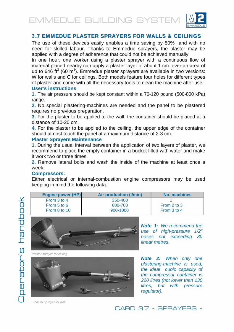
3..77 EM EMMEDUEMEDUE PLASTER SPRAYERS FOR WALLS & PLASTER SPRAYERS FOR WALLS & CEILINGS CEILINGS The use of these devices easily enables a time saving by 50% and with no need for skilled labour. Thanks to Emmedue sprayers, the plaster may be applied with a degree of adherence that could not be achieved manually. In one hour, one worker using a plaster sprayer with a continuous flow of material placed nearby can apply a plaster layer of about 1 cm. over an area of up to 646 ft2 (60 m2). Emmedue plaster sprayers are available in two versions: W for walls and C for ceilings. Both models feature four holes for different types of plaster and come with all the necessary tools to clean the machine after use. User’s instructions 1. The air pressure should be kept constant within a 70-120 pound (500-800 kPa)range. 2. No special plastering-machines are needed and the panel to be plastered requires no previous preparation. 3. For the plaster to be applied to the wall, the container should be placed at a distance of 10-20 cm. 4. For the plaster to be applied to the ceiling, the upper edge of the container should almost touch the panel at a maximum distance of 2-3 cm. Plaster Sprayers Maintenance 1. During the usual interval between the application of two layers of plaster, we recommend to place the empty container in a bucket filled with water and make it work two or three times. 2. Remove lateral bolts and wash the inside of the machine at least once a week. Compressors: Either electrical or internal-combustion engine compressors may be used keeping in mind the following data:
Note 1: We recommend the use of high-pressure 1/2” hoses not exceeding 30 linear metres. Note 2: When only one plastering-machine is used, the ideal cubic capacity of the compressor container is 220 litres (not lower than 130 litres, but with pressure regulator).
Engine power (HP) Air production (l/min) No. machines From 3 to 4 350-400 1 From 5 to 6 600-700 From 2 to 3 From 8 to 10 900-1000 From 3 to 4
Plaster sprayer for wall
Plaster sprayer for ceiling
CARD 3.7 - SPRAYERS -