ELTROTEC Endolight FOT Halogen 150 - Micro-Epsilon · Page 7 Safety ELTROTEC Endolight FOT Halogen...
26
Instruction Manual ELTROTEC Endolight FOT Halogen 150
Transcript of ELTROTEC Endolight FOT Halogen 150 - Micro-Epsilon · Page 7 Safety ELTROTEC Endolight FOT Halogen...
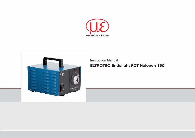
Instruction Manual
ELTROTEC Endolight FOT Halogen 150
Halogen light source
MICRO-EPSILON Eltrotec GmbH Heinkelstraße 2
73066 Uhingen / Germany
Tel. +49 (0) 7161/ 98872-300Fax +49 (0) 7161 / 98872-303 e-mail [email protected]
Certified acc. to DIN EN ISO 9001: 2008

ELTROTEC Endolight FOT Halogen 150
Contents
1. Safety ........................................................................................................................................................ 51.1 Symbols Used ................................................................................................................................................. 51.2 Warnings .......................................................................................................................................................... 51.3 Notes on CE Identification ............................................................................................................................... 61.4 Proper Use ....................................................................................................................................................... 71.5 Proper Environment ......................................................................................................................................... 7
2. Functional Principle, Technical Data ....................................................................................................... 82.1 Short Description ............................................................................................................................................. 82.2 Technical Data ................................................................................................................................................. 8
3. Delivery ..................................................................................................................................................... 93.1 Unpacking ........................................................................................................................................................ 93.2 Storage ............................................................................................................................................................ 9
4. Mounting ................................................................................................................................................. 104.1 Light Source ................................................................................................................................................... 104.2 Control Elements ........................................................................................................................................... 11
5. Operation ................................................................................................................................................ 125.1 Getting Ready for Operation ......................................................................................................................... 125.2 Commissioning .............................................................................................................................................. 125.3 Adjust the Input Voltage 110 / 230 V ............................................................................................................. 145.4 Fuse Replacement ......................................................................................................................................... 155.5 Changing the Lamp ....................................................................................................................................... 16
6. Instructions for Operation ...................................................................................................................... 186.1 General .......................................................................................................................................................... 186.2 Cleaning ......................................................................................................................................................... 18
6.2.1 Housing and Power Supply ......................................................................................................... 186.2.2 Quartz Glass of Light Source ....................................................................................................... 18

ELTROTEC Endolight FOT Halogen 150
7. Warranty ................................................................................................................................................. 19
8. Service, Repair ...................................................................................................................................... 19
9. Decommissioning, Disposal ................................................................................................................. 19
Appendix
A 1 Optional Accessories ............................................................................................................................. 20
A 2 Spare Parts ............................................................................................................................................. 23
A 3 Factory Setting ........................................................................................................................................ 24
Page 5
Safety
ELTROTEC Endolight FOT Halogen 150
1. SafetyThe handling of the system assumes knowledge of the instruction manual.
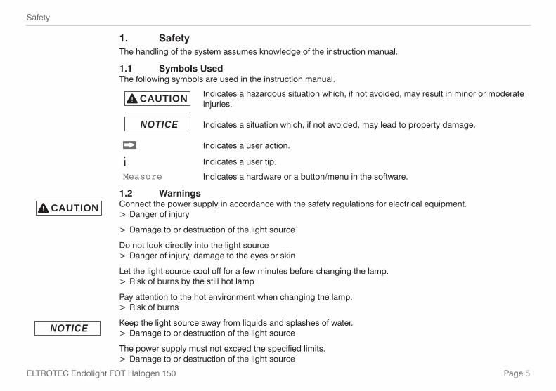
1.1 Symbols UsedThe following symbols are used in the instruction manual.
CAUTION Indicates a hazardous situation which, if not avoided, may result in minor or moderateinjuries.
NOTICE Indicates a situation which, if not avoided, may lead to property damage.
Indicates a user action.
i Indicates a user tip.
Measure Indicates a hardware or a button/menu in the software.
1.2 WarningsConnect the power supply in accordance with the safety regulations for electrical equipment.
> Danger of injury
> Damage to or destruction of the light source
Do not look directly into the light source > Danger of injury, damage to the eyes or skin
Let the light source cool off for a few minutes before changing the lamp. > Risk of burns by the still hot lamp
Pay attention to the hot environment when changing the lamp. > Risk of burns
Keep the light source away from liquids and splashes of water. > Damage to or destruction of the light source
The power supply must not exceed the specified limits. > Damage to or destruction of the light source
CAUTION
NOTICE
Page 6
Safety
ELTROTEC Endolight FOT Halogen 150
The light source may not be operated with opened front panel or removed housing cover. > Damage to or destruction of the light source
Do not insert foreign objects into the openings of the light source. > Damage to or destruction of the light source
1.3 Notes on CE IdentificationThe following applies to the ELTROTEC Endolight FOT Halogen 150 light source:
- EU directive 2004/108/EC - EU directive 2006/95/EC - EU directive 2011/65/EU, “RoHS” category 11
Products which carry the CE mark satisfy the requirements of the quoted EU directives and the European standards (EN) listed therein. The EC declaration of conformity is kept available according to EC regulation, article 10 by the authorities responsible at
MICRO-EPSILON Eltrotec GmbHHeinkelstraße 273066 Uhingen / Germany
The ELTROTEC Endolight FOT Halogen 150 light source is designed for use in industry and satisfies the requirements of the standards
- EN 61000-6-1: 2007 - EN 61000-6-4: 2007
The system satisfies the requirements if they comply with the regulations described in the instruction manualfor installation and operation.
Page 7
Safety
ELTROTEC Endolight FOT Halogen 150
1.4 Proper Use - The ELTROTEC Endolight FOT Halogen 150 light source is designed for use in industrial area with various
fiber optics applications (lighting, endoscopy, etc.). - Light output for up to 13 mm fiber diameter - The ELTROTEC Endolight FOT Halogen 150 light source is not suitable for medical purposes. - The system may only be operated within the limits specified in the technical data, see Chap. 2.2. - Use the ELTROTEC Endolight FOT Halogen 150 light source in such a way that in case of malfunctions or
failure personnel or machinery are not endangered. - Take additional precautions for safety and damage prevention for safety-related applications.
1.5 Proper Environment - Operating temperature: -10 °C to 40 °C 1 (+14 °F to +104 °F 1) - Storage temperature: -25 °C to 60 °C 1 (-13 °F to +140 °F 1) - Humidity: 15 to 95 % - Ambient pressure: Atmospheric pressure - Electromagnetic compatibility (EMC): EN 61000-6-1: 2007
EN 61000-6-4: 20071) Built-in fan for lamp cooling

Page 8
Functional Principle, Technical Data
ELTROTEC Endolight FOT Halogen 150
2. Functional Principle, Technical Data
2.1 Short DescriptionThe ELTROTEC Endolight FOT Halogen 150 light source is regarded as the universal solution when using ex-ternal light sources in the endoscopy. The high light output and simple operation facilitate optimal inspection results. The light intensity is adjusted steplessly with the controllable light sources by means of a mechanical iris diaphragm without the color temperature of the light source is influenced. Different adapters and glass fiber applications permit various uses.
2.2 Technical DataModel ELTROTEC Endolight FOT Halogen 150Power 150 WFiber diameter 13 mm
Operating life typewithout economy mode 100 h
with economy mode ~ 210 h
Weight 5.9 kg
Power supply 110 V 60 Hz / 230 V 50 HzLight source 15 V / 150 WOsram HLX type 64634Color temperature 3400 K
Lamp circuitStep I 100 % intensityStep II 92 % intensity
Lamp cooling Built-in fan
Intensity controlStepless via iris diaphragm
(without affecting the color temperature)Dimensions 240 x 180 x 180 mm (inclusive handle 40 mm)Operating temperature -10 °C to 40 °C (+14 °F to +104 °F)Storage temperature -25 °C to 60 °C (-13 °F to +140 °F)Electromagnetic compatibility (EMC) EN 61000-6-1: 2007 and EN 61000-6-4: 2007

Page 9
Delivery
ELTROTEC Endolight FOT Halogen 150
3. Delivery
3.1 Unpacking - ELTROTEC Endolight FOT Halogen 150 light source - Halogen lamp Osram type HLX 64634 15 V / 150 W - Power supply cable
You will find the suitable fiber optics and fiber-optic lighting units under Optional Accessories, see Chap. A 1
Check the delivery for completeness and shipping damage immediately after unpacking.
In case of damage or missing parts, please contact the manufacturer or supplier immediately.
3.2 Storage - Storage temperature: -25 °C to 60 °C (-13 °F to +140 °F 1) - Humidity: 15 to 95 % - Ambient pressure: Atmospheric pressure

Page 10
Mounting
ELTROTEC Endolight FOT Halogen 150
4. Mounting
4.1 Light Source
40 (
1.57
)14
0 (5
.51)
180 (7.09) 240 (9.45)
Fig. 1 Dimensions ELTROTEC Endolight FOT Halo-gen 150 front view
Fig. 2 Dimensions ELTROTEC Endolight FOT Halogen 150 side view
Dimensions in mm (inches), not to scale
Page 11
Mounting
ELTROTEC Endolight FOT Halogen 150
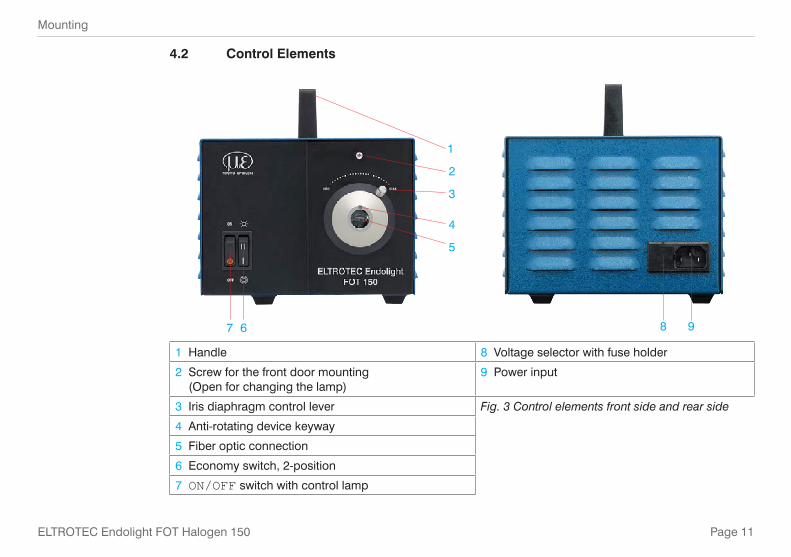
4.2 Control Elements
1
7 6
5
4
3
2
8 9
1 Handle 8 Voltage selector with fuse holder
2 Screw for the front door mounting (Open for changing the lamp)
9 Power input
3 Iris diaphragm control lever Fig. 3 Control elements front side and rear side
4 Anti-rotating device keyway
5 Fiber optic connection
6 Economy switch, 2-position
7 ON/OFF switch with control lamp

Page 12
Operation
ELTROTEC Endolight FOT Halogen 150
5. Operation
5.1 Getting Ready for OperationCheck the built-in heat filter for possible break.
> Damage to the iris diaphragm and the connected fiber optics by excessive heat development
i Set the iris diaphragm control lever (3), see Chap. 4.2, initially at minimum position (left) to prevent glare.
5.2 CommissioningThe light source is supplied as standard for the connection to 230 VAC operating voltage, see Chap. A 3.
Replug the voltage selector (8) for 110 VAC operating voltage by setting the 115 to the positioning ar-row (8), see Chap. 5.3.
i The terminals 120 Volt (positioning arrow (2) is on 125, see Chap. 5.3.) and 240 Volt (position-ing arrow (2) is on 250, see Chap. 5.3.) are not occupied and cannot be used. If the voltage selector has this setting, the light source can therefore not be used.
Connect the supplied power supply cable to the power input (9), see Chap. 4.2 and the power supply.
Connect the fiber optic cable to the fiber optic connection (5), see Chap. 4.2.Some fiber optic cables (e.g. multi-armed gooseneck fiber optic cables) and adapters are fitted with a cam (anti-rotation device), which enters the anti-rotation device keyway (4), see Chap. 4.2, to prevent rotation of the connector.
Press the ON/ OFF switch (7), see Chap. 4.2.
The control lamp lights up. The light source is ready to operate.
Check Always after switching on whether the built-in fan runs (noise). > Destruction of the lamp, the heat protection filter and the iris diaphragm due to excessive heating.
i In case of a defective fan, turn the light source off immediately.
NOTICE
NOTICE

Page 13
Operation
ELTROTEC Endolight FOT Halogen 150
Let the light source cooling down still some minutes after switching off before storing in any closed room or in the original packaging.
> Risk of fire by heat
The lamp power can be adjusted by economy switch (6), see Chap. 4.2. If there is sufficient light the switch should be on level II (intensity 92 %). Thus, a longer lamp lifetime can be achieved.The light intensity can be adjusted steplessly with the iris diaphragm control lever (3), see Chap. 4.2. The light adjustment is made by a mechanical iris diaphragm (without interference of the color temperature).
CAUTION

Page 14
Operation
ELTROTEC Endolight FOT Halogen 150
5.3 Adjust the Input Voltage 110 / 230 V Unplug the power supply cable.
The factory setting of the voltage input is set on 230 VAC operating voltage. The positioning arrow points to 230 (2), see Fig. 4.
To adjust the input voltage to 110 VAC, raise the voltage selector element at the designated cut, see Fig. 4, see Fig. 5, using a screw driver and pull it out.
2 31 4
1 Voltage selector element
2 Positioning arrow
3 Cut to raise the voltage selector element
4 Power supply cable connection
Fig. 4 Detail rear side of light source
Fig. 5 Raise the voltage selector element
Page 15
Operation
ELTROTEC Endolight FOT Halogen 150
Turn the element until the number 115 is on arrow position.
Insert the voltage selector element again and press on it.
Plug in again the power supply cable.
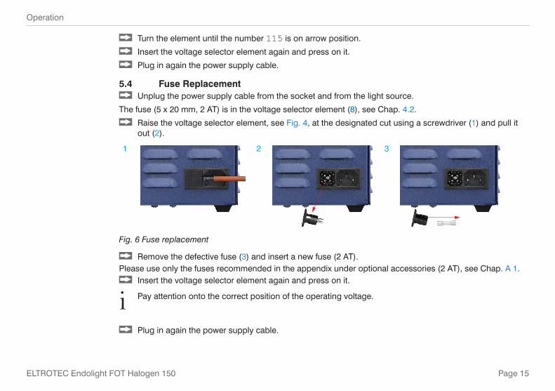
5.4 Fuse Replacement Unplug the power supply cable from the socket and from the light source.
The fuse (5 x 20 mm, 2 AT) is in the voltage selector element (8), see Chap. 4.2.
Raise the voltage selector element, see Fig. 4, at the designated cut using a screwdriver (1) and pull it out (2).
1 2 3
Fig. 6 Fuse replacement
Remove the defective fuse (3) and insert a new fuse (2 AT).Please use only the fuses recommended in the appendix under optional accessories (2 AT), see Chap. A 1.
Insert the voltage selector element again and press on it.
i Pay attention onto the correct position of the operating voltage.
Plug in again the power supply cable.

Page 16
Operation
ELTROTEC Endolight FOT Halogen 150
5.5 Changing the Lamp
Let the light source cool off for a few minutes before changing the lamp. > Risk of burns by the still hot lamp
Do not touch the inside of the lamp (mirror, lamp bulb). > Reducing the intensity and lifetime of the lamp by finger prints and dust
Switch off the ON/OFF switch, see Fig. 3 and disconnect the power supply cable from the wall socket.
Remove the screw, see Fig. 3, on the front side of the light source (1), whereupon the right front door with the lamp unit can be folded down (2).
Loosen the lamp out of the holder carefully (3), lift the spring clip slightly (4) and pull the lamp from the lamp socket (5).
1 Remove the screw
2 Fold down lamp unit
Holder
3 Remove holder
CAUTION
NOTICE

Page 17
ELTROTEC Endolight FOT Halogen 150
4 Lift the spring clip
Holder
5 Lamp socket
Insert the new lamp into the lamp socket and position them into the holder.
i Make sure that the lamp coding is placed again in the designated cut.
Other settings are not required, as the holding system provides an optimum adjustment with a footprint up to 13 mm (maximum applicable fiber diameter).
Close the front door and mount it again with the screw, see Fig. 3.
Plug in the power supply cable.

Page 18
ELTROTEC Endolight FOT Halogen 150
6. Instructions for Operation
6.1 GeneralExcept the descriptive maintenance work (change of lamp, see Chap. 5.5, fuse replacement, see Chap. 5.4, voltage settings, see Chap. 5.3) no repairs or changes at the light source may be made, see Chap. 7., see Chap. 8..
6.2 Cleaning6.2.1 Housing and Power Supply
Turn off the ELTROTEC Endolight FOT Halogen 150 light source and disconnect the power supply cable from the wall socket and from the rear side of the device.
Wipe the exterior surfaces using a damp cloth with mild soapy water.
Wipe the power supply cable using a damp cloth with mild soapy water.
6.2.2 Quartz Glass of Light Source Remove any fingerprints using a cotton swab or isopropyl alcohol (rubbing alcohol).
NOTICEDo not immerse the device in water.Do not connect the device/power supply cable if it is damp. The light source may get damaged or destroyed.

Page 19
ELTROTEC Endolight FOT Halogen 150
7. Warranty All components of the device have been checked and tested for perfect function in the factory. In the unlikely event that errors should occur despite our thorough quality control, this should be reported immediately to MICRO-EPSILON Eltrotec.The warranty period lasts 12 months following the day of shipment. Defective parts, except wear parts, will be repaired or replaced free of charge within this period if you return the device free of cost to MICRO-EPSILON Eltrotec. This warranty does not apply to damage resulting from abuse of the equipment and devices, from forceful handling or installation of the devices or from repair or modifications performed by third parties.No other claims, except as warranted, are accepted. The terms of the purchasing contract apply in full. MICRO-EPSILON Eltrotec will specifically not be responsible for eventual consequential damages. MICRO-EPSILON Eltrotec always strives to supply the customers with the finest and most advanced equipment. Development and refinement is therefore performed continuously and the right to design changes without prior notice is accordingly reserved. For translations in other languages, the data and statements in the Ger-man language operation manual are to be taken as authoritative.
8. Service, Repair
In the event of a defect on the ELTROTEC Endolight FOT Halogen 150 light source or on power supply cable please send us the effected parts for repair or exchange.In the case of faults the cause of which is not clearly identifiable, the whole measuring system must be sent back to:
MICRO-EPSILON Eltrotec GmbH Heinkelstraße 2 73066 Uhingen / Germany Tel. +49 (0) 7161/ 98872-300Fax +49 (0) 7161 / 98872-303 [email protected] www.micro-epsilon.com
9. Decommissioning, Disposal Disconnect the power supply cable from the light source.
The light source is produced according to the directive 2011/65/EU, „RoHS“. Do the disposal according to the legal regulations (see directive 2002/96/EC).
Page 20
Anhang | Optional Accessories
ELTROTEC Endolight FOT Halogen 150
Appendix
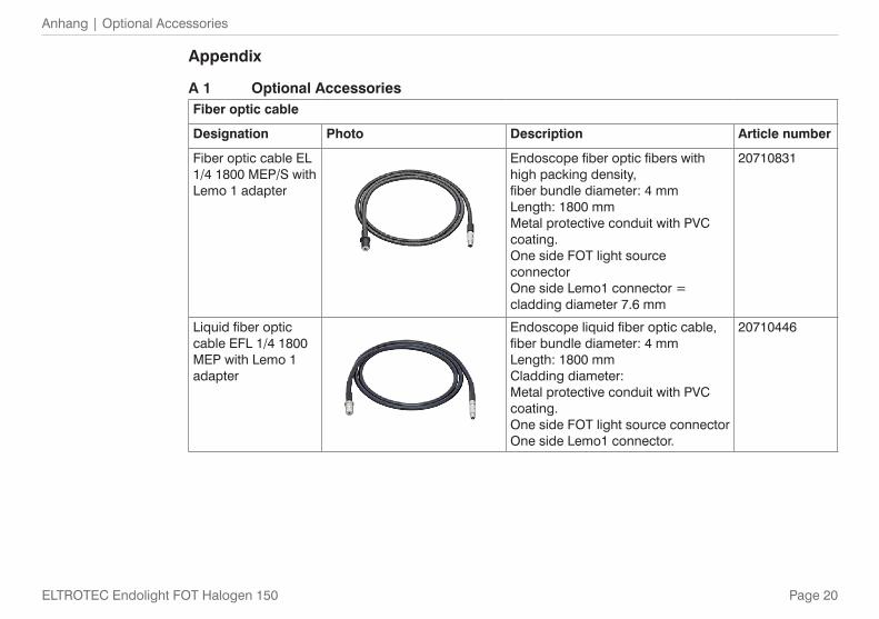
A 1 Optional AccessoriesFiber optic cable
Designation Photo Description Article number
Fiber optic cable EL 1/4 1800 MEP/S with Lemo 1 adapter
Endoscope fiber optic fibers with high packing density,fiber bundle diameter: 4 mmLength: 1800 mm Metal protective conduit with PVC coating. One side FOT light source connector One side Lemo1 connector = cladding diameter 7.6 mm
20710831
Liquid fiber optic cable EFL 1/4 1800 MEP with Lemo 1 adapter
Endoscope liquid fiber optic cable,fiber bundle diameter: 4 mmLength: 1800 mmCladding diameter:Metal protective conduit with PVC coating.One side FOT light source connectorOne side Lemo1 connector.
20710446
Page 21
Anhang | Optional Accessories
ELTROTEC Endolight FOT Halogen 150
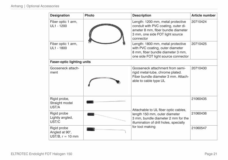
Designation Photo Description Article number
Fiber optic 1 arm, UL1 - 1200
Length: 1200 mm, metal protective conduit with PVC coating, outer di-ameter 8 mm, fiber bundle diameter 3 mm, one side FOT light source connector
20710424
Fiber optic 1 arm, UL1 - 1800
Length: 1800 mm, metal protective with PVC coating, outer diameter 8 mm, fiber bundle diameter 3 mm, one side FOT light source connector
20710425
Faser-optic lighting units
Gooseneck attach-ment
Gooseneck attachment from semi-rigid metal-tube, chrome plated.Fiber bundle diameter 3 mm. Attach-able to cable type UL
20710430
Rigid probe, Straight model UST/A
Attachable to UL fiber optic cables, length 150 mm, outer diameter 3 mm, bundle diameter 2 mm for the illumination of drill holes, specially for tool making
21060435
Rigid probeLightly angled, UST/C
21060436
Rigid probeAngled at 90°, UST/B, r = 10 mm
21060547

Page 22
Anhang | Optional Accessories
ELTROTEC Endolight FOT Halogen 150
Designation Photo Description Article number
Mirror deflectionUS1 mirror on fixture, ø 21 mm
21060432
US2 mirror on fixture, ø 25 mm21060433
USP mirror fixture21060431
Focussing lens
Focussing lens, UFL 21060438;attachable to UL fiber optic
21060438
More fiber optics or faser-optic lighting units are available on request.

Page 23
Anhang | Spare Parts
ELTROTEC Endolight FOT Halogen 150
A 2 Spare Parts
Designation Photo Description Article number
Endolight FOT 150 spare halogen lamp
Osram HLX 64 634 15 V / 150 W
21320385
Designation Article number
Endolight FOT 150 handle 21310974
Endolight FOT 150 Female connector for fiber optics 21311508
Endolight FOT 150 device foot 21310386
Endolight FOT 150 aperture ring 21310388
Endolight FOT 150 mounting ring for heat sink 21310389
Endolight FOT 150 power supply cable 21310402
Endolight FOT 150 fan CN 48 F2 21310401
Endolight FOT 150 transformer no. 30950 21310400
Endolight FOT 150 Mounting connector with voltage selector 42 R 34 21310399
Endolight FOT 150 fuse no. 543 21310398
Endolight FOT 150 power switch 21310397
Endolight FOT 150 lamp socket inclusive flat connector 21310396
Endolight FOT 150 lamp holder with angle and retaining spring 21310395
Endolight FOT 150 heat protection filter 21310394

Page 24
Anhang | Factory Setting
ELTROTEC Endolight FOT Halogen 150
Designation Article number
Endolight FOT 150 holder heat protection filter with spring and bolt 21310393
Endolight FOT 150 aperture holder with mounting ring + iris diaphragm 21310392
Endolight FOT 150 iris diaphragm 21310391
Endolight FOT 150 aperture holder for iris diaphragm 21310390
Power supply cable 1.5 m 21310402
A 3 Factory SettingVoltage input: 230 VAC operating voltage

MICRO-EPSILON Eltrotec GmbH
Heinkelstr. 2 · 73066 Uhingen / Germany
Tel. +49 (0) 7161 / 98872-300 · Fax +49 (0) 7161 / 98872-303
[email protected] · www.micro-epsilon.com
X9751285-A021104HDR
*X9751285-A02*