Electronic Transient Surge Protection ... - TransTech -3P DRI is a “compact design new series”...
40
Transtech Electronic Controls Pty Ltd ABN 21 070 629 499 Perth - Melbourne Perth Tel: (08) 9302-2044 Melbourne Tel: (03) 9330-3624 [email protected] Electronic Transient Surge Protection From Mains Power Supply to Low Volts & Communications Also in Melbourne - Sydney – Brisbane – Adelaide TRANSTECH TRANSTECH ELECTRONIC CONTROLS www.transtech.com.au
-
Upload
truongkhanh -
Category
Documents
-
view
220 -
download
1
Transcript of Electronic Transient Surge Protection ... - TransTech -3P DRI is a “compact design new series”...
Transtech Electronic Controls Pty Ltd ABN 21 070 629 499
Perth - Melbourne Perth Tel: (08) 9302-2044
Melbourne Tel: (03) 9330-3624 [email protected]
Electronic Transient Surge Protection From
Mains Power Supply to Low Volts & Communications
Also in Melbourne - Sydney – Brisbane – Adelaide TRANSTECH
TRA
NST
ECH
ELE
CTR
ON
IC C
ON
TRO
LS
ww
w.tr
anst
ech.
com
.au
Transient Protection Presentation
- 10 – I:\Shared\Price Lists & data sheets\Transtech\Application Notes\TLP Presentation_new.docx TRANSTECH
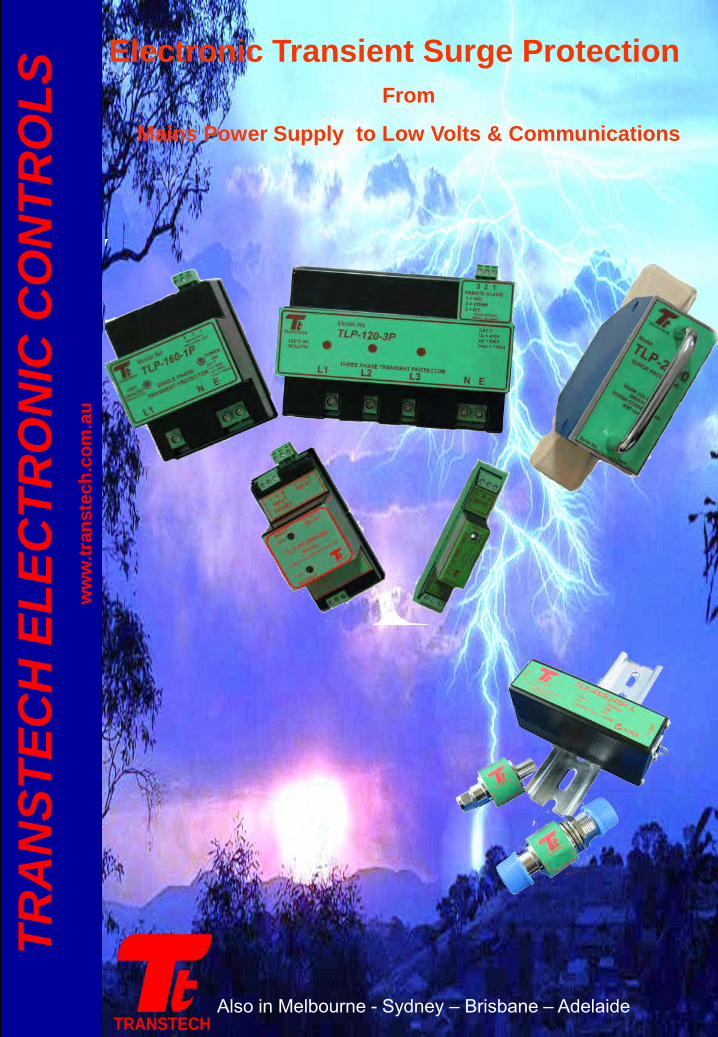
5. Transient Standards Categories and Definitions.
According to AS 1768:2005 the installation of transient over-voltage protectors can be broken down into five (5) categories. Such categories are shown below from highest risk (E) to lowest risk (A): CAT E 6kV / 70kA CAT D 6kV / 30kA CAT C 6kV / 15 - 20kA CAT B 6kV / 3kA CAT A 6kV / 500Amp
The Point of entry to “very exposed or critically important site. Example: Telecom tower on hill.
CAT E – very high risk The point of entry to an exposed rural site. Example: Pump station a Country Area
The point of entry to a site in the City or built up area. Example: Most common building or site
Within a building immediately after the point of entry or Main Board. Example: Sub-boards.
Within a building and fed from a sub-board being CAT B location. Example: GPO,s
C B B
C B A A
1 of 3
FIG 1 FIG 2 FIG 3 FIG 4 FIG 5
AS 1768 IEEE C62 compliant MODELS VOLTAGE Nominal
(Vrms)Maximum (Vrms)
PEAK DISCHARGE CURRENT Per Mode
8/20usec (kA)
MAX “LET-THRU” VOLTAGE
Volts/Modes
INDICATION Visual/Remote FIGURE No
DIMENSIONS in mm
W H D
Main SW/Board -Point of Entry Category C
P =Parallel connection CP=Compact Parallel D=Dual Colour LEDs R=Relay Output I=Remote Indication MB = Modbus Output
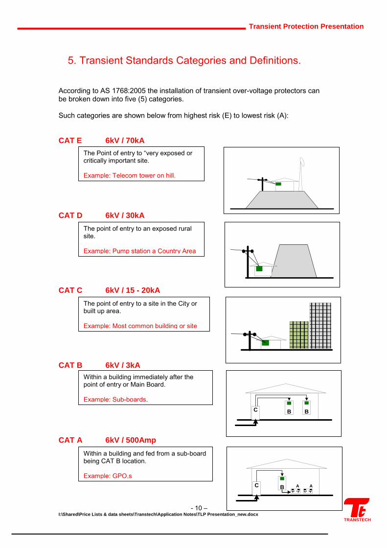
High Spec DIN 1 PH (Cat C) TLP-P40-1P-R 240 / 275 40 <800 / 3 Y / Y FIG 1 80 110 85
DIN PROFILE TLP-P80-1P-R 240 / 275 80 <800 / 3 Y / Y FIG 1 80 110 85
Remote status/Relay Outut TLP-P120-1P-R 240 / 275 120 <800 / 3 Y / Y FIG 1 80 110 85
High Spec /Fault DIN 3PH (Cat C) TLP-CP40-3P-DRI 415 / 475 40 <810 / 3 Y / Y FIG 3 105 120 75
Compact Series DIN PROFILE TLP-CP80-3P-DRI 415 / 475 80 <810 / 3 Y / Y FIG 3 105 120 75
Remote status/Indication capable TLP-CP130-3P-DRI 415 / 475 130 <810 / 3 Y / Y FIG 3 105 120 75
High Spec/Fault DIN 3 PH (Cat C) TLP-P80-3P-DRI 415 / 475 80 <810 / 3 Y / Y FIG 2 150 110 85
DIN PROFILE TLP-P120-3P-DRI 415 / 475 120 <810 / 3 Y / Y FIG 2 150 110 85
Remote status/Indication capable TLP-P160-3P-DRI 415 / 475 160 <810 / 3 Y / Y FIG 2 150 110 85
Modbus Output Available TLP-P200-3P-DRI 415 / 475 200 <810 / 3 Y / Y FIG 2 150 110 85
For Modbus Output add +MB to P/N +MB (modbus output option)
Category B = Sub-Boards
High Spec/Fault DIN 3 PH (Cat B) TLP-150-3P/CAT B (special) 415 / 475 150 <810 / 3 Y / Y FIG 5 150 110 85
Ideal for SubBoard protection
No neutral required for this model TLP-415P-E-DIN (special) 415 / 475 40 <710 / 1 Y FIG 4 45 75 85
Ideal for 3PH Motors & Pumps
CATEGORY C - POINT OF ENTRY TYPES
Process - Industrial - Mining - Commercial - Government - Factories - Research
TLP Transient Lightning Protection
CAT C, ( 20kV and 20 kA) - use eg. TLP-P130-3DRI, TLP-120-3P, TLP-160-3P
DB & Sub Boards CAT B, ( 6kV and 3kA ) - use eg. TLP-150-3P/CATB.
MAINS PROTECTORS Category C = Point of Entry
Note - below list is not the complete range of available product Transtech manufactured
2 of 3
FIG 6 FIG 7 FIG 8 Fig 9 FIG 10
AS 1768, IEEE C62 compliant MODELS VOLTAGE Nominal
(Vrms)/Maximum (Vrms)
PEAK DISCHARGE CURRENT
With 8/20usec (kA)
MAX “LET-THRU” VOLTAGE
Volts/Modes
INDICATION Visual/Remote FIGURE No
DIMENSIONS in mm
W H D
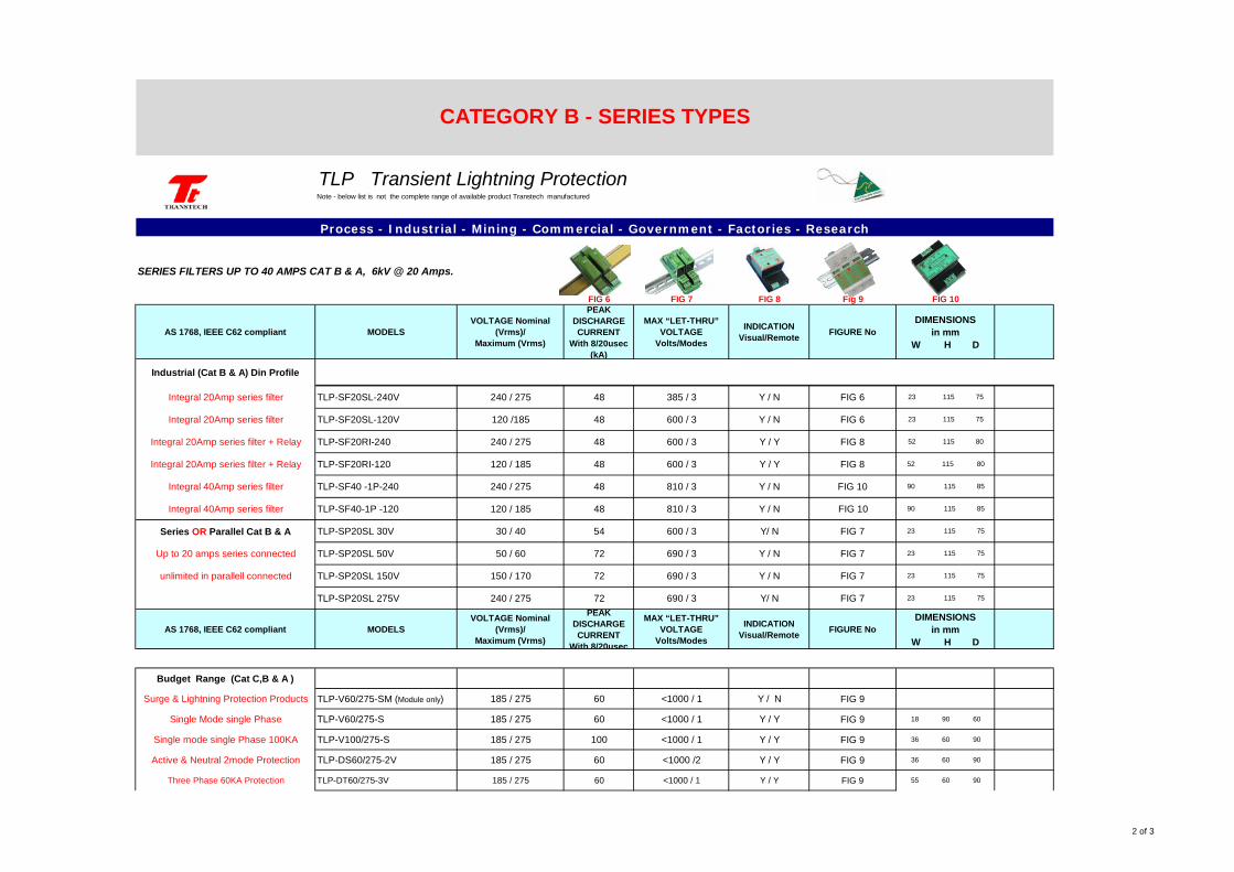
Industrial (Cat B & A) Din Profile
Integral 20Amp series filter TLP-SF20SL-240V 240 / 275 48 385 / 3 Y / N FIG 6 23 115 75
Integral 20Amp series filter TLP-SF20SL-120V 120 /185 48 600 / 3 Y / N FIG 6 23 115 75
Integral 20Amp series filter + Relay TLP-SF20RI-240 240 / 275 48 600 / 3 Y / Y FIG 8 52 115 80
Integral 20Amp series filter + Relay TLP-SF20RI-120 120 / 185 48 600 / 3 Y / Y FIG 8 52 115 80
Integral 40Amp series filter TLP-SF40 -1P-240 240 / 275 48 810 / 3 Y / N FIG 10 90 115 85
Integral 40Amp series filter TLP-SF40-1P -120 120 / 185 48 810 / 3 Y / N FIG 10 90 115 85
Series OR Parallel Cat B & A TLP-SP20SL 30V 30 / 40 54 600 / 3 Y/ N FIG 7 23 115 75
Up to 20 amps series connected TLP-SP20SL 50V 50 / 60 72 690 / 3 Y / N FIG 7 23 115 75
unlimited in parallell connected TLP-SP20SL 150V 150 / 170 72 690 / 3 Y / N FIG 7 23 115 75
TLP-SP20SL 275V 240 / 275 72 690 / 3 Y/ N FIG 7 23 115 75
AS 1768, IEEE C62 compliant MODELS VOLTAGE Nominal
(Vrms)/Maximum (Vrms)
PEAK DISCHARGE CURRENT
With 8/20usec
MAX “LET-THRU” VOLTAGE
Volts/Modes
INDICATION Visual/Remote FIGURE No
DIMENSIONS in mm
W H D
Budget Range (Cat C,B & A )
Surge & Lightning Protection Products TLP-V60/275-SM (Module only) 185 / 275 60 <1000 / 1 Y / N FIG 9
Single Mode single Phase TLP-V60/275-S 185 / 275 60 <1000 / 1 Y / Y FIG 9 18 90 60
Single mode single Phase 100KA TLP-V100/275-S 185 / 275 100 <1000 / 1 Y / Y FIG 9 36 60 90
Active & Neutral 2mode Protection TLP-DS60/275-2V 185 / 275 60 <1000 /2 Y / Y FIG 9 36 60 90
Three Phase 60KA Protection TLP-DT60/275-3V 185 / 275 60 <1000 / 1 Y / Y FIG 9 55 60 90
SERIES FILTERS UP TO 40 AMPS CAT B & A, 6kV @ 20 Amps.
CATEGORY B - SERIES TYPES
Process - Industrial - Mining - Commercial - Government - Factories - Research
TLP Transient Lightning ProtectionNote - below list is not the complete range of available product Transtech manufactured
3 of 3
FIG 11 FIG 12 FIG 13 FIG 14 FIG 15
AS 1768, IEEE C62 compliant MODELS VOLTAGE Nominal
(Vrms)Maximum (Vrms)
PEAK DISCHARGE CURRENT
With 8/20usec (kA)
MAX “LET-THRU” VOLTAGE
Volts/Modes
INDICATION Visual/Remote FIGURE No
DIMENSIONS in mm
W H D
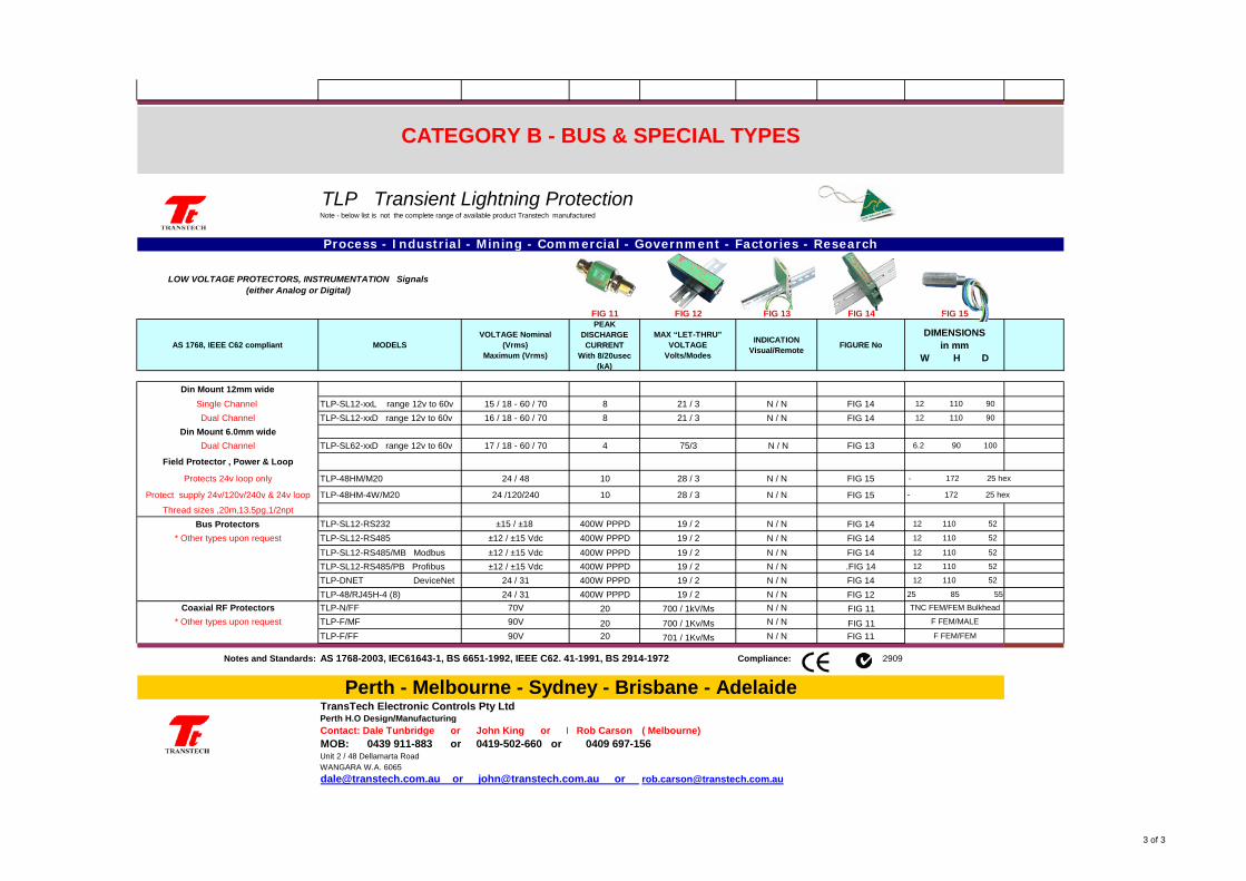
Din Mount 12mm wideSingle Channel TLP-SL12-xxL range 12v to 60v 15 / 18 - 60 / 70 8 21 / 3 N / N FIG 14 12 110 90
Dual Channel TLP-SL12-xxD range 12v to 60v 16 / 18 - 60 / 70 8 21 / 3 N / N FIG 14 12 110 90
Din Mount 6.0mm wide Dual Channel TLP-SL62-xxD range 12v to 60v 17 / 18 - 60 / 70 4 75/3 N / N FIG 13 6.2 90 100
Field Protector , Power & Loop
Protects 24v loop only TLP-48HM/M20 24 / 48 10 28 / 3 N / N FIG 15 - 172 25 hex
Protect supply 24v/120v/240v & 24v loop TLP-48HM-4W/M20 24 /120/240 10 28 / 3 N / N FIG 15 - 172 25 hex
Thread sizes ,20m,13.5pg,1/2nptBus Protectors TLP-SL12-RS232 ±15 / ±18 400W PPPD 19 / 2 N / N FIG 14 12 110 52
* Other types upon request TLP-SL12-RS485 ±12 / ±15 Vdc 400W PPPD 19 / 2 N / N FIG 14 12 110 52
TLP-SL12-RS485/MB Modbus ±12 / ±15 Vdc 400W PPPD 19 / 2 N / N FIG 14 12 110 52
TLP-SL12-RS485/PB Profibus ±12 / ±15 Vdc 400W PPPD 19 / 2 N / N .FIG 14 12 110 52
TLP-DNET DeviceNet 24 / 31 400W PPPD 19 / 2 N / N FIG 14 12 110 52
TLP-48/RJ45H-4 (8) 24 / 31 400W PPPD 19 / 2 N / N FIG 12 25 85 55
Coaxial RF Protectors TLP-N/FF 70V 20 700 / 1kV/Ms N / N FIG 11 TNC FEM/FEM Bulkhead
* Other types upon request TLP-F/MF 90V 20 700 / 1Kv/Ms N / N FIG 11 F FEM/MALE
TLP-F/FF 90V 20 701 / 1Kv/Ms N / N FIG 11 F FEM/FEM
Notes and Standards: AS 1768-2003, IEC61643-1, BS 6651-1992, IEEE C62. 41-1991, BS 2914-1972 Compliance: N2909
TransTech Electronic Controls Pty LtdPerth H.O Design/ManufacturingContact: Dale Tunbridge or John King or M Rob Carson ( Melbourne)MOB: 0439 911-883 or 0419-502-660 or 0409 697-156Unit 2 / 48 Dellamarta RoadWANGARA W.A. [email protected] or [email protected] or [email protected]
CATEGORY B - BUS & SPECIAL TYPES
Perth - Melbourne - Sydney - Brisbane - Adelaide
TLP Transient Lightning ProtectionNote - below list is not the complete range of available product Transtech manufactured
LOW VOLTAGE PROTECTORS, INSTRUMENTATION Signals (either Analog or Digital)
Process - Industrial - Mining - Commercial - Government - Factories - Research
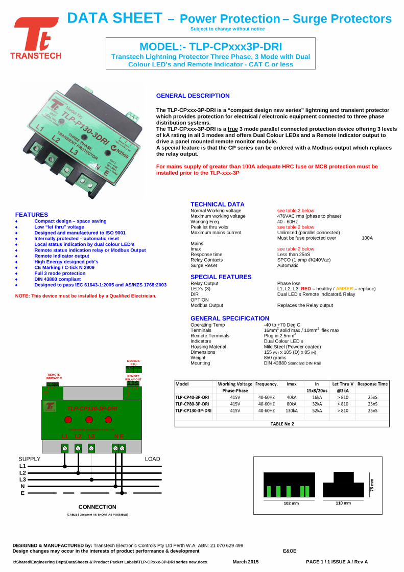
TECHNICAL DATA Normal Working voltage see table 2 below Maximum working voltage 476VAC rms (phase to phase) Working Freq. 40 - 60Hz Peak let thru volts see table 2 below Maximum mains current Unlimited (parallel connected) Must be fuse protected over 100A Mains Imax see table 2 below Response time Less than 25nS Relay Contacts SPCO (1 amp @240Vac) Surge Reset Automatic SPECIAL FEATURES Relay Output Phase loss LED’s (3) L1, L2, L3, RED = healthy / AMBER = replace) DIR Dual LED’s Remote Indicator& Relay OPTION Modbus Output Replaces the Relay output GENERAL SPECIFICATION Operating Temp -40 to +70 Deg C Terminals 16mm2 solid max / 10mm2 flex max Remote Terminals Plug in 2.5mm2 Indicators Dual Colour LED’s Housing Material Mild Steel (Powder coated) Dimensions 155 (W) x 105 (D) x 85 (H) Weight 850 grams Mounting DIN 43880 Standard DIN Rail
MODEL:- TLP-CPxxx3P-DRI Transtech Lightning Protector Three Phase, 3 Mode with Dual
Colour LED’s and Remote Indicator - CAT C or less
DESIGNED & MANUFACTURED by: Transtech Electronic Controls Pty Ltd Perth W.A. ABN: 21 070 629 499 Design changes may occur in the interests of product performance & development E&OE I:\Shared\Engineering Dept\DataSheets & Product Packet Labels\TLP-CPxxx-3P-DRI series new.docx March 2015 PAGE 1 / 1 ISSUE A / Rev A
CONNECTION (CABLES 16sq/mm AS SHORT AS POSSIBLE)
L1L2L3NE
SUPPLY LOAD
TLP-CP130-3P-DRI
THREE PHASE TRANSIENT PROTECTOR
L1 N EL3L2
REMOTE RELAY OUT
Rem
ote
Ala
rm
Rel
ay
3 2 1Remote
Indica tor
3 2 1
MODBUS RTU
REMOTE INDICATOR
DATA SHEET – Power Protection – Surge Protectors Subject to change without notice
GENERAL DESCRIPTION The TLP-CPxxx-3P-DRI is a “compact design new series” lightning and transient protector which provides protection for electrical / electronic equipment connected to three phase distribution systems. The TLP-CPxxx-3P-DRI is a true 3 mode parallel connected protection device offering 3 levels of kA rating in all 3 modes and offers Dual Colour LEDs and a Remote Indicator output to drive a panel mounted remote monitor module. A special feature is that the CP series can be ordered with a Modbus output which replaces the relay output. For mains supply of greater than 100A adequate HRC fuse or MCB protection must be installed prior to the TLP-xxx-3P
102 mm
75 m
m
110 mm
FEATURES ♦ Compact design – space saving ♦ Low “let thru” voltage ♦ Designed and manufactured to ISO 9001 ♦ Internally protected – automatic reset ♦ Local status indication by dual colour LED’s ♦ Remote status indication relay or Modbus Output ♦ Remote Indicator output ♦ High Energy designed pcb’s ♦ CE Marking / C-tick N 2909 ♦ Full 3 mode protection ♦ DIN 43880 compliant ♦ Designed to pass IEC 61643-1:2005 and AS/NZS 1768:2003
NOTE: This device must be installed by a Qualified Electrician.
Model Working Voltage Frequency. Imax In Let Thru V Response TimePhase-Phase 15x8/20us @3kA
TLP-CP40-3P-DRI 415V 40-60HZ 40kA 16kA > 810 25nSTLP-CP80-3P-DRI 415V 40-60HZ 80kA 32kA > 810 25nSTLP-CP130-3P-DRI 415V 40-60HZ 130kA 52kA > 810 25nS
TABLE No 2
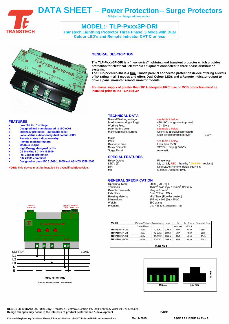
TECHNICAL DATA Normal Working voltage see table 2 below Maximum working voltage 476VAC rms (phase to phase) Working Freq. 40 - 60Hz Peak let thru volts see table 2 below Maximum mains current Unlimited (parallel connected) Must be fuse protected over 100A Mains Imax see table 2 below Response time Less than 25nS Relay Contacts SPCO (1 amp @240Vac) Surge Reset Automatic SPECIAL FEATURES Relay Output Phase loss LED’s (3) L1, L2, L3, RED = healthy / AMBER = replace) DIR Dual LED’s Remote Indicator& Relay MB Modbus Output for BMS GENERAL SPECIFICATION Operating Temp -40 to +70 Deg C Terminals 16mm2 solid max / 10mm2 flex max Remote Terminals Plug in 2.5mm2 Indicators Dual Colour LED’s Housing Material Mild Steel (Powder coated) Dimensions 155 (W) x 105 (D) x 85 (H) Weight 850 grams Mounting DIN 43880 Standard DIN Rail
Model Working Voltage Frequency. Imax In Let Thru V Response TimePhase-Phase 15x8/20us @3kA
TLP-P120-3P-DRI 415V 40-60HZ 120kA 48kA > 810 25nSTLP-P160-3P-DRI 415V 40-60HZ 160kA 64kA > 810 25nSTLP-P200-3P-DRI 415V 40-60HZ 200kA 80kA > 810 25nSTLP-P240-3P-DRI 415V 40-60HZ 240kA 96kA > 810 25nS
TABLE No 2
MODEL:- TLP-Pxxx3P-DRI Transtech Lightning Protector Three Phase, 3 Mode with Dual
Colour LED’s and Remote Indicator CAT C or less
DESIGNED & MANUFACTURED by: Transtech Electronic Controls Pty Ltd Perth W.A. ABN: 21 070 629 499 Design changes may occur in the interests of product performance & development E&OE I:\Shared\Engineering Dept\DataSheets & Product Packet Labels\TLP-Pxxx-3P-DRI series new.docx March 2015 PAGE 1 / 1 ISSUE A / Rev A
CONNECTION (CABLES 16sq/mm AS SHORT AS POSSIBLE)
L1L2L3NE
SUPPLY LOAD
TLP-P120-3P-DRI
THREE PHASE TRANSIENT PROTECTOR
L1 N EL3L2
REMOTE RELAY OUT
MO
DB
US
OU
TPU
T
Rem
ote
Ala
rm
Rel
ay
4 3 2 1 3 2 1Remote
Indica tor
3 2 1
MODBUS RTU
REMOTE INDICATOR
DATA SHEET – Power Protection – Surge Protectors Subject to change without notice
GENERAL DESCRIPTION The TLP-Pxxx-3P-DRI is a “new series” lightning and transient protector which provides protection for electrical / electronic equipment connected to three phase distribution systems. The TLP-Pxxx-3P-DRI is a true 3 mode parallel connected protection device offering 4 levels of kA rating in all 3 modes and offers Dual Colour LEDs and a Remote Indicator output to drive a panel mounted remote monitor module. For mains supply of greater than 100A adequate HRC fuse or MCB protection must be installed prior to the TLP-xxx-3P
155 mm
75 m
m
110 mm
FEATURES ♦ Low “let thru” voltage ♦ Designed and manufactured to ISO 9001 ♦ Internally protected – automatic reset ♦ Local status indication by dual colour LED’s ♦ Remote status indication relay ♦ Remote Indicator output ♦ Modbus Output ♦ High Energy designed pcb’s ♦ CE Marking / C-tick N 2909 ♦ Full 3 mode protection ♦ DIN 43880 compliant ♦ Designed to pass IEC 61643-1:2005 and AS/NZS 1768:2003
NOTE: This device must be installed by a Qualified Electrician.
DESIGNED & MANUFACTURED by: Transtech Electronic Controls Pty Ltd Perth W.A. ABN: 21 070 629 499 Design changes may occur in the interests of product performance & development E&OE PAGE Page 1 of 2 ISSUE A / Rev A I:\Shared\Engineering Dept\DataSheets & Product Packet Labels\TLP-P120-3P+DRI+MBN.docx Confidential Page 1 March 16, 2015
d
DATA SHEET Subject to change without notice
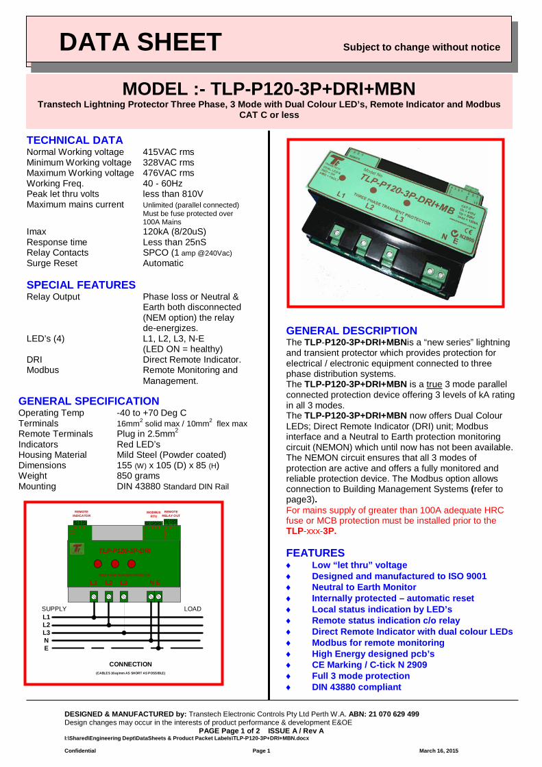
MODEL :- TLP-P120-3P+DRI+MBN Transtech Lightning Protector Three Phase, 3 Mode with Dual Colour LED’s, Remote Indicator and Modbus
CAT C or less
TECHNICAL DATA Normal Working voltage 415VAC rms Minimum Working voltage 328VAC rms Maximum Working voltage 476VAC rms Working Freq. 40 - 60Hz Peak let thru volts less than 810V Maximum mains current Unlimited (parallel connected) Must be fuse protected over 100A Mains Imax 120kA (8/20uS) Response time Less than 25nS Relay Contacts SPCO (1 amp @240Vac) Surge Reset Automatic SPECIAL FEATURES Relay Output Phase loss or Neutral & Earth both disconnected
(NEM option) the relay de-energizes.
LED’s (4) L1, L2, L3, N-E (LED ON = healthy) DRI Direct Remote Indicator. Modbus Remote Monitoring and Management.
GENERAL SPECIFICATION Operating Temp -40 to +70 Deg C Terminals 16mm2 solid max / 10mm2 flex max Remote Terminals Plug in 2.5mm2 Indicators Red LED’s Housing Material Mild Steel (Powder coated) Dimensions 155 (W) x 105 (D) x 85 (H) Weight 850 grams Mounting DIN 43880 Standard DIN Rail
CONNECTION (CABLES 16sq/mm AS SHORT AS POSSIBLE)
L1L2L3NE
SUPPLY LOAD
TLP-P120-3P-DRI
THREE PHASE TRANSIENT PROTECTOR
L1 N EL3L2
REMOTE RELAY OUT
MO
DB
US
OU
TPU
T
Rem
ote
Ala
rm
Rel
ay
4 3 2 1 3 2 1Remote Indica tor
3 2 1
MODBUS RTU
REMOTE INDICATOR
GENERAL DESCRIPTION The TLP-P120-3P+DRI+MBNis a “new series” lightning and transient protector which provides protection for electrical / electronic equipment connected to three phase distribution systems. The TLP-P120-3P+DRI+MBN is a true 3 mode parallel connected protection device offering 3 levels of kA rating in all 3 modes. The TLP-P120-3P+DRI+MBN now offers Dual Colour LEDs; Direct Remote Indicator (DRI) unit; Modbus interface and a Neutral to Earth protection monitoring circuit (NEMON) which until now has not been available. The NEMON circuit ensures that all 3 modes of protection are active and offers a fully monitored and reliable protection device. The Modbus option allows connection to Building Management Systems (refer to page3). For mains supply of greater than 100A adequate HRC fuse or MCB protection must be installed prior to the TLP-xxx-3P. FEATURES ♦ Low “let thru” voltage ♦ Designed and manufactured to ISO 9001 ♦ Neutral to Earth Monitor ♦ Internally protected – automatic reset ♦ Local status indication by LED’s ♦ Remote status indication c/o relay ♦ Direct Remote Indicator with dual colour LEDs ♦ Modbus for remote monitoring ♦ High Energy designed pcb’s ♦ CE Marking / C-tick N 2909 ♦ Full 3 mode protection ♦ DIN 43880 compliant
DATA SHEET Subject to change without notice
DESIGNED & MANUFACTURED by: Transtech Electronic Controls Pty Ltd Perth W.A. ABN: 21 070 629 499 Design changes may occur in the interests of product performance & development E&OE PAGE Page 2 of 2 ISSUE A / Rev A I:\Shared\Engineering Dept\DataSheets & Product Packet Labels\TLP-P120-3P+DRI+MBN.docx Confidential Page 2 March 16, 2015
m
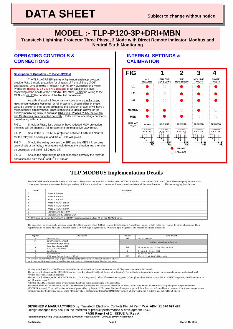
TLP MODBUS Implementation Details The MODBUS interface board can take up to 8 inputs. These inputs are available on the bus using MODBUS function codes 1 (Read Coils) and 2 (Read Discrete Inputs). Both function codes return the same information. Each input reads as ‘0’ if there is a fault or ‘1’ otherwise. Under normal conditions, all inputs will read as ‘1’. The input mapping is as follows:
Input Description 0 Phase A Present 1 Phase B Present 2 Phase C Present 3 Phase A MOV/Fuse OK 4 Phase B MOV/Fuse OK 5 Phase C MOV/Fuse OK 6 Neutral-Earth Fuse OK† 7 Neutral-Earth Resistance OK† † = Only available on units fitted with a NEMON module. Always reads as ‘0’ on non-NEMON units.
The current device setup can be retrieved using MODBUS function codes 3 (Read Holding Register) and 4 (Read Input Register). Both codes will retrieve the same information. These registers can be set using MODBUS function codes 6 (Write Single Register) or 16 (Write Multiple Registers). The register details are as follows:
Register Description Default Valid Values† 0 Device Address 247 1 to 247 inclusive
1‡ Serial Number (Low Word) < value is uniquely set at factory >
2‡ Serial Number (High Word)
3 Baud Rate (divided by 100, e.g. 192 = 19,200 baud) 192 12, 24, 48, 96, 144, 192, 288, 384, 576, 1152
4 Serial Parity 1 0 = None, 1 = Even, 2 = Odd 5 Serial Bus Mode 0 0 = RTU, 1 = ASCII 6 ASCII Mode Timeout (in units of 10ms) 100 50 to 65535 = 0.5 to 65.535 seconds
† = Any value not within the valid range is ignored and the register contents are not modified. No error is returned. ‡ = Register is read-only and cannot be modified. Any writes to these registers are ignored. No error is returned. Writing to registers 3, 4 or 5 will cause the serial communications interface to be restarted and all diagnostics counters to be cleared. The device will also respond to MODBUS function code 43, sub code 14 (Read Device Identification). This will return standard information such as vendor name, product code and revision as per the MODBUS standard The device will also respond to MODBUS function code 8 (Diagnostics). All sub-functions are supported, although the device never returns NAK or BUSY responses, so sub-functions 16 and 17 always return 0. All other MODBUS function codes are unsupported and will cause an error reply to be generated. The default setup will be a device ID of 247 (the maximum ID allowed, and unlikely to already be on a bus), with a baud rate of 19200 and EVEN parity (both as specified by the MODBUS standard). These will be able to be configured either by Transtech Electronic Controls during testing or will be able to be configured by the customer if they have an appropriate computer and RS485 interface to use. Some PLCs may allow configuration from their HMI if they support arbitrary setting of register values in MODBUS slaves.
DATA SHEET Subject to change without notice
OPERATING CONTROLS & CONNECTIONS
L1
L2
L3
NEMON
MEN
RELAY
ALLHEALTHY
N-EMOV BLOWN
MEN LINKFAULTY
N WIREFAULTY
PH LOSSMOV BLOWN
TLP-xxx-3M/NEM
L1 L2 L3 N E
TLP-xxx-3M/NEM
L1 L2 L3 N E
TLP-xxx-3M/NEM
L1 L2 L3 N E
TLP-xxx-3M/NEM
L1 L2 L3 N E
TLP-xxx-3M/NEM
L1 L2 L3 N E
xx xx x
x
xx
DE-ENERGENERGVOLT FREEC/O
DE-ENERG DE-ENERG DE-ENERG
LED = ON
LED = OFF
INTERNAL SETTINGS & CALIBRATION
MODEL :- TLP-P120-3P+DRI+MBN Transtech Lightning Protector Three Phase, 3 Mode with Direct Remote Indicator, Modbus and
Neutral Earth Monitoring
FIG 1 2 3 4 Description of Operation – TLP-xxx-3P/NEM
The TLP-xx-3P/NEM series of lightning/transient protectors provide FULL 3 mode protection for all types of Point of Entry (POE) applications. Unique to the Transtech TLP-xx-3P/NEM series of 3 Mode Protectors (being: L-E / L-N / N-E design), is an additional in-built monitoring of the health of the Earth/Neutral MOV, PLUS the wiring to the MEN link, PLUS the condition of the Neutral connection.
As with all quality 3 Mode transient protectors the Earth and Neutral connection is essential for full protection, should either of these wires be broken or improperly connected the transient protector will have a much reduced effectiveness. TransTech’s unique design allows for the healthy monitoring relay to energise ONLY if all Phases PLUS the Neutral and Earth wires are connected correctly. Under normal operating conditions the following will occur:
FIG 1 Should a Phase lose power or have reduced MOV protection the relay will de-energise (fail-to-safe) and the respective LED go out.
FIG 2 Should the SPD’s MOV protection between Earth and Neutral fail the relay will de-energise and the 4
th LED will go out.
FIG 3 Should the wiring between the SPD and the MEN link become open circuit or be faulty the unique circuit detects the situation and the relay de-energises and the 5
th LED goes off.
FIG 4 Should the Neutral wire be not connected correctly the relay de-energises and both the 4
th and 5
th LED go off.
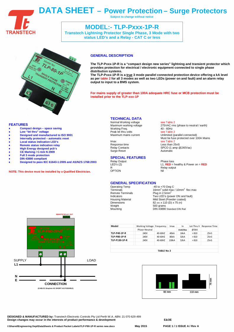
TECHNICAL DATA Normal Working voltage see Table 2 Maximum working voltage 275VAC rms (phase to neutral / earth) Working Freq. 40 - 60Hz Peak let thru volts see Table 2 Maximum mains current Unlimited (parallel connected) Must be fuse protected over 100A Mains Imax see Table 2 Response time Less than 25nS Relay Contacts SPCO (1 amp @240Vac) Surge Reset Automatic SPECIAL FEATURES Relay Output Phase loss LED’s (2) L1, RED = healthy & Power on = RED R Relay output OPTION Nil GENERAL SPECIFICATION Operating Temp -40 to +70 Deg C Terminals 16mm2 solid max / 10mm2 flex max Remote Terminals Plug in 2.5mm2 Indicators Two LED’s (power ON and fault) Housing Material Mild Steel (Powder coated) Dimensions 82 (W) x 110 (D) x 75 (H) Weight 500 grams Mounting DIN 43880 Standard DIN Rail
Model Working Voltage Frequency. Imax In Let Thru V Response TimePhase-Neutral 15x8/20us @3kA
TLP-P40-1P-R 240V 40-60HZ 40kA 16kA > 810 25nSTLP-P80-1P-R 240V 40-60HZ 80kA 32kA > 810 25nSTLP-P130-1P-R 240V 40-60HZ 130kA 52kA > 810 25nS
TABLE No 2
MODEL:- TLP-Pxxx-1P-R Transtech Lightning Protector Single Phase, 3 Mode with two
status LED’s and a Relay - CAT C or less
DESIGNED & MANUFACTURED by: Transtech Electronic Controls Pty Ltd Perth W.A. ABN: 21 070 629 499 Design changes may occur in the interests of product performance & development E&OE I:\Shared\Engineering Dept\DataSheets & Product Packet Labels\TLP-P80-1P-R series new.docx May 2015 PAGE 1 / 1 ISSUE A / Rev A
DATA SHEET – Power Protection – Surge Protectors Subject to change without notice
GENERAL DESCRIPTION The TLP-Pxxx-1P-R is a “compact design new series” lightning and transient protector which provides protection for electrical / electronic equipment connected to single phase distribution systems. The TLP-Pxxx-1P-R is a true 3 mode parallel connected protection device offering a kA level as per table 2 for all 3 modes as well as two LEDs (power on and fault) and an alarm relay output to input to a BMS system. For mains supply of greater than 100A adequate HRC fuse or MCB protection must be installed prior to the TLP-xxx-1P
82 mm
75 m
m
110 mm
FEATURES ♦ Compact design – space saving ♦ Low “let thru” voltage ♦ Designed and manufactured to ISO 9001 ♦ Internally protected – automatic reset ♦ Local status indication LED’s ♦ Remote status indication relay ♦ High Energy designed pcb’s ♦ CE Marking / C-tick N 2909 ♦ Full 3 mode protection ♦ DIN 43880 compliant ♦ Designed to pass IEC 61643-1:2005 and AS/NZS 1768:2003 NOTE: This device must be installed by a Qualified Electrician.
L1
NE
SUPPLY LOAD
CONNECTION (CABLES 16sq/mm AS SHORT AS POSSIBLE)
REMOTE RELAY OUT
TLP-P80-1P-R
SINGLE PHASE TRANSIENT PROTECTOR
L1 N E
3 2 1Remote Alarm
1 = N/O | 2 = COMM | 3 = N/CModel No
TRANSTECH
UNITHEALTHY
(Replace if OFF)
POWERON
CAT CV = 240VIn = 40kA
Imax = 120kA
DATA SHEET Subject to change without notice
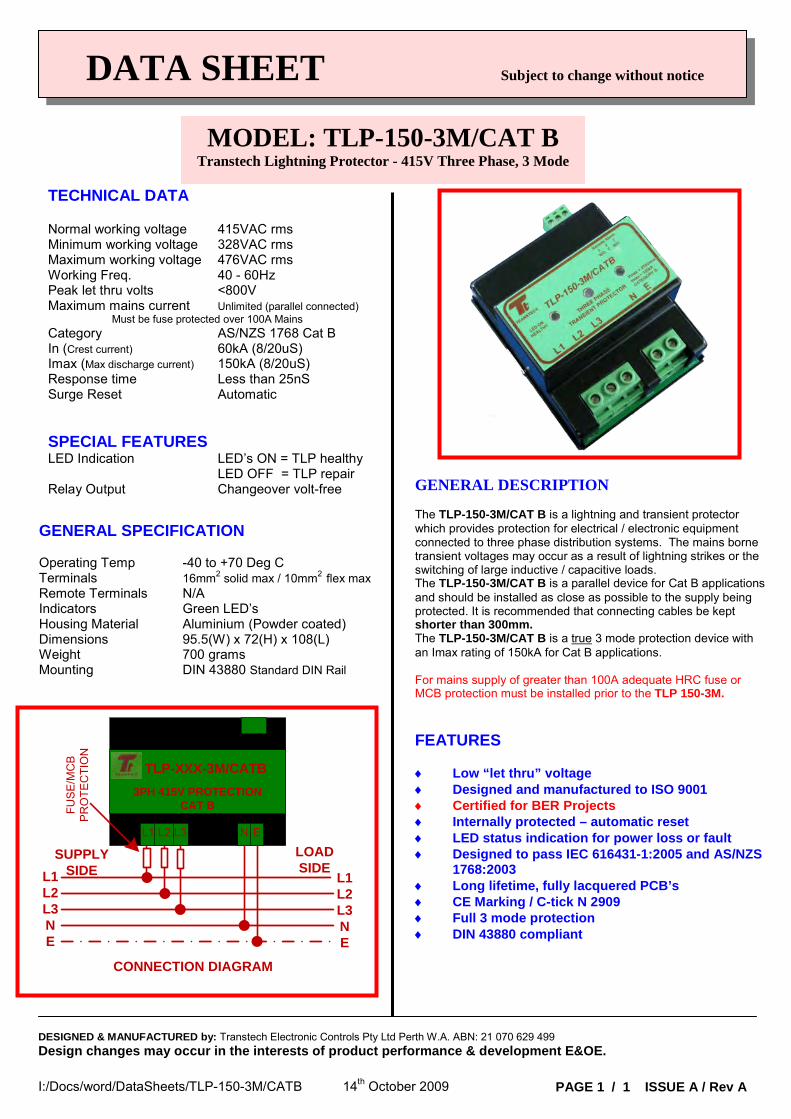
TECHNICAL DATA Normal working voltage 415VAC rms Minimum working voltage 328VAC rms Maximum working voltage 476VAC rms Working Freq. 40 - 60Hz Peak let thru volts <800V Maximum mains current Unlimited (parallel connected)
Must be fuse protected over 100A Mains Category AS/NZS 1768 Cat B In (Crest current) 60kA (8/20uS) Imax (Max discharge current) 150kA (8/20uS) Response time Less than 25nS Surge Reset Automatic SPECIAL FEATURES LED Indication LED’s ON = TLP healthy LED OFF = TLP repair Relay Output Changeover volt-free
GENERAL SPECIFICATION Operating Temp -40 to +70 Deg C Terminals 16mm2 solid max / 10mm2 flex max Remote Terminals N/A Indicators Green LED’s Housing Material Aluminium (Powder coated) Dimensions 95.5(W) x 72(H) x 108(L) Weight 700 grams Mounting DIN 43880 Standard DIN Rail
GENERAL DESCRIPTION The TLP-150-3M/CAT B is a lightning and transient protector which provides protection for electrical / electronic equipment connected to three phase distribution systems. The mains borne transient voltages may occur as a result of lightning strikes or the switching of large inductive / capacitive loads. The TLP-150-3M/CAT B is a parallel device for Cat B applications and should be installed as close as possible to the supply being protected. It is recommended that connecting cables be kept shorter than 300mm. The TLP-150-3M/CAT B is a true 3 mode protection device with an Imax rating of 150kA for Cat B applications. For mains supply of greater than 100A adequate HRC fuse or MCB protection must be installed prior to the TLP 150-3M. FEATURES ♦ Low “let thru” voltage ♦ Designed and manufactured to ISO 9001 ♦ Certified for BER Projects ♦ Internally protected – automatic reset ♦ LED status indication for power loss or fault ♦ Designed to pass IEC 616431-1:2005 and AS/NZS
1768:2003 ♦ Long lifetime, fully lacquered PCB’s ♦ CE Marking / C-tick N 2909 ♦ Full 3 mode protection ♦ DIN 43880 compliant
MODEL: TLP-150-3M/CAT B Transtech Lightning Protector - 415V Three Phase, 3 Mode
I:/Docs/word/DataSheets/TLP-150-3M/CATB 14th October 2009
DESIGNED & MANUFACTURED by: Transtech Electronic Controls Pty Ltd Perth W.A. ABN: 21 070 629 499 Design changes may occur in the interests of product performance & development E&OE.
PAGE 1 / 1 ISSUE A / Rev A
TLP-XXX-3M/CATB
SUPPLY SIDE
LOAD SIDE
L1L2L3NE
L1L2L3NE
CONNECTION DIAGRAM
3PH 415V PROTECTION CAT BFU
SE
/MC
B
PR
OTE
CTI
ON
L1 ENL3L2
DESIGNED & MANUFACTURED in AUSTRALIA by: Transtech Electronic Controls Pty Ltd Perth W.A. ABN: 21 070 629 499 Design changes may occur in the interests of product performance & development E&OE Page 1 of 1 ISSUE A / Rev A I:\Shared\Engineering Dept\DataSheets & Product Packet Labels\TLP-415p e.din new.docx Confidential August 24, 2011
DATA SHEET Subject to change without notice
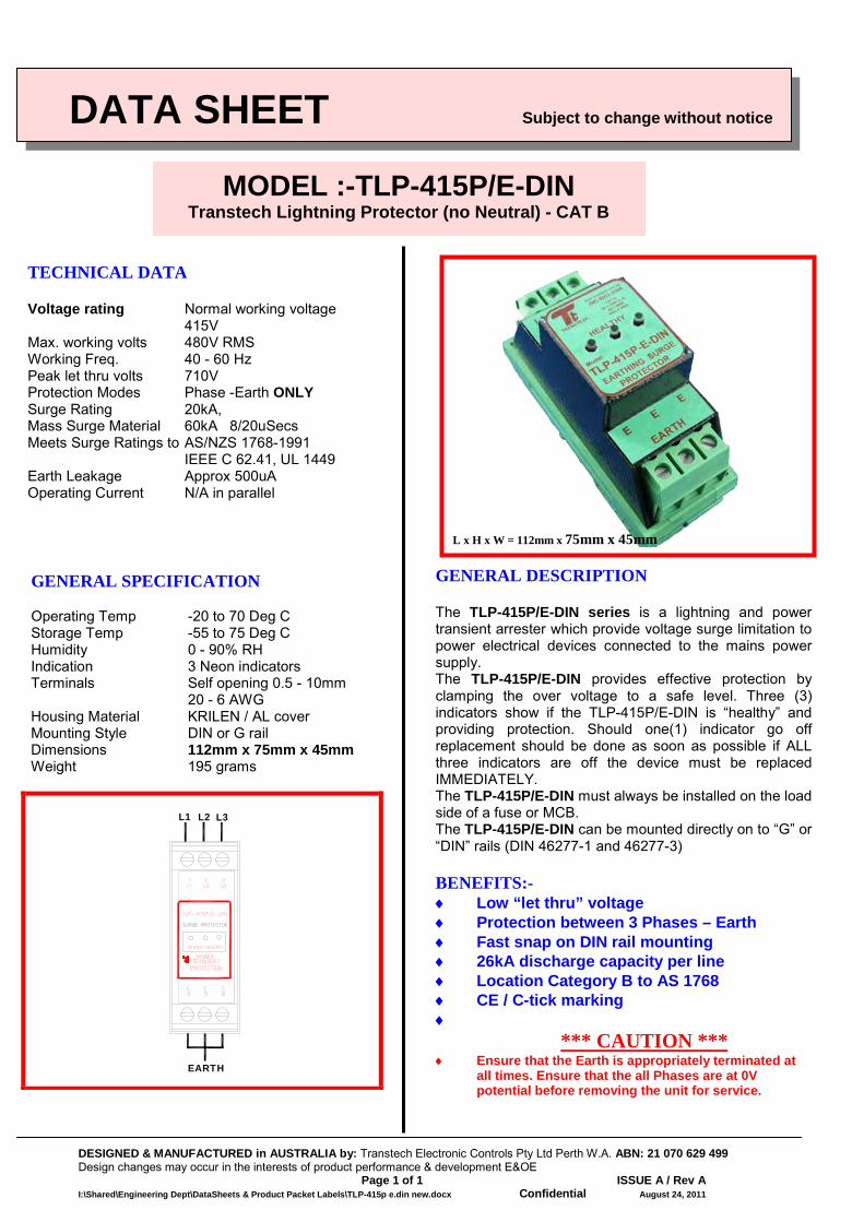
TECHNICAL DATA Voltage rating Normal working voltage
415V Max. working volts 480V RMS Working Freq. 40 - 60 Hz Peak let thru volts 710V Protection Modes Phase -Earth ONLY Surge Rating 20kA, Mass Surge Material 60kA 8/20uSecs Meets Surge Ratings to AS/NZS 1768-1991 IEEE C 62.41, UL 1449 Earth Leakage Approx 500uA Operating Current N/A in parallel
GENERAL SPECIFICATION Operating Temp -20 to 70 Deg C Storage Temp -55 to 75 Deg C Humidity 0 - 90% RH Indication 3 Neon indicators Terminals Self opening 0.5 - 10mm 20 - 6 AWG Housing Material KRILEN / AL cover Mounting Style DIN or G rail Dimensions 112mm x 75mm x 45mm Weight 195 grams
L1 L2 L3
EARTH
GENERAL DESCRIPTION The TLP-415P/E-DIN series is a lightning and power transient arrester which provide voltage surge limitation to power electrical devices connected to the mains power supply. The TLP-415P/E-DIN provides effective protection by clamping the over voltage to a safe level. Three (3) indicators show if the TLP-415P/E-DIN is “healthy” and providing protection. Should one(1) indicator go off replacement should be done as soon as possible if ALL three indicators are off the device must be replaced IMMEDIATELY. The TLP-415P/E-DIN must always be installed on the load side of a fuse or MCB. The TLP-415P/E-DIN can be mounted directly on to “G” or “DIN” rails (DIN 46277-1 and 46277-3) BENEFITS:- ♦ Low “let thru” voltage ♦ Protection between 3 Phases – Earth ♦ Fast snap on DIN rail mounting ♦ 26kA discharge capacity per line ♦ Location Category B to AS 1768 ♦ CE / C-tick marking ♦
*** CAUTION *** ♦ Ensure that the Earth is appropriately terminated at
all times. Ensure that the all Phases are at 0V potential before removing the unit for service.
MODEL :-TLP-415P/E-DIN Transtech Lightning Protector (no Neutral) - CAT B
L x H x W = 112mm x 75mm x 45mm
DATA SHEET Subject to change without notice
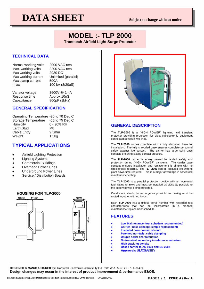
TECHNICAL DATA Normal working volts 2000 VAC rms Max. working volts 2200 VAC rms Max working volts 2930 DC Max working current Unlimited (parallel) Max clamp current 500A Imax 100 kA (8/20uS) Varistor voltage 3600V @ 1mA Response time Approx 10nS Capacitance 800pF (1kHz) GENERAL SPECIFICATION Operating Temperature -20 to 70 Deg C Storage Temperature -55 to 75 Deg C Humidity 0 - 90% RH Earth Stud M8 Cable Entry 9.5mm Weight 1.5kg TYPICAL APPLICATIONS ♦ Airfield Lighting Protection ♦ Lighting Systems ♦ Commercial Buildings ♦ Overhead Power Lines ♦ Underground Power Lines ♦ Service / Distribution Boards
GENERAL DESCRIPTION The TLP-2000 is a “HIGH POWER” lightning and transient protector providing protection for electrical/electronic equipment connected between two lines. The TLP-2000 comes complete with a fully shrouded base for installation. The fully shrouded base ensures complete personnel safety against live contact. The carrier has large solid bass contacts ensuring lasting contact pressure. The TLP-2000 carrier is epoxy sealed for added safety and protection during “HIGH POWER” transients. The carrier base concept ensures installation and replacement is simple with no special tools required. The TLP-2000 can be replaced live with no plant down time required. This is a major advantage in scheduled maintenance/testing. The TLP-2000 is a parallel protection device with an increased fault rating to 80kA and must be installed as close as possible to the supply/device being protected. Conductors should be as large as possible and wiring must be routed together with no loops. Each TLP-2000 has a unique serial number with recorded test characteristics that can be incorporated in a planned maintenance/replacement schedule. FEATURES ♦ Low Maintenance (test schedule recommended) ♦ Carrier / base concept (simple replacement) ♦ Insulated base contact shroud ♦ Patented non-twist cable clamping ♦ Unique serial characteristics ♦ No transient secondary interference emission ♦ High stacking density ♦ Base / carrier to AS 1033 and BS 2692 ♦ Approvals UL/CSA/SEV
MODEL :- TLP 2000 Transtech Airfield Light Surge Protector
I:\Shared\Engineering Dept\DataSheets & Product Packet Labels\TLP-2000 new.doc 30 April 2015
DESIGNED & MANUFACTURED by: Transtech Electronic Controls Pty Ltd Perth W.A. ABN: 21 070 629 499 Design changes may occur in the interest of product improvement & performance E&OE. PAGE 1 / 1 ISSUE A / Rev A
DESIGNED & MANUFACTURED by: Transtech Electronic Controls Pty Ltd Perth W.A. ABN: 21 070 629 499 Design changes may occur in the interests of product performance & development E&OE PAGE Page 1 of 1 ISSUE A / Rev A I:\Shared\Engineering Dept\DataSheets & Product Packet Labels\TLP-DSI.doc Confidential Page 1 March 12, 2013
d
DATA SHEET Subject to change without notice
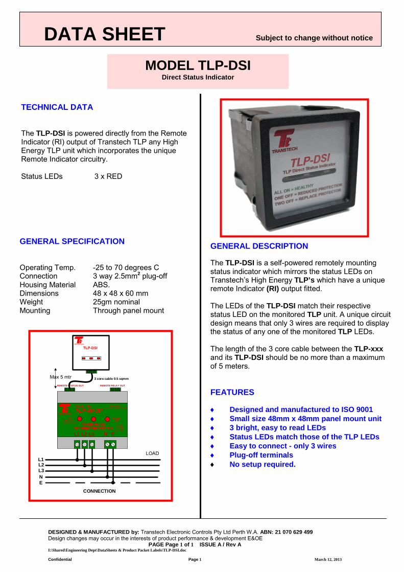
TECHNICAL DATA The TLP-DSI is powered directly from the Remote Indicator (RI) output of Transtech TLP any High Energy TLP unit which incorporates the unique Remote Indicator circuitry. Status LEDs 3 x RED
GENERAL SPECIFICATION Operating Temp. -25 to 70 degrees C Connection 3 way 2.5mm2 plug-off Housing Material ABS. Dimensions 48 x 48 x 60 mm Weight 25gm nominal Mounting Through panel mount
GENERAL DESCRIPTION The TLP-DSI is a self-powered remotely mounting status indicator which mirrors the status LEDs on Transtech’s High Energy TLP’s which have a unique remote Indicator (RI) output fitted. The LEDs of the TLP-DSI match their respective status LED on the monitored TLP unit. A unique circuit design means that only 3 wires are required to display the status of any one of the monitored TLP LEDs. The length of the 3 core cable between the TLP-xxx and its TLP-DSI should be no more than a maximum of 5 meters. FEATURES ♦ Designed and manufactured to ISO 9001 ♦ Small size 48mm x 48mm panel mount unit ♦ 3 bright, easy to read LEDs ♦ Status LEDs match those of the TLP LEDs ♦ Easy to connect - only 3 wires ♦ Plug-off terminals ♦ No setup required.
MODEL TLP-DSI Direct Status Indicator
L1
NE
LOAD
CONNECTION
REMOTE RELAY OUT
TLP-40-3P
THREE PHASE TRANSIENT PROTECTOR
N E
3 2 1Remote Alarm
1 = N/O | 2 = COMM | 3 = N/CModel No
TRANSTECH
UNITHEALTHY
(Replace if OFF)
POWERON
CAT CV = 240VIn = 40kA
Imax = 120kA
REMOTE STATUS OUT
3 core cable 0.5 sqmmMax 5 mtr
TLP-DSITRANST ECH
L1 L2 L3
L2L3
DESIGNED & MANUFACTURED by: Transtech Electronic Controls Pty Ltd Perth W.A. ABN: 21 070 629 499 Design changes may occur in the interests of product performance & development E&OE PAGE Page 1 of 1 ISSUE A / Rev A I:\Shared\Engineering Dept\DataSheets & Product Packet Labels\TLP-PSI.docx Confidential Page 1 March 7, 2013
d
DATA SHEET Subject to change without notice
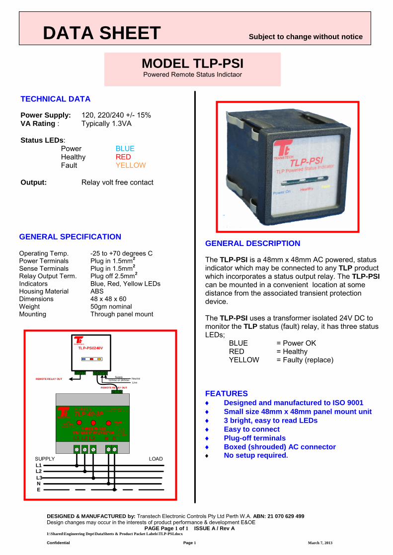
TECHNICAL DATA Power Supply: 120, 220/240 +/- 15% VA Rating : Typically 1.3VA Status LEDs: Power BLUE Healthy RED Fault YELLOW Output: Relay volt free contact
GENERAL SPECIFICATION Operating Temp. -25 to +70 degrees C Power Terminals Plug in 1.5mm2
Sense Terminals Plug in 1.5mm2
Relay Output Term. Plug off 2.5mm2 Indicators Blue, Red, Yellow LEDs Housing Material ABS Dimensions 48 x 48 x 60 Weight 50gm nominal Mounting Through panel mount
GENERAL DESCRIPTION The TLP-PSI is a 48mm x 48mm AC powered, status indicator which may be connected to any TLP product which incorporates a status output relay. The TLP-PSI can be mounted in a convenient location at some distance from the associated transient protection device. The TLP-PSI uses a transformer isolated 24V DC to monitor the TLP status (fault) relay, it has three status LEDs;
BLUE = Power OK RED = Healthy YELLOW = Faulty (replace)
FEATURES ♦ Designed and manufactured to ISO 9001 ♦ Small size 48mm x 48mm panel mount unit ♦ 3 bright, easy to read LEDs ♦ Easy to connect ♦ Plug-off terminals ♦ Boxed (shrouded) AC connector ♦ No setup required.
MODEL TLP-PSI Powered Remote Status Indictaor
L1
NE
SUPPLY LOAD
REMOTE RELAY OUT
TLP-40-3P
THREE PHASE TRANSIENT PROTECTOR
N E
3 2 1Remote Alarm
1 = N/O | 2 = COMM | 3 = N/CModel No
TRANSTECH
UNITHEALTHY
(Replace if OFF)
POWERON
CAT CV = 240VIn = 40kA
Imax = 120kA
TLP-PSI/240VTRANST ECH
REMOTE RELAY OUT NeutralLine
Supply120Vac or 240Vac
L1 L2 L3
L2L3
DATA SHEET Subject to change without notice
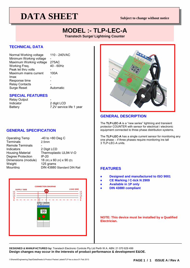
TECHNICAL DATA Normal Working voltage 110 - 240VAC Minimum Working voltage - Maximum Working voltage 275AC Working Freq. 40 - 60Hz Peak let thru volts - Maximum mains current 100A Imax - Response time - Relay Contacts - Surge Reset Automatic SPECIAL FEATURES Relay Output - Indicator 2 digit LCD Battery 7.2V service life 1 year
GENERAL SPECIFICATION Operating Temp -40 to +80 Deg C Terminals 2.5mm Remote Terminals - Indicators 2 Digit LCD Housing Material Thermoplastic UL94-V-O Degree Protection IP-20 Dimensions (module) 18 (W) x 60 (H) x 90 (D) Weight 125 grams Mounting DIN 43880 Standard DIN Rail
GENERAL DESCRIPTION The TLP-LEC-A is a “new series” lightning and transient protector COUNTER with sensor for electrical / electronic equipment connected to three phase distribution systems. The TLP-LEC-A has a single current sensor for monitoring any one phase – if three phases require monitoring ins tall 3 TLP-LEC-A units. FEATURES ♦ Designed and manufactured to ISO 9001 ♦ CE Marking / C-tick N 2909 ♦ Available in 1P only ♦ DIN 43880 compliant NOTE: This device must be installed by a Qualified Electrician.
MODEL :- TLP-LEC-A Transtech Surge/ Lightning Counter
I:\Shared\Engineering Dept\DataSheets & Product Packet Labels\TLP-lec-a.docx 01 Feb 2013
DESIGNED & MANUFACTURED by: Transtech Electronic Controls Pty Ltd Perth W.A. ABN: 21 070 629 499 Design changes may occur in the interests of product performance & development E&OE.
PAGE 1 / 1 ISSUE A / Rev A
CONNECTION DIAGRAM
SUPPLY SIDE LOAD SIDEL1L2L3
L1L2L3NE
NE
TRANSTECH
SUPPLYL N
SENSOR
TLP-LEC-A
99
Transtech Electronic Controls Pty Ltd ABN 21 070 629 499
Perth - Melbourne Perth Tel: (08) 9302-2044
Melbourne Tel: (03) 9330-3624 [email protected]
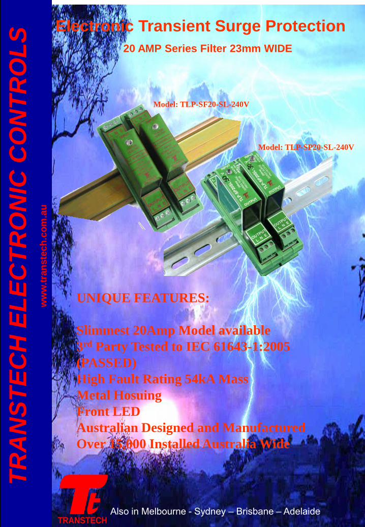
Electronic Transient Surge Protection 20 AMP Series Filter 23mm WIDE
Also in Melbourne - Sydney – Brisbane – Adelaide TRANSTECH
TRA
NST
ECH
ELE
CTR
ON
IC C
ON
TRO
LS
ww
w.tr
anst
ech.
com
.au
UNIQUE FEATURES: Slimmest 20Amp Model available 3rd Party Tested to IEC 61643-1:2005 (PASSED) High Fault Rating 54kA Mass Metal Hosuing Front LED Australian Designed and Manufactured Over 15,000 Installed Australia Wide
Model: TLP-SF20-SL-240V
Model: TLP-SP20-SL-240V
DESIGNED & MANUFACTURED by: Transtech Electronic Controls Pty Ltd Perth W.A. ABN: 21 070 629 499 Design changes may occur in the interests of product performance & development E&OE PAGE Page 1 of 2 ISSUE A / Rev C I:\Shared\Engineering Dept\DataSheets & Product Packet Labels\TLP-SF20SL-240V revc.docx Confidential Page 1 November 2, 2011
d
DATA SHEET Subject to change without notice
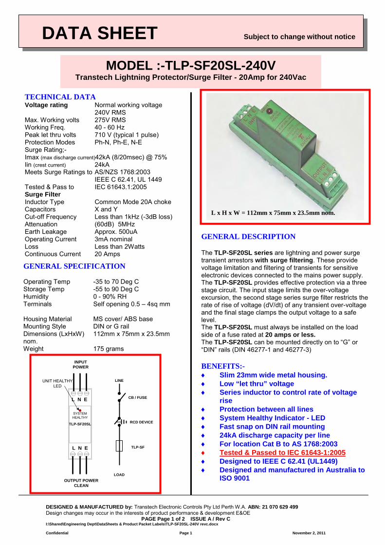
TECHNICAL DATA Voltage rating Normal working voltage
240V RMS Max. Working volts 275V RMS Working Freq. 40 - 60 Hz Peak let thru volts 710 V (typical 1 pulse) Protection Modes Ph-N, Ph-E, N-E Surge Rating;- Imax (max discharge current)42kA (8/20msec) @ 75% Iin (crest current) 24kA Meets Surge Ratings to AS/NZS 1768:2003 IEEE C 62.41, UL 1449 Tested & Pass to IEC 61643.1:2005 Surge Filter Inductor Type Common Mode 20A choke Capacitors X and Y Cut-off Frequency Less than 1kHz (-3dB loss) Attenuation (60dB) 5MHz Earth Leakage Approx. 500uA Operating Current 3mA nominal Loss Less than 2Watts Continuous Current 20 Amps GENERAL SPECIFICATION Operating Temp -35 to 70 Deg C Storage Temp -55 to 90 Deg C Humidity 0 - 90% RH Terminals Self opening 0.5 – 4sq mm Housing Material MS cover/ ABS base Mounting Style DIN or G rail Dimensions (LxHxW) 112mm x 75mm x 23.5mm nom. Weight 175 grams
GENERAL DESCRIPTION The TLP-SF20SL series are lightning and power surge transient arrestors with surge filtering. These provide voltage limitation and filtering of transients for sensitive electronic devices connected to the mains power supply. The TLP-SF20SL provides effective protection via a three stage circuit. The input stage limits the over-voltage excursion, the second stage series surge filter restricts the rate of rise of voltage (dV/dt) of any transient over-voltage and the final stage clamps the output voltage to a safe level. The TLP-SF20SL must always be installed on the load side of a fuse rated at 20 amps or less. The TLP-SF20SL can be mounted directly on to “G” or “DIN” rails (DIN 46277-1 and 46277-3) BENEFITS:- ♦ Slim 23mm wide metal housing. ♦ Low “let thru” voltage ♦ Series inductor to control rate of voltage
rise ♦ Protection between all lines ♦ System Healthy Indicator - LED ♦ Fast snap on DIN rail mounting ♦ 24kA discharge capacity per line ♦ For location Cat B to AS 1768:2003 ♦ Tested & Passed to IEC 61643-1:2005 ♦ Designed to IEEE C 62.41 (UL1449) ♦ Designed and manufactured in Australia to
ISO 9001
MODEL :-TLP-SF20SL-240V Transtech Lightning Protector/Surge Filter - 20Amp for 240Vac
L x H x W = 112mm x 75mm x 23.5mm nom.
INPUT POWER
UNIT HEALTHY LED
L N E
L N E
TLP-SF20SL
SYSTEM HEALTHY
OUTPUT POWERCLEAN
CB / FUSE
TLP-SF
RCD DEVICE
LOAD
LINE
DESIGNED & MANUFACTURED by: Transtech Electronic Controls Pty Ltd Perth W.A. ABN: 21 070 629 499 Design changes may occur in the interests of product performance & development E&OE PAGE Page 1 of 1 ISSUE A / Rev A I:\Shared\Engineering Dept\DataSheets & Product Packet Labels\TLP-SF20RI-240.doc Confidential Page 1 8/9/2012
DATA SHEET Subject to change without notice
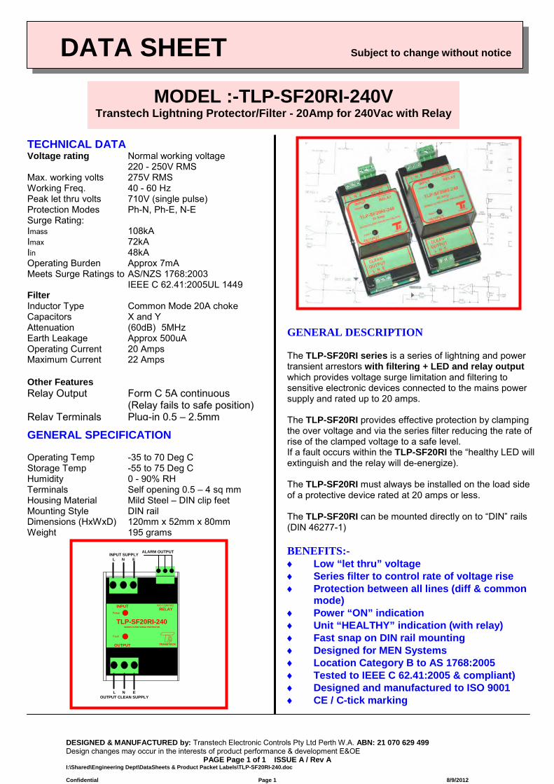
TECHNICAL DATA Voltage rating Normal working voltage
220 - 250V RMS Max. working volts 275V RMS Working Freq. 40 - 60 Hz Peak let thru volts 710V (single pulse) Protection Modes Ph-N, Ph-E, N-E Surge Rating: Imass 108kA Imax 72kA Iin 48kA Operating Burden Approx 7mA Meets Surge Ratings to AS/NZS 1768:2003 IEEE C 62.41:2005UL 1449 Filter Inductor Type Common Mode 20A choke Capacitors X and Y Attenuation (60dB) 5MHz Earth Leakage Approx 500uA Operating Current 20 Amps Maximum Current 22 Amps Other Features Relay Output Form C 5A continuous
(Relay fails to safe position) Relay Terminals Plug-in 0.5 – 2.5mm
GENERAL SPECIFICATION Operating Temp -35 to 70 Deg C Storage Temp -55 to 75 Deg C Humidity 0 - 90% RH Terminals Self opening 0.5 – 4 sq mm Housing Material Mild Steel – DIN clip feet Mounting Style DIN rail Dimensions (HxWxD) 120mm x 52mm x 80mm Weight 195 grams
GENERAL DESCRIPTION The TLP-SF20RI series is a series of lightning and power transient arrestors with filtering + LED and relay output which provides voltage surge limitation and filtering to sensitive electronic devices connected to the mains power supply and rated up to 20 amps. The TLP-SF20RI provides effective protection by clamping the over voltage and via the series filter reducing the rate of rise of the clamped voltage to a safe level. If a fault occurs within the TLP-SF20RI the “healthy LED will extinguish and the relay will de-energize). The TLP-SF20RI must always be installed on the load side of a protective device rated at 20 amps or less. The TLP-SF20RI can be mounted directly on to “DIN” rails (DIN 46277-1) BENEFITS:- ♦ Low “let thru” voltage ♦ Series filter to control rate of voltage rise ♦ Protection between all lines (diff & common
mode) ♦ Power “ON” indication ♦ Unit “HEALTHY” indication (with relay) ♦ Fast snap on DIN rail mounting ♦ Designed for MEN Systems ♦ Location Category B to AS 1768:2005 ♦ Tested to IEEE C 62.41:2005 & compliant) ♦ Designed and manufactured to ISO 9001 ♦ CE / C-tick marking
MODEL :-TLP-SF20RI-240V Transtech Lightning Protector/Filter - 20Amp for 240Vac with Relay
INPUT
OUTPUT
N/O COM N/C
Fault
Power
TLP-SF20RI-240SERIES FILTER SURGE PROTECTOR
INPUT SUPPLYL N E
L N EOUTPUT CLEAN SUPPLY
ALARM OUTPUT
RELAY
TRANSTECH
DATA SHEET
TECHNICAL DATA Voltage rating Normal working voltage
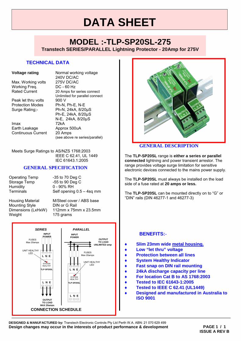
240V DC/AC Max. Working volts 275V DC/AC Working Freq. DC - 60 Hz Rated Current 20 Amps for series connect Unlimited for parallel connect Peak let thru volts 900 V Protection Modes Ph-N, Ph-E, N-E Surge Rating;- Ph-N, 24kA, 8/20μS Ph-E, 24kA, 8/20μS N-E, 24kA, 8/20μS Imax 72kA Earth Leakage Approx 500uA Continuous Current 20 Amps (see above re series/parallel) Meets Surge Ratings to AS/NZS 1768:2003 IEEE C 62.41, UL 1449 IEC 61643.1:2005 GENERAL SPECIFICATION
Operating Temp -35 to 70 Deg C Storage Temp -55 to 90 Deg C Humidity 0 - 90% RH Terminals Self opening 0.5 – 4sq mm Housing Material M/Steel cover / ABS base Mounting Style DIN or G Rail Dimensions (LxHxW) 112mm x 75mm x 23.5mm Weight 175 grams
GENERAL DESCRIPTION The TLP-SP20SL range is either a series or parallel connected lightning and power transient arrestor. The range provides voltage surge limitation for sensitive electronic devices connected to the mains power supply. The TLP-SP20SL must always be installed on the load side of a fuse rated at 20 amps or less. The TLP-SP20SL can be mounted directly on to “G” or “DIN” rails (DIN 46277-1 and 46277-3) BENEFITS:- ♦ Slim 23mm wide metal housing. ♦ Low “let thru” voltage ♦ Protection between all lines ♦ System Healthy Indicator ♦ Fast snap on DIN rail mounting ♦ 24kA discharge capacity per line ♦ For location Cat B to AS 1768:2003 ♦ Tested to IEC 61643-1:2005 ♦ Tested to IEEE C 62.41 (UL1449) ♦ Designed and manufactured in Australia to
ISO 9001
DESIGNED & MANUFACTURED by: Transtech Electronic Controls Pty Ltd Perth W.A. ABN: 21 070 629 499 Design changes may occur in the interests of product performance & development E&OE.
MODEL :-TLP-SP20SL-275 Transtech SERIES/PARALLEL Lightning Protector - 20Amp for 275V
PAGE 1 / 1 ISSUE A REV B
INPUT POWER
UNIT HEALTHY LED
L N E
L N E
TLP-SP20SL
SYSTEM HEALTHY
OUTPUT TO LOAD
MAX 20amps
INPUT POWER
UNIT HEALTHY LED
L N E
L N E
TLP-SP20SL
SYSTEM HEALTHY
OUTPUT TO LOAD
UNLIMITED amps
SERIES PARALLEL
FUSESMax 20amps
FUSESMax 20amps
CONNECTION SCHEDULE
Transtech Electronic Controls Pty Ltd ABN 21 070 629 499
Perth - Melbourne Perth Tel: (08) 9302-2044
Melbourne Tel: (03) 9330-3624 [email protected]
Low Cost Surge Protection
Also in Melbourne - Sydney – Brisbane – Adelaide TRANSTECH
TRA
NST
ECH
ELE
CTR
ON
IC C
ON
TRO
LS
ww
w.tr
anst
ech.
com
.au
DATA SHEET Subject to change without notice
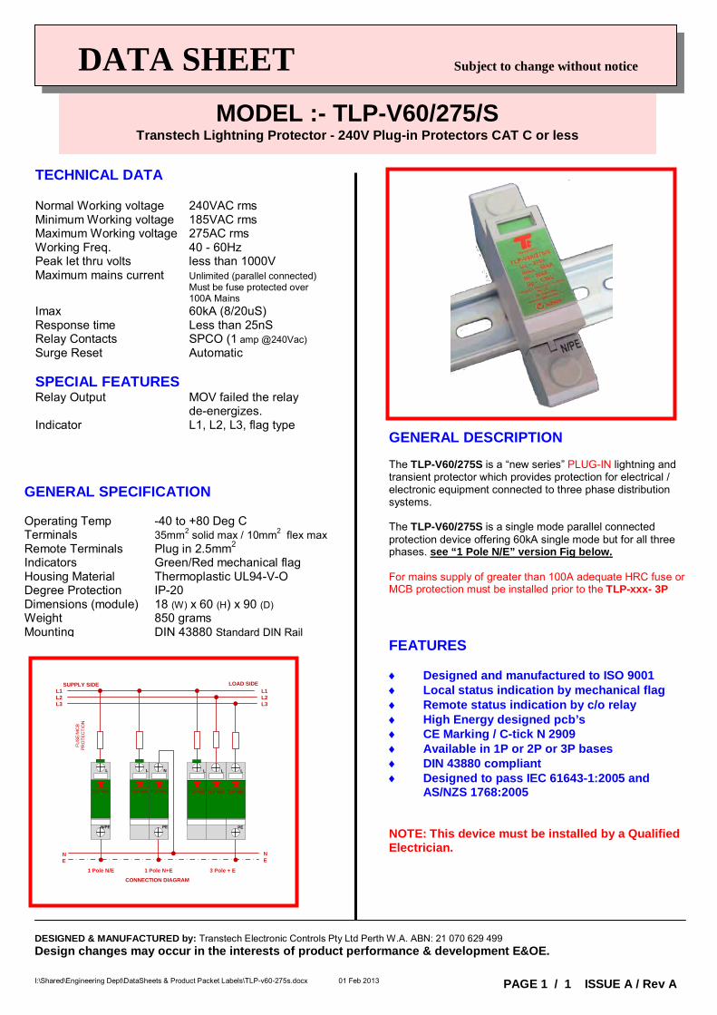
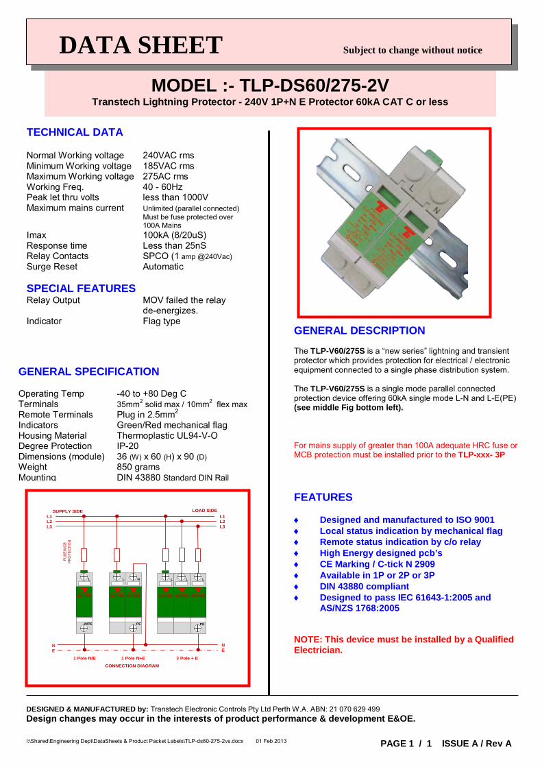
TECHNICAL DATA Normal Working voltage 240VAC rms Minimum Working voltage 185VAC rms Maximum Working voltage 275AC rms Working Freq. 40 - 60Hz Peak let thru volts less than 1000V Maximum mains current Unlimited (parallel connected) Must be fuse protected over 100A Mains Imax 60kA (8/20uS) Response time Less than 25nS Relay Contacts SPCO (1 amp @240Vac) Surge Reset Automatic SPECIAL FEATURES Relay Output MOV failed the relay de-energizes. Indicator L1, L2, L3, flag type
GENERAL SPECIFICATION Operating Temp -40 to +80 Deg C Terminals 35mm2 solid max / 10mm2 flex max Remote Terminals Plug in 2.5mm2 Indicators Green/Red mechanical flag Housing Material Thermoplastic UL94-V-O Degree Protection IP-20 Dimensions (module) 18 (W) x 60 (H) x 90 (D) Weight 850 grams Mounting DIN 43880 Standard DIN Rail
GENERAL DESCRIPTION The TLP-V60/275S is a “new series” PLUG-IN lightning and transient protector which provides protection for electrical / electronic equipment connected to three phase distribution systems. The TLP-V60/275S is a single mode parallel connected protection device offering 60kA single mode but for all three phases. see “1 Pole N/E” version Fig below. For mains supply of greater than 100A adequate HRC fuse or MCB protection must be installed prior to the TLP-xxx- 3P FEATURES ♦ Designed and manufactured to ISO 9001 ♦ Local status indication by mechanical flag ♦ Remote status indication by c/o relay ♦ High Energy designed pcb’s ♦ CE Marking / C-tick N 2909 ♦ Available in 1P or 2P or 3P bases ♦ DIN 43880 compliant ♦ Designed to pass IEC 61643-1:2005 and
AS/NZS 1768:2005 NOTE: This device must be installed by a Qualified Electrician.
MODEL :- TLP-V60/275/S Transtech Lightning Protector - 240V Plug-in Protectors CAT C or less
I:\Shared\Engineering Dept\DataSheets & Product Packet Labels\TLP-v60-275s.docx 01 Feb 2013
DESIGNED & MANUFACTURED by: Transtech Electronic Controls Pty Ltd Perth W.A. ABN: 21 070 629 499 Design changes may occur in the interests of product performance & development E&OE.
PAGE 1 / 1 ISSUE A / Rev A
SUPPLY SIDE LOAD SIDEL1L2L3
L1L2L3
CONNECTION DIAGRAM
FUS
E/M
CB
P
RO
TEC
TIO
N
TRANSTECH
TLP-V60
N/PE
L
TRANSTECH
TLP-V60TRANSTECH
TLP-V60
L L
TRANSTECH
TLP-V60
PE
L
TRANSTECH
TLP-V60TRANSTECH
TLP-V60
PE
L N
1 Pole N/E 3 Pole + E1 Pole N+E
NE
NE
DATA SHEET Subject to change without notice
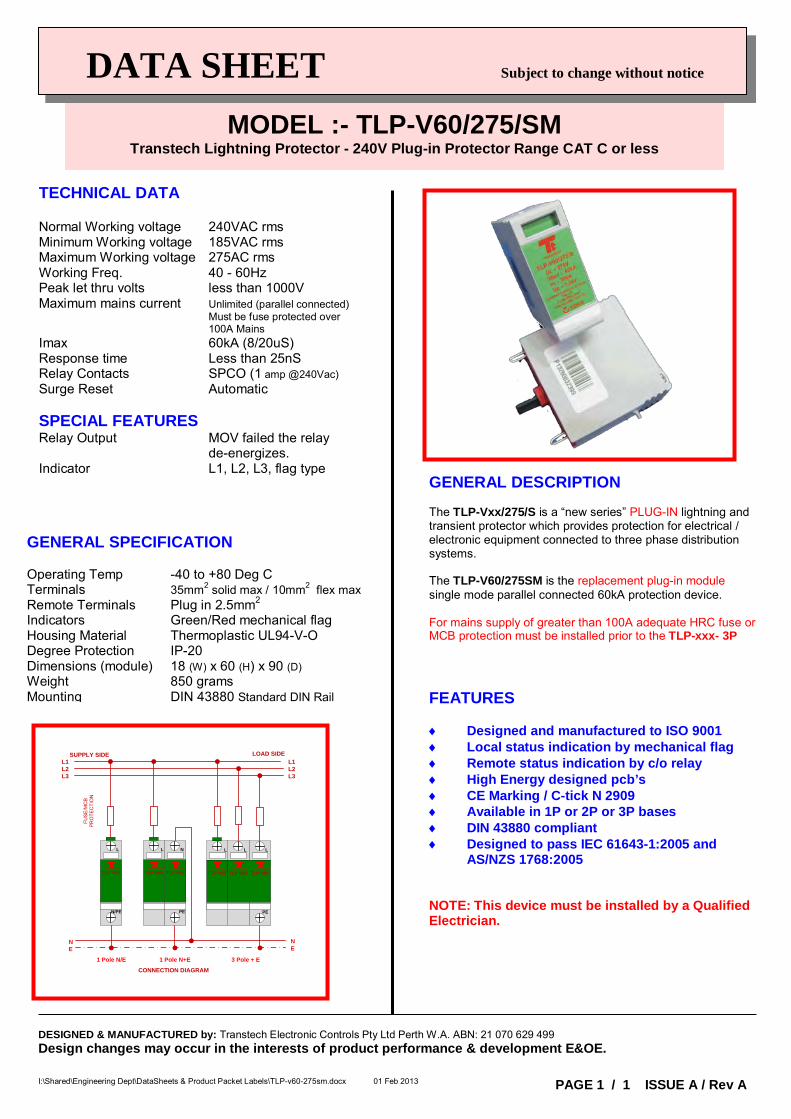
TECHNICAL DATA Normal Working voltage 240VAC rms Minimum Working voltage 185VAC rms Maximum Working voltage 275AC rms Working Freq. 40 - 60Hz Peak let thru volts less than 1000V Maximum mains current Unlimited (parallel connected) Must be fuse protected over 100A Mains Imax 60kA (8/20uS) Response time Less than 25nS Relay Contacts SPCO (1 amp @240Vac) Surge Reset Automatic SPECIAL FEATURES Relay Output MOV failed the relay de-energizes. Indicator L1, L2, L3, flag type
GENERAL SPECIFICATION Operating Temp -40 to +80 Deg C Terminals 35mm2 solid max / 10mm2 flex max Remote Terminals Plug in 2.5mm2 Indicators Green/Red mechanical flag Housing Material Thermoplastic UL94-V-O Degree Protection IP-20 Dimensions (module) 18 (W) x 60 (H) x 90 (D) Weight 850 grams Mounting DIN 43880 Standard DIN Rail
GENERAL DESCRIPTION The TLP-Vxx/275/S is a “new series” PLUG-IN lightning and transient protector which provides protection for electrical / electronic equipment connected to three phase distribution systems. The TLP-V60/275SM is the replacement plug-in module single mode parallel connected 60kA protection device. For mains supply of greater than 100A adequate HRC fuse or MCB protection must be installed prior to the TLP-xxx- 3P FEATURES ♦ Designed and manufactured to ISO 9001 ♦ Local status indication by mechanical flag ♦ Remote status indication by c/o relay ♦ High Energy designed pcb’s ♦ CE Marking / C-tick N 2909 ♦ Available in 1P or 2P or 3P bases ♦ DIN 43880 compliant ♦ Designed to pass IEC 61643-1:2005 and
AS/NZS 1768:2005 NOTE: This device must be installed by a Qualified Electrician.
MODEL :- TLP-V60/275/SM Transtech Lightning Protector - 240V Plug-in Protector Range CAT C or less
I:\Shared\Engineering Dept\DataSheets & Product Packet Labels\TLP-v60-275sm.docx 01 Feb 2013
DESIGNED & MANUFACTURED by: Transtech Electronic Controls Pty Ltd Perth W.A. ABN: 21 070 629 499 Design changes may occur in the interests of product performance & development E&OE.
PAGE 1 / 1 ISSUE A / Rev A
SUPPLY SIDE LOAD SIDEL1L2L3
L1L2L3
CONNECTION DIAGRAM
FUS
E/M
CB
P
RO
TEC
TIO
N
TRANSTECH
TLP-V60
N/PE
L
TRANSTECH
TLP-V60TRANSTECH
TLP-V60
L L
TRANSTECH
TLP-V60
PE
L
TRANSTECH
TLP-V60TRANSTECH
TLP-V60
PE
L N
1 Pole N/E 3 Pole + E1 Pole N+E
NE
NE
DATA SHEET Subject to change without notice
TECHNICAL DATA Normal Working voltage 240VAC rms Minimum Working voltage 185VAC rms Maximum Working voltage 275AC rms Working Freq. 40 - 60Hz Peak let thru volts less than 1000V Maximum mains current Unlimited (parallel connected) Must be fuse protected over 100A Mains Imax 100kA (8/20uS) Response time Less than 25nS Relay Contacts SPCO (1 amp @240Vac) Surge Reset Automatic SPECIAL FEATURES Relay Output MOV failed the relay de-energizes. Indicator Flag type
GENERAL SPECIFICATION Operating Temp -40 to +80 Deg C Terminals 35mm2 solid max / 10mm2 flex max Remote Terminals Plug in 2.5mm2 Indicators Green/Red mechanical flag Housing Material Thermoplastic UL94-V-O Degree Protection IP-20 Dimensions (module) 36 (W) x 60 (H) x 90 (D) Weight 850 grams Mounting DIN 43880 Standard DIN Rail
GENERAL DESCRIPTION The TLP-V60/275S is a “new series” lightning and transient protector which provides protection for electrical / electronic equipment connected to a single phase distribution system. The TLP-V60/275S is a single mode parallel connected protection device offering 60kA single mode L-N and L-E(PE) (see middle Fig bottom left). For mains supply of greater than 100A adequate HRC fuse or MCB protection must be installed prior to the TLP-xxx- 3P FEATURES ♦ Designed and manufactured to ISO 9001 ♦ Local status indication by mechanical flag ♦ Remote status indication by c/o relay ♦ High Energy designed pcb’s ♦ CE Marking / C-tick N 2909 ♦ Available in 1P or 2P or 3P ♦ DIN 43880 compliant ♦ Designed to pass IEC 61643-1:2005 and
AS/NZS 1768:2005 NOTE: This device must be installed by a Qualified Electrician.
MODEL :- TLP-DS60/275-2V Transtech Lightning Protector - 240V 1P+N E Protector 60kA CAT C or less
I:\Shared\Engineering Dept\DataSheets & Product Packet Labels\TLP-ds60-275-2vs.docx 01 Feb 2013
DESIGNED & MANUFACTURED by: Transtech Electronic Controls Pty Ltd Perth W.A. ABN: 21 070 629 499 Design changes may occur in the interests of product performance & development E&OE.
PAGE 1 / 1 ISSUE A / Rev A
SUPPLY SIDE LOAD SIDEL1L2L3
L1L2L3
CONNECTION DIAGRAM
FUSE
/MC
B PR
OTE
CTI
ON
TRANSTECH
TLP-V60
N/PE
L
TRANSTECH
TLP-V60TRANSTECH
TLP-V60
L L
TRANSTECH
TLP-V60
PE
L
TRANSTECH
TLP-V60TRANSTECH
TLP-V60
PE
L N
1 Pole N/E 3 Pole + E1 Pole N+E
NE
NE

DATA SHEET Subject to change without notice
TECHNICAL DATA Normal Working voltage 240VAC rms Minimum Working voltage 185VAC rms Maximum Working voltage 275AC rms Working Freq. 40 - 60Hz Peak let thru volts less than 1000V Maximum mains current Unlimited (parallel connected) Must be fuse protected over 100A Mains Imax 100kA (8/20uS) Response time Less than 25nS Relay Contacts SPCO (1 amp @240Vac) Surge Reset Automatic SPECIAL FEATURES Relay Output MOV failed the relay de-energizes. Indicator Flag type
GENERAL SPECIFICATION Operating Temp -40 to +80 Deg C Terminals 35mm2 solid max / 10mm2 flex max Remote Terminals Plug in 2.5mm2 Indicators Green/Red mechanical flag Housing Material Thermoplastic UL94-V-O Degree Protection IP-20 Dimensions (module) 36 (W) x 60 (H) x 90 (D) Weight 850 grams Mounting DIN 43880 Standard DIN Rail
GENERAL DESCRIPTION The TLP-V100/275S is a “new series” lightning and transient protector which provides protection for electrical / electronic equipment connected to a single phase distribution system. The TLP-V100/275S is a single mode parallel connected protection device offering 100kA single mode (see Fig bottom left). For mains supply of greater than 100A adequate HRC fuse or MCB protection must be installed prior to the TLP-xxx- 3P FEATURES ♦ Designed and manufactured to ISO 9001 ♦ Local status indication by mechanical flag ♦ Remote status indication by c/o relay ♦ High Energy designed pcb’s ♦ CE Marking / C-tick N 2909 ♦ Available in 1P or 2P or 3P ♦ DIN 43880 compliant ♦ Designed to pass IEC 61643-1:2005 and
AS/NZS 1768:2005 NOTE: This device must be installed by a Qualified Electrician.
MODEL :- TLP-V100/275 Transtech Lightning Protector - 240V 1P Protector 100kA CAT C or less
I:\Shared\Engineering Dept\DataSheets & Product Packet Labels\TLP-v100-275.docx 01 Feb 2013
DESIGNED & MANUFACTURED by: Transtech Electronic Controls Pty Ltd Perth W.A. ABN: 21 070 629 499 Design changes may occur in the interests of product performance & development E&OE.
PAGE 1 / 1 ISSUE A / Rev A
SUPPLY SIDE LOAD SIDEL1L2L3
L1L2L3
CONNECTION DIAGRAM
FUSE
/MCB
PR
OT
ECTI
ON
1 Pole N+E
NE
NE
TRA NST ECH
TLP-V100TRA NST ECH
TLP-V100
L L
DATA SHEET Subject to change without notice
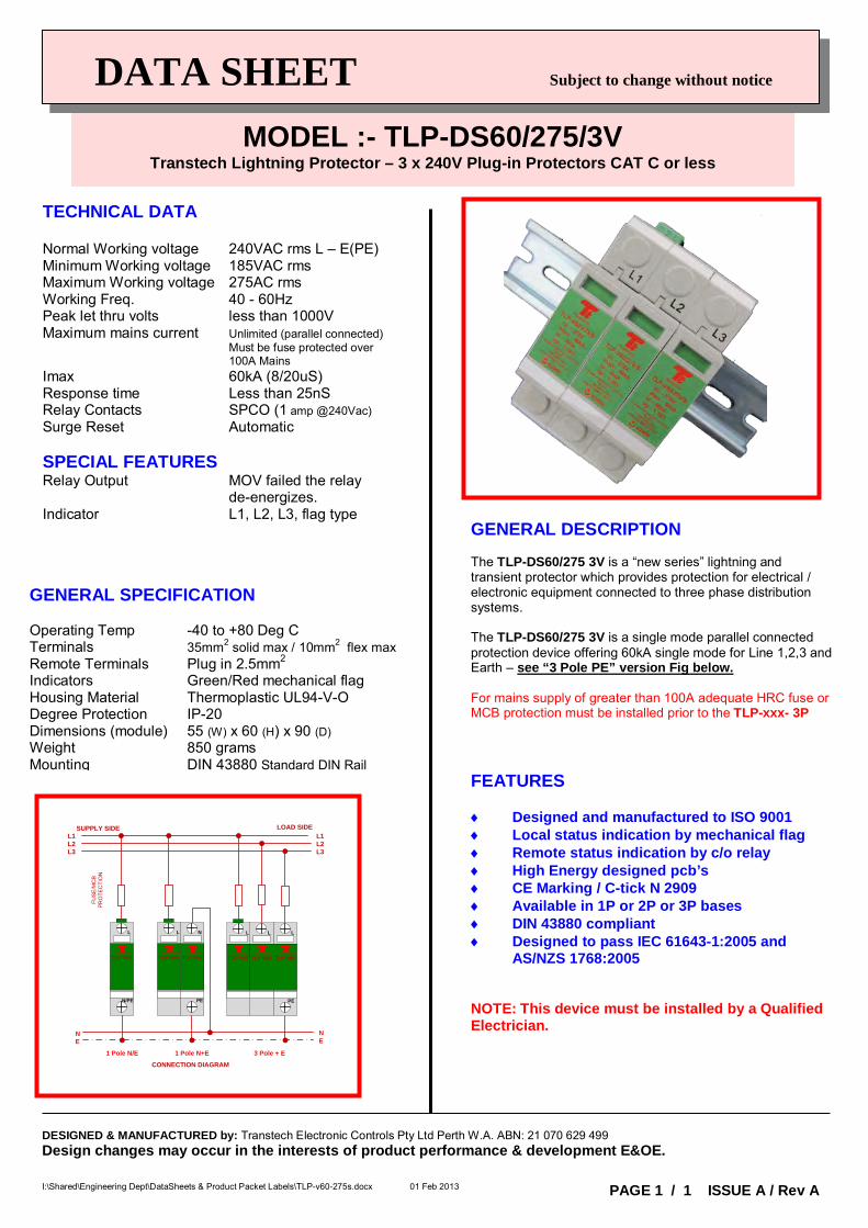
TECHNICAL DATA Normal Working voltage 240VAC rms L – E(PE) Minimum Working voltage 185VAC rms Maximum Working voltage 275AC rms Working Freq. 40 - 60Hz Peak let thru volts less than 1000V Maximum mains current Unlimited (parallel connected) Must be fuse protected over 100A Mains Imax 60kA (8/20uS) Response time Less than 25nS Relay Contacts SPCO (1 amp @240Vac) Surge Reset Automatic SPECIAL FEATURES Relay Output MOV failed the relay de-energizes. Indicator L1, L2, L3, flag type
GENERAL SPECIFICATION Operating Temp -40 to +80 Deg C Terminals 35mm2 solid max / 10mm2 flex max Remote Terminals Plug in 2.5mm2 Indicators Green/Red mechanical flag Housing Material Thermoplastic UL94-V-O Degree Protection IP-20 Dimensions (module) 55 (W) x 60 (H) x 90 (D) Weight 850 grams Mounting DIN 43880 Standard DIN Rail
GENERAL DESCRIPTION The TLP-DS60/275 3V is a “new series” lightning and transient protector which provides protection for electrical / electronic equipment connected to three phase distribution systems. The TLP-DS60/275 3V is a single mode parallel connected protection device offering 60kA single mode for Line 1,2,3 and Earth – see “3 Pole PE” version Fig below. For mains supply of greater than 100A adequate HRC fuse or MCB protection must be installed prior to the TLP-xxx- 3P FEATURES ♦ Designed and manufactured to ISO 9001 ♦ Local status indication by mechanical flag ♦ Remote status indication by c/o relay ♦ High Energy designed pcb’s ♦ CE Marking / C-tick N 2909 ♦ Available in 1P or 2P or 3P bases ♦ DIN 43880 compliant ♦ Designed to pass IEC 61643-1:2005 and
AS/NZS 1768:2005 NOTE: This device must be installed by a Qualified Electrician.
MODEL :- TLP-DS60/275/3V Transtech Lightning Protector – 3 x 240V Plug-in Protectors CAT C or less
I:\Shared\Engineering Dept\DataSheets & Product Packet Labels\TLP-v60-275s.docx 01 Feb 2013
DESIGNED & MANUFACTURED by: Transtech Electronic Controls Pty Ltd Perth W.A. ABN: 21 070 629 499 Design changes may occur in the interests of product performance & development E&OE.
PAGE 1 / 1 ISSUE A / Rev A
SUPPLY SIDE LOAD SIDEL1L2L3
L1L2L3
CONNECTION DIAGRAM
FUS
E/M
CB
P
RO
TEC
TIO
N
TRANSTECH
TLP-V60
N/PE
L
TRANSTECH
TLP-V60TRANSTECH
TLP-V60
L L
TRANSTECH
TLP-V60
PE
L
TRANSTECH
TLP-V60TRANSTECH
TLP-V60
PE
L N
1 Pole N/E 3 Pole + E1 Pole N+E
NE
NE
Transtech Electronic Controls Pty Ltd ABN 21 070 629 499
Perth - Melbourne Perth Tel: (08) 9302-2044
Melbourne Tel: (03) 9330-3624 [email protected]
Electronic Transient Surge Protection
LOW VOLTAGE & BUS PROTECTORS – Cat B or A
Also in Melbourne - Sydney – Brisbane – Adelaide TRANSTECH
TRA
NST
ECH
ELE
CTR
ON
IC C
ON
TRO
LS
ww
w.tr
anst
ech.
com
.au
NEW
DESIGNED & MANUFACTURED in AUSTRALIA by: Transtech Electronic Controls Pty Ltd Perth W.A. ABN: 21 070 629 499 Design changes may occur in the interests of product performance & development E&OE Page 1 of 1 ISSUE A / Rev A I:\Shared\Engineering Dept\DataSheets & Product Packet Labels\TLP-SL62-30D new.doc Confidential August 23, 2011
DATA SHEET Subject to change without notice
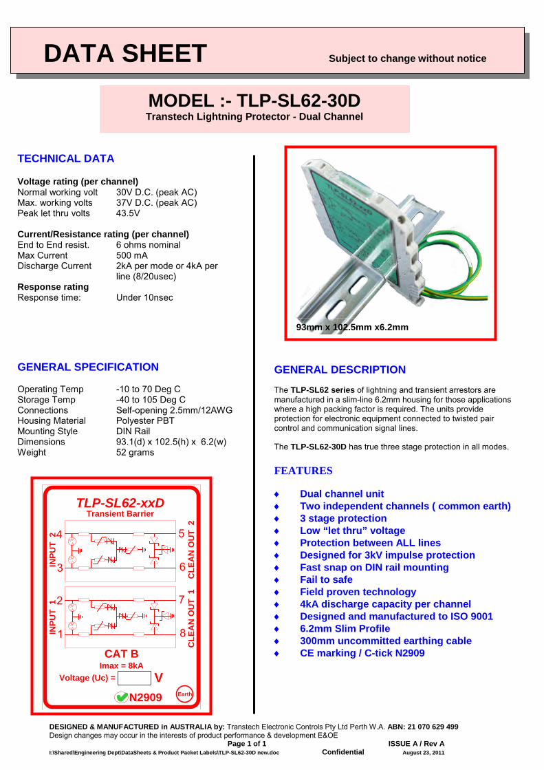
TECHNICAL DATA Voltage rating (per channel) Normal working volt 30V D.C. (peak AC) Max. working volts 37V D.C. (peak AC) Peak let thru volts 43.5V Current/Resistance rating (per channel) End to End resist. 6 ohms nominal Max Current 500 mA Discharge Current 2kA per mode or 4kA per
line (8/20usec) Response rating Response time: Under 10nsec
GENERAL SPECIFICATION Operating Temp -10 to 70 Deg C Storage Temp -40 to 105 Deg C Connections Self-opening 2.5mm/12AWG Housing Material Polyester PBT Mounting Style DIN Rail Dimensions 93.1(d) x 102.5(h) x 6.2(w) Weight 52 grams
GENERAL DESCRIPTION The TLP-SL62 series of lightning and transient arrestors are manufactured in a slim-line 6.2mm housing for those applications where a high packing factor is required. The units provide protection for electronic equipment connected to twisted pair control and communication signal lines. The TLP-SL62-30D has true three stage protection in all modes. FEATURES ♦ Dual channel unit ♦ Two independent channels ( common earth) ♦ 3 stage protection ♦ Low “let thru” voltage ♦ Protection between ALL lines ♦ Designed for 3kV impulse protection ♦ Fast snap on DIN rail mounting ♦ Fail to safe ♦ Field proven technology ♦ 4kA discharge capacity per channel ♦ Designed and manufactured to ISO 9001 ♦ 6.2mm Slim Profile ♦ 300mm uncommitted earthing cable ♦ CE marking / C-tick N2909
MODEL :- TLP-SL62-30D Transtech Lightning Protector - Dual Channel
N2909
2
8
7
1
4
6
5
3
TLP-SL62-xxD
INPU
T 2
CLE
AN
OU
T 1
INPU
T 1
CLE
AN
OU
T 2
Transient Barrier
Earth
CAT BImax = 8kA
Voltage (Uc) = V
93mm x 102.5mm x6.2mm
DESIGNED & MANUFACTURED in AUSTRALIA by: Transtech Electronic Controls Pty Ltd Perth W.A. ABN: 21 070 629 499 Design changes may occur in the interests of product performance & development E&OE Page 1 of 1 ISSUE A / Rev A I:\Shared\Engineering Dept\DataSheets & Product Packet Labels\TLP-SL12-xx.docx Confidential November 6, 2012
DATA SHEET Subject to change without notice
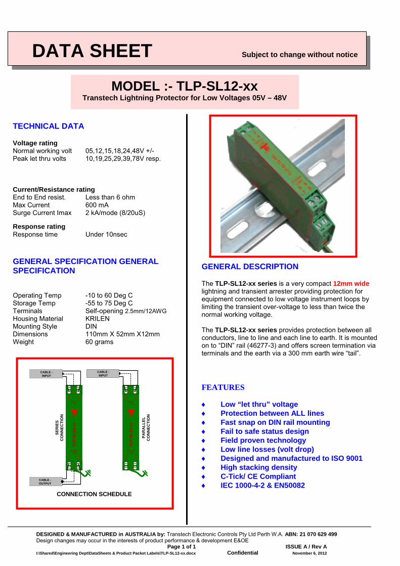
TECHNICAL DATA Voltage rating Normal working volt 05,12,15,18,24,48V +/- Peak let thru volts 10,19,25,29,39,78V resp. Current/Resistance rating End to End resist. Less than 6 ohm Max Current 600 mA Surge Current Imax 2 kA/mode (8/20uS) Response rating Response time Under 10nsec
GENERAL SPECIFICATION GENERAL SPECIFICATION Operating Temp -10 to 60 Deg C Storage Temp -55 to 75 Deg C Terminals Self-opening 2.5mm/12AWG Housing Material KRILEN Mounting Style DIN Dimensions 110mm X 52mm X12mm Weight 60 grams
GENERAL DESCRIPTION The TLP-SL12-xx series is a very compact 12mm wide lightning and transient arrester providing protection for equipment connected to low voltage instrument loops by limiting the transient over-voltage to less than twice the normal working voltage. The TLP-SL12-xx series provides protection between all conductors, line to line and each line to earth. It is mounted on to “DIN” rail (46277-3) and offers screen termination via terminals and the earth via a 300 mm earth wire “tail”. FEATURES ♦ Low “let thru” voltage ♦ Protection between ALL lines ♦ Fast snap on DIN rail mounting ♦ Fail to safe status design ♦ Field proven technology ♦ Low line losses (volt drop) ♦ Designed and manufactured to ISO 9001 ♦ High stacking density ♦ C-Tick/ CE Compliant ♦ IEC 1000-4-2 & EN50082
MODEL :- TLP-SL12-xx Transtech Lightning Protector for Low Voltages 05V – 48V
TRANSTECH
INPUT LINE
TLP-
SL12
-xx
1 23 4
1 2
3 4
5 6
7 8
OUTPUT LINE
5 67 8
TRANSTECH
INPUT LINE
TLP-
SL12
-xx
1 23 4
1 2
3 4
5 6
7 8
OUTPUT LINE
5 67 8
CABLE - OUTPUT
CABLE - INPUT
CABLE - INPUT
CONNECTION SCHEDULE
SER
IES
CO
NN
ECTI
ON
PAR
ALL
ELC
ON
NEC
TIO
N
DATA SHEET Subject to change without notice
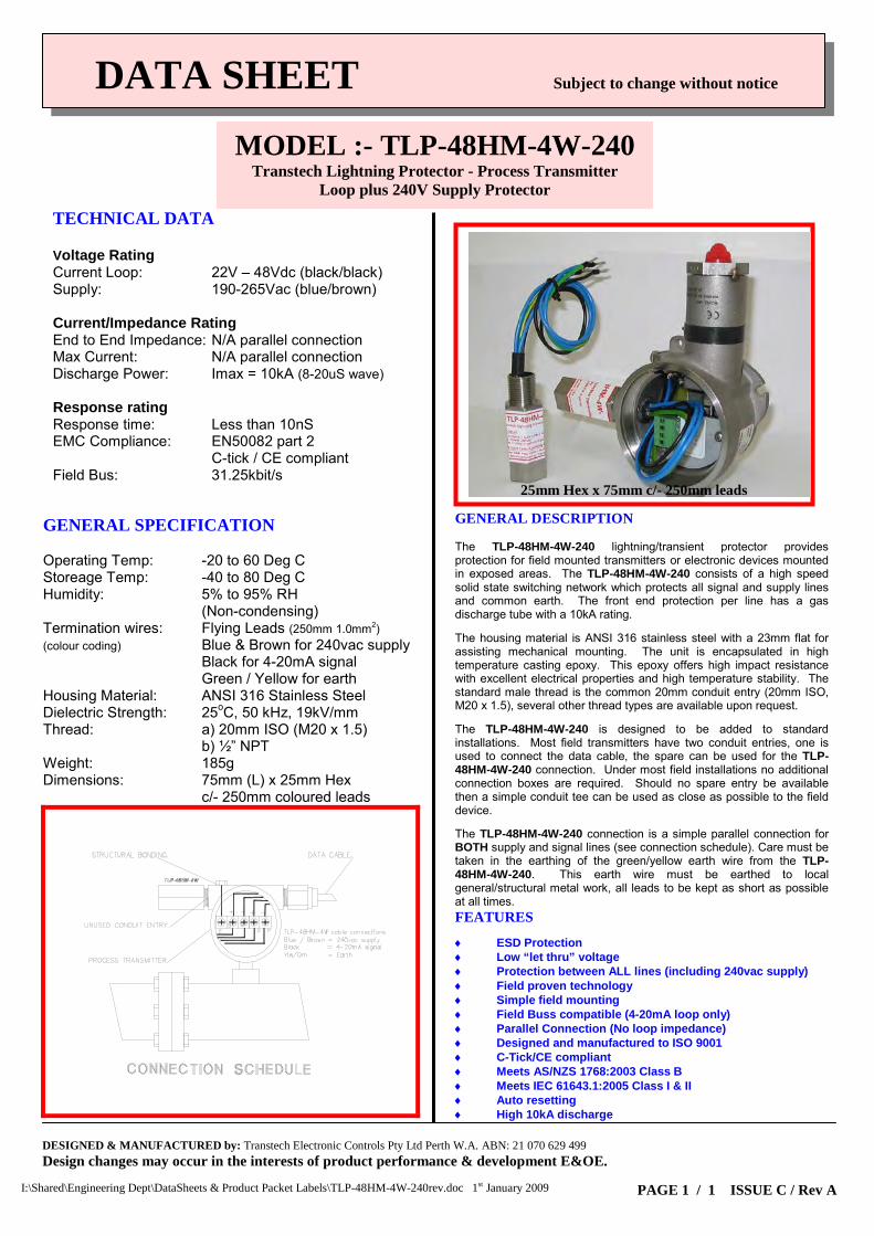
TECHNICAL DATA Voltage Rating Current Loop: 22V – 48Vdc (black/black) Supply: 190-265Vac (blue/brown) Current/Impedance Rating End to End Impedance: N/A parallel connection Max Current: N/A parallel connection Discharge Power: Imax = 10kA (8-20uS wave) Response rating Response time: Less than 10nS EMC Compliance: EN50082 part 2 C-tick / CE compliant Field Bus: 31.25kbit/s
GENERAL SPECIFICATION Operating Temp: -20 to 60 Deg C Storeage Temp: -40 to 80 Deg C Humidity: 5% to 95% RH (Non-condensing) Termination wires: Flying Leads (250mm 1.0mm2) (colour coding) Blue & Brown for 240vac supply Black for 4-20mA signal Green / Yellow for earth Housing Material: ANSI 316 Stainless Steel Dielectric Strength: 25oC, 50 kHz, 19kV/mm Thread: a) 20mm ISO (M20 x 1.5) b) ½” NPT Weight: 185g Dimensions: 75mm (L) x 25mm Hex c/- 250mm coloured leads
GENERAL DESCRIPTION The TLP-48HM-4W-240 lightning/transient protector provides protection for field mounted transmitters or electronic devices mounted in exposed areas. The TLP-48HM-4W-240 consists of a high speed solid state switching network which protects all signal and supply lines and common earth. The front end protection per line has a gas discharge tube with a 10kA rating. The housing material is ANSI 316 stainless steel with a 23mm flat for assisting mechanical mounting. The unit is encapsulated in high temperature casting epoxy. This epoxy offers high impact resistance with excellent electrical properties and high temperature stability. The standard male thread is the common 20mm conduit entry (20mm ISO, M20 x 1.5), several other thread types are available upon request. The TLP-48HM-4W-240 is designed to be added to standard installations. Most field transmitters have two conduit entries, one is used to connect the data cable, the spare can be used for the TLP-48HM-4W-240 connection. Under most field installations no additional connection boxes are required. Should no spare entry be available then a simple conduit tee can be used as close as possible to the field device. The TLP-48HM-4W-240 connection is a simple parallel connection for BOTH supply and signal lines (see connection schedule). Care must be taken in the earthing of the green/yellow earth wire from the TLP-48HM-4W-240. This earth wire must be earthed to local general/structural metal work, all leads to be kept as short as possible at all times. FEATURES ♦ ESD Protection ♦ Low “let thru” voltage ♦ Protection between ALL lines (including 240vac supply) ♦ Field proven technology ♦ Simple field mounting ♦ Field Buss compatible (4-20mA loop only) ♦ Parallel Connection (No loop impedance) ♦ Designed and manufactured to ISO 9001 ♦ C-Tick/CE compliant ♦ Meets AS/NZS 1768:2003 Class B ♦ Meets IEC 61643.1:2005 Class I & II ♦ Auto resetting ♦ High 10kA discharge
MODEL :- TLP-48HM-4W-240 Transtech Lightning Protector - Process Transmitter
Loop plus 240V Supply Protector
DESIGNED & MANUFACTURED by: Transtech Electronic Controls Pty Ltd Perth W.A. ABN: 21 070 629 499 Design changes may occur in the interests of product performance & development E&OE. I:\Shared\Engineering Dept\DataSheets & Product Packet Labels\TLP-48HM-4W-240rev.doc 1st January 2009
PAGE 1 / 1 ISSUE C / Rev A
25mm Hex x 75mm c/- 250mm leads
DESIGNED & MANUFACTURED in AUSTRALIA by: Transtech Electronic Controls Pty Ltd Perth W.A. ABN: 21 070 629 499 Design changes may occur in the interests of product performance & development E&OE Page 1 of 1 ISSUE A / Rev A I:\Shared\Engineering Dept\DataSheets & Product Packet Labels\TLP-SL12-RS485MB.docx Confidential November 6, 2012
DATA SHEET Subject to change without notice
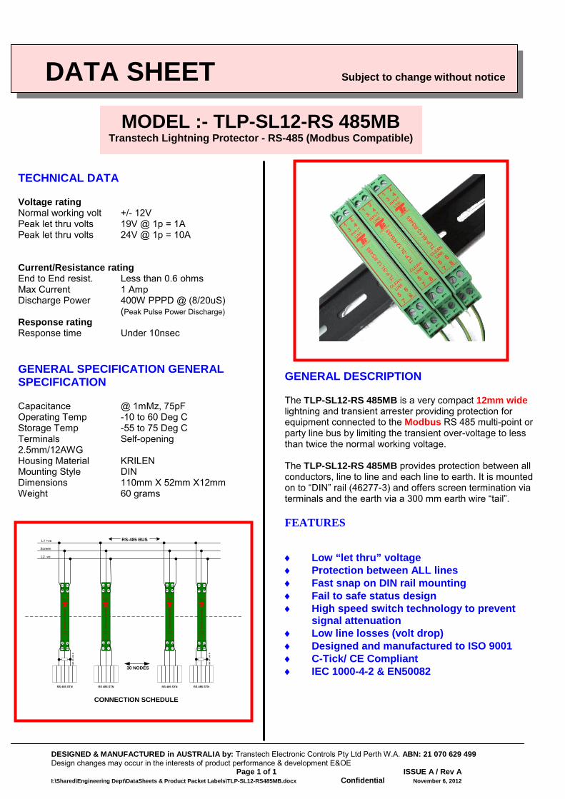
TECHNICAL DATA Voltage rating Normal working volt +/- 12V Peak let thru volts 19V @ 1p = 1A Peak let thru volts 24V @ 1p = 10A Current/Resistance rating End to End resist. Less than 0.6 ohms Max Current 1 Amp Discharge Power 400W PPPD @ (8/20uS) (Peak Pulse Power Discharge) Response rating Response time Under 10nsec
GENERAL SPECIFICATION GENERAL SPECIFICATION Capacitance @ 1mMz, 75pF Operating Temp -10 to 60 Deg C Storage Temp -55 to 75 Deg C Terminals Self-opening 2.5mm/12AWG Housing Material KRILEN Mounting Style DIN Dimensions 110mm X 52mm X12mm Weight 60 grams
GENERAL DESCRIPTION The TLP-SL12-RS 485MB is a very compact 12mm wide lightning and transient arrester providing protection for equipment connected to the Modbus RS 485 multi-point or party line bus by limiting the transient over-voltage to less than twice the normal working voltage. The TLP-SL12-RS 485MB provides protection between all conductors, line to line and each line to earth. It is mounted on to “DIN” rail (46277-3) and offers screen termination via terminals and the earth via a 300 mm earth wire “tail”. FEATURES ♦ Low “let thru” voltage ♦ Protection between ALL lines ♦ Fast snap on DIN rail mounting ♦ Fail to safe status design ♦ High speed switch technology to prevent
signal attenuation ♦ Low line losses (volt drop) ♦ Designed and manufactured to ISO 9001 ♦ C-Tick/ CE Compliant ♦ IEC 1000-4-2 & EN50082
MODEL :- TLP-SL12-RS 485MB Transtech Lightning Protector - RS-485 (Modbus Compatible)
RS 485 STN
END
OF
LIN
E R
RS 485 STN RS 485 STN RS 485 STN
END
OF
LIN
E R
30 NODES
CONNECTION SCHEDULE
RS-485 BUSL1 +ve
Screen
L2 -ve
TRANSTECH
INPUT LINE
CLEAN LINE
TLP-
SL12
-RS4
85
1 23 4
5 67 8
TRANSTECH
INPUT LINE
CLEAN LINE
TLP-
SL12
-RS4
85
1 23 4
5 67 8
TRANSTECH
INPUT LINE
CLEAN LINE
TLP-
SL12
-RS4
85
1 23 4
5 67 8
TRANSTECH
INPUT LINE
CLEAN LINE
TLP-
SL12
-RS4
85
1 23 4
5 67 8
DESIGNED & MANUFACTURED in AUSTRALIA by: Transtech Electronic Controls Pty Ltd Perth W.A. ABN: 21 070 629 499 Design changes may occur in the interests of product performance & development E&OE Page 1 of 1 ISSUE A / Rev A I:\Shared\Engineering Dept\DataSheets & Product Packet Labels\TLP-DNET new.docx Confidential August 25, 2011
DATA SHEET Subject to change without notice
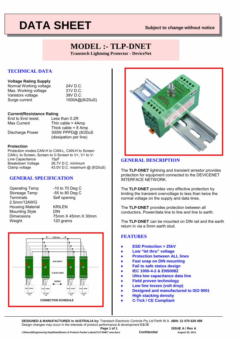
TECHNICAL DATA Voltage Rating Supply Normal Working voltage 24V D.C. Max. Working voltage 31V D.C. Varistors voltage 39V D.C. Surge current 1000A@(8/20uS) Current/Resistance Rating End to End resist. Less than 0.2R Max Current Thin cable = 4Amp Thick cable = 8 Amp Discharge Power 300W PPPD@ (8/20uS
(dissipation per line) Protection Protection modes CAN-H to CAN-L, CAN-H to Screen CAN-L to Screen, Screen to V-Screen to V+, V+ to V- Line Capacitance 15pF Breakdown Voltage 26.7V D.C. minimum Clamp voltage 43.0V D.C. maximum @ (8/20uS)
GENERAL SPECIFICATION Operating Temp -10 to 70 Deg C Storeage Temp -55 to 80 Deg C Terminals Self opening 2.5mm/12AWG Housing Material KRILEN Mounting Style DIN Dimensions 75mm X 45mm X 30mm Weight 120 grams
GENERAL DESCRIPTION The TLP-DNET lightning and transient arrestor provides protection for equipment connected to the DEVICENET INTERFACE NETWORK. The TLP-DNET provides very effective protection by limiting the transient overvoltage to less than twice the normal voltage on the supply and data lines. The TLP-DNET provides protection between all conductors, Power/data line to line and line to earth. The TLP-DNET can be mounted on DIN rail and the earth return in via a 5mm earth stud. FEATURES ♦ ESD Protection > 25kV ♦ Low “let thru” voltage ♦ Protection between ALL lines ♦ Fast snap on DIN mounting ♦ Fail to safe status design ♦ IEC 1000-4-2 & EN50082 ♦ Ultra low capacitance data line ♦ Field proven technology ♦ Low line losses (volt drop) ♦ Designed and manufactured to ISO 9001 ♦ High stacking density ♦ C-Tick / CE Compliant
MODEL :- TLP-DNET Transtech Lightning Protector - DeviceNet
NODES
CONNECTION SCHEDULE
CAN bus
TRANSTECH
1 2 3 4 5
BUS CONNECTION
SUPPLY/CONTROLLER
TLP-DNET
V1 L S H V+
X
1 2 3 4 5 V1 L S H V+
TRANSTECH
1 2 3 4 5
BUS CONNECTION
SUPPLY/CONTROLLER
TLP-DNET
V1 L S H V+
X
1 2 3 4 5 V1 L S H V+
TRANSTECH
1 2 3 4 5
BUS CONNECTION
SUPPLY/CONTROLLER
TLP-DNET
V1 L S H V+
X
1 2 3 4 5 V1 L S H V+
TRANSTECH
1 2 3 4 5
BUS CONNECTION
SUPPLY/CONTROLLER
TLP-DNET
V1 L S H V+
X
1 2 3 4 5 V1 L S H V+
DeviceNET STN
NODEPSU
DeviceNET STN
NODEPSU
DeviceNET STN
NODEPSU
DeviceNET STN
NODEPSU
BUS INPUT
CLEAN LINES
Transtech Electronic Controls Pty Ltd ABN 21 070 629 499
Perth - Melbourne Perth Tel: (08) 9302-2044
Melbourne Tel: (03) 9330-3624 [email protected]
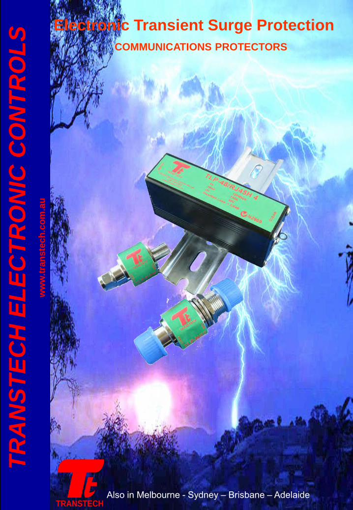
Electronic Transient Surge Protection COMMUNICATIONS PROTECTORS
Also in Melbourne - Sydney – Brisbane – Adelaide TRANSTECH
TRA
NST
ECH
ELE
CTR
ON
IC C
ON
TRO
LS
ww
w.tr
anst
ech.
com
.au
IMPORTED in AUSTRALIA by: Transtech Electronic Controls Pty Ltd Perth W.A. ABN: 21 070 629 499 Design changes may occur in the interests of product performance & development E&OE Page 1 of 1 ISSUE A / Rev A I:\Shared\Engineering Dept\DataSheets & Product Packet Labels\TLP-48_RJ45H4 new.docx Confidential August 25, 2011
DATA SHEET Subject to change without notice
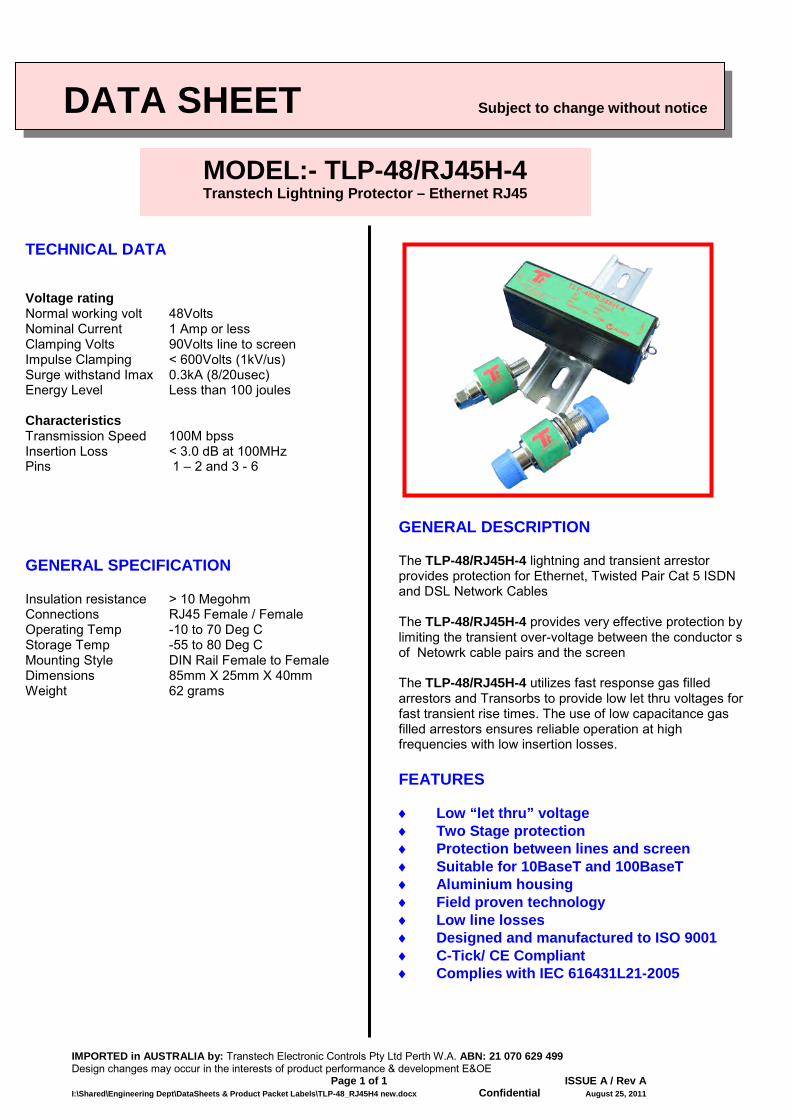
TECHNICAL DATA Voltage rating Normal working volt 48Volts Nominal Current 1 Amp or less Clamping Volts 90Volts line to screen Impulse Clamping < 600Volts (1kV/us) Surge withstand Imax 0.3kA (8/20usec) Energy Level Less than 100 joules Characteristics Transmission Speed 100M bpss Insertion Loss < 3.0 dB at 100MHz Pins 1 – 2 and 3 - 6
GENERAL SPECIFICATION Insulation resistance > 10 Megohm Connections RJ45 Female / Female Operating Temp -10 to 70 Deg C Storage Temp -55 to 80 Deg C Mounting Style DIN Rail Female to Female Dimensions 85mm X 25mm X 40mm Weight 62 grams
GENERAL DESCRIPTION The TLP-48/RJ45H-4 lightning and transient arrestor provides protection for Ethernet, Twisted Pair Cat 5 ISDN and DSL Network Cables The TLP-48/RJ45H-4 provides very effective protection by limiting the transient over-voltage between the conductor s of Netowrk cable pairs and the screen The TLP-48/RJ45H-4 utilizes fast response gas filled arrestors and Transorbs to provide low let thru voltages for fast transient rise times. The use of low capacitance gas filled arrestors ensures reliable operation at high frequencies with low insertion losses. FEATURES ♦ Low “let thru” voltage ♦ Two Stage protection ♦ Protection between lines and screen ♦ Suitable for 10BaseT and 100BaseT ♦ Aluminium housing ♦ Field proven technology ♦ Low line losses ♦ Designed and manufactured to ISO 9001 ♦ C-Tick/ CE Compliant ♦ Complies with IEC 616431L21-2005
MODEL:- TLP-48/RJ45H-4 Transtech Lightning Protector – Ethernet RJ45
DESIGNED & MANUFACTURED in AUSTRALIA by: Transtech Electronic Controls Pty Ltd Perth W.A. ABN: 21 070 629 499 Design changes may occur in the interests of product performance & development E&OE Page 1 of 1 ISSUE A / Rev A I:\Shared\Engineering Dept\DataSheets & Product Packet Labels\TLP-N_FF new.doc Confidential August 20, 2011
DATA SHEET Subject to change without notice
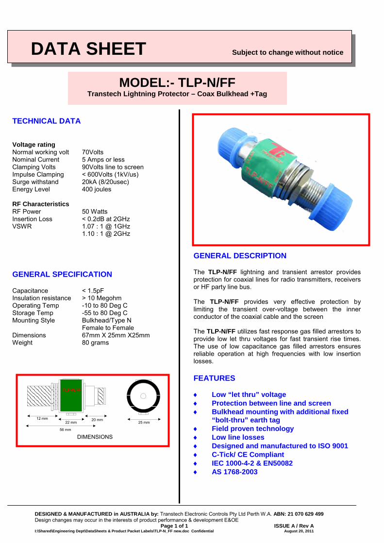
TECHNICAL DATA Voltage rating Normal working volt 70Volts Nominal Current 5 Amps or less Clamping Volts 90Volts line to screen Impulse Clamping < 600Volts (1kV/us) Surge withstand 20kA (8/20usec) Energy Level 400 joules RF Characteristics RF Power 50 Watts Insertion Loss < 0.2dB at 2GHz VSWR 1.07 : 1 @ 1GHz 1.10 : 1 @ 2GHz
GENERAL SPECIFICATION Capacitance < 1.5pF Insulation resistance > 10 Megohm Operating Temp -10 to 80 Deg C Storage Temp -55 to 80 Deg C Mounting Style Bulkhead/Type N Female to Female Dimensions 67mm X 25mm X25mm Weight 80 grams
GENERAL DESCRIPTION The TLP-N/FF lightning and transient arrestor provides protection for coaxial lines for radio transmitters, receivers or HF party line bus. The TLP-N/FF provides very effective protection by limiting the transient over-voltage between the inner conductor of the coaxial cable and the screen The TLP-N/FF utilizes fast response gas filled arrestors to provide low let thru voltages for fast transient rise times. The use of low capacitance gas filled arrestors ensures reliable operation at high frequencies with low insertion losses. FEATURES ♦ Low “let thru” voltage ♦ Protection between line and screen ♦ Bulkhead mounting with additional fixed
“bolt-thru” earth tag ♦ Field proven technology ♦ Low line losses ♦ Designed and manufactured to ISO 9001 ♦ C-Tick/ CE Compliant ♦ IEC 1000-4-2 & EN50082 ♦ AS 1768-2003
MODEL:- TLP-N/FF Transtech Lightning Protector – Coax Bulkhead +Tag
12 mm25 mm
20 mm22 mm
56 mm
DIMENSIONS
TLP-N/FF
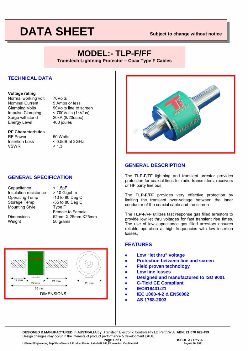
DESIGNED & MANUFACTURED in AUSTRALIA by: Transtech Electronic Controls Pty Ltd Perth W.A. ABN: 21 070 629 499 Design changes may occur in the interests of product performance & development E&OE Page 1 of 1 ISSUE A / Rev A I:\Shared\Engineering Dept\DataSheets & Product Packet Labels\TLP-F_FF new.doc Confidential August 20, 2011
DATA SHEET Subject to change without notice
TECHNICAL DATA Voltage rating Normal working volt 70Volts Nominal Current 5 Amps or less Clamping Volts 90Volts line to screen Impulse Clamping < 700Volts (1kV/us) Surge withstand 20kA (8/20usec) Energy Level 400 joules RF Characteristics RF Power 50 Watts Insertion Loss < 0.5dB at 2GHz VSWR < 1.3
GENERAL SPECIFICATION Capacitance < 1.5pF Insulation resistance > 10 Gigohm Operating Temp -10 to 80 Deg C Storage Temp -55 to 80 Deg C Mounting Style Type F Female to Female Dimensions 52mm X 25mm X25mm Weight 50 grams
GENERAL DESCRIPTION The TLP-F/FF lightning and transient arrestor provides protection for coaxial lines for radio transmitters, receivers or HF party line bus. The TLP-F/FF provides very effective protection by limiting the transient over-voltage between the inner conductor of the coaxial cable and the screen The TLP-F/FF utilizes fast response gas filled arrestors to provide low let thru voltages for fast transient rise times. The use of low capacitance gas filled arrestors ensures reliable operation at high frequencies with low insertion losses. FEATURES ♦ Low “let thru” voltage ♦ Protection between line and screen ♦ Field proven technology ♦ Low line losses ♦ Designed and manufactured to ISO 9001 ♦ C-Tick/ CE Compliant ♦ IEC616431:21 ♦ IEC 1000-4-2 & EN50082 ♦ AS 1768-2003
MODEL:- TLP-F/FF Transtech Lightning Protector – Coax Type F Cables
TLP-F/FF
12 mm25 mm
21 mm22 mm
55 mm
DIMENSIONS
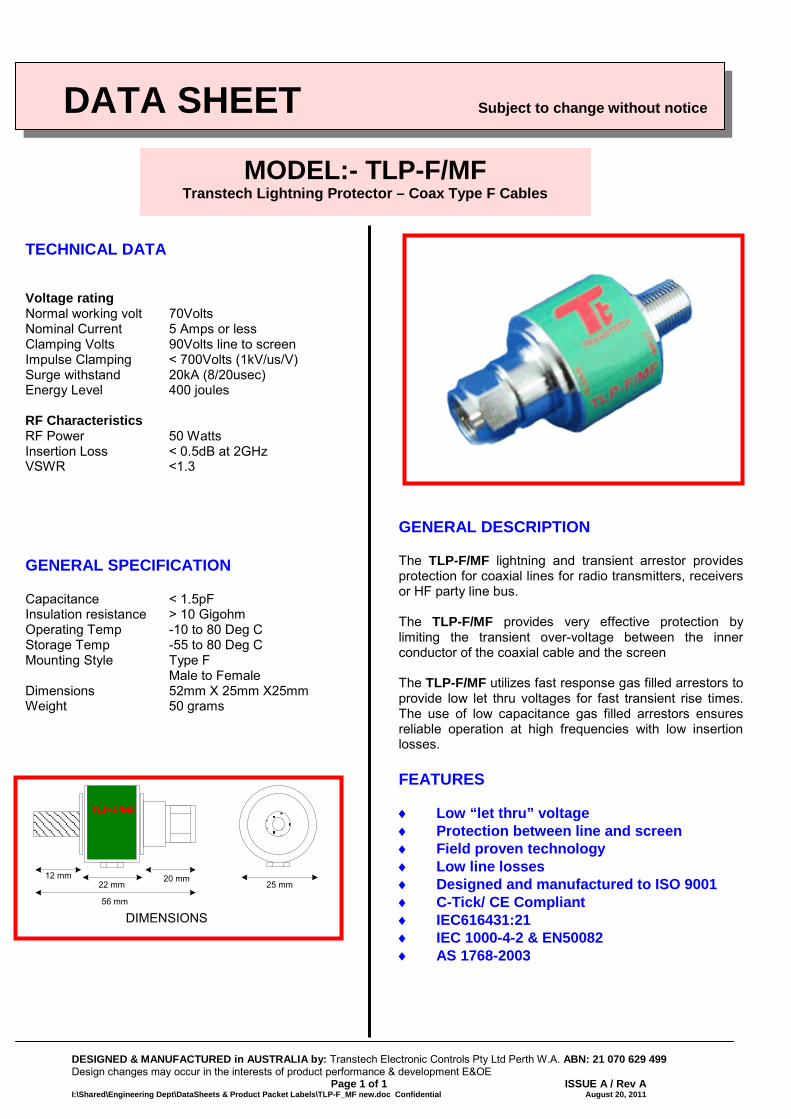
DESIGNED & MANUFACTURED in AUSTRALIA by: Transtech Electronic Controls Pty Ltd Perth W.A. ABN: 21 070 629 499 Design changes may occur in the interests of product performance & development E&OE Page 1 of 1 ISSUE A / Rev A I:\Shared\Engineering Dept\DataSheets & Product Packet Labels\TLP-F_MF new.doc Confidential August 20, 2011
DATA SHEET Subject to change without notice
TECHNICAL DATA Voltage rating Normal working volt 70Volts Nominal Current 5 Amps or less Clamping Volts 90Volts line to screen Impulse Clamping < 700Volts (1kV/us/V) Surge withstand 20kA (8/20usec) Energy Level 400 joules RF Characteristics RF Power 50 Watts Insertion Loss < 0.5dB at 2GHz VSWR <1.3
GENERAL SPECIFICATION Capacitance < 1.5pF Insulation resistance > 10 Gigohm Operating Temp -10 to 80 Deg C Storage Temp -55 to 80 Deg C Mounting Style Type F Male to Female Dimensions 52mm X 25mm X25mm Weight 50 grams
GENERAL DESCRIPTION The TLP-F/MF lightning and transient arrestor provides protection for coaxial lines for radio transmitters, receivers or HF party line bus. The TLP-F/MF provides very effective protection by limiting the transient over-voltage between the inner conductor of the coaxial cable and the screen The TLP-F/MF utilizes fast response gas filled arrestors to provide low let thru voltages for fast transient rise times. The use of low capacitance gas filled arrestors ensures reliable operation at high frequencies with low insertion losses. FEATURES ♦ Low “let thru” voltage ♦ Protection between line and screen ♦ Field proven technology ♦ Low line losses ♦ Designed and manufactured to ISO 9001 ♦ C-Tick/ CE Compliant ♦ IEC616431:21 ♦ IEC 1000-4-2 & EN50082 ♦ AS 1768-2003
MODEL:- TLP-F/MF Transtech Lightning Protector – Coax Type F Cables
TLP-F/MF
12 mm25 mm
20 mm22 mm
56 mm
DIMENSIONS
I:\Shared\Price Lists & data sheets\Transtech\Application Notes\surge protection guide.docx Updated: 15/11/2011/
TransTech Electronic Controls Pty Ltd ABN 21 070 629 499
A GUIDE TO SPECIFYING
ELECTRONIC SURGE PROTECTION DEVICES
Preface: This document is meant as a guide to those involved in specifying, applying and/or approving electronic transient protection devices. It is by no means a definitive paper on the types of transient surge protection available nor in any way proposes to set out a particular manufacturer, type or technique. This guide does not address “structural lightning protection” other than to direct the reader to the Australian Standard AS NZS 1768:2005 and in particular to the proven techniques for effective structural lightning design and installation. Good structural protection and earthing/bonding is an essential part of minimizing possible effects from lightning transients. The most important consideration for any Engineer specifying electronic transient protection is the “let-thru” voltage as this is critical to the proper functioning of the electronic/electrical equipment it is intended to protect following a transient. The critical considerations in specifying electronic transient protectors are:
1. Be compatible with the system it is protecting 2. Survive transients and contain any fault condition arising 3. Have a low “let-thru” voltage for ALL conductor combinations 4. Not fail and leave the installation un-protected 5. Be correctly installed and maintained regularly.
1. Compatibility
The protector should not inhibit the systems normal operation if it operates 2. Survival & housing
Transients from a lightning strike (close proximity) can exceed 200,000 amps, however statistically the average transient is approx 10,000 amps. The IEC Standard uses 10,000 amps as the accepted “norm”, however AS1768 has adopted 70,000 amps therefore any protector at a point of entry should have a rating equal to or exceeding 70,000 amps to meet the current Australian Standard. It is recommended by the leading MOV suppliers that surge protectors incorporating such devices be constructed of metal as a safety precaution Clause 7.9.2 of IEC61643-1:2005 addresses this aspect.
3. Let-thru voltage The magnitude of the transient reaching the electronic/electrical equipment is critical and can cause anything from data-corruption to flash-over and arcing damage. The suitable protector should therefore offer a let-thru voltage less than the maximum voltage rating for the equipment (the current IEC states 2.5kV as the minimum insulation level). Transients occur between all conductors of a system – that is: Ph-N / Ph-E / N-E and in instrumentation and data-line circuits both Common Mode and Differential Mode. Protectors need to offer such levels of protection
4. Indication of failure In-line protectors such as used for 120/240vac sub-circuit, instrumentation and/or data-lines are inherently “self-revealing” upon a major transient as the circuit invariably goes open. In Main Board protection systems it is essential to have an indication to warn of failure or degradation of the protective devices, such indication should be both local visual and a relay output.
5. Installation The performance of transient protectors depends upon correct installation as they are required to manage high frequency waveforms, therefore the length and size of connecting cables must be considered, as a guide refer to AS4070:1992. As a rule of thumb the larger the cross section and the shorter the cable the better, 500mm of 6 sq mm cable is recommended as a minimum.
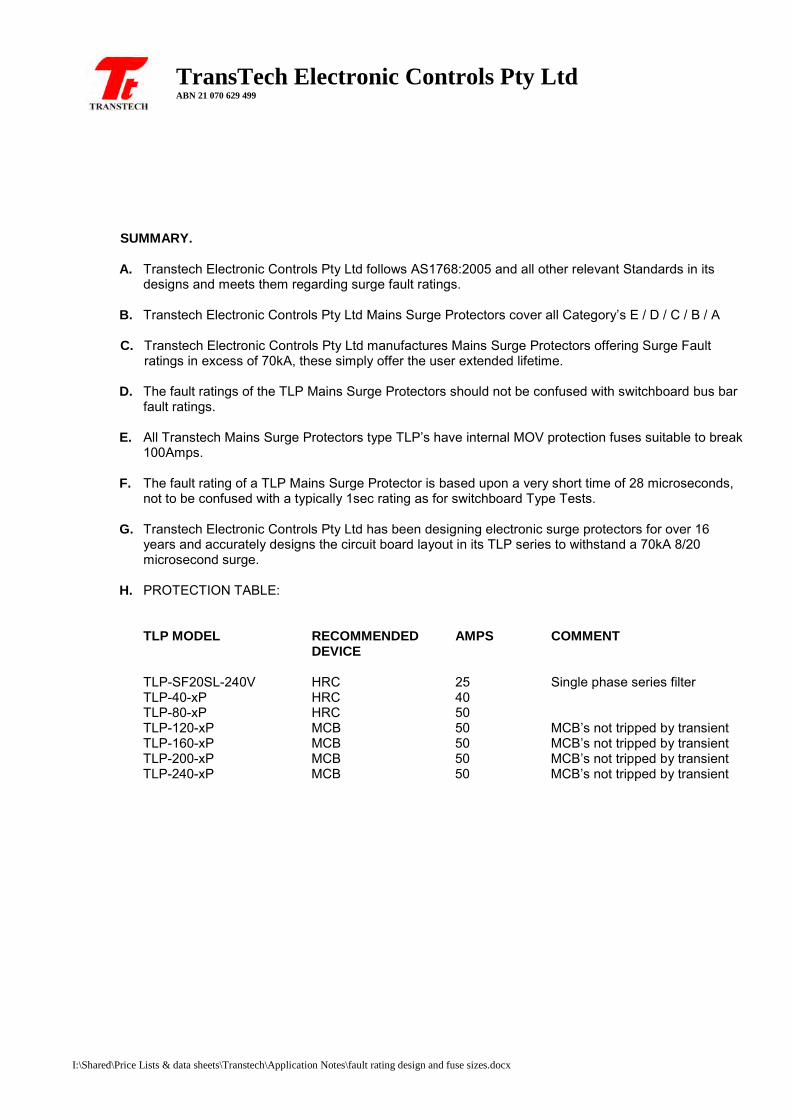
I:\Shared\Price Lists & data sheets\Transtech\Application Notes\fault rating design and fuse sizes.docx
TransTech Electronic Controls Pty Ltd ABN 21 070 629 499
SUMMARY.
A. Transtech Electronic Controls Pty Ltd follows AS1768:2005 and all other relevant Standards in its
designs and meets them regarding surge fault ratings.
B. Transtech Electronic Controls Pty Ltd Mains Surge Protectors cover all Category’s E / D / C / B / A C. Transtech Electronic Controls Pty Ltd manufactures Mains Surge Protectors offering Surge Fault
ratings in excess of 70kA, these simply offer the user extended lifetime.
D. The fault ratings of the TLP Mains Surge Protectors should not be confused with switchboard bus bar fault ratings.
E. All Transtech Mains Surge Protectors type TLP’s have internal MOV protection fuses suitable to break 100Amps.
F. The fault rating of a TLP Mains Surge Protector is based upon a very short time of 28 microseconds, not to be confused with a typically 1sec rating as for switchboard Type Tests.
G. Transtech Electronic Controls Pty Ltd has been designing electronic surge protectors for over 16 years and accurately designs the circuit board layout in its TLP series to withstand a 70kA 8/20 microsecond surge.
H. PROTECTION TABLE:
TLP MODEL RECOMMENDED AMPS COMMENT DEVICE TLP-SF20SL-240V HRC 25 Single phase series filter TLP-40-xP HRC 40 TLP-80-xP HRC 50 TLP-120-xP MCB 50 MCB’s not tripped by transient TLP-160-xP MCB 50 MCB’s not tripped by transient TLP-200-xP MCB 50 MCB’s not tripped by transient TLP-240-xP MCB 50 MCB’s not tripped by transient

Transtech Electronic Controls Pty Ltd ABN 21 070 629 499
Perth - Melbourne Perth Tel: (08) 9302-2044
Melbourne Tel: 0400 848-064 [email protected]
Also in Sydney – Brisbane – Adelaide
TRANSTECH
Transtech Electronic Controls Pty Ltd Australian Agent for:
HAZARDOUS AREA ENCLOSURES
HIGH SPEED SENSORS & TACHOS
ALARM ANNUCIATORS
ENCODERS AND TECHOS
HAZARDOUS AREA FLOW/TEMP/PRESSURE
PROXIMITY SENSORS & PE CELLS