ELEC0047 - Power system dynamics, control and stability ... · Excitation systems and automatic...
16
ELEC0047 - Power system dynamics, control and stability Excitation systems and automatic voltage regulators Thierry Van Cutsem [email protected] www.montefiore.ulg.ac.be/~vct October 2019 1 / 16
Transcript of ELEC0047 - Power system dynamics, control and stability ... · Excitation systems and automatic...

ELEC0047 - Power system dynamics, control and stability
Excitation systems and automatic voltage regulators
Thierry Van [email protected] www.montefiore.ulg.ac.be/~vct
October 2019
1 / 16

Excitation systems and automatic voltage regulators Overview
Overview
2 / 16
Excitation systems and automatic voltage regulators Description of main excitation systems
Description of main excitation systems
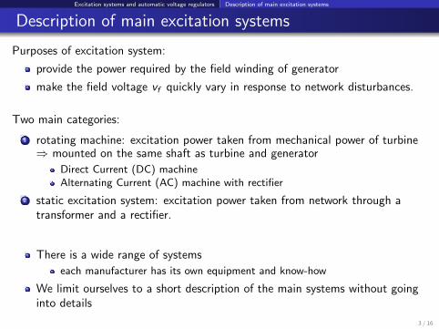
Purposes of excitation system:
provide the power required by the field winding of generator
make the field voltage vf quickly vary in response to network disturbances.
Two main categories:
1 rotating machine: excitation power taken from mechanical power of turbine⇒ mounted on the same shaft as turbine and generator
Direct Current (DC) machineAlternating Current (AC) machine with rectifier
2 static excitation system: excitation power taken from network through atransformer and a rectifier.
There is a wide range of systems
each manufacturer has its own equipment and know-how
We limit ourselves to a short description of the main systems without goinginto details
3 / 16

Excitation systems and automatic voltage regulators Description of main excitation systems
DC generator
Non negligible time constant of exciterthe DC generator can be:
self-excited orseparately excited: requires a “pilot” exciter = separate permanent magnetDC machine
not suited to large units: collector speed below brushes and current too large
has been replaced by power electronics.4 / 16

Excitation systems and automatic voltage regulators Description of main excitation systems
Alternator with non-controlled rectifier
The diode rectifier does not introduce any delay
the firing of the thyristors can be adjusted very rapidly
the exciter still introduces a time constant
the diodes do not allow applying a negative field voltage (if needed duringlarge transients)
5 / 16

Excitation systems and automatic voltage regulators Description of main excitation systems
Alternator with controlled rectifier
The field voltage vf is varied by changing the firing angle of the thyristors,which involves a very short delay
the auxiliary regulator maintains the terminal voltage of the exciter constant
to avoid delays, the exciter alternator operates at full voltage; hence, it isdimensioned to operate permanently at ceiling field voltage
the thyristors allow applying a negative field voltage (if needed during largetransients).
6 / 16

Excitation systems and automatic voltage regulators Description of main excitation systems
Rotating diodes or “brushless” system
Very widespread systemno contact between stator and rotor (no brushes, no slip rings)the rate of change of the field voltage vf is limited by the response time ofthe inverted generatorno access to the field current if of the main generator; the excitation currentof the inverted generator is used as an “image” of if .
7 / 16

Excitation systems and automatic voltage regulators Description of main excitation systems
Potential-source controlled-rectifier or “static” exc. system
A very fast excitation system
the excitation power is drawn from the main generator bus or from anauxiliary bus
in case of short-circuit close to the main generator, the voltage of thetransformer feeding the excitation system drops; this limits the ceiling fieldvoltage.
8 / 16

Excitation systems and automatic voltage regulators Modelling of excitation systems, regulators and limiters
Modelling of excitation systems, regulators and limiters
9 / 16

Excitation systems and automatic voltage regulators Modelling of excitation systems, regulators and limiters
Per unit system
The following base is usually considered :
VfB : the field voltage that produces the nominal voltage VB at the terminalof the open-circuited generator rotating at the nominal speed
IfB : the field current that produces the nominal voltage VB at the terminal ofthe open-circuited generator rotating at the nominal speed.
In steady state, in Volt:vf = Rf if
and in per unit:
vfpu =vfVfB
=Rf ifRf IfB
= ifpu ⇔ Rfpu = 1
This base is different from the one used for the synchronous generator. A changeof base is thus necessary.
10 / 16

Excitation systems and automatic voltage regulators Modelling of excitation systems, regulators and limiters
Simple generic model of automatic voltage regulator and excitation system
Vo : voltage set-point
Zc : compensation impedance; see course ELEC0014
∆Vpss : output of power system stabilizer1 (zero in steady state)
1/(1 + sTm) relates to rectification and filtering of AC voltage; Tm ' 0.05 s
Ga/(1 + sTa) relates to an amplifier; Ta ' 0.05 s. Non-windup limit:
1see lecture on small-disturbance angle stability11 / 16

Excitation systems and automatic voltage regulators Modelling of excitation systems, regulators and limiters
Ge/(1 + sTe) relates to the excitation system;wide variety of values: Te ' from a few 0.01 s to 1 sinternal compensation of the Automatic Voltage Regulator (AVR):
provides desired dynamic response (settling time, overshoot, etc.) usuallyspecified for the generator with stator openeither by lead-lag filter (1 + sT1)/(1 + sT2) in the direct path,or by derivative feedback sKf /(1 + sTf ) in the feedback pathtransient gain reduction : T1 < T2
the OverExcitation Limiter (OEL) acts either through the min gate orthrough the correction signal ∆Voel (see slides 14 and 15)the UnderExcitation Limiter (UEL) acts either through the max gate orthrough the correction signal ∆Vuel (see slide 16)
12 / 16

Excitation systems and automatic voltage regulators Modelling of excitation systems, regulators and limiters
Various items that can be added to the above generic model:
for a diode rectifier: the (rectified) vf voltage decreases when the fieldcurrent if increases
brushless system: internal compensation does not use the (unavailable) vfvoltage
vminf = 0 for the diode rectifier, vmin
f < 0 for the thyristor rectifier
vmaxf sensitive to generator terminal voltage in the static excitation system
magnetic saturation of exciter
etc.
13 / 16

Excitation systems and automatic voltage regulators Modelling of excitation systems, regulators and limiters
Overexcitation limiter acting on summation point of AVR (“non-takeover”):
model initialized with:
y = L1 < 0
switch of block 3 in lowerposition
∆Voel = 0
Bloc 1: u = −1 if if − i limf ≤ d < 0
= 0 if d < if − i limf ≤ 0
= if − i limf if if − i limf > 0
A value i∗f > i limf is tolerated during a time τ such that:
(i∗f − i limf
)τ =
|L1|K1
⇒ τ =|L1|K1
1
i∗f − i limf
inverse-time characteristic. Fixed-time obtained with block 4 instead of 1.14 / 16
Excitation systems and automatic voltage regulators Modelling of excitation systems, regulators and limiters
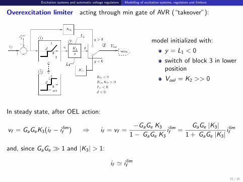
Overexcitation limiter acting through min gate of AVR (“takeover”):
model initialized with:
y = L1 < 0
switch of block 3 in lowerposition
Voel = K2 >> 0
In steady state, after OEL action:
vf = GaGeK3(if − i limf ) ⇒ if = vf =−GaGe K3
1− GaGe K3i limf =
GaGe |K3|1 + GaGe |K3|
i limf
and, since GaGe � 1 and |K3| > 1:
if ' i limf
15 / 16

Excitation systems and automatic voltage regulators Modelling of excitation systems, regulators and limiters
Underexcitation limiter
Aimed at preventing:if from becoming lower than a minimum, orreactive power Q from becoming lower than a minimum (which depends onactive power P).
Example: limiter of second category, acting on summation point of AVR
The integrator output is initially at L1 < 0.If the operating point (P,Q) enters the forbidden zone where :
KP P + KQ Q + Ko < 0
after a delay dictated by L1, the integrator starts acting and eventually forces :
KP P + KQ Q + Ko = 016 / 16