EKI-1500 Series Manual -...
88
User Manual EKI-1500 Series 1/2/4-port RS-232/422/485 Serial Device Servers
Transcript of EKI-1500 Series Manual -...

User Manual
EKI-1500 Series
1/2/4-port RS-232/422/485 Serial Device Servers

Co
Ac
Pro
pyrightThe documentation and the software included with this product are copyrighted 2016by Advantech Co., Ltd. All rights are reserved. Advantech Co., Ltd. reserves the rightto make improvements in the products described in this manual at any time withoutnotice. No part of this manual may be reproduced, copied, translated or transmittedin any form or by any means without the prior written permission of Advantech Co.,Ltd. Information provided in this manual is intended to be accurate and reliable. How-ever, Advantech Co., Ltd. assumes no responsibility for its use, nor for any infringe-ments of the rights of third parties, which may result from its use.
knowledgementsIntel and Pentium are trademarks of Intel Corporation.
Microsoft Windows and MS-DOS are registered trademarks of Microsoft Corp.
All other product names or trademarks are properties of their respective owners.
duct Warranty (5 years)Advantech warrants to you, the original purchaser, that each of its products will befree from defects in materials and workmanship for five years from the date of pur-chase.
This warranty does not apply to any products which have been repaired or altered bypersons other than repair personnel authorized by Advantech, or which have beensubject to misuse, abuse, accident or improper installation. Advantech assumes noliability under the terms of this warranty as a consequence of such events.
Because of Advantech’s high quality-control standards and rigorous testing, most ofour customers never need to use our repair service. If an Advantech product is defec-tive, it will be repaired or replaced at no charge during the warranty period. For out of-warranty repairs, you will be billed according to the cost of replacement materials,service time and freight. Please consult your dealer for more details.
If you think you have a defective product, follow these steps:
1. Collect all the information about the problem encountered. (For example, CPU speed, Advantech products used, other hardware and software used, etc.) Note anything abnormal and list any on screen messages you get when the problem occurs.
2. Call your dealer and describe the problem. Please have your manual, product, and any helpful information readily available.
3. If your product is diagnosed as defective, obtain an RMA (return merchandize authorization) number from your dealer. This allows us to process your return more quickly.
4. Carefully pack the defective product, a fully-completed Repair and Replacement Order Card and a photocopy proof of purchase date (such as your sales receipt) in a shippable container. A product returned without proof of the purchase date is not eligible for warranty service.
5. Write the RMA number visibly on the outside of the package and ship it prepaid to your dealer.
Part No. 2009152102 Edition 3
Printed in Taiwan October 2016
ii EKI-1500 Series User Manual

Declaration of Conformity
CE
This product has passed the CE test for environmental specifications when shieldedcables are used for external wiring. We recommend the use of shielded cables. Thiskind of cable is available from Advantech. Please contact your local supplier forordering information.
This product has passed the CE test for environmental specifications. Test conditionsfor passing included the equipment being operated within an industrial enclosure. Inorder to protect the product from being damaged by ESD (Electrostatic Discharge)and EMI leakage, we strongly recommend the use of CE-compliant industrial enclo-sure products.
FCC Class A
Note: This equipment has been tested and found to comply with the limits for a ClassA digital device, pursuant to part 15 of the FCC Rules. These limits are designed toprovide reasonable protection against harmful interference when the equipment isoperated in a commercial environment. This equipment generates, uses, and canradiate radio frequency energy and, if not installed and used in accordance with theinstruction manual, may cause harmful interference to radio communications. Opera-tion of this equipment in a residential area is likely to cause harmful interference inwhich case the user will be required to correct the interference at his own expense.
Technical Support and Assistance1. Visit the Advantech web site at www.advantech.com/support where you can find
the latest information about the product.2. Contact your distributor, sales representative, or Advantech's customer service
center for technical support if you need additional assistance. Please have the following information ready before you call:– Product name and serial number– Description of your peripheral attachments– Description of your software (operating system, version, application software,
etc.)– A complete description of the problem– The exact wording of any error messages
iii EKI-1500 Series User Manual

Warnings, Cautions and Notes
Document FeedbackTo assist us in making improvements to this manual, we would welcome commentsand constructive criticism. Please send all such - in writing to: [email protected]
Packing ListBefore setting up the system, check that the items listed below are included and ingood condition. If any item does not accord with the table, please contact your dealerimmediately.
1 x EKI-1521 or EKI-1522 or EKI-1524 serial device server 1 x Terminal Block 1 x Document and software CD 2 x Wall/panel mount kit 1 x RS-232 loopback DB9 tester
Warning! Warnings indicate conditions, which if not observed, can cause personal injury!
Caution! Cautions are included to help you avoid damaging hardware or losing data. e.g.
There is a danger of a new battery exploding if it is incorrectly installed. Do not attempt to recharge, force open, or heat the battery. Replace the battery only with the same or equivalent type recommended by the man-ufacturer. Discard used batteries according to the manufacturer's instructions.
Note! Notes provide optional additional information.
EKI-1500 Series User Manual iv

Safety Instructions1. Read these safety instructions carefully.2. Keep this User Manual for later reference.3. Disconnect this equipment from any AC outlet before cleaning. Use a damp
cloth. Do not use liquid or spray detergents for cleaning.4. For plug-in equipment, the power outlet socket must be located near the equip-
ment and must be easily accessible.5. Keep this equipment away from humidity.6. Put this equipment on a reliable surface during installation. Dropping it or letting
it fall may cause damage.7. The openings on the enclosure are for air convection. Protect the equipment
from overheating. DO NOT COVER THE OPENINGS.8. Make sure the voltage of the power source is correct before connecting the
equipment to the power outlet.9. Position the power cord so that people cannot step on it. Do not place anything
over the power cord.10. All cautions and warnings on the equipment should be noted.11. If the equipment is not used for a long time, disconnect it from the power source
to avoid damage by transient overvoltage.12. Never pour any liquid into an opening. This may cause fire or electrical shock.13. Never open the equipment. For safety reasons, the equipment should be
opened only by qualified service personnel.14. If one of the following situations arises, get the equipment checked by service
personnel:15. The power cord or plug is damaged.16. Liquid has penetrated into the equipment.17. The equipment has been exposed to moisture.18. The equipment does not work well, or you cannot get it to work according to the
user's manual.19. The equipment has been dropped and damaged.20. The equipment has obvious signs of breakage.21. CAUTION: DANGER OF EXPLOSION IF BATTERY IS INCORRECTLY
REPLACED. REPLACE ONLY WITH THE SAME OR EQUIVALENT TYPE RECOMMENDED BY THE MANUFACTURER, DISCARD USED BATTERIES ACCORDING TO THE MANUFACTURER'S INSTRUCTIONS.
22. DO NOT LEAVE THIS EQUIPMENT IN AN ENVIRONMENT WHERE THE STORAGE TEMPERATURE MAY GO BELOW -40°C (-40°F) OR ABOVE 75°C (167°F). THIS COULD DAMAGE THE EQUIPMENT. THE EQUIPMENT SHOULD BE IN A CONTROLLED ENVIRONMENT.
23. This is building-in equipment and shall be installed in a suitable enclosure.
Warning! Hot surface. Do not touch.
v EKI-1500 Series User Manual

Safety Precaution - Static ElectricityFollow these simple precautions to protect yourself from harm and the products fromdamage.
To avoid electrical shock, always disconnect the power from your PC chassis before you work on it. Don't touch any components on the CPU card or other cards while the PC is on.
Disconnect power before making any configuration changes. The sudden rush of power as you connect a jumper or install a card may damage sensitive elec-tronic components.
EKI-1500 Series User Manual vi

Contents
Chapter 1 Introduction..........................................11.1 Overview ................................................................................................... 21.2 Device Features ........................................................................................ 2
Chapter 2 Getting Started.....................................32.1 Specifications ............................................................................................ 42.2 Hardware................................................................................................... 6
2.2.1 Front View..................................................................................... 6Figure 2.1 Front View ................................................................ 6Figure 2.2 Front View ................................................................ 7Figure 2.3 Front View ................................................................ 8
2.2.2 Rear View ..................................................................................... 9Figure 2.4 Rear View................................................................. 9Figure 2.5 Rear View............................................................... 10
2.2.3 Top View..................................................................................... 10Figure 2.6 Top View................................................................. 10Figure 2.7 Top View................................................................. 11
2.2.4 LED Indicators ............................................................................ 11Figure 2.8 System LED Panel ................................................. 11
2.2.5 Dimensions ................................................................................. 12Figure 2.9 Dimensions............................................................. 12Figure 2.10 Dimensions............................................................. 13
2.3 Connecting Hardware ............................................................................. 142.3.1 Choosing a Location ................................................................... 14
Figure 2.11 Installing the Mounting Bracket .............................. 14Figure 2.12 Installing the DIN-Rail Mounting Kit........................ 15Figure 2.13 Removing the DIN-Rail........................................... 15Figure 2.14 Installing Wall Mount Plates ................................... 16Figure 2.15 Securing Wall Mounting Screws............................. 17Figure 2.16 Wall Mount Installation ........................................... 17
2.3.2 Serial Connection........................................................................ 18Figure 2.17 DB9 Pin Assignment............................................... 18
2.3.3 Power Connection....................................................................... 18Figure 2.18 Power Wiring for EKI-1500 Series.......................... 19
Chapter 3 Utility Configuration ..........................203.1 Installing the Configuration Utility............................................................ 21
Figure 3.1 InstallShield Wizard 1 of 4 ...................................... 21Figure 3.2 InstallShield Wizard 2 of 4 ...................................... 22Figure 3.3 InstallShield Wizard 3 of 4 ...................................... 22Figure 3.4 InstallShield Wizard 4 of 4 ...................................... 23
3.2 Starting the Configuration Utility.............................................................. 24Figure 3.5 Configuration Utility Overview ................................ 24
3.3 Discovering Your Device Server ............................................................. 253.3.1 Auto Searching ........................................................................... 25
Figure 3.6 Open View of Serial Device Configuration Utility.... 25Figure 3.7 Selecting a Group................................................... 26Figure 3.8 Selecting a Device.................................................. 26Figure 3.9 Viewing Basic Settings ........................................... 26
3.3.2 Network Settings......................................................................... 27Figure 3.10 Utility Overview....................................................... 27
vii EKI-1500 Series User Manual

Figure 3.11 Network Settings Overview .................................... 283.4 Administrator Settings............................................................................. 29
3.4.1 Locate the Serial Device Server ................................................. 29Figure 3.12 Locate the Serial Device Server............................. 29
3.4.2 Securing the Serial Device Server.............................................. 30Figure 3.13 Lock the Serial Device Server ................................ 30Figure 3.14 Enter a Password ................................................... 30Figure 3.15 Reset Device .......................................................... 31Figure 3.16 Unlock the Serial Device Server............................. 31
3.4.3 Restore to Factory Default Settings............................................ 32Figure 3.17 Restore to Factory Default Settings ....................... 32
3.4.4 Resetting the Device................................................................... 33Figure 3.18 Reset Device .......................................................... 33
3.4.5 Add to Favorite ........................................................................... 34Figure 3.19 Add to Favorite ....................................................... 34
3.4.6 Auto Mapping.............................................................................. 343.4.7 Manual Mapping ......................................................................... 343.4.8 Update Firmware ........................................................................ 35
Figure 3.20 Update Firmware.................................................... 35
Chapter 4 Selecting An Operating Mode.......... 364.1 Overview ................................................................................................. 374.2 COM Port Redirector (Virtual COM Port)................................................ 37
Figure 4.1 Virtual COM Mode.................................................. 37Figure 4.2 Configuring Virtual COM Mode .............................. 38
4.2.1 Normal mode .............................................................................. 384.2.2 Round-Robin mode..................................................................... 38
4.3 USDG Data Mode ................................................................................... 394.3.1 USDG TCP Client Mode ............................................................. 39
Figure 4.3 USDG TCP Client Mode......................................... 39Figure 4.4 Peers for Receiving Data ....................................... 39
4.3.2 USDG Data TCP Server mode ................................................... 40Figure 4.5 USDG TCP Server Mode ....................................... 40Figure 4.6 USDG Data Mode .................................................. 40
4.3.3 USDG UDP Server/Client mode ................................................. 404.4 USDG Control Mode ............................................................................... 41
Figure 4.7 USDG Control Mode .............................................. 414.4.1 Hangup Character ...................................................................... 414.4.2 Guard Time................................................................................. 42
4.5 RFC2217 Mode....................................................................................... 42
Chapter 5 Setting up Virtual COM Port............. 435.1 Setting COM Port Redirector .................................................................. 445.2 Virtual COM Port Mapping ...................................................................... 44
5.2.1 Auto Mapping.............................................................................. 44Figure 5.1 Selecting Auto Mapping ......................................... 44Figure 5.2 Selecting Auto Mapping ......................................... 45Figure 5.3 Mapping Selected Ports ......................................... 45Figure 5.4 Viewing VCOM Mapping Results ........................... 45
5.2.2 Manual Mapping ......................................................................... 46Figure 5.5 Selecting Manual Mapping ..................................... 46Figure 5.6 Viewing Manual VCOM Mapping Results .............. 46Figure 5.7 Viewing Manual VCOM Mapping Results .............. 47
5.2.3 Configuration Wizard .................................................................. 47Figure 5.8 Selecting the Configuration Wizard ........................ 47
5.2.4 Confirming Virtual COM Settings................................................ 48Figure 5.9 Serial Port Listing on EKI Device ........................... 48
EKI-1500 Series User Manual viii
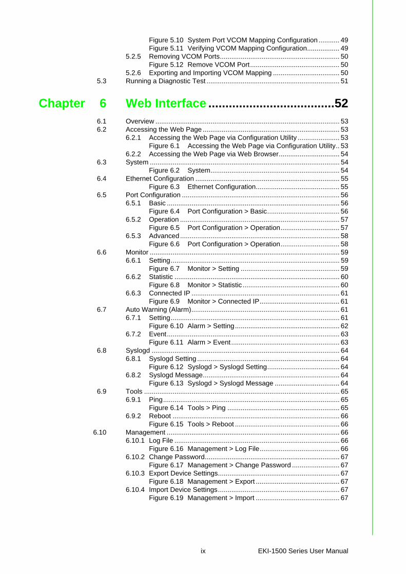
Figure 5.10 System Port VCOM Mapping Configuration ........... 49Figure 5.11 Verifying VCOM Mapping Configuration................. 49
5.2.5 Removing VCOM Ports............................................................... 50Figure 5.12 Remove VCOM Port............................................... 50
5.2.6 Exporting and Importing VCOM Mapping ................................... 505.3 Running a Diagnostic Test ...................................................................... 51
Chapter 6 Web Interface .....................................526.1 Overview ................................................................................................. 536.2 Accessing the Web Page ........................................................................ 53
6.2.1 Accessing the Web Page via Configuration Utility ...................... 53Figure 6.1 Accessing the Web Page via Configuration Utility.. 53
6.2.2 Accessing the Web Page via Web Browser................................ 546.3 System .................................................................................................... 54
Figure 6.2 System.................................................................... 546.4 Ethernet Configuration ............................................................................ 55
Figure 6.3 Ethernet Configuration............................................ 556.5 Port Configuration ................................................................................... 56
6.5.1 Basic ........................................................................................... 56Figure 6.4 Port Configuration > Basic...................................... 56
6.5.2 Operation .................................................................................... 57Figure 6.5 Port Configuration > Operation............................... 57
6.5.3 Advanced .................................................................................... 58Figure 6.6 Port Configuration > Operation............................... 58
6.6 Monitor .................................................................................................... 596.6.1 Setting......................................................................................... 59
Figure 6.7 Monitor > Setting .................................................... 596.6.2 Statistic ....................................................................................... 60
Figure 6.8 Monitor > Statistic ................................................... 606.6.3 Connected IP .............................................................................. 61
Figure 6.9 Monitor > Connected IP.......................................... 616.7 Auto Warning (Alarm).............................................................................. 61
6.7.1 Setting......................................................................................... 61Figure 6.10 Alarm > Setting....................................................... 62
6.7.2 Event........................................................................................... 63Figure 6.11 Alarm > Event......................................................... 63
6.8 Syslogd ................................................................................................... 646.8.1 Syslogd Setting ........................................................................... 64
Figure 6.12 Syslogd > Syslogd Setting...................................... 646.8.2 Syslogd Message........................................................................ 64
Figure 6.13 Syslogd > Syslogd Message .................................. 646.9 Tools ....................................................................................................... 65
6.9.1 Ping............................................................................................. 65Figure 6.14 Tools > Ping ........................................................... 65
6.9.2 Reboot ........................................................................................ 66Figure 6.15 Tools > Reboot ....................................................... 66
6.10 Management ........................................................................................... 666.10.1 Log File ....................................................................................... 66
Figure 6.16 Management > Log File.......................................... 666.10.2 Change Password....................................................................... 67
Figure 6.17 Management > Change Password ......................... 676.10.3 Export Device Settings................................................................ 67
Figure 6.18 Management > Export ............................................ 676.10.4 Import Device Settings................................................................ 67
Figure 6.19 Management > Import ............................................ 67
ix EKI-1500 Series User Manual

Chapter 7 Telnet/Serial Console Configuration .................................... 68
7.1 Overview ................................................................................................. 697.2 Telnet Console........................................................................................ 69
7.2.1 Create a new connection ............................................................ 69Figure 7.1 Creating a Telnet Connection................................. 69
7.2.2 Input the IP address.................................................................... 70Figure 7.2 Creating a Telnet Connection................................. 70
7.2.3 Connection Success ................................................................... 70Figure 7.3 Telnet Connection Console .................................... 70
7.3 Command List......................................................................................... 717.3.1 system ........................................................................................ 717.3.2 port.............................................................................................. 717.3.3 portadv........................................................................................ 727.3.4 mvcom ........................................................................................ 727.3.5 mctrl ............................................................................................ 737.3.6 mdata.......................................................................................... 737.3.7 net............................................................................................... 737.3.8 password .................................................................................... 747.3.9 alarm........................................................................................... 747.3.10 monitor........................................................................................ 747.3.11 time............................................................................................. 747.3.12 service ........................................................................................ 757.3.13 mrfc2217..................................................................................... 757.3.14 apply ........................................................................................... 757.3.15 exit .............................................................................................. 757.3.16 help ............................................................................................. 757.3.17 reboot.......................................................................................... 75
Chapter A TCP and UDP Port Numbers ............ 76A.1 List of Known TCP and UDP Port Numbers ........................................... 77
EKI-1500 Series User Manual x

Chapter 1
1Introduction
1.1 OverviewThe EKI-1500 Series are network-based serial device servers that connect RS-232/422/485 serial devices, such as PLC, meters, sensors, and barcode readers, directlyto a TCP/IP network.
Once connected through a EKI-1500 Series serial server, devices are able to sendand receive data through a network. This extends the traditional COM ports of a PC,with access over a TCP/IP network. Through networking, you can control and moni-tor remote serial devices over either a LAN or WAN. Since the EKI-1500 Series isconnected through a TCP/IP network, you may need to know some basic facts aboutnetworking in order to connect the server correctly.
The EKI-1500 Series features two independent Ethernet ports and MAC addressesto provide a redundant network mechanism to avoid data loss. The EKI-1500 Seriesprovides various operations: COM port redirection mode (Virtual COM Port mode),TCP Server/ Client mode, UDP mode, Control mode and RFC2217 mode. Detaileddescriptions of each operation are provided in a later chapter.
1.2 Device Features Provides 2 x 10/100 Mbps Ethernet ports for LAN redundancy Provides COM port redirection (Virtual COM), TCP and UDP operation modes Supports up to 921.6 kbps, and any baud rate setting Allows a max. of 5 hosts to access one serial port Allows a max. of 16 hosts to be accessed as TCP client mode Built-in 15 KV ESD protection for all serial signals Provides rich configuration access, including: Windows utility, Telnet console,
and Web Browser Supports 32-bit/64-bit Windows 2000/XP/Vista/7/8/8.1/10, Windows Server
2003/2008/2012, and Linux Automatic RS-485 data flow control Supports surge protection for D.C. power ports with line to line 2 KV, and line to
earth 4 KV; for signal ports with 4 KV. Supports a wide operating temperature (I models only) Supports isolation and wide operating temperature (CI models only)
EKI-1500 Series User Manual 2

Chapter 2
2Getting Started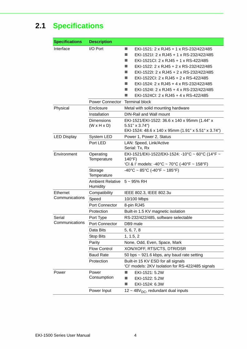
2.1 Specifications
Specifications Description
Interface I/O Port EKI-1521: 2 x RJ45 + 1 x RS-232/422/485
EKI-1521I: 2 x RJ45 + 1 x RS-232/422/485
EKI-1521CI: 2 x RJ45 + 1 x RS-422/485
EKI-1522: 2 x RJ45 + 2 x RS-232/422/485
EKI-1522I: 2 x RJ45 + 2 x RS-232/422/485
EKI-1522CI: 2 x RJ45 + 2 x RS-422/485
EKI-1524: 2 x RJ45 + 4 x RS-232/422/485
EKI-1524I: 2 x RJ45 + 4 x RS-232/422/485
EKI-1524CI: 2 x RJ45 + 4 x RS-422/485
Power Connector Terminal block
Physical Enclosure Metal with solid mounting hardware
Installation DIN-Rail and Wall mount
Dimensions (W x H x D)
EKI-1521/EKI-1522: 36.6 x 140 x 95mm (1.44" x 5.51" x 3.74")EKI-1524: 48.6 x 140 x 95mm (1.91" x 5.51" x 3.74")
LED Display System LED Power 1, Power 2, Status
Port LED LAN: Speed, Link/ActiveSerial: Tx, Rx
Environment Operating Temperature
EKI-1521/EKI-1522/EKI-1524: -10°C ~ 60°C (14°F ~ 140°F)‘CI & I’ models: -40°C ~ 70°C (-40°F ~ 158°F)
Storage Temperature
-40°C ~ 85°C (-40°F ~ 185°F)
Ambient Relative Humidity
5 ~ 95% RH
Ethernet Communications
Compatibility IEEE 802.3, IEEE 802.3u
Speed 10/100 Mbps
Port Connector 8-pin RJ45
Protection Built-in 1.5 KV magnetic isolation
Serial Communications
Port Type RS-232/422/485, software selectable
Port Connector DB9 male
Data Bits 5, 6, 7, 8
Stop Bits 1, 1.5, 2
Parity None, Odd, Even, Space, Mark
Flow Control XON/XOFF, RTS/CTS, DTR/DSR
Baud Rate 50 bps ~ 921.6 kbps, any baud rate setting
Protection Built-in 15 KV ESD for all signals'CI' models: 2KV Isolation for RS-422/485 signals
Power Power Consumption
EKI-1521: 5.2W
EKI-1522: 5.2W
EKI-1524: 6.3W
Power Input 12 ~ 48VDC, redundant dual inputs
EKI-1500 Series User Manual 4

Software Driver Support 32-bit/64-bit Windows XP/Vista/7/8/8.1/10, Windows Server 2003/2008/2008 R2/2012/2012 R2, and Linux
Utility Advantech EKI Device Configuration Utility
Operation Modes COM port redirection mode (Virtual COM)
TCP/UDP server (polling) mode
TCP/UDP client (event handling) mode
Pair connection (peer to peer) mode
Configuration Windows utility, Telnet console, Web Browser
Management SNMP MIB-II
Regulatory Approvals
EMC CE, FCC Part 15 Subpart B (Class A)
Safety UL (UL60950-1), Class 1, Div II, ATEX
Specifications Description
5 EKI-1500 Series User Manual

2.2 Hardware
2.2.1 Front ViewThe following view shows the EKI-1521.
Figure 2.1 Front View
No. Item Description
1 System LED panel See “LED Indicators” on page 11 for further details.
2 ETH port RJ45 ports x 2
3 Serial port DB9 pinout, supports RS-232/422/485
1
1
2
Default
LAN
TxRx
P1 P2 Status
Serial ports
EKI-1521
1
2
3
EKI-1500 Series User Manual 6
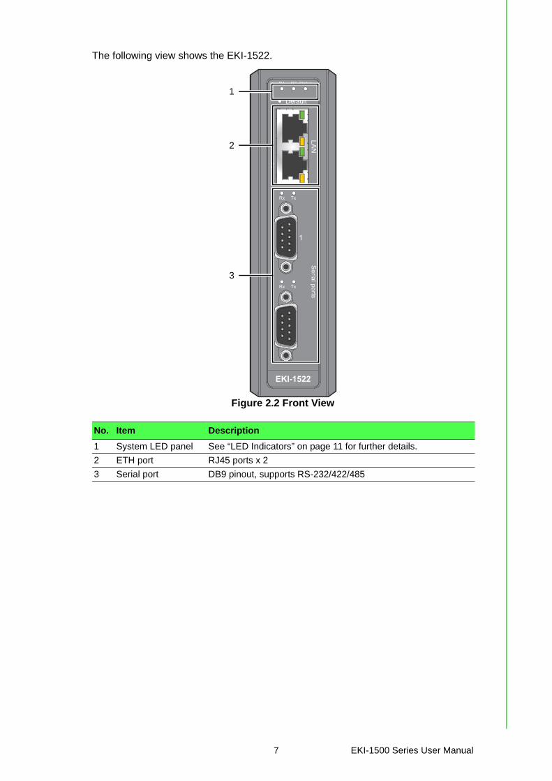
The following view shows the EKI-1522.
Figure 2.2 Front View
No. Item Description
1 System LED panel See “LED Indicators” on page 11 for further details.
2 ETH port RJ45 ports x 2
3 Serial port DB9 pinout, supports RS-232/422/485
1
1
2
Default
LAN
TxRx
TxRx
P1 P2 Status
Serial ports
EKI-1522
1
2
3
7 EKI-1500 Series User Manual
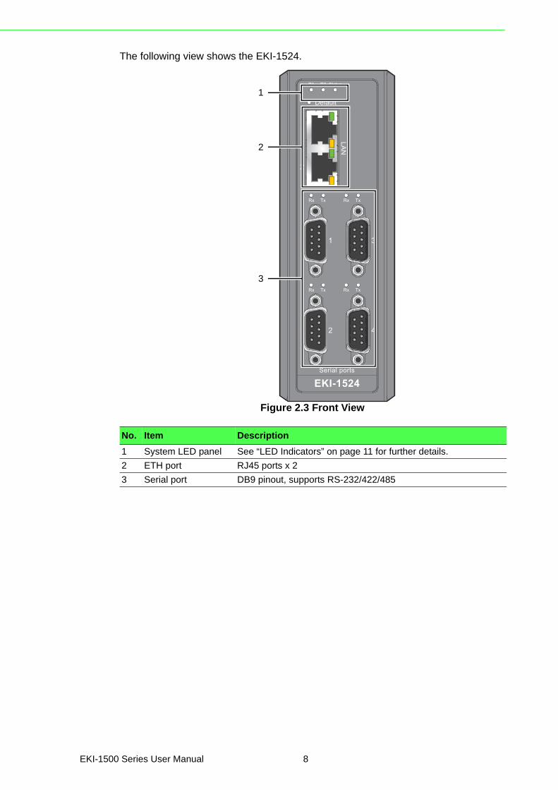
The following view shows the EKI-1524.
Figure 2.3 Front View
No. Item Description
1 System LED panel See “LED Indicators” on page 11 for further details.
2 ETH port RJ45 ports x 2
3 Serial port DB9 pinout, supports RS-232/422/485
EKI-1524
1
1
2
3
4
2
Default
LAN
TxRx
TxRx
TxRx
TxRx
P1 P2 Status
Serial ports
1
2
3
EKI-1500 Series User Manual 8
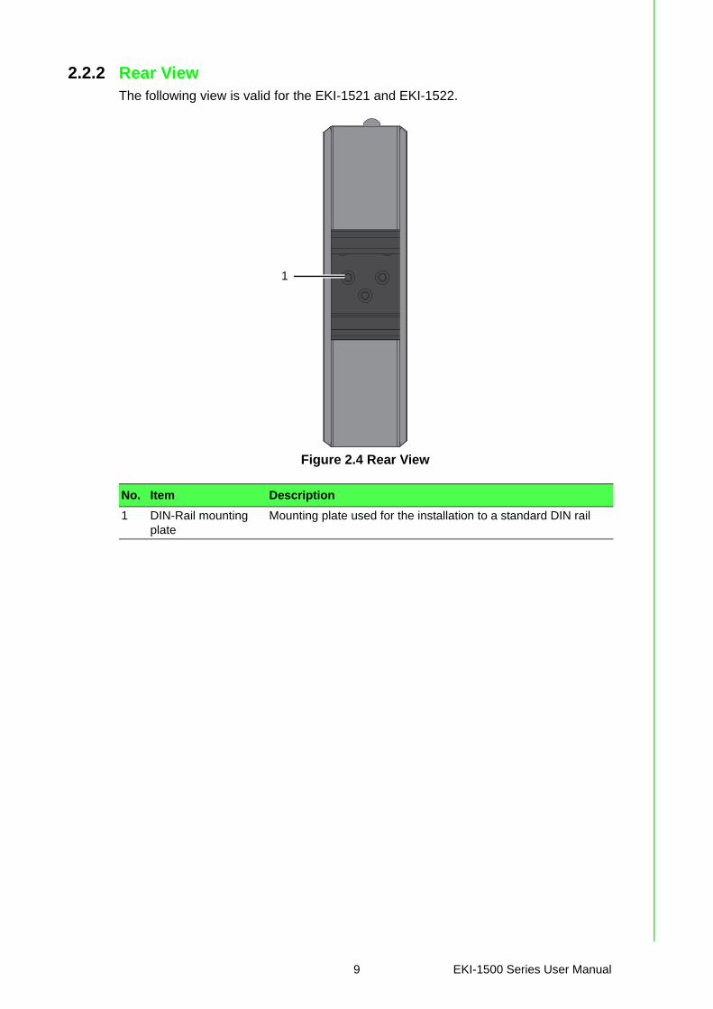
2.2.2 Rear ViewThe following view is valid for the EKI-1521 and EKI-1522.
Figure 2.4 Rear View
No. Item Description
1 DIN-Rail mounting plate
Mounting plate used for the installation to a standard DIN rail
1
9 EKI-1500 Series User Manual
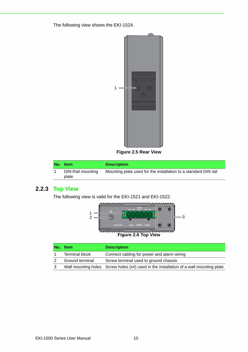
The following view shows the EKI-1524.
Figure 2.5 Rear View
2.2.3 Top ViewThe following view is valid for the EKI-1521 and EKI-1522.
Figure 2.6 Top View
No. Item Description
1 DIN-Rail mounting plate
Mounting plate used for the installation to a standard DIN rail
1
No. Item Description
1 Terminal block Connect cabling for power and alarm wiring
2 Ground terminal Screw terminal used to ground chassis
3 Wall mounting holes Screw holes (x4) used in the installation of a wall mounting plate
PWR2
P-Fail
DC12-48V PWR1
V2- V2+V1- V1+
1A@24V
132
EKI-1500 Series User Manual 10
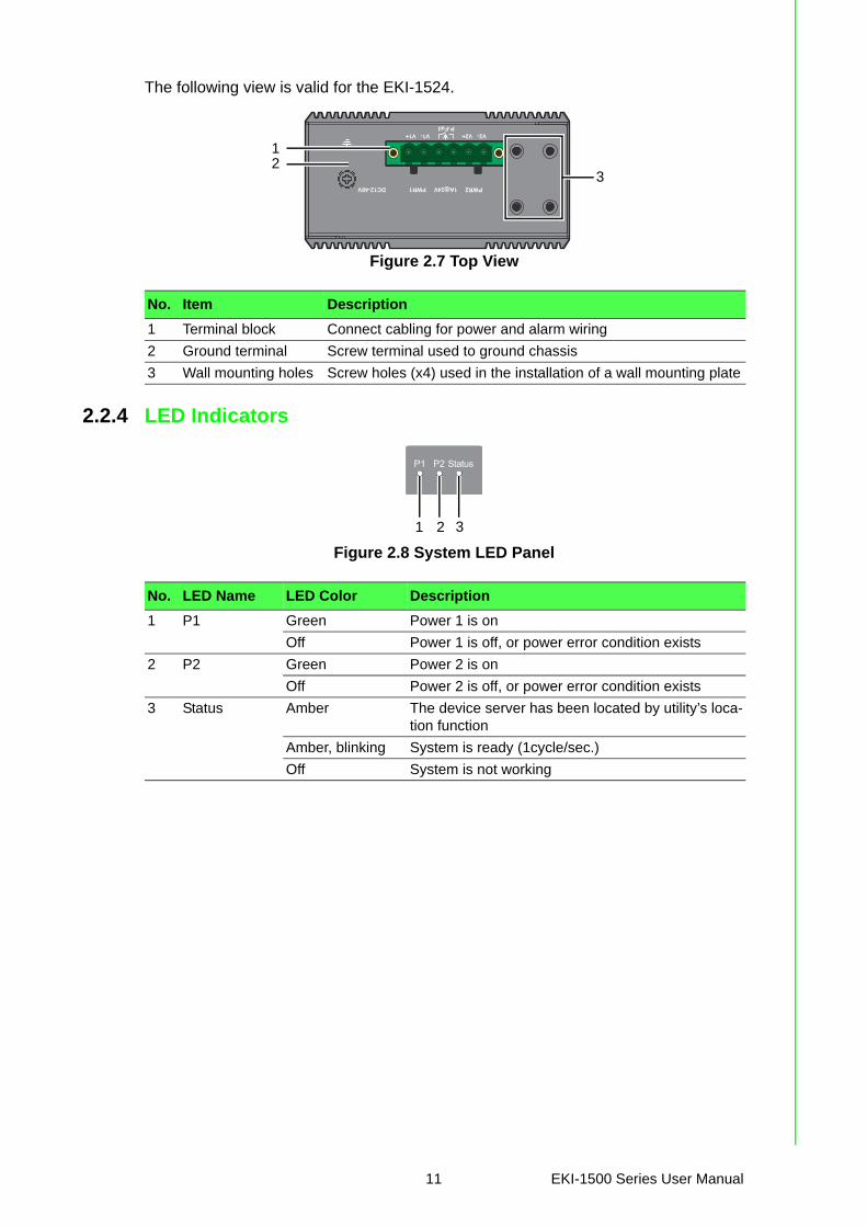
The following view is valid for the EKI-1524.
Figure 2.7 Top View
2.2.4 LED Indicators
Figure 2.8 System LED Panel
No. Item Description
1 Terminal block Connect cabling for power and alarm wiring
2 Ground terminal Screw terminal used to ground chassis
3 Wall mounting holes Screw holes (x4) used in the installation of a wall mounting plate
PWR2
P-Fail
DC12-48V PWR1
V2- V2+V1- V1+
1A@24V
1
32
No. LED Name LED Color Description
1 P1 Green Power 1 is on
Off Power 1 is off, or power error condition exists
2 P2 Green Power 2 is on
Off Power 2 is off, or power error condition exists
3 Status Amber The device server has been located by utility’s loca-tion function
Amber, blinking System is ready (1cycle/sec.)
Off System is not working
P1 P2 Status
1 2 3
11 EKI-1500 Series User Manual
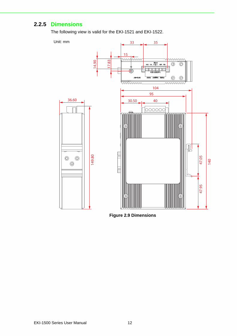
2.2.5 DimensionsThe following view is valid for the EKI-1521 and EKI-1522.
Figure 2.9 Dimensions
36.60
149.80
10495
30.50 40
140
47.05
47.95
33
15
35
14.90
17.83
Unit: mm
EKI-1500 Series User Manual 12
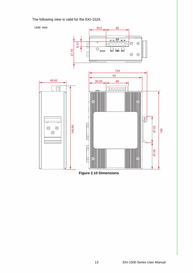
The following view is valid for the EKI-1524.
Figure 2.10 Dimensions
48.60
149.80
10495
30.50 40
140
47.05
47.95
30.5 40
37.70
8.32
Unit: mm
13 EKI-1500 Series User Manual
2.3 Connecting Hardware
2.3.1 Choosing a Location
2.3.1.1 DIN Rail MountingThe DIN rail mount option is the quickest installation option. Additionally, it optimizesthe use of rail space.
The metal DIN rail kit is secured to the rear of the serial device server. The devicecan be mounted onto a standard 35mm (1.37”) x 75mm (3”) height DIN rail. Thedevices can be mounted vertically or horizontally. Refer to the following guidelines forfurther information.
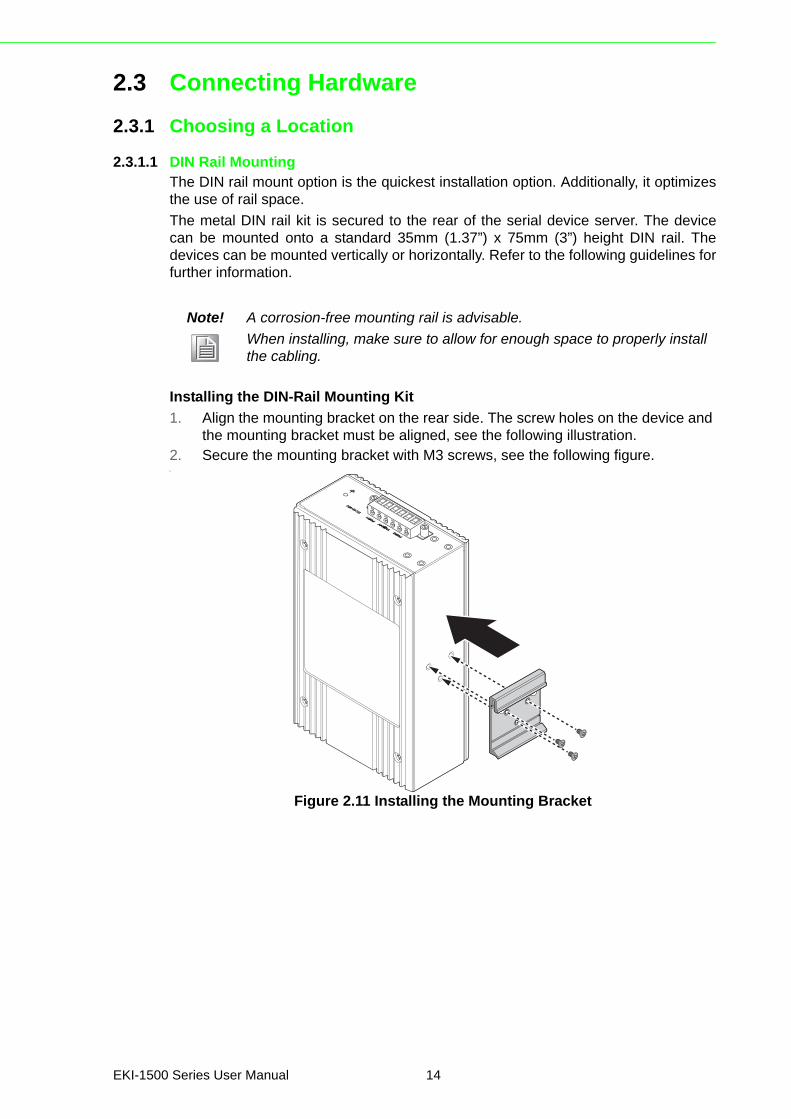
Installing the DIN-Rail Mounting Kit
1. Align the mounting bracket on the rear side. The screw holes on the device and the mounting bracket must be aligned, see the following illustration.
2. Secure the mounting bracket with M3 screws, see the following figure.\
Figure 2.11 Installing the Mounting Bracket
Note! A corrosion-free mounting rail is advisable.
When installing, make sure to allow for enough space to properly install the cabling.
EKI-1500 Series User Manual 14
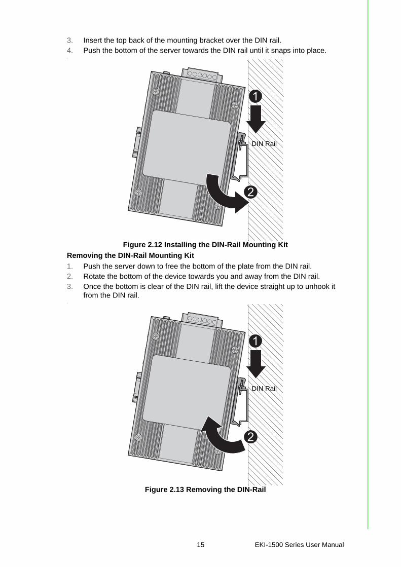
3. Insert the top back of the mounting bracket over the DIN rail.4. Push the bottom of the server towards the DIN rail until it snaps into place.\
Figure 2.12 Installing the DIN-Rail Mounting Kit
Removing the DIN-Rail Mounting Kit
1. Push the server down to free the bottom of the plate from the DIN rail.2. Rotate the bottom of the device towards you and away from the DIN rail.3. Once the bottom is clear of the DIN rail, lift the device straight up to unhook it
from the DIN rail.\
Figure 2.13 Removing the DIN-Rail
2
1
DIN Rail
2
1
DIN Rail
15 EKI-1500 Series User Manual
2.3.1.2 Wall-MountingThe wall mounting option provides better shock and vibration resistance than the DINrail vertical mount.
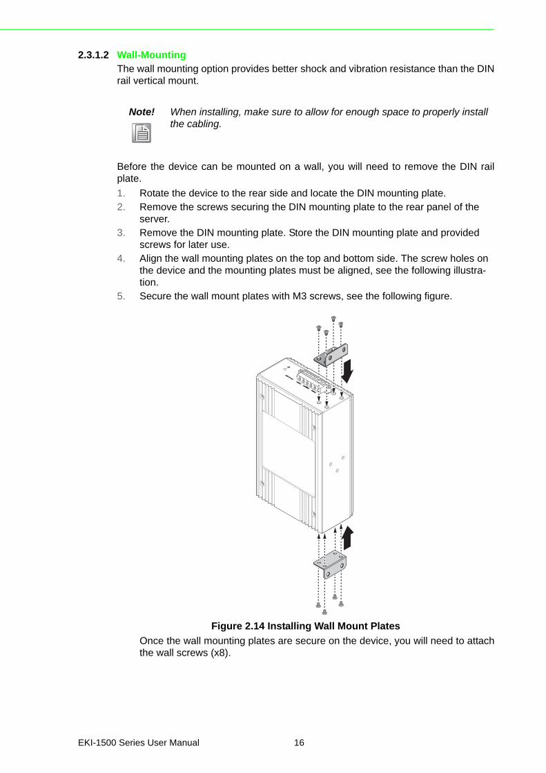
Before the device can be mounted on a wall, you will need to remove the DIN railplate.
1. Rotate the device to the rear side and locate the DIN mounting plate.2. Remove the screws securing the DIN mounting plate to the rear panel of the
server.3. Remove the DIN mounting plate. Store the DIN mounting plate and provided
screws for later use.4. Align the wall mounting plates on the top and bottom side. The screw holes on
the device and the mounting plates must be aligned, see the following illustra-tion.
5. Secure the wall mount plates with M3 screws, see the following figure.
Figure 2.14 Installing Wall Mount Plates
Once the wall mounting plates are secure on the device, you will need to attachthe wall screws (x8).
Note! When installing, make sure to allow for enough space to properly install the cabling.
EKI-1500 Series User Manual 16
6. Locate the installation site and place the server against the wall, making sure it is the final installation location.
7. Use the wall mount plates as a guide to mark the locations of the screw holes.8. Drill four holes over the four marked locations on the wall, keeping in mind that
the holes must accommodate wall sinks in addition to the screws.9. Insert the wall sinks into the walls.10. Insert the screws into the wall sinks.
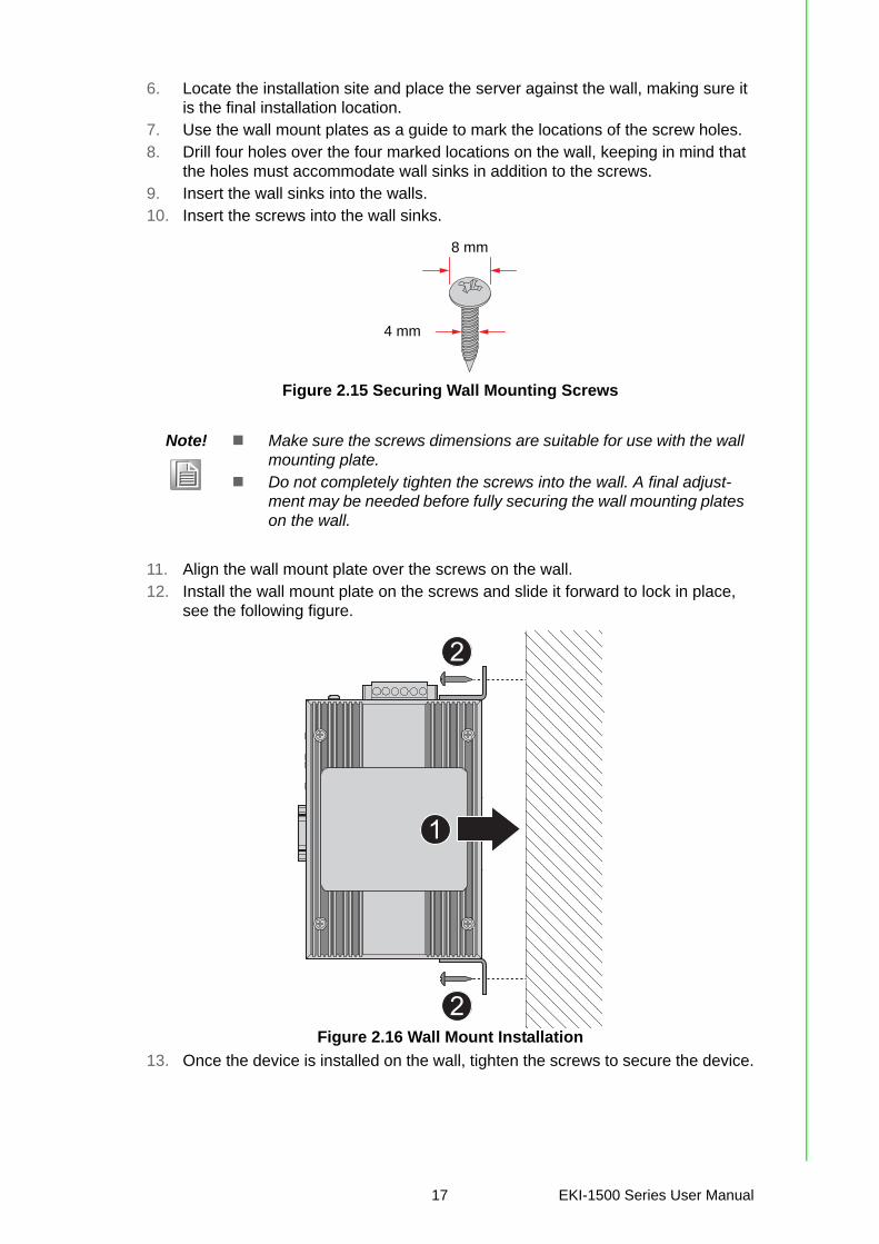
Figure 2.15 Securing Wall Mounting Screws
11. Align the wall mount plate over the screws on the wall.12. Install the wall mount plate on the screws and slide it forward to lock in place,
see the following figure.
Figure 2.16 Wall Mount Installation
13. Once the device is installed on the wall, tighten the screws to secure the device.
Note! Make sure the screws dimensions are suitable for use with the wall mounting plate.
Do not completely tighten the screws into the wall. A final adjust-ment may be needed before fully securing the wall mounting plates on the wall.
8 mm
4 mm
2
2
1
17 EKI-1500 Series User Manual

2.3.2 Serial ConnectionEKI-1500 Series provides up to four ports DB9 (male) connectors. RS-232/422/485pin assignments as below:
Figure 2.17 DB9 Pin Assignment
2.3.3 Power Connection
2.3.3.1 Overview
The EKI-1500 Series supports dual 12 to 48 VDC power inputs and power-fail relayoutput.
Pin 1 2 3 4 5 6 7 8 9
RS-232 DCD RX TX DTR GND DSR RTS CTS RI
RS-422 TX- TX+ GND RX+ RX-
RS-485 DATA- DATA+ GND
1
96
5
Warning! Power down and disconnect the power cord before servicing or wiring the serial device server.
Caution! Do not disconnect modules or cabling unless the power is first switched off.
The device only supports the voltage outlined in the type plate. Do not use any other power components except those specifically designated for the serial device server.
Caution! Disconnect the power cord before installation or cable wiring.
EKI-1500 Series User Manual 18
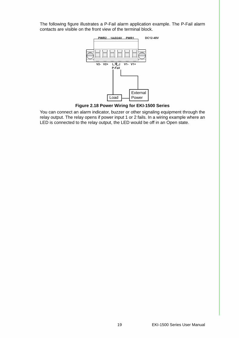
The following figure illustrates a P-Fail alarm application example. The P-Fail alarmcontacts are visible on the front view of the terminal block.
Figure 2.18 Power Wiring for EKI-1500 Series
You can connect an alarm indicator, buzzer or other signaling equipment through therelay output. The relay opens if power input 1 or 2 fails. In a wiring example where anLED is connected to the relay output, the LED would be off in an Open state.
PWR2
P-Fail
DC12-48VPWR1
V2- V2+ V1- V1+
1A@24V
LoadExternal Power
19 EKI-1500 Series User Manual

Chapter 3
3Utility Configuration
3.1 Installing the Configuration Utility
1. Insert the Advantech EKI Device Configuration Utility CD-ROM into the CD-ROM drive (whereas E:\ is the drive name of your CD-ROM) on the host PC.
2. Use Windows explorer or the Windows Run command to execute the setup pro-gram, the path for the setup program on the CD-ROM is as follows:E:\EKI_Device_Configuration_Utility_v2.01.exe
3. If there is an existing COM port mapping utility on the host PC, remove it at this time. A system reboot may be necessary before continuing the installation.
4. Once the InstallShield Wizard screen displays, click Next to proceed with the installation.
Figure 3.1 InstallShield Wizard 1 of 4
Note! Microsoft.NET Framework version 2.0 or greater is required for this application.
21 EKI-1500 Series User Manual
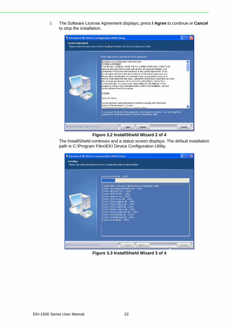
5. The Software License Agreement displays, press I Agree to continue or Cancel to stop the installation.
Figure 3.2 InstallShield Wizard 2 of 4
The InstallShield continues and a status screen displays. The default installationpath is C:\Program Files\EKI Device Configuration Utility.
Figure 3.3 InstallShield Wizard 3 of 4
EKI-1500 Series User Manual 22
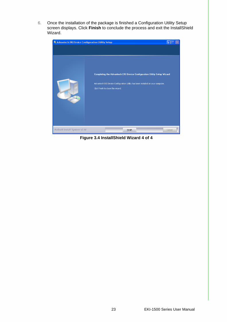
6. Once the installation of the package is finished a Configuration Utility Setup screen displays. Click Finish to conclude the process and exit the InstallShield Wizard.
Figure 3.4 InstallShield Wizard 4 of 4
23 EKI-1500 Series User Manual
3.2 Starting the Configuration UtilityAdvantech EKI series serial device servers provide an easy-to-use utility to configureyour serial device server through an Ethernet connection. For secure administration,it can also restrict the access rights for configuration to only one host PC. With thissecure function enabled, other PCs will not have permission for configuration. Afterthe installation program on the Advantech IEDG Series Driver Utility CD-ROM is fin-ished, the serial device servers are ready for use and configuration.
Advantech Serial Device Server Configuration Utility is an excellent device servermanagement tool. You can connect and configure the local and remote Advantechserial device servers easily. The utility provides access to the following functions:
Configure the network settings (you can set the IP address, Gateway address, and Subnet mask)
View and set the serial port parameters (configure operating mode, baud rate, serial port settings and operating mode settings)
Perform diagnostic tests (virtual COM port testing, port status list) Perform administrative functions (export and import the serial device server set-
ting, manage access IP, a descriptive name, upgrade firmware)You can open the Configuration Utility from the Windows Start Menu by clicking Start> All Programs > EKI Device Configuration Utility > EKI Device ConfigurationUtility. The Configuration Utility displays as shown in the following figure.
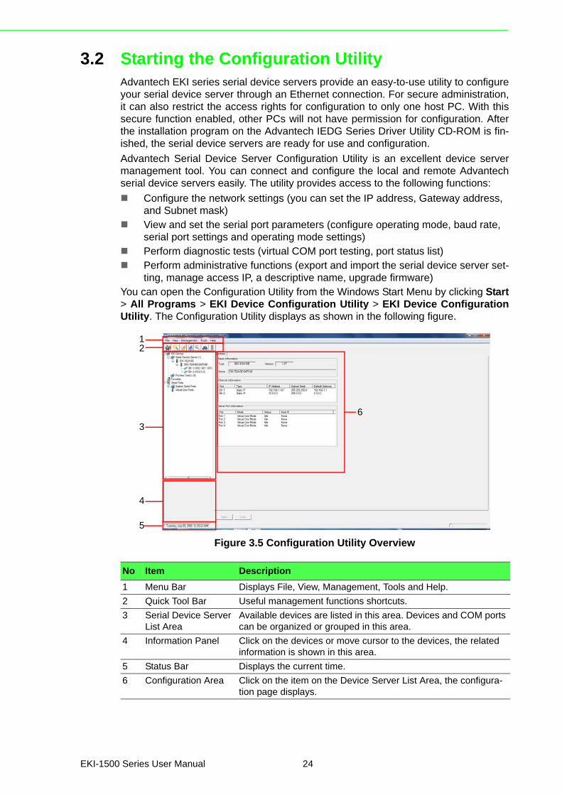
Figure 3.5 Configuration Utility Overview
No Item Description
1 Menu Bar Displays File, View, Management, Tools and Help.
2 Quick Tool Bar Useful management functions shortcuts.
3 Serial Device Server List Area
Available devices are listed in this area. Devices and COM ports can be organized or grouped in this area.
4 Information Panel Click on the devices or move cursor to the devices, the related information is shown in this area.
5 Status Bar Displays the current time.
6 Configuration Area Click on the item on the Device Server List Area, the configura-tion page displays.
5
4
3
2
6
1
EKI-1500 Series User Manual 24

3.3 Discovering Your Device Server
3.3.1 Auto SearchingAdvantech Serial Device Server Configuration Utility will automatically search all theEKI-1500 Series device servers on the network and show them on the Serial DeviceServer List Area of the utility. The utility provides an auto-search function to showyour device (s) by simply executing the configuration utility program from the StartMenu.
From here all device on the same network domain will be searched and displayed onDevice Server List Area. You can click on the device name to show the features ofthe specific device.
Click on the “+” before the model name, and the utility will expand the tree structureto show the individual device name. Click on the “-” before the model name, and theutility will collapse the tree structure.
Figure 3.6 Open View of Serial Device Configuration Utility
In the previous figure, the EKI serial device server is listed as EKI-1524-BE-04FFAB.
Select the device in this sub-tree. The first tab on the Configuration Area shows thesummary of “Basic Information” included device type, version, and name, “Ethernet
Note! When you run the configuration utility for the first time, the default device name is obtained from the serial device’s MAC identification number. The name can be altered through the configuration utility.
25 EKI-1500 Series User Manual
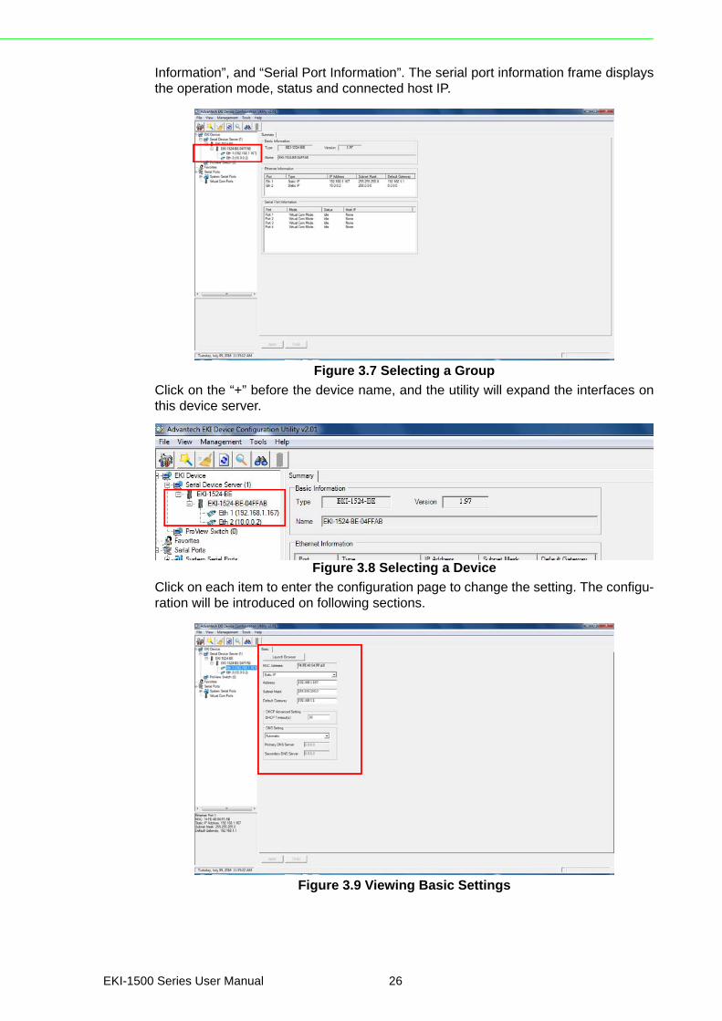
Information”, and “Serial Port Information”. The serial port information frame displaysthe operation mode, status and connected host IP.
Figure 3.7 Selecting a Group
Click on the “+” before the device name, and the utility will expand the interfaces onthis device server.
Figure 3.8 Selecting a Device
Click on each item to enter the configuration page to change the setting. The configu-ration will be introduced on following sections.
Figure 3.9 Viewing Basic Settings
EKI-1500 Series User Manual 26

3.3.2 Network SettingsPrior to setting up the server’s IP address determine the IP address mode.
There are four mode types available:
Static IP: mode to assign a specific assigned address DHCP / AutoIP: mode to automatically assign IP addresses through a DHCP
server BOOTP / AutoIP: mode to automatically assign an IP address through the con-
figuration server DHCP/BOOTP/AutoIP: mode to automatically assign an IP address using a
Bootstrap Protocol or DHCP server.The server is set with the following default IP configuration:
10.0.0.1 (Eth1) 10.0.0.2 (Eth2)The EKI series includes a software utility option, which you can install on your sys-tem, for configuration through computer-based software. The EKI series also
includes a web interface option for configuration through a standard web browser.
Figure 3.10 Utility Overview
27 EKI-1500 Series User Manual
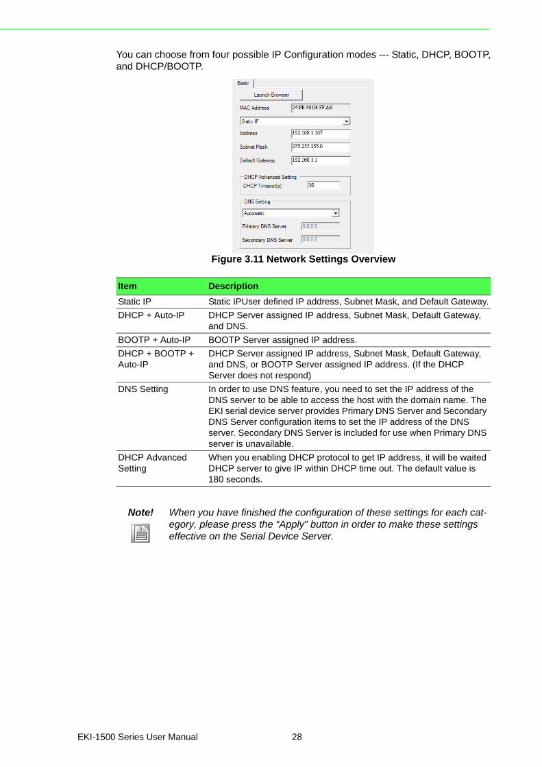
You can choose from four possible IP Configuration modes --- Static, DHCP, BOOTP,and DHCP/BOOTP.
Figure 3.11 Network Settings Overview
Item Description
Static IP Static IPUser defined IP address, Subnet Mask, and Default Gateway.
DHCP + Auto-IP DHCP Server assigned IP address, Subnet Mask, Default Gateway, and DNS.
BOOTP + Auto-IP BOOTP Server assigned IP address.
DHCP + BOOTP + Auto-IP
DHCP Server assigned IP address, Subnet Mask, Default Gateway, and DNS, or BOOTP Server assigned IP address. (If the DHCP Server does not respond)
DNS Setting In order to use DNS feature, you need to set the IP address of the DNS server to be able to access the host with the domain name. The EKI serial device server provides Primary DNS Server and Secondary DNS Server configuration items to set the IP address of the DNS server. Secondary DNS Server is included for use when Primary DNS server is unavailable.
DHCP Advanced Setting
When you enabling DHCP protocol to get IP address, it will be waited DHCP server to give IP within DHCP time out. The default value is 180 seconds.
Note! When you have finished the configuration of these settings for each cat-egory, please press the “Apply” button in order to make these settings effective on the Serial Device Server.
EKI-1500 Series User Manual 28
3.4 Administrator Settings
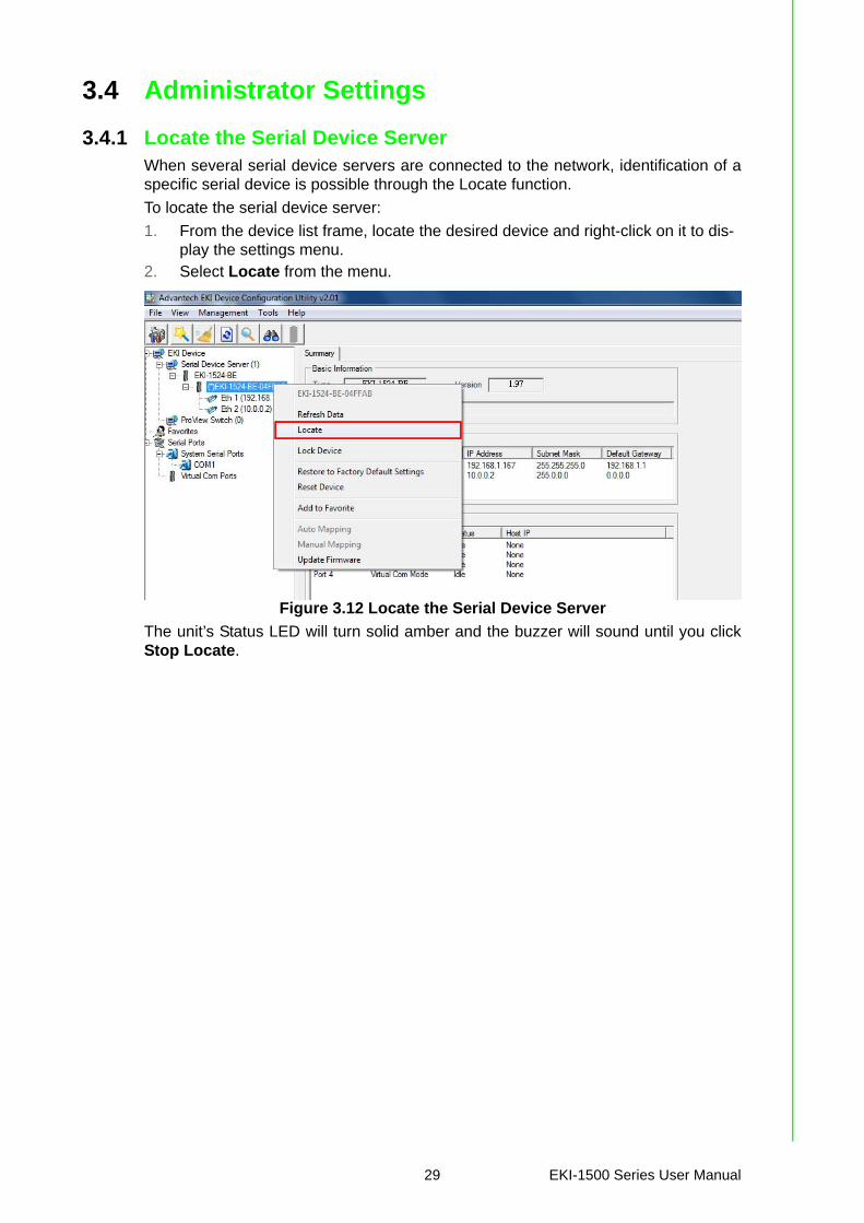
3.4.1 Locate the Serial Device ServerWhen several serial device servers are connected to the network, identification of aspecific serial device is possible through the Locate function.
To locate the serial device server:
1. From the device list frame, locate the desired device and right-click on it to dis-play the settings menu.
2. Select Locate from the menu.
Figure 3.12 Locate the Serial Device Server
The unit’s Status LED will turn solid amber and the buzzer will sound until you clickStop Locate.
29 EKI-1500 Series User Manual
3.4.2 Securing the Serial Device Server
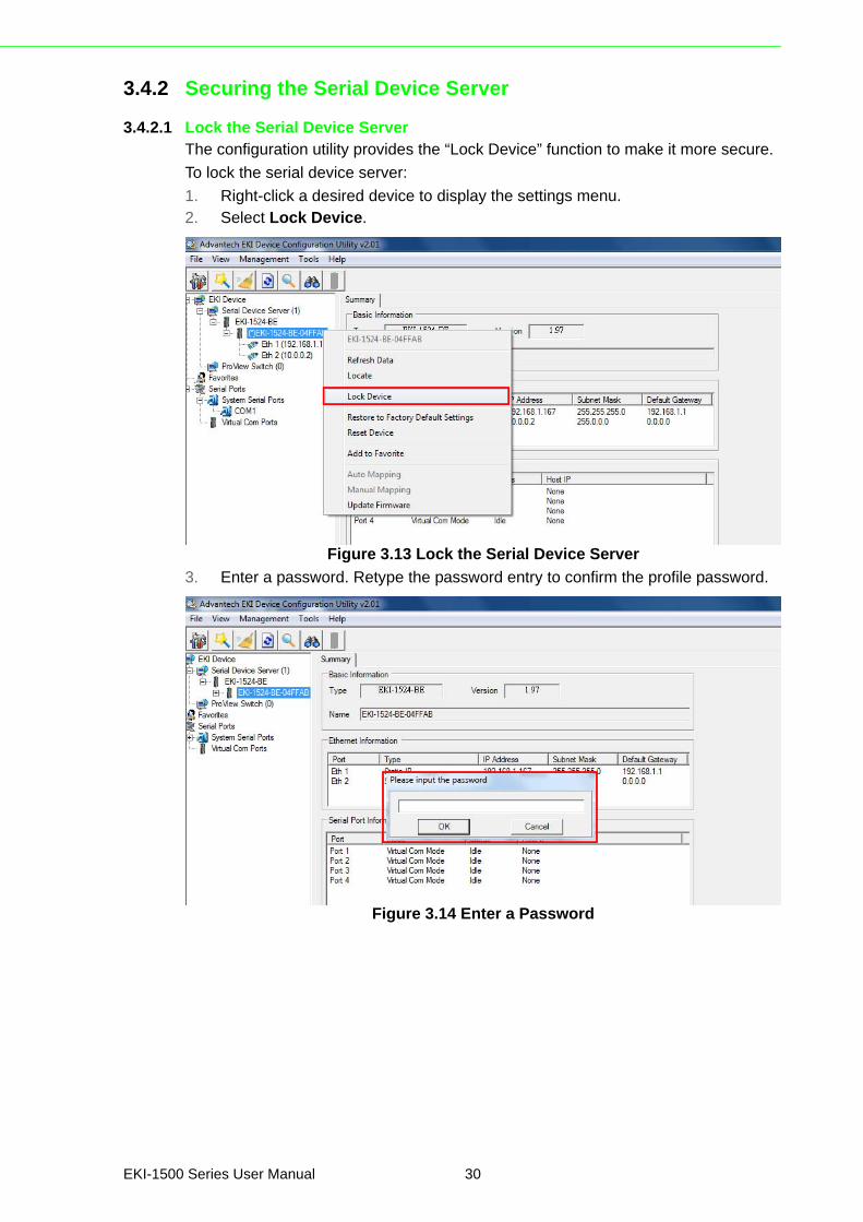
3.4.2.1 Lock the Serial Device ServerThe configuration utility provides the “Lock Device” function to make it more secure.
To lock the serial device server:
1. Right-click a desired device to display the settings menu.2. Select Lock Device.
Figure 3.13 Lock the Serial Device Server
3. Enter a password. Retype the password entry to confirm the profile password.
Figure 3.14 Enter a Password
EKI-1500 Series User Manual 30
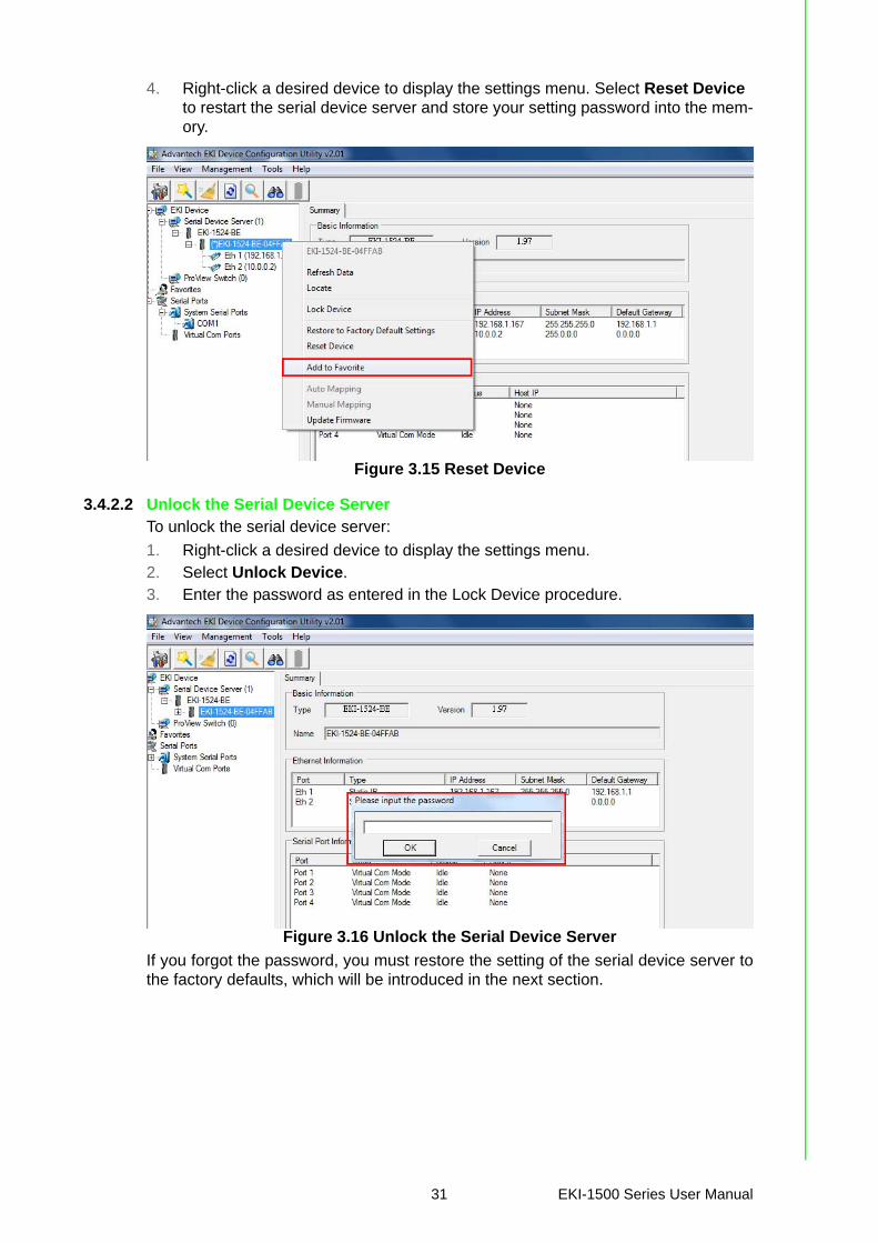
4. Right-click a desired device to display the settings menu. Select Reset Device to restart the serial device server and store your setting password into the mem-ory.
Figure 3.15 Reset Device
3.4.2.2 Unlock the Serial Device ServerTo unlock the serial device server:
1. Right-click a desired device to display the settings menu.2. Select Unlock Device.3. Enter the password as entered in the Lock Device procedure.
Figure 3.16 Unlock the Serial Device Server
If you forgot the password, you must restore the setting of the serial device server tothe factory defaults, which will be introduced in the next section.
31 EKI-1500 Series User Manual
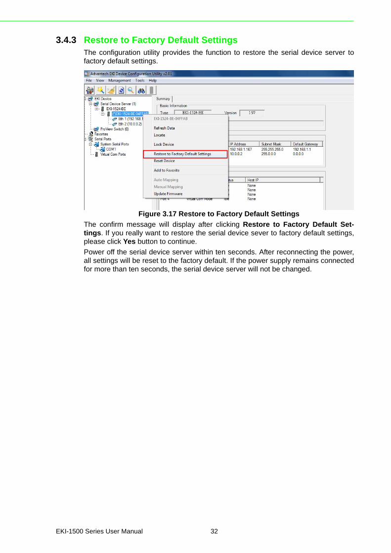
3.4.3 Restore to Factory Default SettingsThe configuration utility provides the function to restore the serial device server tofactory default settings.
Figure 3.17 Restore to Factory Default Settings
The confirm message will display after clicking Restore to Factory Default Set-tings. If you really want to restore the serial device sever to factory default settings,please click Yes button to continue.
Power off the serial device server within ten seconds. After reconnecting the power,all settings will be reset to the factory default. If the power supply remains connectedfor more than ten seconds, the serial device server will not be changed.
EKI-1500 Series User Manual 32
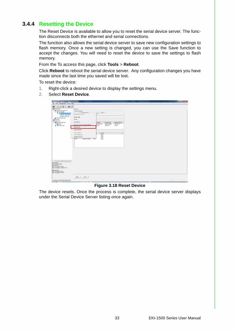
3.4.4 Resetting the DeviceThe Reset Device is available to allow you to reset the serial device server. The func-tion disconnects both the ethernet and serial connections.
The function also allows the serial device server to save new configuration settings toflash memory. Once a new setting is changed, you can use the Save function toaccept the changes. You will need to reset the device to save the settings to flashmemory.
From the To access this page, click Tools > Reboot.
Click Reboot to reboot the serial device server. Any configuration changes you havemade since the last time you saved will be lost.
To reset the device:
1. Right-click a desired device to display the settings menu.2. Select Reset Device.
Figure 3.18 Reset Device
The device resets. Once the process is complete, the serial device server displaysunder the Serial Device Server listing once again.
33 EKI-1500 Series User Manual

3.4.5 Add to FavoriteThe Add to Favorite function allows to easily map available devices to Favorite’s. Bybookmarking specific devices, you can create quickly accessible shortcuts for exist-ing critical devices from the vast pool of locally or remotely networked EKI devices.
Figure 3.19 Add to Favorite
3.4.6 Auto MappingSee “Auto Mapping” on page 44 for further details.
3.4.7 Manual MappingSee “Manual Mapping” on page 46 for further details.
EKI-1500 Series User Manual 34

3.4.8 Update FirmwareAdvantech continually upgrades its firmware to keep up with the ever-expandingworld of computing. You can use the update firmware function in the utility to carryout the upgrade procedure. Please access Advantech’s website: http://www.advan-tech.com to download the latest version of the firmware. Before updating the firm-ware, make sure that your host’s Network domain is as same as the serial deviceserver or the host can establish the TCP connection to the serial device server.
To update firmware:
1. Right-click a desired device to display the settings menu.2. Select Update Firmware.
Figure 3.20 Update Firmware
3. Select the firmware file you want to update.Wait for a few seconds for the firmware to finish updating. After the update has com-pleted, click on the OK button. The serial device server will restart automatically.
Note! Be sure that the host PC Ethernet network domain is as same as the EKI-1500 Series serial device server or the host PC can establish the TCP connection with the serial device server while doing the updating firmware process.
35 EKI-1500 Series User Manual

Chapter 4
4Selecting An Operating Mode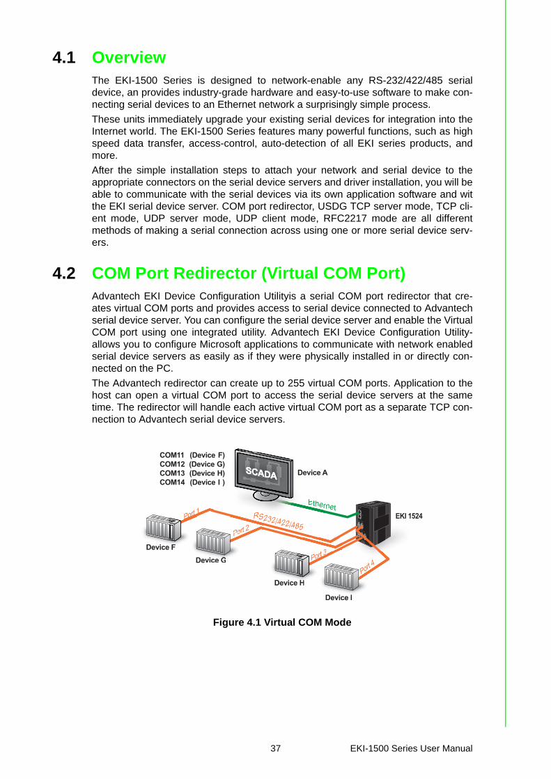
4.1 OverviewThe EKI-1500 Series is designed to network-enable any RS-232/422/485 serialdevice, an provides industry-grade hardware and easy-to-use software to make con-necting serial devices to an Ethernet network a surprisingly simple process.
These units immediately upgrade your existing serial devices for integration into theInternet world. The EKI-1500 Series features many powerful functions, such as highspeed data transfer, access-control, auto-detection of all EKI series products, andmore.
After the simple installation steps to attach your network and serial device to theappropriate connectors on the serial device servers and driver installation, you will beable to communicate with the serial devices via its own application software and witthe EKI serial device server. COM port redirector, USDG TCP server mode, TCP cli-ent mode, UDP server mode, UDP client mode, RFC2217 mode are all differentmethods of making a serial connection across using one or more serial device serv-ers.
4.2 COM Port Redirector (Virtual COM Port)Advantech EKI Device Configuration Utilityis a serial COM port redirector that cre-ates virtual COM ports and provides access to serial device connected to Advantechserial device server. You can configure the serial device server and enable the VirtualCOM port using one integrated utility. Advantech EKI Device Configuration Utility-allows you to configure Microsoft applications to communicate with network enabledserial device servers as easily as if they were physically installed in or directly con-nected on the PC.
The Advantech redirector can create up to 255 virtual COM ports. Application to thehost can open a virtual COM port to access the serial device servers at the sametime. The redirector will handle each active virtual COM port as a separate TCP con-nection to Advantech serial device servers.
Figure 4.1 Virtual COM Mode
PWR2P-Fail DC12-48V
PWR1
V2- V2+V1- V1+ 1A@24V
1
2
4
LAN
Default
TxRx
TxRx
TxRx
TxRx
Rx
P1 P2 Status
Serial PortsEKI - 1528CI
EKI 1524
EthernetEther
Device ASCADASCADASSSSCCAAADDAAAAASSCCAADDAAASSSSSCCCAAADDAAASSSCCAADDASCADA
COM11 (Device F)COM12 (Device G)COM13 (Device H)COM14 (Device I )
Port 1
Port 4
Port 2
Port 3
Device H
Device I
Device GDevice F
Port 1rt 1
Device
PorPort 2
cee GG
PorPor
Device FF
t 3
DevicePort 4
ce II
Port 33
e HH
Devic
RS232/422/485
37 EKI-1500 Series User Manual

The EKI-1500 Series provides Multi-access function through an Ethernet connectionpath, allowing a maximum of five connections to open one serial port simultaneously.In this mode all connections must use the same serial setting. If one serial settingwithin this configuration is configured differently, the data communication will notfunction correctly.
Figure 4.2 Configuring Virtual COM Mode
The Host Idle Timeout setting monitors the connection between the host and thedevice. If the Host Idle Timeout setting time is reached, the device server will releasethe resources allocated to the port mapping. This prevents a stalled host from affect-ing the connective device.
The Multi-access function has two modes. One is Normal mode and the other isRound-Robin mode.
4.2.1 Normal modeBy disabling the Response Timeout parameter, the EKI-1500 Series will operate innormal mode. When multiple hosts simultaneously open the serial port, only the firstconnected host obtain management control, the remaining connections only havedata communication function. Each serial port supports up to five simultaneous con-nections, so multiple hosts can transmit/receive data to/from the same serial portsimultaneously. Every host can transmit data to the same serial port, and the EKI-1500 Series will also transmit data to every hosts. When the multiple hosts transmitdata to the same serial port at the same time, the received data from Ethernet andthe outputs of serial port are mixed. When the EKI-1500 Series receives data fromserial port, the data will also be transmitted to the connected hosts simultaneously.
4.2.2 Round-Robin modeBy enabling the Response Timeout parameter, the EKI-1500 Series Series operatesin “Round-Robin mode”. Each serial port supports up to five simultaneous connec-tions allowing hosts to simultaneously transmit/receive data to/from the same serialport. Every host can simultaneously transmit data to the same serial port, EKI-1500Series processes the data in the order arrived. The EKI-1500 Series processes thefirst host’s request and replies. The serial device server determines the end of theserial acknowledgement through a response timeout. When EKI-1500 Series serialdevice server does not receive a response from the serial port after a response time-out query, the device replies with an acknowledgement and then processes the nexthost request. With an increased number of hosts, response time may be lengthy,increasing the period of the Response Timeout.
Frame Break is an important parameter for Round Robin mode. The parameter is asmart method of reducing ineffective waiting periods and streamlining the transmis-sion process.
If the Frame Break function is disabled, EKI-1500 Series devices will wait for a“Response Timeout” period, whether or not the device has transmitted data. Duringthis period, the host commands are queued and processed in the order received.
If Frame Break is enabled, the serial port idle is longer than the Frame Break period.The EKI-1500 Series assumes the communication is completed and continues withthe next query. This is an efficient way to reduce waiting time and improve perfor-mance.
EKI-1500 Series User Manual 38
4.3 USDG Data ModeThe EKI-1500 Series can funciton as either a Data TCP server or a Data TCP client.Both operations support TCP and UDP protocol. The EKI-1500 Series allows you totreat your serial devices as if they were networking devices. You can issue com-mands or transmit data from serial devices, connected to a EKI-1500 Series device,to any devices that are connected to the Internet.
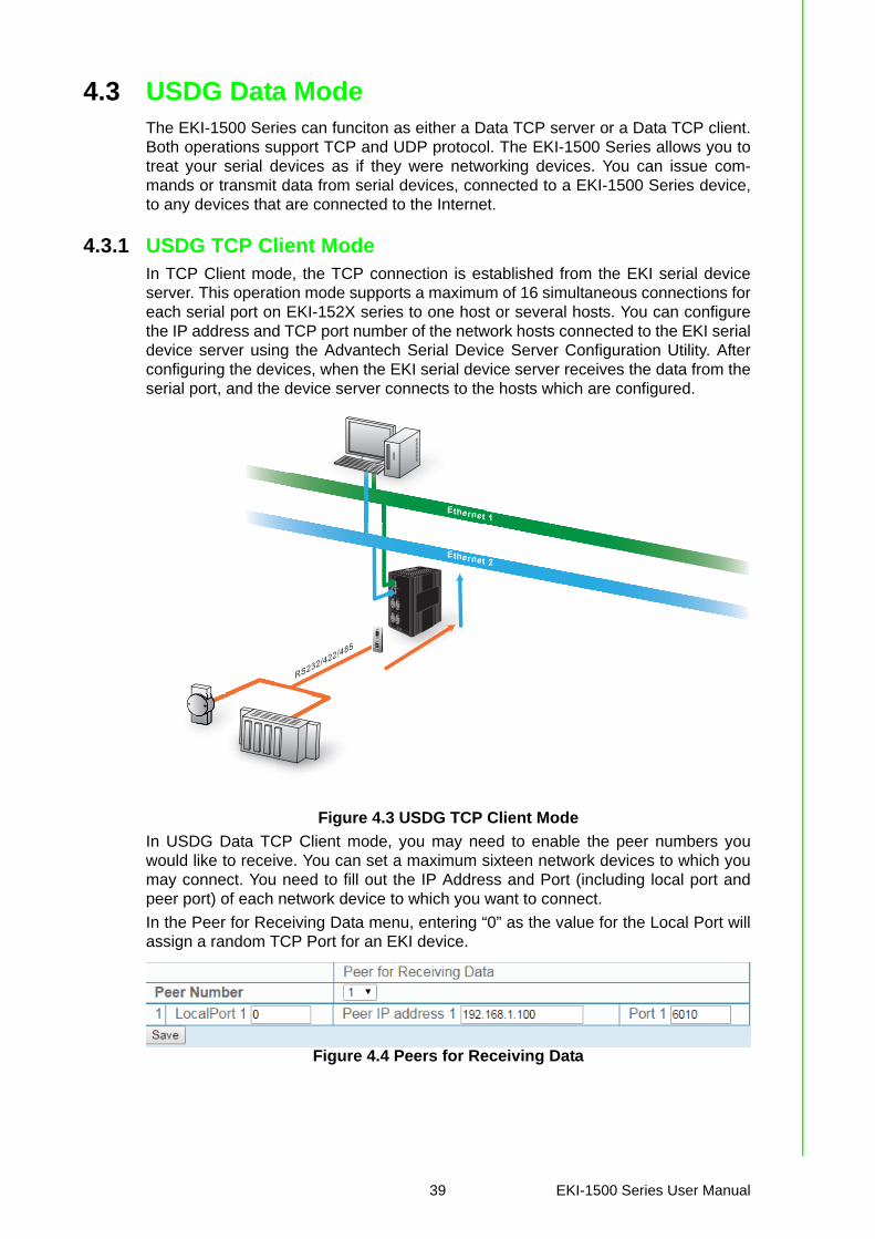
4.3.1 USDG TCP Client ModeIn TCP Client mode, the TCP connection is established from the EKI serial deviceserver. This operation mode supports a maximum of 16 simultaneous connections foreach serial port on EKI-152X series to one host or several hosts. You can configurethe IP address and TCP port number of the network hosts connected to the EKI serialdevice server using the Advantech Serial Device Server Configuration Utility. Afterconfiguring the devices, when the EKI serial device server receives the data from theserial port, and the device server connects to the hosts which are configured.
Figure 4.3 USDG TCP Client Mode
In USDG Data TCP Client mode, you may need to enable the peer numbers youwould like to receive. You can set a maximum sixteen network devices to which youmay connect. You need to fill out the IP Address and Port (including local port andpeer port) of each network device to which you want to connect.
In the Peer for Receiving Data menu, entering “0” as the value for the Local Port willassign a random TCP Port for an EKI device.
Figure 4.4 Peers for Receiving Data
PWR2P-Fail DC12-48V
PWR1
V2- V2+V1- V1+ 1A@24V
1
2
4
LAN
Default
TxRx
TxRx
TxRx
TxRx
P1 P2 Status
Serial PortsEKI - 1524
Ethernet 1
RS232/422/485
Ethernet 2
39 EKI-1500 Series User Manual
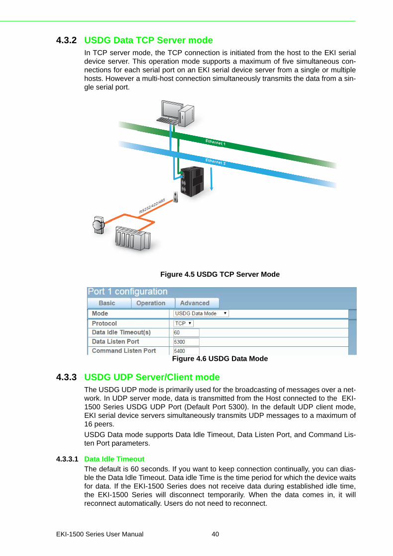
4.3.2 USDG Data TCP Server modeIn TCP server mode, the TCP connection is initiated from the host to the EKI serialdevice server. This operation mode supports a maximum of five simultaneous con-nections for each serial port on an EKI serial device server from a single or multiplehosts. However a multi-host connection simultaneously transmits the data from a sin-gle serial port.
Figure 4.5 USDG TCP Server Mode
Figure 4.6 USDG Data Mode
4.3.3 USDG UDP Server/Client modeThe USDG UDP mode is primarily used for the broadcasting of messages over a net-work. In UDP server mode, data is transmitted from the Host connected to the EKI-1500 Series USDG UDP Port (Default Port 5300). In the default UDP client mode,EKI serial device servers simultaneously transmits UDP messages to a maximum of16 peers.
USDG Data mode supports Data Idle Timeout, Data Listen Port, and Command Lis-ten Port parameters.
4.3.3.1 Data Idle TimeoutThe default is 60 seconds. If you want to keep connection continually, you can dias-ble the Data Idle Timeout. Data idle Time is the time period for which the device waitsfor data. If the EKI-1500 Series does not receive data during established idle time,the EKI-1500 Series will disconnect temporarily. When the data comes in, it willreconnect automatically. Users do not need to reconnect.
PWR2P-Fail DC12-48V
PWR1
V2- V2+V1- V1+ 1A@24V
1
2
4
LAN
Default
TxRx
TxRx
TxRx
TxRx
P1 P2 Status
Serial PortsEKI - 1524
Ethernet 1
RS232/422/485
Ethernet 2
EKI-1500 Series User Manual 40

4.3.3.2 Data Listen PortThe TCP/UDP port number represents the source port number, and the number isused to identify the channel for remote initiating connections. The port range is 1024-65533. If an unknown caller wants to connect to the system and request services,they must define the TCP/UDP port to carry a long-term conversation.
Each node on a TCP/IP network has an IP address, and each IP address can allowconnection on one or more TCP port. The well-known TCP ports are those that havebeen defined; for example, port 23 is used for Telnet connections. There are alsocustom sockets that users and developers define for their specific needs. The defaultTCP/UDP port of the EKI-1500 Series Port1 is 5300, Port2 is 5301, etc. Users canadjust them according to preference or application. Each port has its own data listenport to accept the connection requests of other network device. The data listen portcannot be set to the same value. You can transmit/receive data to/from devices viathe data listen port.
4.3.3.3 Command Listen PortEach port has its own command listen port to accept connection requests from othernetwork devices, so the command listen port cannot be set to the same value. TheCommand Listen Port is different from the Data Listen port. <Default Port is 5400>
4.4 USDG Control ModeIn controlling mode, the EKI serial device server presents a modem interface to theattached serial device: it accepts AT-style modem commands to connect / disconnectto other networking device.
If you want a serial device running application program to connect/disconnect to dif-ferent devices on request, this function is available through the USDG Control mode.
Figure 4.7 USDG Control Mode
4.4.1 Hangup CharacterThe default character is “+”. After you have connected to another serial device an viaEKI device, you may need to disconnect, using the command “+++”. To do this, press“+” three times and wait for the Guard timeout <default value is 1000ms>; the devicewill disconnect. You can set “Guard Time” to define the idle time.
41 EKI-1500 Series User Manual
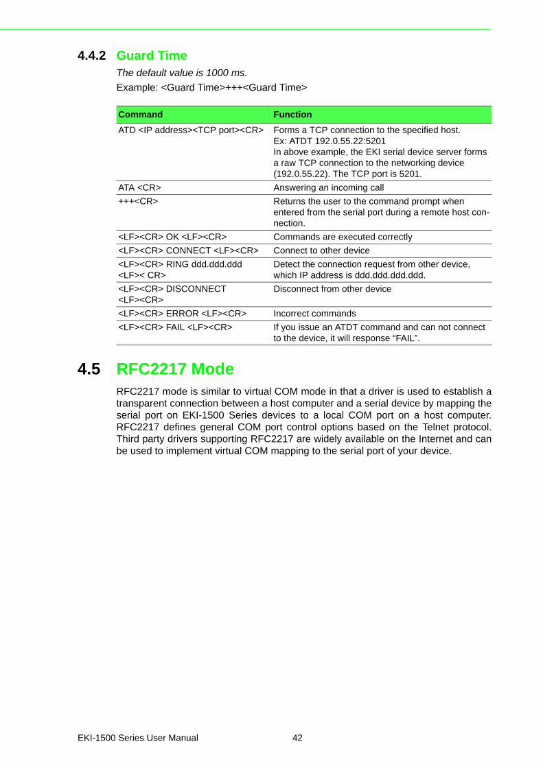
4.4.2 Guard TimeThe default value is 1000 ms.
Example: <Guard Time>+++<Guard Time>
4.5 RFC2217 ModeRFC2217 mode is similar to virtual COM mode in that a driver is used to establish atransparent connection between a host computer and a serial device by mapping theserial port on EKI-1500 Series devices to a local COM port on a host computer.RFC2217 defines general COM port control options based on the Telnet protocol.Third party drivers supporting RFC2217 are widely available on the Internet and canbe used to implement virtual COM mapping to the serial port of your device.
Command Function
ATD <IP address><TCP port><CR> Forms a TCP connection to the specified host.Ex: ATDT 192.0.55.22:5201In above example, the EKI serial device server forms a raw TCP connection to the networking device (192.0.55.22). The TCP port is 5201.
ATA <CR> Answering an incoming call
+++<CR> Returns the user to the command prompt when entered from the serial port during a remote host con-nection.
<LF><CR> OK <LF><CR> Commands are executed correctly
<LF><CR> CONNECT <LF><CR> Connect to other device
<LF><CR> RING ddd.ddd.ddd <LF>< CR>
Detect the connection request from other device, which IP address is ddd.ddd.ddd.ddd.
<LF><CR> DISCONNECT <LF><CR>
Disconnect from other device
<LF><CR> ERROR <LF><CR> Incorrect commands
<LF><CR> FAIL <LF><CR> If you issue an ATDT command and can not connect to the device, it will response “FAIL”.
EKI-1500 Series User Manual 42

Chapter 5
5Setting up Virtual COM Port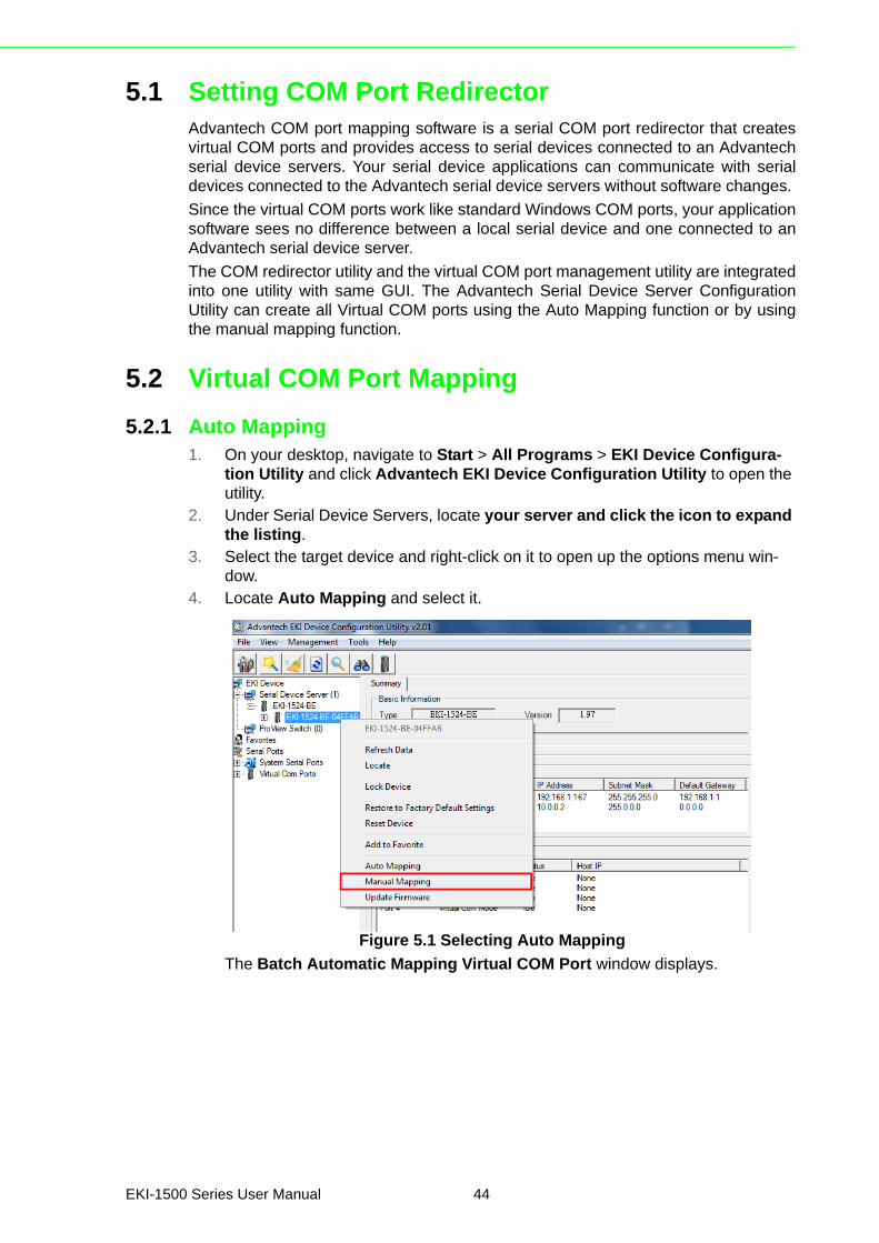
5.1 Setting COM Port RedirectorAdvantech COM port mapping software is a serial COM port redirector that createsvirtual COM ports and provides access to serial devices connected to an Advantechserial device servers. Your serial device applications can communicate with serialdevices connected to the Advantech serial device servers without software changes.
Since the virtual COM ports work like standard Windows COM ports, your applicationsoftware sees no difference between a local serial device and one connected to anAdvantech serial device server.
The COM redirector utility and the virtual COM port management utility are integratedinto one utility with same GUI. The Advantech Serial Device Server ConfigurationUtility can create all Virtual COM ports using the Auto Mapping function or by usingthe manual mapping function.
5.2 Virtual COM Port Mapping
5.2.1 Auto Mapping1. On your desktop, navigate to Start > All Programs > EKI Device Configura-
tion Utility and click Advantech EKI Device Configuration Utility to open the utility.
2. Under Serial Device Servers, locate your server and click the icon to expand the listing.
3. Select the target device and right-click on it to open up the options menu win-dow.
4. Locate Auto Mapping and select it.
Figure 5.1 Selecting Auto Mapping
The Batch Automatic Mapping Virtual COM Port window displays.
EKI-1500 Series User Manual 44
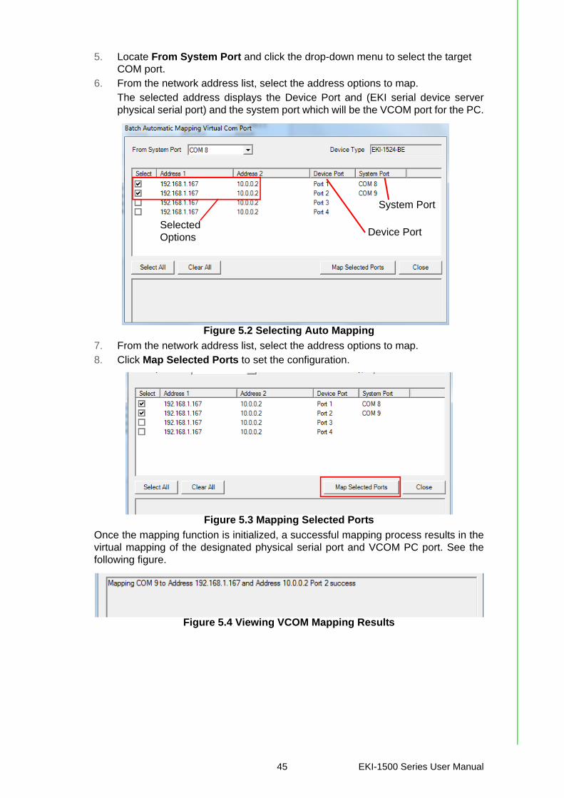
5. Locate From System Port and click the drop-down menu to select the target COM port.
6. From the network address list, select the address options to map.The selected address displays the Device Port and (EKI serial device serverphysical serial port) and the system port which will be the VCOM port for the PC.
Figure 5.2 Selecting Auto Mapping
7. From the network address list, select the address options to map.8. Click Map Selected Ports to set the configuration.
Figure 5.3 Mapping Selected Ports
Once the mapping function is initialized, a successful mapping process results in thevirtual mapping of the designated physical serial port and VCOM PC port. See thefollowing figure.
Figure 5.4 Viewing VCOM Mapping Results
System Port
Device PortSelectedOptions
45 EKI-1500 Series User Manual
5.2.2 Manual Mapping1. On your desktop, navigate to Start > All Programs > EKI Device Configura-
tion Utility and click Advantech EKI Device Configuration Utility to open the utility.
2. Under Serial Device Servers, locate your server and click the icon to expand the listing.
3. Select the target device and right-click on it to open up the options menu win-dow.
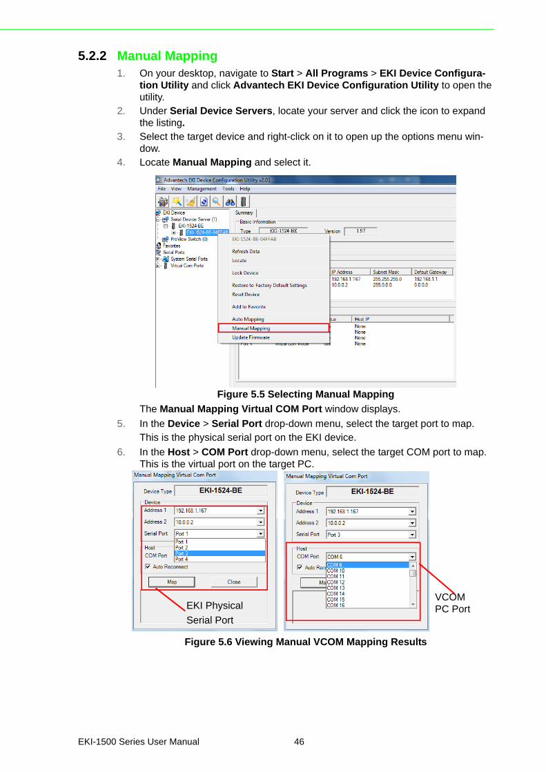
4. Locate Manual Mapping and select it.
Figure 5.5 Selecting Manual Mapping
The Manual Mapping Virtual COM Port window displays.
5. In the Device > Serial Port drop-down menu, select the target port to map.This is the physical serial port on the EKI device.
6. In the Host > COM Port drop-down menu, select the target COM port to map. This is the virtual port on the target PC.
Figure 5.6 Viewing Manual VCOM Mapping Results
VCOMPC PortEKI Physical
Serial Port
EKI-1500 Series User Manual 46
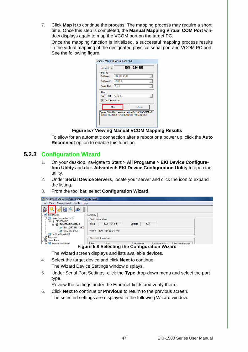
7. Click Map it to continue the process. The mapping process may require a short time. Once this step is completed, the Manual Mapping Virtual COM Port win-dow displays again to map the VCOM port on the target PC.Once the mapping function is initialized, a successful mapping process resultsin the virtual mapping of the designated physical serial port and VCOM PC port.See the following figure.
Figure 5.7 Viewing Manual VCOM Mapping Results
To allow for an automatic connection after a reboot or a power up, click the AutoReconnect option to enable this function.
5.2.3 Configuration Wizard1. On your desktop, navigate to Start > All Programs > EKI Device Configura-
tion Utility and click Advantech EKI Device Configuration Utility to open the utility.
2. Under Serial Device Servers, locate your server and click the icon to expand the listing.
3. From the tool bar, select Configuration Wizard.
Figure 5.8 Selecting the Configuration Wizard
The Wizard screen displays and lists available devices.
4. Select the target device and click Next to continue.The Wizard Device Settings window displays.
5. Under Serial Port Settings, click the Type drop-down menu and select the port type.Review the settings under the Ethernet fields and verify them.
6. Click Next to continue or Previous to return to the previous screen.The selected settings are displayed in the following Wizard window.
47 EKI-1500 Series User Manual

7. Locate the radio button correlating to the target port to modify and click on it to select it.Verify the Device Port (EKI device physical serial port) and System Port (virtualCOM port for PC) settings before continuing.
8. Click Finish to complete the process. A Wizard complete! screen displays indi-cating the completion of a successful procedure.
5.2.4 Confirming Virtual COM Settings1. On your desktop, navigate to Start > All Programs > EKI Device Configura-
tion Utility and click Advantech EKI Device Configuration Utility to open the utility.
2. Locate Serial Ports menu in the menu pane and click on the Expand icon next to Virtual COM Ports to view a list of the mapped ports.
3. Select a VCOM port to view its settings.
Figure 5.9 Serial Port Listing on EKI Device
For the next step, you will need to open the device manager on your system.Using the Device Manager, you can both view and change the COM port set-tings.
4. On your desktop, click on the Start button and then on Control Panel. A win-dow displays showing all the available control panels.
5. Click on Hardware and Sound (Hardware). A list of all available hardware con-figuration options displays.
6. Under Devices and Printers, click on the Device Manager link. A new window displays showing a list of all the available devices on your computer.
7. Locate Ports (COM & LPT) and click on the expand icon. A list of all available serial and parallel port devices display.
Note! The following instructions were developed in a Windows 7 environment; the Windows XP equivalent is displayed in parentheses (). Instructions may vary according to the operating system used.
EKI-1500 Series User Manual 48
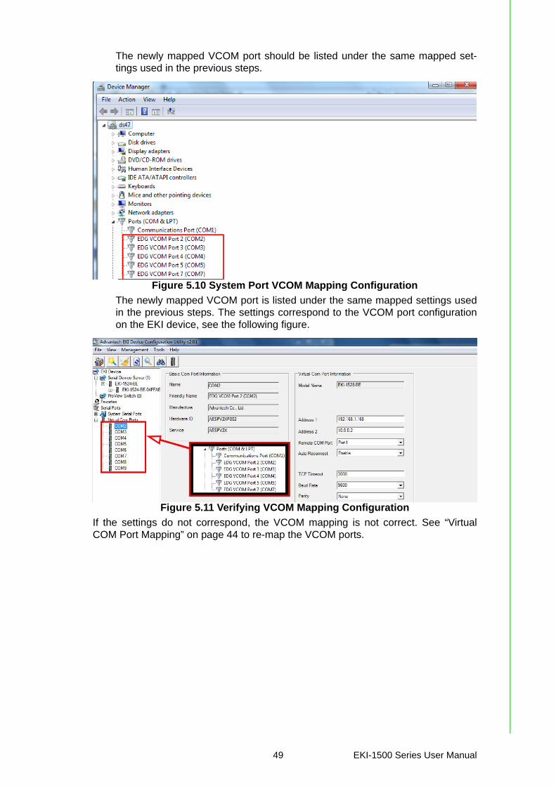
The newly mapped VCOM port should be listed under the same mapped set-tings used in the previous steps.
Figure 5.10 System Port VCOM Mapping Configuration
The newly mapped VCOM port is listed under the same mapped settings usedin the previous steps. The settings correspond to the VCOM port configurationon the EKI device, see the following figure.
Figure 5.11 Verifying VCOM Mapping Configuration
If the settings do not correspond, the VCOM mapping is not correct. See “VirtualCOM Port Mapping” on page 44 to re-map the VCOM ports.
49 EKI-1500 Series User Manual

5.2.5 Removing VCOM Ports1. On your desktop, navigate to Start > All Programs > EKI Device Configura-
tion Utility and click Advantech EKI Device Configuration Utility to open the utility.
2. Under Serial Ports, click the expand icon on Virtual COM Ports to view the con-figured port list.
3. Locate the port to remove and right-click on it to open the options menu.4. Scroll down to Remove This Port and click on it to initiate the procedure.
Figure 5.12 Remove VCOM Port
A Remove Port confirmation window displays.
5. Click OK to continue with the removal process or Cancel to return to the previ-ous menu.
Once the procedure is completed, a prompt displays the successful removal of theport from the VCOM mapping list.
5.2.6 Exporting and Importing VCOM MappingImporting and exporting Virtual COM Port Mapping is useful when the factory hasalready used a number of serial device servers in VCOM mode. You can easilyupgrade to a new utility, and don’t need to re-map the Virtual COM Ports. For exam-ple, when you would like to upgrade from Utility 1.71 to Utility 2.01, you can exportyour own mapped Virtual COM Ports in Utility 1.71 and save them as a *.cpm file.
After upgrading to Utility 2.01, import your *.cpm file and restore your own VirtualCOM Ports.
1. On your desktop, navigate to Start > All Programs > EKI Device Configura-tion Utility and click Advantech EKI Device Configuration Utility to open the utility.
2. Locate Serial Ports menu in the menu pane and click on the Expand icon next to Virtual COM Ports to view a list of the mapped ports.
Note! This Virtual COM Port Mapping tool can only recover Virtual COM Ports that have been mapped previously. For newly installed serial device servers, please follow the virtual COM Port mapping steps.
EKI-1500 Series User Manual 50

3. Select a VCOM port.4. Click Import Virtual COM Port Mapping or Export Virtual COM Port Mapping
in the File menu.
5.3 Running a Diagnostic TestThe loopback test allows you to determine if the EKI serial device server is config-ured correctly to identify any failed nodes in the network. The test allows you to senda signal from the server and return (looped back) it back to the server.
1. Connect the loopack connector to a COM port on the EKI serial device server.2. On your desktop, navigate to Start > All Programs > EKI Device Configura-
tion Utility and click Advantech EKI Device Configuration Utility to open the utility.
3. Under Serial Ports, click the expand icon on Virtual COM Ports to view the con-figured port list.
4. Open the ICOMToolsPlus utility to open the EKI serial device server settings.5. Set the COM port configuration to match the Port Configuration.6. Click the Start menu.A successful loopback test incrementally displays the Bytes/sec values on both dis-played menus.
51 EKI-1500 Series User Manual

Chapter 6
6Web Interface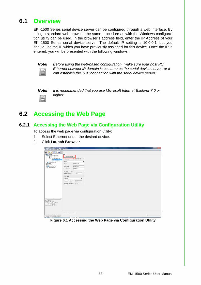
6.1 OverviewEKI-1500 Series serial device server can be configured through a web interface. Byusing a standard web browser, the same procedure as with the Windows configura-tion utility can be used. In the browser’s address field, enter the IP Address of yourEKI-1500 Series serial device server. The default IP setting is 10.0.0.1, but youshould use the IP which you have previously assigned for this device. Once the IP isentered, you will be presented with the following windows.
6.2 Accessing the Web Page
6.2.1 Accessing the Web Page via Configuration UtilityTo access the web page via configuration utility:
1. Select Ethernet under the desired device.2. Click Launch Browser.
Figure 6.1 Accessing the Web Page via Configuration Utility
Note! Before using the web-based configuration, make sure your host PC Ethernet network IP domain is as same as the serial device server, or it can establish the TCP connection with the serial device server.
Note! It is recommended that you use Microsoft Internet Explorer 7.0 or higher.
53 EKI-1500 Series User Manual
6.2.2 Accessing the Web Page via Web BrowserOnce the device is installed and connected, power on the device. The following infor-mation guides you through the logging in process.
1. Launch your web browser on the PC.2. In the browser’s address bar, type the device’s default IP address (Eth1:
10.0.0.1, Eth2: 10.0.0.2).The main menu is shown.
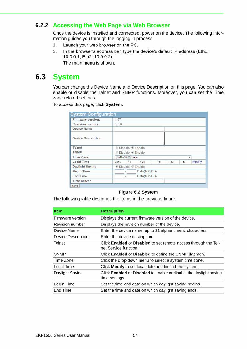
6.3 SystemYou can change the Device Name and Device Description on this page. You can alsoenable or disable the Telnet and SNMP functions. Moreover, you can set the Timezone related settings.
To access this page, click System.
Figure 6.2 System
The following table describes the items in the previous figure.
Item Description
Firmware version Displays the current firmware version of the device.
Revision number Displays the revision number of the device.
Device Name Enter the device name: up to 31 alphanumeric characters.
Device Description Enter the device description.
Telnet Click Enabled or Disabled to set remote access through the Tel-net Service function.
SNMP Click Enabled or Disabled to define the SNMP daemon.
Time Zone Click the drop-down menu to select a system time zone.
Local Time Click Modify to set local date and time of the system.
Daylight Saving Click Enabled or Disabled to enable or disable the daylight saving time settings.
Begin Time Set the time and date on which daylight saving begins.
End Time Set the time and date on which daylight saving ends.
EKI-1500 Series User Manual 54
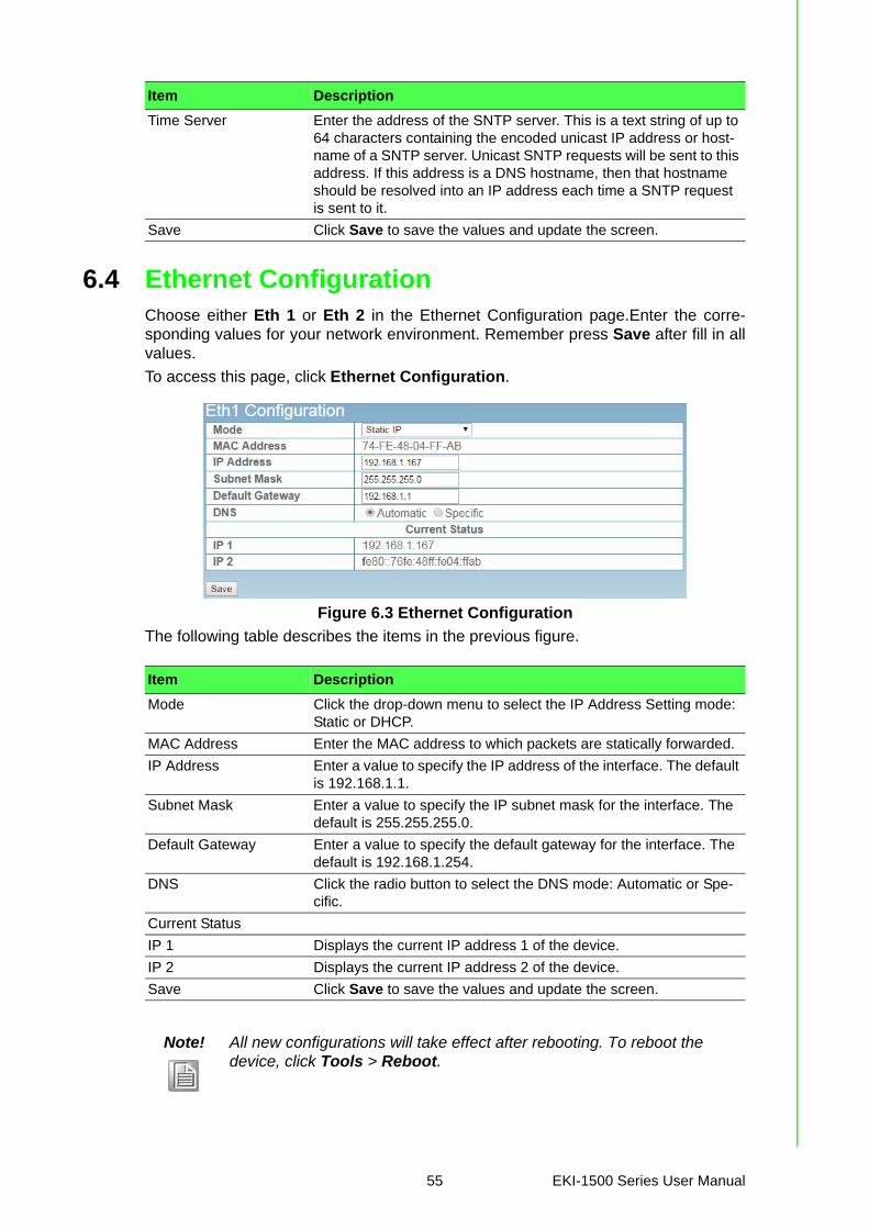
6.4 Ethernet ConfigurationChoose either Eth 1 or Eth 2 in the Ethernet Configuration page.Enter the corre-sponding values for your network environment. Remember press Save after fill in allvalues.
To access this page, click Ethernet Configuration.
Figure 6.3 Ethernet Configuration
The following table describes the items in the previous figure.
Time Server Enter the address of the SNTP server. This is a text string of up to 64 characters containing the encoded unicast IP address or host-name of a SNTP server. Unicast SNTP requests will be sent to this address. If this address is a DNS hostname, then that hostname should be resolved into an IP address each time a SNTP request is sent to it.
Save Click Save to save the values and update the screen.
Item Description
Item Description
Mode Click the drop-down menu to select the IP Address Setting mode: Static or DHCP.
MAC Address Enter the MAC address to which packets are statically forwarded.
IP Address Enter a value to specify the IP address of the interface. The default is 192.168.1.1.
Subnet Mask Enter a value to specify the IP subnet mask for the interface. The default is 255.255.255.0.
Default Gateway Enter a value to specify the default gateway for the interface. The default is 192.168.1.254.
DNS Click the radio button to select the DNS mode: Automatic or Spe-cific.
Current Status
IP 1 Displays the current IP address 1 of the device.
IP 2 Displays the current IP address 2 of the device.
Save Click Save to save the values and update the screen.
Note! All new configurations will take effect after rebooting. To reboot the device, click Tools > Reboot.
55 EKI-1500 Series User Manual
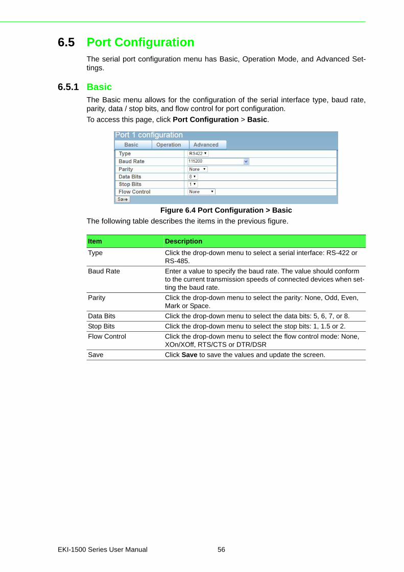
6.5 Port ConfigurationThe serial port configuration menu has Basic, Operation Mode, and Advanced Set-tings.
6.5.1 BasicThe Basic menu allows for the configuration of the serial interface type, baud rate,parity, data / stop bits, and flow control for port configuration.
To access this page, click Port Configuration > Basic.
Figure 6.4 Port Configuration > Basic
The following table describes the items in the previous figure.
Item Description
Type Click the drop-down menu to select a serial interface: RS-422 or RS-485.
Baud Rate Enter a value to specify the baud rate. The value should conform to the current transmission speeds of connected devices when set-ting the baud rate.
Parity Click the drop-down menu to select the parity: None, Odd, Even, Mark or Space.
Data Bits Click the drop-down menu to select the data bits: 5, 6, 7, or 8.
Stop Bits Click the drop-down menu to select the stop bits: 1, 1.5 or 2.
Flow Control Click the drop-down menu to select the flow control mode: None, XOn/XOff, RTS/CTS or DTR/DSR
Save Click Save to save the values and update the screen.
EKI-1500 Series User Manual 56
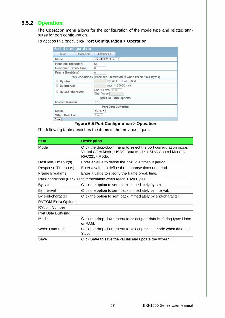
6.5.2 OperationThe Operation menu allows for the configuration of the mode type and related attri-butes for port configuration.
To access this page, click Port Configuration > Operation.
Figure 6.5 Port Configuration > Operation
The following table describes the items in the previous figure.
Item Description
Mode Click the drop-down menu to select the port configuration mode: Virtual COM Mode, USDG Data Mode, USDG Control Mode or RFC2217 Mode.
Host Idle Timeout(s) Enter a value to define the host idle timeout period.
Response Timeout(s) Enter a value to define the response timeout period.
Frame Break(ms) Enter a value to specify the frame break time.
Pack conditions (Pack sent immediately when reach 1024 Bytes)
By size Click the option to sent pack immediately by size.
By interval Click the option to sent pack immediately by interval.
By end-character Click the option to sent pack immediately by end-character.
RVCOM Extra Options
RVcom Number
Port Data Buffering
Media Click the drop-down menu to select port data buffering type: None or RAM.
When Data Full Click the drop-down menu to select process mode when data full: Stop.
Save Click Save to save the values and update the screen.
57 EKI-1500 Series User Manual
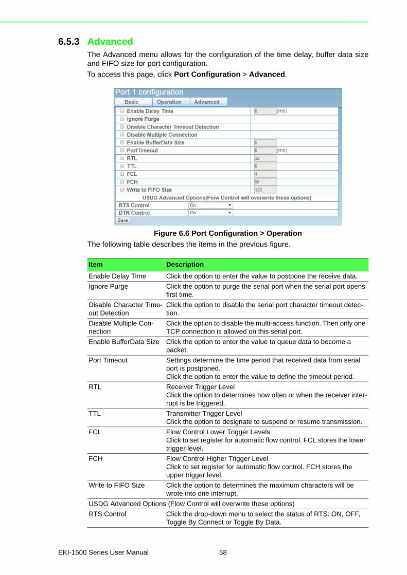
6.5.3 AdvancedThe Advanced menu allows for the configuration of the time delay, buffer data sizeand FIFO size for port configuration.
To access this page, click Port Configuration > Advanced.
Figure 6.6 Port Configuration > Operation
The following table describes the items in the previous figure.
Item Description
Enable Delay Time Click the option to enter the value to postpone the receive data.
Ignore Purge Click the option to purge the serial port when the serial port opens first time.
Disable Character Time-out Detection
Click the option to disable the serial port character timeout detec-tion.
Disable Multiple Con-nection
Click the option to disable the multi-access function. Then only one TCP connection is allowed on this serial port.
Enable BufferData Size Click the option to enter the value to queue data to become a packet.
Port Timeout Settings determine the time period that received data from serial port is postponed.Click the option to enter the value to define the timeout period.
RTL Receiver Trigger LevelClick the option to determines how often or when the receiver inter-rupt is be triggered.
TTL Transmitter Trigger LevelClick the option to designate to suspend or resume transmission.
FCL Flow Control Lower Trigger LevelsClick to set register for automatic flow control. FCL stores the lower trigger level.
FCH Flow Control Higher Trigger LevelClick to set register for automatic flow control. FCH stores the upper trigger level.
Write to FIFO Size Click the option to determines the maximum characters will be wrote into one interrupt.
USDG Advanced Options (Flow Control will overwrite these options)
RTS Control Click the drop-down menu to select the status of RTS: ON, OFF, Toggle By Connect or Toggle By Data.
EKI-1500 Series User Manual 58
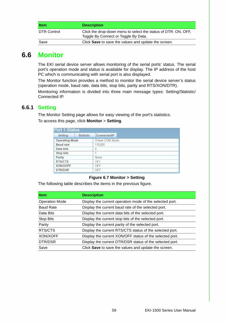
6.6 MonitorThe EKI serial device server allows monitoring of the serial ports’ status. The serialport’s operation mode and status is available for display. The IP address of the hostPC which is communicating with serial port is also displayed.
The Monitor function provides a method to monitor the serial device server’s status(operation mode, baud rate, data bits, stop bits, parity and RTS/XON/DTR).
Monitoring information is divided into three main message types: Setting/Statistic/Connected IP.
6.6.1 SettingThe Monitor Setting page allows for easy viewing of the port’s statistics.
To access this page, click Monitor > Setting.
Figure 6.7 Monitor > Setting
The following table describes the items in the previous figure.
DTR Control Click the drop-down menu to select the status of DTR: ON, OFF, Toggle By Connect or Toggle By Data.
Save Click Save to save the values and update the screen.
Item Description
Item Description
Operation Mode Display the current operation mode of the selected port.
Baud Rate Display the current baud rate of the selected port.
Data Bits Display the current data bits of the selected port.
Stop Bits Display the current stop bits of the selected port.
Parity Display the current parity of the selected port.
RTS/CTS Display the current RTS/CTS status of the selected port.
XON/XOFF Display the current XON/OFF status of the selected port.
DTR/DSR Display the current DTR/DSR status of the selected port.
Save Click Save to save the values and update the screen.
59 EKI-1500 Series User Manual
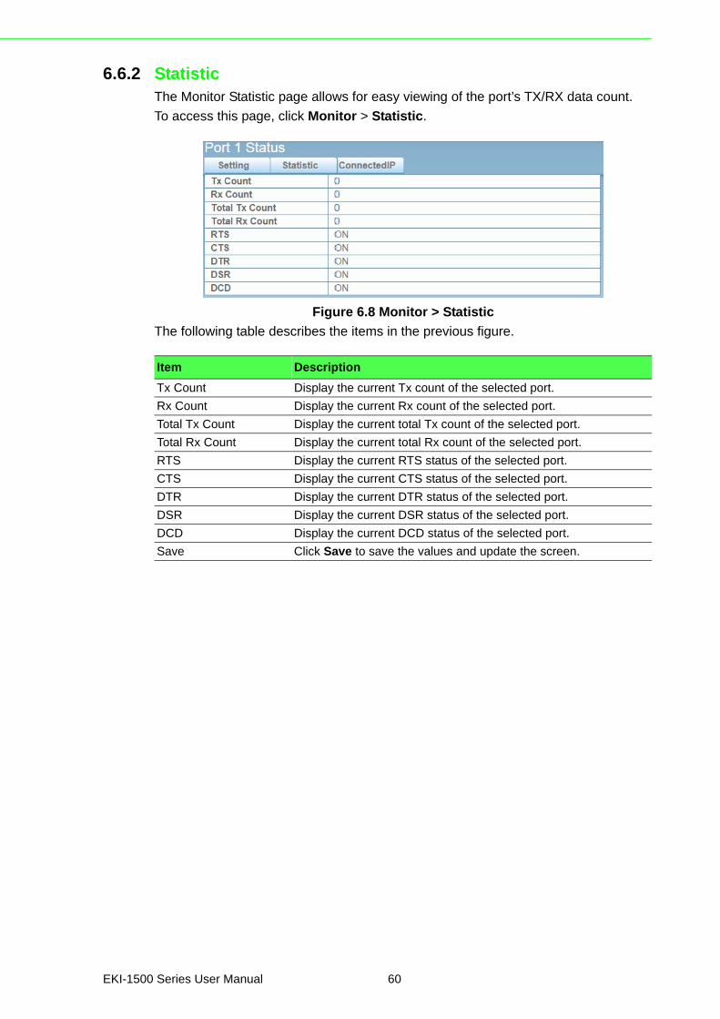
6.6.2 StatisticThe Monitor Statistic page allows for easy viewing of the port’s TX/RX data count.
To access this page, click Monitor > Statistic.
Figure 6.8 Monitor > Statistic
The following table describes the items in the previous figure.
Item Description
Tx Count Display the current Tx count of the selected port.
Rx Count Display the current Rx count of the selected port.
Total Tx Count Display the current total Tx count of the selected port.
Total Rx Count Display the current total Rx count of the selected port.
RTS Display the current RTS status of the selected port.
CTS Display the current CTS status of the selected port.
DTR Display the current DTR status of the selected port.
DSR Display the current DSR status of the selected port.
DCD Display the current DCD status of the selected port.
Save Click Save to save the values and update the screen.
EKI-1500 Series User Manual 60
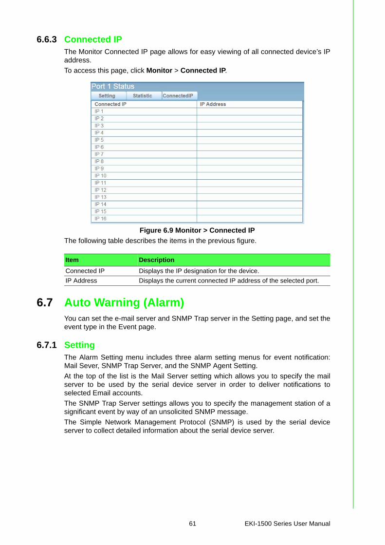
6.6.3 Connected IPThe Monitor Connected IP page allows for easy viewing of all connected device’s IPaddress.
To access this page, click Monitor > Connected IP.
Figure 6.9 Monitor > Connected IP
The following table describes the items in the previous figure.
6.7 Auto Warning (Alarm)You can set the e-mail server and SNMP Trap server in the Setting page, and set theevent type in the Event page.
6.7.1 SettingThe Alarm Setting menu includes three alarm setting menus for event notification:Mail Sever, SNMP Trap Server, and the SNMP Agent Setting.
At the top of the list is the Mail Server setting which allows you to specify the mailserver to be used by the serial device server in order to deliver notifications toselected Email accounts.
The SNMP Trap Server settings allows you to specify the management station of asignificant event by way of an unsolicited SNMP message.
The Simple Network Management Protocol (SNMP) is used by the serial deviceserver to collect detailed information about the serial device server.
Item Description
Connected IP Displays the IP designation for the device.
IP Address Displays the current connected IP address of the selected port.
61 EKI-1500 Series User Manual
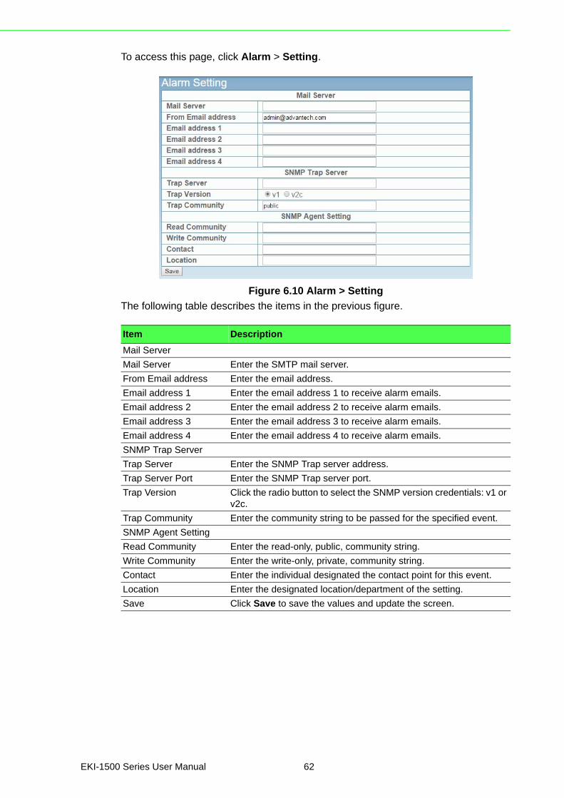
To access this page, click Alarm > Setting.
Figure 6.10 Alarm > Setting
The following table describes the items in the previous figure.
Item Description
Mail Server
Mail Server Enter the SMTP mail server.
From Email address Enter the email address.
Email address 1 Enter the email address 1 to receive alarm emails.
Email address 2 Enter the email address 2 to receive alarm emails.
Email address 3 Enter the email address 3 to receive alarm emails.
Email address 4 Enter the email address 4 to receive alarm emails.
SNMP Trap Server
Trap Server Enter the SNMP Trap server address.
Trap Server Port Enter the SNMP Trap server port.
Trap Version Click the radio button to select the SNMP version credentials: v1 or v2c.
Trap Community Enter the community string to be passed for the specified event.
SNMP Agent Setting
Read Community Enter the read-only, public, community string.
Write Community Enter the write-only, private, community string.
Contact Enter the individual designated the contact point for this event.
Location Enter the designated location/department of the setting.
Save Click Save to save the values and update the screen.
EKI-1500 Series User Manual 62
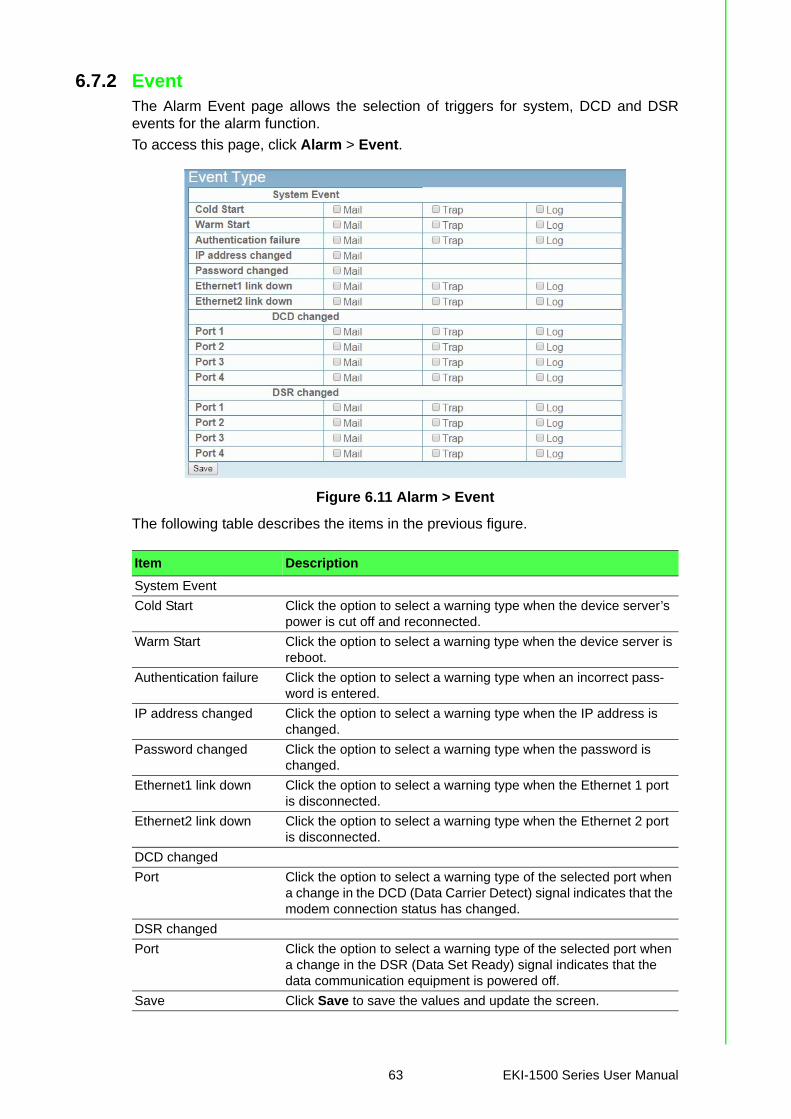
6.7.2 EventThe Alarm Event page allows the selection of triggers for system, DCD and DSRevents for the alarm function.
To access this page, click Alarm > Event.
Figure 6.11 Alarm > Event
The following table describes the items in the previous figure.
Item Description
System Event
Cold Start Click the option to select a warning type when the device server’s power is cut off and reconnected.
Warm Start Click the option to select a warning type when the device server is reboot.
Authentication failure Click the option to select a warning type when an incorrect pass-word is entered.
IP address changed Click the option to select a warning type when the IP address is changed.
Password changed Click the option to select a warning type when the password is changed.
Ethernet1 link down Click the option to select a warning type when the Ethernet 1 port is disconnected.
Ethernet2 link down Click the option to select a warning type when the Ethernet 2 port is disconnected.
DCD changed
Port Click the option to select a warning type of the selected port when a change in the DCD (Data Carrier Detect) signal indicates that the modem connection status has changed.
DSR changed
Port Click the option to select a warning type of the selected port when a change in the DSR (Data Set Ready) signal indicates that the data communication equipment is powered off.
Save Click Save to save the values and update the screen.
63 EKI-1500 Series User Manual
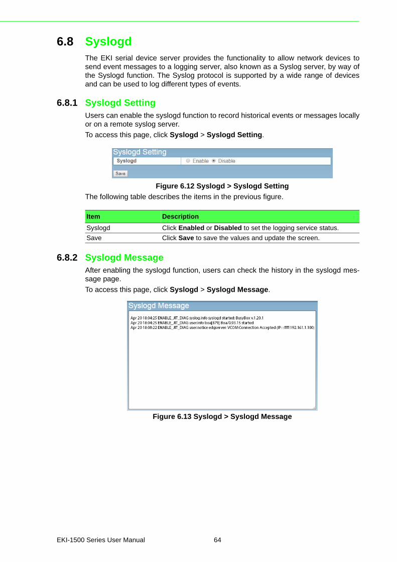
6.8 SyslogdThe EKI serial device server provides the functionality to allow network devices tosend event messages to a logging server, also known as a Syslog server, by way ofthe Syslogd function. The Syslog protocol is supported by a wide range of devicesand can be used to log different types of events.
6.8.1 Syslogd SettingUsers can enable the syslogd function to record historical events or messages locallyor on a remote syslog server.
To access this page, click Syslogd > Syslogd Setting.
Figure 6.12 Syslogd > Syslogd Setting
The following table describes the items in the previous figure.
6.8.2 Syslogd MessageAfter enabling the syslogd function, users can check the history in the syslogd mes-sage page.
To access this page, click Syslogd > Syslogd Message.
Figure 6.13 Syslogd > Syslogd Message
Item Description
Syslogd Click Enabled or Disabled to set the logging service status.
Save Click Save to save the values and update the screen.
EKI-1500 Series User Manual 64
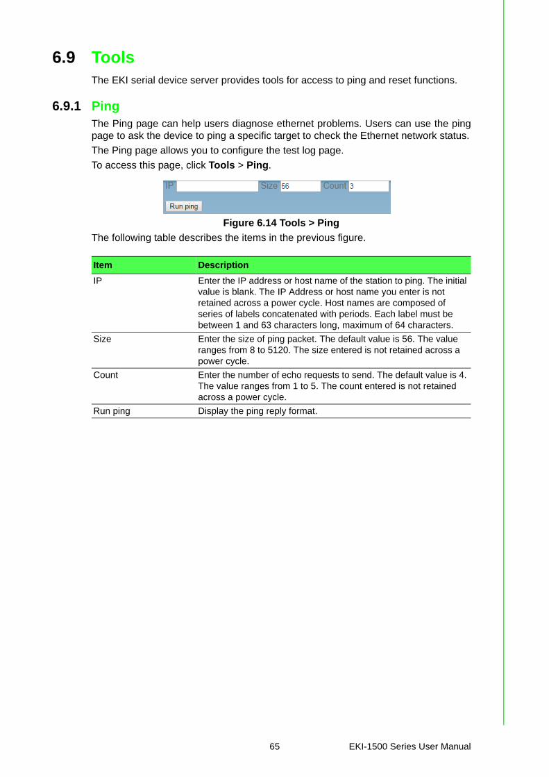
6.9 ToolsThe EKI serial device server provides tools for access to ping and reset functions.
6.9.1 PingThe Ping page can help users diagnose ethernet problems. Users can use the pingpage to ask the device to ping a specific target to check the Ethernet network status.
The Ping page allows you to configure the test log page.
To access this page, click Tools > Ping.
Figure 6.14 Tools > Ping
The following table describes the items in the previous figure.
Item Description
IP Enter the IP address or host name of the station to ping. The initial value is blank. The IP Address or host name you enter is not retained across a power cycle. Host names are composed of series of labels concatenated with periods. Each label must be between 1 and 63 characters long, maximum of 64 characters.
Size Enter the size of ping packet. The default value is 56. The value ranges from 8 to 5120. The size entered is not retained across a power cycle.
Count Enter the number of echo requests to send. The default value is 4. The value ranges from 1 to 5. The count entered is not retained across a power cycle.
Run ping Display the ping reply format.
65 EKI-1500 Series User Manual
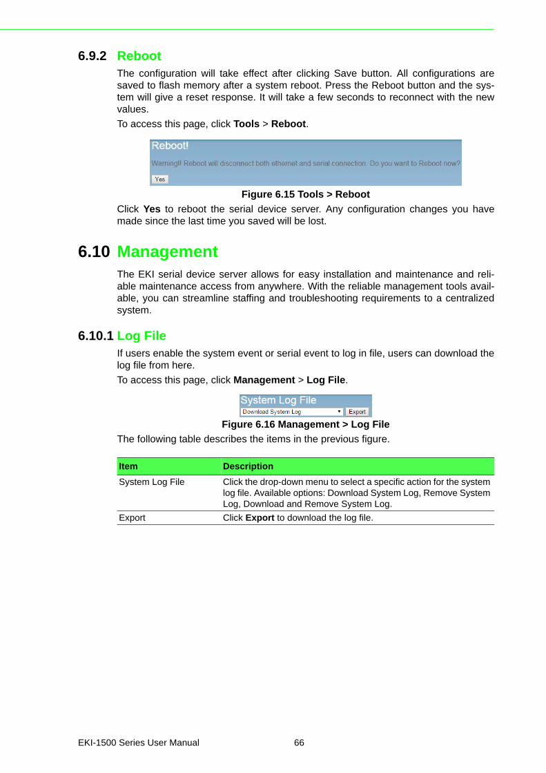
6.9.2 RebootThe configuration will take effect after clicking Save button. All configurations aresaved to flash memory after a system reboot. Press the Reboot button and the sys-tem will give a reset response. It will take a few seconds to reconnect with the newvalues.
To access this page, click Tools > Reboot.
Figure 6.15 Tools > Reboot
Click Yes to reboot the serial device server. Any configuration changes you havemade since the last time you saved will be lost.
6.10 ManagementThe EKI serial device server allows for easy installation and maintenance and reli-able maintenance access from anywhere. With the reliable management tools avail-able, you can streamline staffing and troubleshooting requirements to a centralizedsystem.
6.10.1 Log FileIf users enable the system event or serial event to log in file, users can download thelog file from here.
To access this page, click Management > Log File.
Figure 6.16 Management > Log File
The following table describes the items in the previous figure.
Item Description
System Log File Click the drop-down menu to select a specific action for the system log file. Available options: Download System Log, Remove System Log, Download and Remove System Log.
Export Click Export to download the log file.
EKI-1500 Series User Manual 66

6.10.2 Change PasswordThe Change Password function allows you to easily update your current passwordfrom a single menu.
To access this page, click Management > Change Password.
Figure 6.17 Management > Change Password
The following table describes the items in the previous figure.
If you have set a password through the configuration utility or Telnet or serial console,when you access the web configuration, you need to key in the password. It is notnecessary to enter the user name in the dialog.
If you want to disable the password protection, change the password to default optionNone (leave the new password column blank). Be sure to press the Save button andreboot the serial device server to make the change effective.
6.10.3 Export Device SettingsExport the server configuration settings to a .conf file.
To access this page, click Management > Export.
Figure 6.18 Management > Export
Click Export to export the serial device server settings.
6.10.4 Import Device SettingsImport the server configuration settings to a .conf file.
To access this page, click Management > Import.
Figure 6.19 Management > Import
The following table describes the items in the previous figure.
Item Description
New password Enter the character set for the define password type.
New password again Retype the password entry to confirm the profile password.
Save Click Save to save the values and update the screen.
Item Description
Choose File Click Choose File to select the configuration file.
Submit Click Submit to backup the settings.
67 EKI-1500 Series User Manual

Chapter 7
7Telnet/Serial Console Configuration
7.1 OverviewThe purpose of the Console Configuration is to help you manage your device in con-sole mode. One of the main functions of the console mode is to change the web con-figuration login password. You can use terminal software like Hyper Terminal, Telixand other related terminal software.
7.2 Telnet Console
7.2.1 Create a new connectionYou can create a new Telnet connection and assign a connection name for the con-sole configuration.
Figure 7.1 Creating a Telnet Connection
69 EKI-1500 Series User Manual
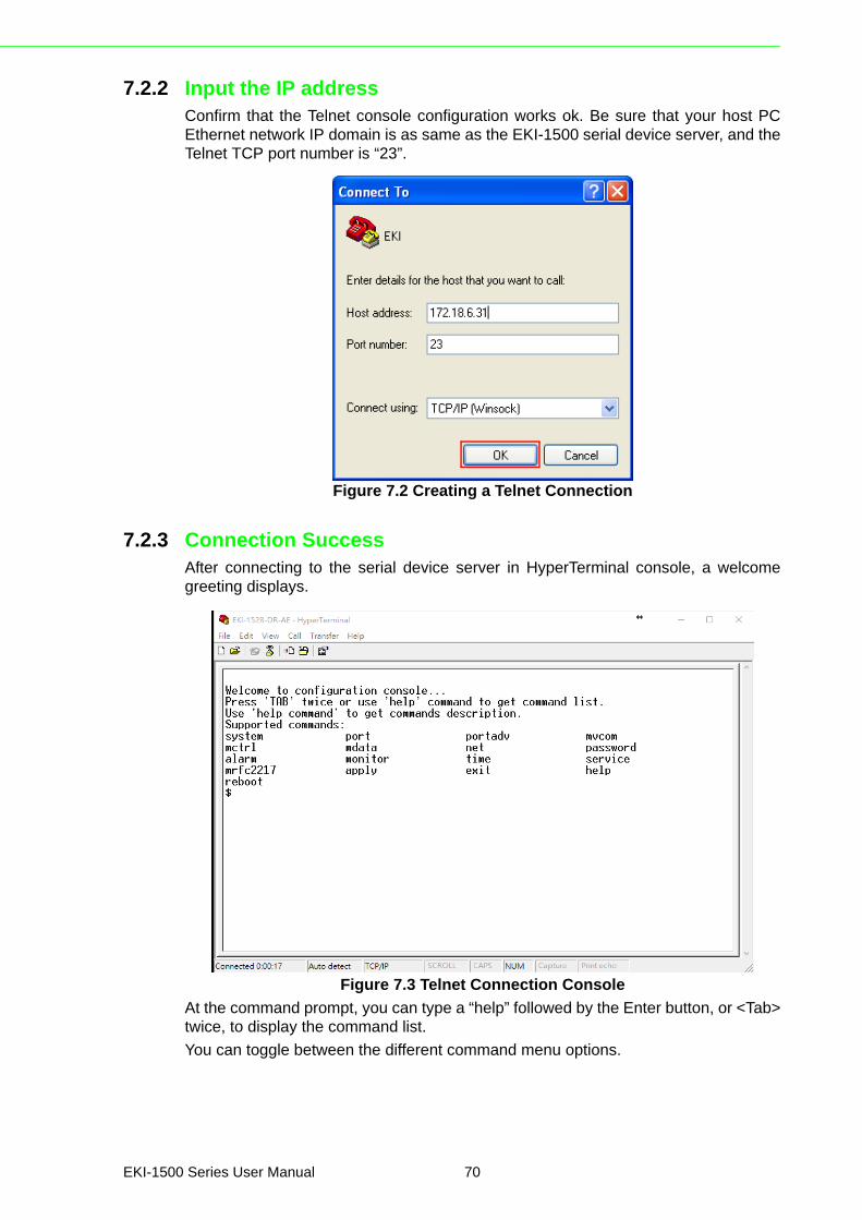
7.2.2 Input the IP addressConfirm that the Telnet console configuration works ok. Be sure that your host PCEthernet network IP domain is as same as the EKI-1500 serial device server, and theTelnet TCP port number is “23”.
Figure 7.2 Creating a Telnet Connection
7.2.3 Connection SuccessAfter connecting to the serial device server in HyperTerminal console, a welcomegreeting displays.
Figure 7.3 Telnet Connection Console
At the command prompt, you can type a “help” followed by the Enter button, or <Tab>twice, to display the command list.
You can toggle between the different command menu options.
EKI-1500 Series User Manual 70

7.3 Command List
7.3.1 systemUsage: system
Show current device status and informations.
Usage: system name [Maximum length 31 bytes]
Set current device name.
Usage: system desc [Maximum length 127 bytes]
Set current device description.
7.3.2 portUsage: port [nn|all]
Show port status and informations.
Usage: port [nn] desc [Maximum length 127 bytes]
Set serial port description.
Usage: port [nn|all] type [232|422|485] flow []
Set serial port type and flow control.
– flow 0:None.– flow 1:XOn/XOff.– flow 2:RTS/CTS.– flow 3:DTR/DSR.
Usage: port [nn|all] baud [50-921600] parity [] data [5-8] stop [1|1.5|2]
Set serial baud rate, parity and numbers of data bits, numbers of stop bits.
Acceptable baud: 50, 75, 110, 150, 300, 600, 1200, 1800, 2400, 4800, 7200,9600, 14400, 19200, 38400, 57600, 115200, 230400, 460800, and 921600
– parity n: None Parity.– parity e: Even Parity.– parity o: Odd Parity.– parity m: Mark Parity.
Command Function Description
system Show or configure the system information
port Show or configure the serial ports information
portadv Show or configure the serial ports advanced settings
mvcom Show or configure the serial ports in Virtual COM mode
mctrl Show or configure the serial ports in Control mode (USDG)
mdata Show or configure the serial ports in Data mode (USDG)
net Show or configure the Ethernet ports settings
password Set or change the password
alarm Show or configure the auto warning functions including mail alarm and SNMP alarm
monitor Monitor the serial ports status
mrfc2217 Show all port modes and mode information.
apply Write settings to the flash memory and reboot the system immediately
exit Terminate the shell session
help Display command list help information
reboot Write settings and reboot the system immediately.
71 EKI-1500 Series User Manual

– parity s: Space Parity.Usage: port [nn|all] mode [vcom|ctrl|data]
Set serial port as virtual COM port or control mode or data mode.
7.3.3 portadv$ help portadv
Show port advanced setting.
Usage: portadv [nn|all] delayT []
Set delay time(ms).
Usage: portadv [nn|all] ignorepurge [TRUE|FALSE] dischato [TRUE|FALSE] dismulti-con [TRUE|FALSE]
Enable or disable the feature of ignore purge,
Disable character timeout detection, and disable multiple connection.
Usage: portadv [nn|all] databuf []
Set databuffer threshold.
Usage: portadv [nn|all] timeout [] rtl [] ttl [] fcl [] fch []
Set port timeout, and set portrtl, portttl, portfcl, portfch.
Usage: portadv [nn|all] fifosize [size|null]
Set port Writed size of FIFO, null for disable
Usage: portadv [nn|all] rts []
Set port RTS status.
– value 0: None Setting.– value 1: Setting power on.– value 2: Setting accept on.– value 4: Setting transmission on.
Usage: portadv [nn|all] dtr []
Set port DTR status.
– value 0: None Setting.– value 1: Setting power on.– value 2: Setting accept on.– value 4: Setting transmission on.
7.3.4 mvcomUsage: mvcom
Show all port mode and mode informations.
Usage: mvcom [nn|all]
Set port [nn|all] as virtual COM port mode.
Usage: mvcom [nn|all] idleto []
Set host idle timeout(s).
Usage: mvcom [nn|all] respto [] framebk []
Set response timeout(ms) and frame break(ms).
Usage: mvcom [nn|all] bysize []
Usage: mvcom [nn|all] bytime []
Usage: mvcom [nn|all] bychar [NULL|]
Set datapackage as size (bytes) or time (ms) and character (HEX).
– value 0: None Setting.
EKI-1500 Series User Manual 72

7.3.5 mctrlUsage: mctrl
Show port mode and mode informations.
Usage: mctrl [nn|all]
Set port [nn|all] as control mode.
Usage: mctrl [nn|all] idleto [] tcpp [] atp [] guardt [] hangchr []
Set data idle timeout(s) data listen port command listen port guard time(ms)hangup character.
7.3.6 mdataUsage: mdata
Show port mode and mode informations.
Usage: mdata [nn|all]
Set port [nn|all] as data mode.
Usage: mdata [nn|all] protocol [TCP|UDP]
Set transmit protocol as TCP or UDP.
Usage: mdata [nn|all] idleto [] lsport [] atport []
Set data idle timeout(s) listen port and AT command port.
Usage: mdata [nn|all] respto [] framebk []
Set response timeout(ms) and frame break(ms).
Usage: mdata [nn|all] bysize [] bytime [] bychar [NULL|] bychartimeout [ON|OFF]
Set datapackage as size (bytes) or time (ms) or character (HEX) and character-timeout.
– value 0: None Setting.Usage: mdata [nn|all] autopeerip [ON|OFF]
Set auto connect to peer ip as on or off.
Usage: mdata [nn|all] peernum [1-16] peer [d.d.d.d:d] ...
Set peer IP address and port for receive data.
7.3.7 netUsage: net [1|2]
Show device network status and informations.
Usage: net [1|2] mode [static|dhcp|bootp|all]
Set network operating mode.
Usage: net [1|2] ip [d.d.d.d] netmask [d.d.d.d] gw [d.d.d.d]
Set IP address and subnet mask and gateway.
Usage: net [1|2] dns [auto|specific]
Enable/Disable DNS.
Usage: net [1|2] dns1 [d.d.d.d]
Set network DNS1.
Usage: net [1|2] dns2 [d.d.d.d]
Set network DNS2.
Usage: net [1|2] to [d]
Set network timeout.
73 EKI-1500 Series User Manual

7.3.8 passwordUsage: password
Display two different Usage.
Usage: password new [1-31 characters]
Set new password.
Usage: password old [**...] new [1-31 characters]
Confirm the old password and set new password.
7.3.9 alarmUsage: alarm
Show current alarm informations.
Usage: alarm mail server [null|address] from [null|address] to1 [null|address] to2[null|address] to3 [null|address] to4 [null|address]
Set current mail server configuration.
Usage: alarm trap server [null|address] ver [1|2] community [null|name]
Set current trap server configuration.
Usage: alarm agent rcommunity [null|name] wcommunity [null|name] contact[null|name] location [null|name]
Set current snmp agent configuration.
Usage: alarm event mail [cstart] [wstart] [auth] [ip] [passwd] [eth1] [eth2]
Set current mail event configuration.
Usage: alarm event trap [cstart] [wstart] [auth] [eth1] [eth2]
Set current trap event configuration.
Usage: alarm port [1|2|..] dcd [none|mail|trap|all] dsr [none|mail|trap|all]
Set current port alarm configuration.
7.3.10 monitorUsage: monitor port [1|2|..] setting
Monitor COM port setting.
Usage: monitor port [1|2|..] statistic
Monitor COM port statistic data.
Usage: monitor port [1|2|..] ip
Monitor connected IP.
7.3.11 timeUsage: time
Show current time informations.
Usage: time [YYYYMMDDhhmmss]
Set current time configuration.
Usage: time ntp [timeserver]
Set current time server configuration.
EKI-1500 Series User Manual 74

7.3.12 serviceUsage: service telnet [enable|disable]
Enable/Disable telnet function.
Usage: service snmp [enable|disable]
Enable/Disable SNMP function.
7.3.13 mrfc2217Usage: mrfc2217
Show all port mode and mode informations.
Usage: mrfc2217 [nn|all]
Set port [nn|all] as RFC2217 mode.
Usage: mrfc2217 [nn|all] idleto [] lsport []
Set host idle timeout(s) and listen port.
7.3.14 applyUsage: apply
Save the settings to flash and reboot right now.
7.3.15 exitUsage: exit
Terminate shell session.
7.3.16 helpUsage: help [cmd]
Display help information of command cmd.
7.3.17 rebootUsage: reboot
Write settings and reboot the system immediately.
75 EKI-1500 Series User Manual

Appendix A
ATCP and UDP Port Numbers
77 EKI-1500 Series User Manual
A.1 List of Known TCP and UDP Port Numbers
Port Protocol Service
5048 (TCP/UDP) Configuration Utility
5058 (TCP/UDP) Configuration Utility
5202 (TDP) VCOM/RVCOM
9999 (TDP) Firmware Download
22 (TDP) SSH
23 (TDP) Telnet
25 (TDP) SMTP (Mail Client)
53 (TCP/UDP) DNS
67 (UDP) BOOTP Server/DHCP
68 (UDP) BOOTP Client/DHCP
80 (TDP) Web Interface/HTTP
123 (TDP) NTP
161 (TDP) SNMP
162 (TCP/UDP) SNMP Trap
443 (TDP) HTTPS
502 (TDP) Modbus/TCP (Default)
514 (TDP) Syslog
546 (TCP/UDP) DHCPv6 Client
547 (TCP/UDP) DHCPv6 Server

www.advantech.comPlease verify specifications before quoting. This guide is intended for referencepurposes only.All product specifications are subject to change without notice.No part of this publication may be reproduced in any form or by any means,electronic, photocopying, recording or otherwise, without prior written permis-sion of the publisher.All brand and product names are trademarks or registered trademarks of theirrespective companies.© Advantech Co., Ltd. 2016