
effects of fibre architecture on deformation during preform manufacture
10
EFFECTS OF FIBRE ARCHITECTURE ON DEFORMATION DURING PREFORM MANUFACTURE A.C. Long, B.J. Souter, F. Robitaille, and C.D. Rudd School of Mechanical, Materials, Manufacturing Engineering & Management, Division of Mechanical Engineering, University of Nottingham, University Park, Nottingham NG7 2RD, UK SUMMARY: Simulations of fabric deformation during preform manufacture are usually based on a kinematic mapping of the fibres onto the component. Whilst this approach can anticipate excessive deformation, it takes no account of the effect of fabric construction on subsequent forming characteristics. The aim of this study is to establish a relationship between fibre architecture and formability, and to incorporate this within an enhanced draping simulation. The approach utilises a geometric model for woven or warp-knitted fabrics, which forms the basis of a mechanical model for fabric deformation. The model is then used to determine the shear strain energy required to produce a particular draped fibre pattern. This is implemented within an iterative procedure to determine the draped pattern resulting in minimum strain energy. The results compare favourably with experiments for hemispherical preforms, where initial fabric construction is shown to have a significant effect on the resulting fibre orientations. KEYWORDS: textile preforms, fabric shear, drape modelling, liquid composite moulding INTRODUCTION Preforms for use in liquid moulding processes can be produced via forming or draping of reinforcement fabrics. Reinforcements are available in a number of forms, including woven and warp-knitted (stitch-bonded) fabric structures. There are now a large number of suppliers, each providing a range of fabrics with different characteristics. Materials selection, therefore, can be a difficult and time-consuming process if based on trial and error. Over the last ten years, a number of studies have been carried out into fabric deformation characteristics and deformation modelling. This has led to the development of test methods for fabric formability, usually based on either simple shearing or uniaxial extension along the bias [1-3]. Over a similar period, a number of fabric deformation models or drape simulations have been developed [eg. 4,5]. These simulations are usually based on a kinematic mapping of the fibres onto the surface of the preforming tool, and can be used to anticipate changes in fibre
Transcript of effects of fibre architecture on deformation during preform manufacture

EFFECTS OF FIBRE ARCHITECTURE ONDEFORMATION DURING PREFORM
MANUFACTURE
A.C. Long, B.J. Souter, F. Robitaille, and C.D. Rudd
School of Mechanical, Materials, Manufacturing Engineering & Management,Division of Mechanical Engineering, University of Nottingham,
University Park, Nottingham NG7 2RD, UK
SUMMARY: Simulations of fabric deformation during preform manufacture are usuallybased on a kinematic mapping of the fibres onto the component. Whilst this approach cananticipate excessive deformation, it takes no account of the effect of fabric construction onsubsequent forming characteristics. The aim of this study is to establish a relationshipbetween fibre architecture and formability, and to incorporate this within an enhanced drapingsimulation. The approach utilises a geometric model for woven or warp-knitted fabrics,which forms the basis of a mechanical model for fabric deformation. The model is then usedto determine the shear strain energy required to produce a particular draped fibre pattern. Thisis implemented within an iterative procedure to determine the draped pattern resulting inminimum strain energy. The results compare favourably with experiments for hemisphericalpreforms, where initial fabric construction is shown to have a significant effect on theresulting fibre orientations.
KEYWORDS: textile preforms, fabric shear, drape modelling, liquid composite moulding
INTRODUCTION
Preforms for use in liquid moulding processes can be produced via forming or draping ofreinforcement fabrics. Reinforcements are available in a number of forms, including wovenand warp-knitted (stitch-bonded) fabric structures. There are now a large number of suppliers,each providing a range of fabrics with different characteristics. Materials selection, therefore,can be a difficult and time-consuming process if based on trial and error. Over the last tenyears, a number of studies have been carried out into fabric deformation characteristics anddeformation modelling. This has led to the development of test methods for fabricformability, usually based on either simple shearing or uniaxial extension along the bias [1-3].Over a similar period, a number of fabric deformation models or drape simulations have beendeveloped [eg. 4,5]. These simulations are usually based on a kinematic mapping of the fibresonto the surface of the preforming tool, and can be used to anticipate changes in fibre

orientations and volume fractions, from which subsequent properties such as permeability andelastic constants may be inferred.
Although a number of fabric drape simulations are now available, the majority of these makeno attempt to account for the differences between fabrics, other than in the specification of a“locking angle” which indicates the limit of deformation. Indeed the above mentioned workon characterisation of fabric deformation has, for the most part, taken place in isolation fromthe development of deformation simulations. The authors have shown that fabric constructioncan have a significant effect on the deformed fibre pattern, even for simple shapes such ashemispheres or disks [2]. This is particularly evident for warp-knitted fabrics, where shearforces and subsequent fabric locking angles can differ for deformation parallel andperpendicular to the stitching thread. Some potential for inclusion of fabric specific effectshas been shown in the development of finite element simulations for fabric/composite forming[eg. 6,7], but these possibilities have not been explored to date.
The objectives of this study were to investigate the possibility of incorporating aspects offabric deformation mechanics within an existing drape simulation. The intended approach isto use the traditional pin-jointed approximation within an iterative scheme based onminimization of shear strain energy. The first stage in this process was to develop a geometricmodel for fabric reinforcements, which could be used as a basis for a mechanical model offabric shear. Results from the shear model can be used to generate shear strain energy data,which can be incorporated within the iterative drape simulation. This is demonstrated for twowarp-knitted fabrics, which illustrate the effects of initial fibre architecture on the subsequentdeformed fibre pattern.
FABRIC GEOMETRIC MODEL
Before a general model for the mechanics of fabric deformation can be developed, it is firstnecessary to develop a model to describe the initial fibre architecture. This description canalso be used as a basis for the prediction of subsequent flow properties (permeability). In thissection, a single definition is proposed for the interlacing patterns of woven and warp-knittedfabrics. The definition consists of a series of vectors which describe the paths of individualtows between crossover or intersection points. Although the basis of the definition is general,additional specifications are required for woven fabrics (to define the weave pattern) andwarp-knitted fabrics (to define the stitching pattern).
Woven Fabrics
To describe the interlacing pattern for a woven material, it is first necessary to specify thenumber of levels on which the warp-wise (Li,wp) and weft-wise (Li,wt) tows are positioned (Fig.1). A standard fabric features one level in both the warp and the weft directions, whereasentering a total number of levels greater than two creates a 3D woven textile. The levels areidentified sequentially (Li), firstly for warp-wise tows and then for weft-wise tows. Thedimensions of the repeating cell are then specified by defining the number of warp-wise(RCiwp) and weft-wise (RCiwt) tows present in the unit cell along with the tow spacings.Following this, the tow type is specified for warp-wise and weft-wise tows at each level in therepeating cell. This allows fabrics to be represented which include more than one tow type(for example, a hybrid carbon/glass fabric or a quasi-unidirectional material with a lighttransverse tow). Each crossover in the repeating cell is defined within the weaving matrix

[WPi] of dimensions RCi.wp , RCi,wt . The interlacing pattern of the reinforcement is defined byentering the level identifiers (Li) of each tow from bottom to top for each crossover into thismatrix (Fig. 2).
Fig. 1: Interlacing patterns for woven materials. Fig. 2: Vectorial term wsi ( 1 , 1 ),defining the interlacing sequence.
The quantities defined above allow vectors defining the interlacing pattern to be generatedover the repeating cell by rearranging the weaving matrix [WPi] and combining with thevalues of the tow spacing. Whereas the vectors define the correct in-plane dimensions, theout-of-plane dimension (ie. fabric thickness) is defined as an integer. This is because it isdifficult to obtain an accurate measure of the tow thickness. Ultimately the intention is topredict this with a mechanical model for tow deformation.
Warp-Knitted Fabrics
Warp-knitted (stitch-bonded or non-crimp) fabrics consist of reinforcement tows held togetherby stitching threads. To specify the interlacing patterns for these textiles, the user firstspecifies the number of non-interlacing levels of tows (Li,tow), and the number of levels ofwarp-knitted threads (Li,thread) as shown in Fig. 3. Individual levels are given a unique numberfor both the non-interlaced tows (Li,w) and the warp-knitted threads (Li,d).
Single level of threads,no tows inserted
Two levels of threads,no tows inserted
Overlaps
Underlaps
Single level of threads,
on level of tows insertedSingle level of threads,
two levels of tows inserted
Fig. 3: Warp-knitted textiles: Li,thread levels of threads assembled by Li,tow levels of tows.
RC i,wp = 6 RCi,wt = 4
LevelLi = 5LevelLi = 4
LevelLi = 3LevelLi = 2LevelLi = 1
Zi
Yi
(weft)
Xi
(warp)Li,wp = 2 Li,wt = 3
Typical tow,Ci,wt = 1
Typical crossover,C i,wp = 5 ,Ci,wt = 3
Repeatingcell
Ci,wt = 1
C i,wt = RC i,wt
C i,wp = 1
Ci,wp = RC i,wp
Li = 2
Li = 1
Li = 5
Li = 4
Li = 3
Yi
(weft)
Xi
(warp)
Zi
wsi ( 1,1 ) = [ 3, 1, 4, 5, 2]
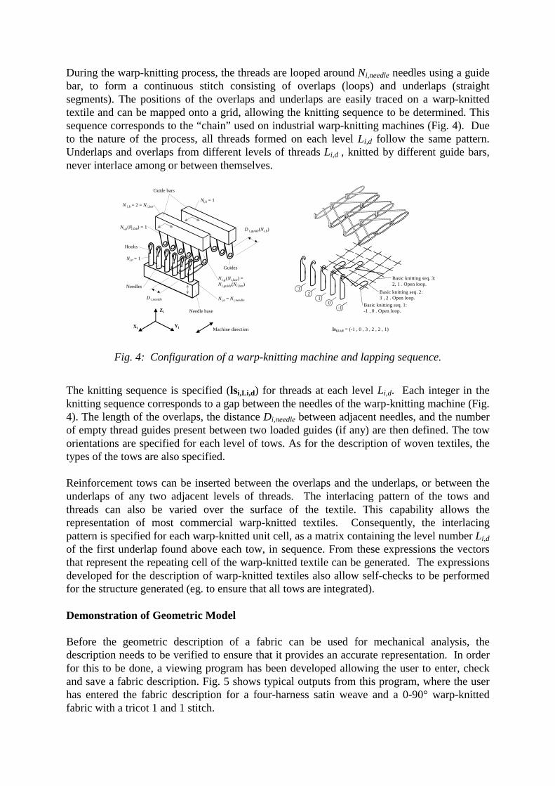
During the warp-knitting process, the threads are looped around Ni,needle needles using a guidebar, to form a continuous stitch consisting of overlaps (loops) and underlaps (straightsegments). The positions of the overlaps and underlaps are easily traced on a warp-knittedtextile and can be mapped onto a grid, allowing the knitting sequence to be determined. Thissequence corresponds to the “chain” used on industrial warp-knitting machines (Fig. 4). Dueto the nature of the process, all threads formed on each level Li,d follow the same pattern.Underlaps and overlaps from different levels of threads Li,d , knitted by different guide bars,never interlace among or between themselves.
Needle base
D i,needle
Hooks
Ni,n = 1
Ni,n = N i,needle
Needles
Guide bars
Ni,b = 1 N i,b = 2 = N i,bar
Ni,g(Ni,bar) = 1
N i,g(N i,bar ) = N i,guide(N i,bar )
Guides
D i,guide(N i,b )
Xi Yi
Zi
Machine direction
-10
12
3
Basic knitting seq. 1:-1 , 0 . Open loop.
Basic knitting seq. 2:3 , 2 . Open loop.
Basic knitting seq. 3:2, 1 . Open loop.
lsi,Li,d = (-1 , 0 , 3 , 2 , 2 , 1)
Fig. 4: Configuration of a warp-knitting machine and lapping sequence.
The knitting sequence is specified (lsi,Li,d) for threads at each level Li,d. Each integer in theknitting sequence corresponds to a gap between the needles of the warp-knitting machine (Fig.4). The length of the overlaps, the distance Di,needle between adjacent needles, and the numberof empty thread guides present between two loaded guides (if any) are then defined. The toworientations are specified for each level of tows. As for the description of woven textiles, thetypes of the tows are also specified.
Reinforcement tows can be inserted between the overlaps and the underlaps, or between theunderlaps of any two adjacent levels of threads. The interlacing pattern of the tows andthreads can also be varied over the surface of the textile. This capability allows therepresentation of most commercial warp-knitted textiles. Consequently, the interlacingpattern is specified for each warp-knitted unit cell, as a matrix containing the level number Li,dof the first underlap found above each tow, in sequence. From these expressions the vectorsthat represent the repeating cell of the warp-knitted textile can be generated. The expressionsdeveloped for the description of warp-knitted textiles also allow self-checks to be performedfor the structure generated (eg. to ensure that all tows are integrated).
Demonstration of Geometric Model
Before the geometric description of a fabric can be used for mechanical analysis, thedescription needs to be verified to ensure that it provides an accurate representation. In orderfor this to be done, a viewing program has been developed allowing the user to enter, checkand save a fabric description. Fig. 5 shows typical outputs from this program, where the userhas entered the fabric description for a four-harness satin weave and a 0-90° warp-knittedfabric with a tricot 1 and 1 stitch.

Fig. 5: Graphical representations of fabric geometric model –four-harness satin weave (left) and 0/90° tricot stitched fabric (right).
MECHANICAL MODEL FOR FABRIC SHEAR
To determine the effects of fibre architecture on fabric formability, a mechanical model forfabric deformation is under development. This will utilise the information provided by thefabric geometric model to determine the shear force and ultimately the limit of deformationfor an arbitrary textile structure. This has been implemented for in-plane shearing of a plainweave fabric, as described below. It is intended that a similar approach will be adopted forother fibre architectures, although it is recognised that an alternative model may be requiredfor warp-knitted textiles to account for the tensile properties of the stitching thread.
For a general woven textile, three deformation modes are considered: tow flexion, inter-towrotational friction at the crossovers, and tow compaction. These three modes essentially occurin a sequential manner as in-plane shear deformation is imposed. A series of assumptionswere used in the development of the model for plain weaves:
• Tow paths are lenticular;• Even contact is achieved at tow crossovers;• Tow width (Tw) varies during shearing, whereas tow spacing (Ts) is constant;• Fabric thickness remains constant during shearing.
Many geometrical descriptions of a plain-weave unit cell have been proposed, includingcircular, sinusoidal and elliptical tow cross-sections or paths. However experimentalobservations support the assumption of a lenticular path. The assumption of constant fabricthickness during shearing is based on experimental measurements by McBride [3].
As observed by Kawabata [8], after an initial (often negligible) contribution from the towflexural rigidity, the main resistance to deformation comes from the friction at tow crossovers.Neglecting the flexural rigidity, the shear force can be obtained by considering torque at eachcrossover:
effccrr RFT ××= µ (1)
where µcr is the coefficient of friction at the crossover (assumed to be 0.3), and Fc is thecontact force. Reff is the effective radius of rotation through which the torque acts:
∫=A
eff rdAA
R 1 (2)

where A is the tow contact area, which is assumed to be a parallelogram formed by theoutlines of the contacting tows. Calculation of the effective radius relies on accuratelypredicting the tow width. From simple geometric considerations, the tow width would beexpected to obey the following relationship with shear angle, θ :
( ) Lisw
Liww
TTTT
θθθθθ
>⋅=≤=
cos 0 (3)
where Tw0 is the initial tow width, and the angle at which adjacent tows come into contact isgiven by:
= −
s
wLi T
T 01cosθ (4)
This relationship was verified by performing a number of shear tests using a parallelogramfixture and measuring the change in tow width using a digital camera. The results agreedextremely well with the predicted values.
Prior to lateral contact (ie. when θ ≤ θLi), the tow contact force arises from the pre-tensionwithin the fabric. Once the tows come into contact an additional force arises from inter-towcompaction. In this model the compaction model developed by Cai and Gutowski [9] foraligned fibre bundles is used. The fibre bundle stress can be obtained from:
( )2111
11
bbb
bb FFF
Fe−⋅
⋅=σ (5)
where eb is the bundle strain and F11, Fbb and Fb1 are compliance terms, which are functions ofthe fibre modulus and instantaneous fibre volume fraction of the bundle. The fibre bundlestress is integrated over the tow contact area and substituted into Eqn. 1 to obtain the torque ata tow crossover. The shear force is then calculated from the sum of the torque contributionsfor each crossover.
Typical predictions appear in Fig. 6for two plain weave fabrics, usingthe parameters given in Table 1. Theexperimental results were obtainedusing a parallelogram shearingfixture mounted in a mechanicaltesting machine. Each test wascarried out at 100mm/min. Asshown in the figure, the predictionsare in good agreement with theexperimental results. However itshould be noted that not all of thevariables in Table 1 could bemeasured directly. Both the fabricpre-tension and thickness werechosen to obtain reasonable agreement with the experimental results. To obtain consistentresults, pre-tension is applied to the fabric using a clamping frame prior to mounting within
Fig. 6: Predicted and experimental shear forcecurves for plain weave fabrics.
0
50
100
150
200
250
300
0 10 20 30 40 50 60 70 80
Shear angle (°)
Shea
r For
ce (N
)
600 Plain Weave150 Plain Weave600 Predicted150 Predicted

the shearing fixture. However, it is thought that some degree of relaxation occurs prior totesting. This problem should be eliminated by improving the experimental procedure. Thefabric thickness may be determined once a suitable model for the deformation of an individualtow has been developed.
Table 1: Fabric data for mechanical fabric shear model600 g/m2
plain weave150 g/m2
plain weaveTow width (mm) 3.1 1.2Tow spacing (mm) 4.0 2.0Linear density (Tex) 1190 150Thickness (mm) 2 0.6Pre-Tension (N) 100 50
Despite the above reservations, the model produces encouraging results. In particular, itseems capable of anticipating the rapid increase in shear force which occurs immediately priorto fabric wrinkling (indicative of the locking angle). The model is presently being developedto predict the shearing behaviour of other textile architectures.
ENERGY APPROACH TO DEFORMATION MODELLING
The conventional approach to drape simulation for reinforcement fabrics is to model thematerial as a pin-jointed net. A unique draped pattern can be obtained by specifying twointersecting fibre paths, referred to as generators, on the surface of the preforming tool, fromwhich the remaining fibres can be positioned using a geometric mapping. This approachworks well for symmetric shapes draped with balanced fabrics, but is less satisfactory for non-symmetric shapes or for fabrics which have a preferential direction for shearing. This isdemonstrated in Fig. 7, which shows the fibre patterns for hemispherical preforms producedusing two warp-knitted fabrics from Tech Textiles. Samples were produced using matchedtooling mounted in a mechanical testing machine, with fibres marked prior to forming toillustrate the subsequent deformation. Despite the component symmetry, two very differentnon-symmetric fibre patterns were obtained. Both fabrics were restricted in quadrants shearedparallel to the stitching thread, with the effect most pronounced for the chain stitch.
Fig. 7: Hemispherical preforms produced using ±45o warp-knitted fabrics –left: E-BXhd 936 (tricot 1 and 1 stitch), right: E-BX 318 (chain stitch).
A more sophisticated approach to fabric deformation modelling involves a sequentialsimulation using the finite element method. This can overcome some of the above problemsat the expense of increased computation time. An alternative approach is therefore proposed,
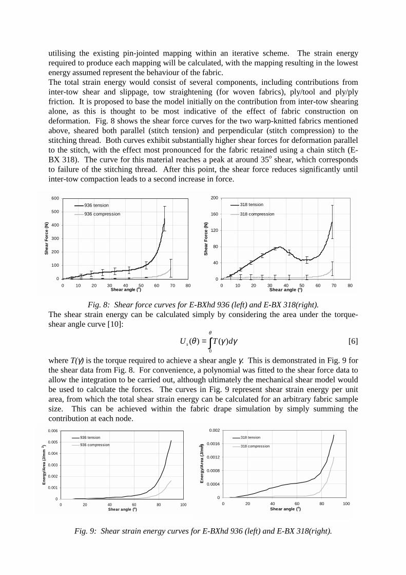
utilising the existing pin-jointed mapping within an iterative scheme. The strain energyrequired to produce each mapping will be calculated, with the mapping resulting in the lowestenergy assumed represent the behaviour of the fabric.The total strain energy would consist of several components, including contributions frominter-tow shear and slippage, tow straightening (for woven fabrics), ply/tool and ply/plyfriction. It is proposed to base the model initially on the contribution from inter-tow shearingalone, as this is thought to be most indicative of the effect of fabric construction ondeformation. Fig. 8 shows the shear force curves for the two warp-knitted fabrics mentionedabove, sheared both parallel (stitch tension) and perpendicular (stitch compression) to thestitching thread. Both curves exhibit substantially higher shear forces for deformation parallelto the stitch, with the effect most pronounced for the fabric retained using a chain stitch (E-BX 318). The curve for this material reaches a peak at around 35o shear, which correspondsto failure of the stitching thread. After this point, the shear force reduces significantly untilinter-tow compaction leads to a second increase in force.
Fig. 8: Shear force curves for E-BXhd 936 (left) and E-BX 318(right).The shear strain energy can be calculated simply by considering the area under the torque-shear angle curve [10]:
∫=θ
γγθ0
)()( dTUs [6]
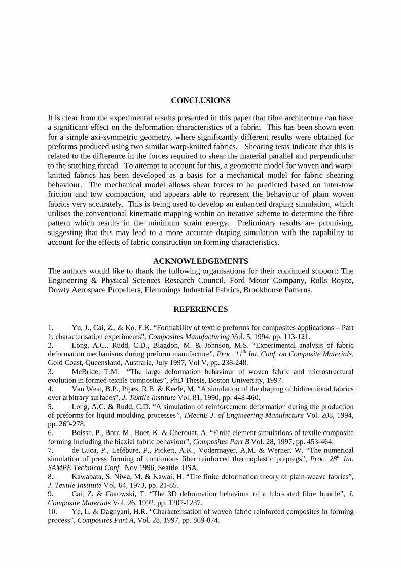
where T(γ) is the torque required to achieve a shear angle γ. This is demonstrated in Fig. 9 forthe shear data from Fig. 8. For convenience, a polynomial was fitted to the shear force data toallow the integration to be carried out, although ultimately the mechanical shear model wouldbe used to calculate the forces. The curves in Fig. 9 represent shear strain energy per unitarea, from which the total shear strain energy can be calculated for an arbitrary fabric samplesize. This can be achieved within the fabric drape simulation by simply summing thecontribution at each node.
Fig. 9: Shear strain energy curves for E-BXhd 936 (left) and E-BX 318(right).
0
100
200
300
400
500
600
0 10 20 30 40 50 60 70 80Shear angle (o)
Shea
r For
ce (N
)
936 tension
936 compression
0
40
80
120
160
200
0 10 20 30 40 50 60 70 80Shear angle (°)
Shea
r For
ce (N
)318 tension
318 compression
0
0.001
0.002
0.003
0.004
0.005
0.006
0 20 40 60 80 100Shear angle (o)
Ener
gy/A
rea
(J/m
m2 )
936 tension
936 compression
0
0.0004
0.0008
0.0012
0.0016
0.002
0 20 40 60 80 100Shear angle (o)
Ene
rgy/
Are
a (J
/mm2 )
318 tension
318 compression

A simple way to determine themapping resulting in the minimumenergy is to develop an iterativescheme based on the two generatorfibre paths. The approach would theninvolve simply finding the twointersecting paths which resulted inthe lowest energy mapping. From theexperimental results shown in Fig. 7,one possible approach for thehemispherical mould would be tosimply vary the angle of intersectionof these fibres. Fig. 10 shows a graphof total shear strain energy against thisintersection angle. It is clear that anoptimum value exists for both fabrics (approximately 75o for E-BXhd 936 and 60o for E-BX318). Fig. 11 shows the predicted fibre pattern for each fabric using these angles.Comparison with Fig. 7 shows that the predicted optimum mappings correspond reasonablywell with the experimental results. Clearly there is some room for improvement, as the actualfibre paths which correspond to the generator fibres (marked as bold lines on Fig. 7) arecurved rather than straight. Nevertheless this approach appears to show some potential. Thenext stage will be to develop a more sophisticated iterative scheme which will allow the initialpaths to be determined more accurately. The model will then be tested for a wide range offabrics and for more challenging, non-symmetric geometries.
Fig. 11: Comparison of deformed fibre patterns –optimum for E-BXhd 936 (left), optimum for E-BXhd 318 (right).
Fig. 10: Total shear strain energy versusgenerator fibre intersection angle.
1.5
1.75
2
2.25
2.5
2.75
3
3.25
50 55 60 65 70 75 80 85 90
Generator Inter-Fibre Angle (o)
Shea
r Stra
in E
nerg
y (J
)
E-BXhd 936E-BX 318
CONCLUSIONS
It is clear from the experimental results presented in this paper that fibre architecture can havea significant effect on the deformation characteristics of a fabric. This has been shown evenfor a simple axi-symmetric geometry, where significantly different results were obtained forpreforms produced using two similar warp-knitted fabrics. Shearing tests indicate that this isrelated to the difference in the forces required to shear the material parallel and perpendicularto the stitching thread. To attempt to account for this, a geometric model for woven and warp-knitted fabrics has been developed as a basis for a mechanical model for fabric shearingbehaviour. The mechanical model allows shear forces to be predicted based on inter-towfriction and tow compaction, and appears able to represent the behaviour of plain wovenfabrics very accurately. This is being used to develop an enhanced draping simulation, whichutilises the conventional kinematic mapping within an iterative scheme to determine the fibrepattern which results in the minimum strain energy. Preliminary results are promising,suggesting that this may lead to a more accurate draping simulation with the capability toaccount for the effects of fabric construction on forming characteristics.
ACKNOWLEDGEMENTSThe authors would like to thank the following organisations for their continued support: TheEngineering & Physical Sciences Research Council, Ford Motor Company, Rolls Royce,Dowty Aerospace Propellers, Flemmings Industrial Fabrics, Brookhouse Patterns.
REFERENCES
1. Yu, J., Cai, Z., & Ko, F.K. “Formability of textile preforms for composites applications – Part1: characterisation experiments”, Composites Manufacturing Vol. 5, 1994, pp. 113-121.2. Long, A.C., Rudd, C.D., Blagdon, M. & Johnson, M.S. “Experimental analysis of fabricdeformation mechanisms during preform manufacture”, Proc. 11th Int. Conf. on Composite Materials,Gold Coast, Queensland, Australia, July 1997, Vol V, pp. 238-248.3. McBride, T.M. “The large deformation behaviour of woven fabric and microstructuralevolution in formed textile composites”, PhD Thesis, Boston University, 1997.4. Van West, B.P., Pipes, R.B. & Keefe, M. “A simulation of the draping of bidirectional fabricsover arbitrary surfaces”, J. Textile Institute Vol. 81, 1990, pp. 448-460.5. Long, A.C. & Rudd, C.D. “A simulation of reinforcement deformation during the productionof preforms for liquid moulding processes”, IMechE J. of Engineering Manufacture Vol. 208, 1994,pp. 269-278.6. Boisse, P., Borr, M., Buet, K. & Cherouat, A. “Finite element simulations of textile compositeforming including the biaxial fabric behaviour”, Composites Part B Vol. 28, 1997, pp. 453-464.7. de Luca, P., Lefébure, P., Pickett, A.K., Vodermayer, A.M. & Werner, W. “The numericalsimulation of press forming of continuous fiber reinforced thermoplastic prepregs”, Proc. 28th Int.SAMPE Technical Conf., Nov 1996, Seattle, USA.8. Kawabata, S. Niwa, M. & Kawai, H. “The finite deformation theory of plain-weave fabrics”,J. Textile Institute Vol. 64, 1973, pp. 21-85.9. Cai, Z. & Gutowski, T. “The 3D deformation behaviour of a lubricated fibre bundle”, J.Composite Materials Vol. 26, 1992, pp. 1207-1237.10. Ye, L. & Daghyani, H.R. “Characterisation of woven fabric reinforced composites in formingprocess”, Composites Part A, Vol. 28, 1997, pp. 869-874.