Effective Notch Stress Method for Fatigue Evaluation of ...089-092)-12-013.pdf · Effective Notch...
4
IJR International Journal of Railway Vol. 5, No. 2 / June 2012, pp. 89-92 Vol. 5, No. 2 / June 2012 - 89 - The Korean Society for Railway Effective Notch Stress Method for Fatigue Evaluation of Welded Joints in a Steel Bridge Deck Sim, Hyoung-Bo † Abstract Effective notch stress, as an approach to evaluate the local stress at a notch (weld toe or root), is defined as the total stress assuming linear-elastic material behavior. This method can be effectively used to evaluate the fatigue perfor- mance of welded joints. In this study, finite element analysis results using the effective notch stress method were cor- related with fatigue test results of rib-to-deck welded joints in a steel orthotropic bridge deck. Effective notch stress approach provided a good correlation with the crack pattern observed in the full-scale fatigue test. A higher effective notch stress at the critical weld toe than at the weld root was consistent with the dominant crack pattern observed at the weld toe during testing. The effective notch stress at the toe on the deck plate was about 80% higher than that on the rib; no cracks at the weld toe on the rib in the testing were observed. Maximum effective notch stress at the weld root occurred on the upper side of the root notch, which indicates that cracks are more likely to propagate into the deck plate, not into the weld metal. This is also consistent with the observed crack pattern in which the crack from the root propagated upward into the deck plate. No such crack pattern, propagating into the weld metal, was observed in the testing. Key words : Effective notch stress, Fatigue crack, Finite element analysis, Welded joint, Steel bridge 1. Introduction Effective (or imaginary) notch stress, as an approach to evaluate the local stress at a notch (weld toe or root), is defined as the total stress (for example, Von-Mises Stress) assuming linear-elastic material behavior. This approach has been extensively discussed by Interna- tional Institute of Welding (IIW 2007), and it is docu- mented in the IIW Recommendations (Miki 2006). The actual weld contour is replaced by an effective one in order to consider the statistical nature and scatter of weld shape parameters, as well as the non-linear mate- rial behavior at the notch. In this study, finite element analysis results using the effective notch stress method were correlated with fatigue test results to investigate its effectiveness in fatigue evaluation of welded joints in a steel orthotropic bridge deck. 2. Fatigue Test 2.1 Orthotropic bridge deck An orthotropic steel deck, which is widely used for long- and medium-span bridges, typically consists of thin steel plate stiffened by a series of closely spaced longitudinal ribs and transverse floor beams supporting the deck plate (see Fig. 1). † Corresponding author: Korea Railroad Research Institute E-mail : [email protected] Fig. 1 Typical configuration of orthotropic deck (Troitsky 1987)
Transcript of Effective Notch Stress Method for Fatigue Evaluation of ...089-092)-12-013.pdf · Effective Notch...

IJR International Journal of Railway
Vol. 5, No. 2 / June 2012, pp. 89-92
Vol. 5, No. 2 / June 2012 − 89 −
The Korean Society for Railway
Effective Notch Stress Method for Fatigue Evaluation of
Welded Joints in a Steel Bridge Deck
Sim, Hyoung-Bo†
Abstract
Effective notch stress, as an approach to evaluate the local stress at a notch (weld toe or root), is defined as the total
stress assuming linear-elastic material behavior. This method can be effectively used to evaluate the fatigue perfor-
mance of welded joints. In this study, finite element analysis results using the effective notch stress method were cor-
related with fatigue test results of rib-to-deck welded joints in a steel orthotropic bridge deck. Effective notch stress
approach provided a good correlation with the crack pattern observed in the full-scale fatigue test. A higher effective
notch stress at the critical weld toe than at the weld root was consistent with the dominant crack pattern observed at
the weld toe during testing. The effective notch stress at the toe on the deck plate was about 80% higher than that on
the rib; no cracks at the weld toe on the rib in the testing were observed. Maximum effective notch stress at the weld
root occurred on the upper side of the root notch, which indicates that cracks are more likely to propagate into the
deck plate, not into the weld metal. This is also consistent with the observed crack pattern in which the crack from the
root propagated upward into the deck plate. No such crack pattern, propagating into the weld metal, was observed in
the testing.
Key words : Effective notch stress, Fatigue crack, Finite element analysis, Welded joint, Steel bridge
1. Introduction
Effective (or imaginary) notch stress, as an approach
to evaluate the local stress at a notch (weld toe or root),
is defined as the total stress (for example, Von-Mises
Stress) assuming linear-elastic material behavior. This
approach has been extensively discussed by Interna-
tional Institute of Welding (IIW 2007), and it is docu-
mented in the IIW Recommendations (Miki 2006). The
actual weld contour is replaced by an effective one in
order to consider the statistical nature and scatter of
weld shape parameters, as well as the non-linear mate-
rial behavior at the notch. In this study, finite element
analysis results using the effective notch stress method
were correlated with fatigue test results to investigate its
effectiveness in fatigue evaluation of welded joints in a
steel orthotropic bridge deck.
2. Fatigue Test
2.1 Orthotropic bridge deck
An orthotropic steel deck, which is widely used for long-
and medium-span bridges, typically consists of thin steel plate
stiffened by a series of closely spaced longitudinal ribs and
transverse floor beams supporting the deck plate (see Fig. 1).
† Corresponding author: Korea Railroad Research Institute
E-mail : [email protected]
Fig. 1 Typical configuration of orthotropic deck
(Troitsky 1987)
− 90 −
Sim, Hyoung-Bo / IJR, 5(2), 89-92, 2012
Despite light weight and excellent structural characteristics
of this deck system, orthotropic steel deck bridges have expe-
rienced a variety of fatigue problems. In particular, rib-to-
deck partial-joint-penetration (PJP) welded joints are prone to
fatigue cracking because they are subjected to local second-
ary deformations (out-of-plane transverse bending moment)
from the directly applied wheel loads, as shown in Fig. 2.
2.2 Test condition
Recently, six full-scale orthotropic deck specimens (10
m long and 3 m wide) were tested at the University of Cal-
ifornia, San Diego to evaluate the fatigue performance at
rib-to-deck welded joint (Sim and Uang 2007). ASTM
A709 Grade 345 steel was used for the specimens. Each
deck panel was composed of a 16-mm-thick deck plate
and four 8-mm-thick ribs. Fig. 3 shows the test setup with
cross-sectional view of the test specimen. An actuator was
centered on each span, and the diaphragms of each speci-
men were supported by concrete blocks. The specimen
was loaded using hydraulic actuators at midspan. The
applied loads from the two actuators were out of phase to
simulate the effect of a truck passage. The loads from each
actuator at midspan were uniformly distributed through a
spreader beam to the loading pads. The testing was con-
ducted in a load-controlled mode with a loading fre-
quency ranging from 4 to 6 Hz.
2.3 Summary of test results
Fatigue test results showed that six cracks at rib-to-deck
welded joint developed from the weld toe outside the
closed rib, and only one crack developed at the weld root
inside the closed rib. Based on the loading pattern applied
and the limited database, it was indicated that the rib-to-
Fig. 2 Local deformation at rib-to-deck welded joint
Fig. 3 Fatigue test setup
Fig. 4 Fatigue cracks observed during testing
Effective Notch Stress Method for Fatigue Evaluation of Welded Joints in a Steel Bridge Deck
− 91 −
deck PJP welds are more vulnerable to crack initiation
from the weld toe than from the weld root.
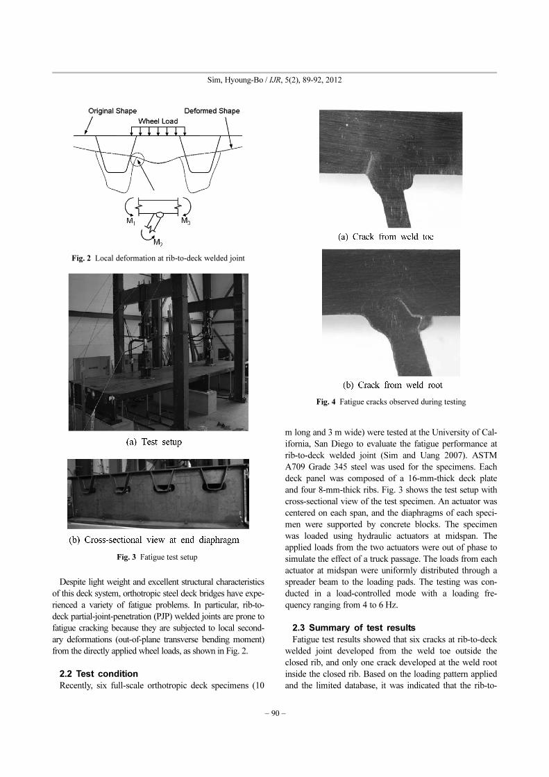
Fig. 4 shows the crack patterns observed at the rib-to-deck
welded joints by magnetic particle inspection after comple-
tion of testing. All seven cracks were developed within the
deck plate and not within the rib wall, which indicates that
the fatigue cracks at rib-to-deck joints appear to be more
critical within the deck plate than within the rib wall.
3. Finite Element Analysis
3.1 Model
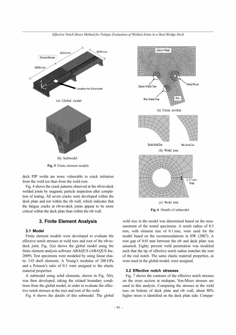
Finite element models were developed to evaluate the
effective notch stresses at weld toes and root of the rib-to-
deck joint. Fig. 5(a) shows the global model using the
finite element analysis software ABAQUS (ABAQUS Inc.
2009). Test specimens were modeled by using linear elas-
tic 3-D shell elements. A Young’s modulus of 200 GPa
and a Poisson’s ratio of 0.3 were assigned to the elastic
material properties.
A submodel using solid elements, shown in Fig. 5(b),
was then developed, taking the related boundary condi-
tions from the global model, in order to evaluate the effec-
tive notch stresses at the toes and root of the weld.
Fig. 6 shows the details of this submodel. The global
weld size in the model was determined based on the mea-
surement of the tested specimens. A notch radius of 0.5
mm, with element size of 0.1 mm, were used for the
model based on the recommendations in IIW (2007). A
root gap of 0.01 mm between the rib and deck plate was
assumed. Eighty percent weld penetration was modeled
such that the tip of effective notch radius matches the root
of the real notch. The same elastic material properties, as
were used in the global model, were assigned.
3.2 Effective notch stresses
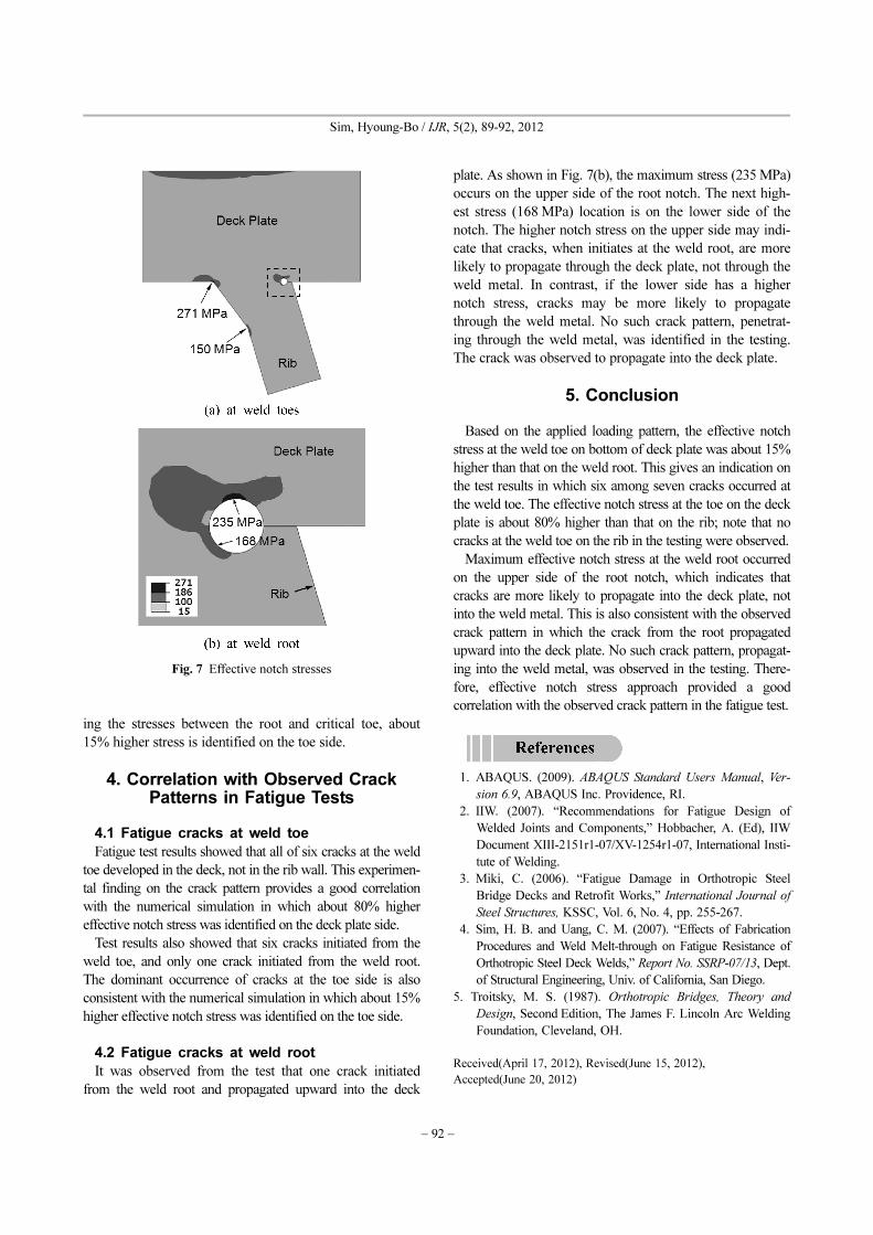
Fig. 7 shows the contours of the effective notch stresses
on the cross section at midspan; Von-Mises stresses are
used in this analysis. Comparing the stresses at the weld
toes on bottom of deck plate and rib wall, about 80%
higher stress is identified on the deck plate side. Compar-
Fig. 5 Finite element models
Fig. 6 Details of submodel
− 92 −
Sim, Hyoung-Bo / IJR, 5(2), 89-92, 2012
ing the stresses between the root and critical toe, about
15% higher stress is identified on the toe side.
4. Correlation with Observed Crack Patterns in Fatigue Tests
4.1 Fatigue cracks at weld toe
Fatigue test results showed that all of six cracks at the weld
toe developed in the deck, not in the rib wall. This experimen-
tal finding on the crack pattern provides a good correlation
with the numerical simulation in which about 80% higher
effective notch stress was identified on the deck plate side.
Test results also showed that six cracks initiated from the
weld toe, and only one crack initiated from the weld root.
The dominant occurrence of cracks at the toe side is also
consistent with the numerical simulation in which about 15%
higher effective notch stress was identified on the toe side.
4.2 Fatigue cracks at weld root
It was observed from the test that one crack initiated
from the weld root and propagated upward into the deck
plate. As shown in Fig. 7(b), the maximum stress (235 MPa)
occurs on the upper side of the root notch. The next high-
est stress (168 MPa) location is on the lower side of the
notch. The higher notch stress on the upper side may indi-
cate that cracks, when initiates at the weld root, are more
likely to propagate through the deck plate, not through the
weld metal. In contrast, if the lower side has a higher
notch stress, cracks may be more likely to propagate
through the weld metal. No such crack pattern, penetrat-
ing through the weld metal, was identified in the testing.
The crack was observed to propagate into the deck plate.
5. Conclusion
Based on the applied loading pattern, the effective notch
stress at the weld toe on bottom of deck plate was about 15%
higher than that on the weld root. This gives an indication on
the test results in which six among seven cracks occurred at
the weld toe. The effective notch stress at the toe on the deck
plate is about 80% higher than that on the rib; note that no
cracks at the weld toe on the rib in the testing were observed.
Maximum effective notch stress at the weld root occurred
on the upper side of the root notch, which indicates that
cracks are more likely to propagate into the deck plate, not
into the weld metal. This is also consistent with the observed
crack pattern in which the crack from the root propagated
upward into the deck plate. No such crack pattern, propagat-
ing into the weld metal, was observed in the testing. There-
fore, effective notch stress approach provided a good
correlation with the observed crack pattern in the fatigue test.
1. ABAQUS. (2009). ABAQUS Standard Users Manual, Ver-
sion 6.9, ABAQUS Inc. Providence, RI.
2. IIW. (2007). “Recommendations for Fatigue Design of
Welded Joints and Components,” Hobbacher, A. (Ed), IIW
Document XIII-2151r1-07/XV-1254r1-07, International Insti-
tute of Welding.
3. Miki, C. (2006). “Fatigue Damage in Orthotropic Steel
Bridge Decks and Retrofit Works,” International Journal of
Steel Structures, KSSC, Vol. 6, No. 4, pp. 255-267.
4. Sim, H. B. and Uang, C. M. (2007). “Effects of Fabrication
Procedures and Weld Melt-through on Fatigue Resistance of
Orthotropic Steel Deck Welds,” Report No. SSRP-07/13, Dept.
of Structural Engineering, Univ. of California, San Diego.
5. Troitsky, M. S. (1987). Orthotropic Bridges, Theory and
Design, Second Edition, The James F. Lincoln Arc Welding
Foundation, Cleveland, OH.
Received(April 17, 2012), Revised(June 15, 2012),
Accepted(June 20, 2012)
Fig. 7 Effective notch stresses