![AMM-2019-4 · ternal tensile stresses and notch sensitivity of Ti6Al4V. Fatigue properties of Ti6Al4V have been widely investigated [8,9], and it was reported that the fatigue fracture](https://static.fdocuments.net/doc/165x107/5f06c17e7e708231d4199329/amm-2019-4-ternal-tensile-stresses-and-notch-sensitivity-of-ti6al4v-fatigue-properties.jpg)
IMPACT OF NOTCH GEOMETRY ON THE FATIGUE LIFE OF …
7
International Research Journal of Engineering and Technology (IRJET) e-ISSN: 2395-0056 Volume: 07 Issue: 11 | Nov 2020 www.irjet.net p-ISSN: 2395-0072 © 2020, IRJET | Impact Factor value: 7.529 | ISO 9001:2008 Certified Journal | Page 1389 IMPACT OF NOTCH GEOMETRY ON THE FATIGUE LIFE OF AISI 316L AUSTENITIC STAINLESS STEEL Mohd Ishaq 1 , J.Jagadesh Kumar 2 1 Final Year M.Tech Student, Dept. of Mechanical engineering, VJIT College, Telangana, India 2 Associate Professor, Dept. of Mech, Vidya Jyothi Institute of Technology, Telangana, India ---------------------------------------------------------------------***---------------------------------------------------------------------- Abstract - An AISI316L is an austenitic stainless steel improved with an addition of 2.5% Molybdenum to provide improved corrosion resistance to AISI 316L stainless steel. 316L stainless steel has improved pitting corrosion resistance and has excellent resistance to Sulphates, phosphates and other salts. 316L has highly superior and better resistance than standard 18/8 types to sea water, reducing acids and solution of chlorides, bromides and iodies. AISI 316L steels are widely used as marine application such as boat rails and hardware, facades of buildings, pharmaceutical and bio-processing, Dairy and Food, brewery and other beverage industries due to its high corrosion resistance, and heat resistance provide the excellent fabric ability and formability. In this project work, the Impact of notch geometry on the fatigue life of AISI 316L austenitic stainless steel is investigated experimentally on Nano Universal Testing Machine. The AISI 316L steel round bar samples were subjected to total Strain loading under different parameters. The characterization of base material was done in through chemical composition, microstructure, tensile test and hardness. The LCF tests were conducted on material to obtain fatigue life of AISI 316L austenitic stainless steel material. The microstructure, micro-damage and fractured surfaces were examined with optical microscopy. Key Words: AISI 316LAustenitic Stainless steel, Fatigue Life, Low cycle fatigue (LCF), Nano Universal testing machine. 1. INTRODUCTION 1.1 Problem Statement The Machines is a mechanical structure that uses power to apply forces to control the movement and other components which we use in daily life are often subjected to several forces encircled. The stresses and strains developed are sometimes periodic depending on the direction of forces. Though the magnitude of strain is below their yield limit but they cause failure when they are applied several times periodically. When a material is subjected to repeated cycles of stress or strain, failure occurs by leading to fracture at some weak points and this type of a failure is termed as Fatigue. Fatigue deformation is caused by the synchronous action of cyclic stress, tensile stress, and plastic strain. The plastic strain occurring from cyclic stress initiates the crack, the tensile stress promotes the crack growth (propagation). Cautious computation of strain depict that microscopic plastic strains could exist at low levels of stress where the strain might otherwise appear to be totally elastic. Though compressive stresses do not cause fatigue failure, compressive loads may induce local tensile stresses. It is necessary to take some measures to increase fatigue life of components either by changing the geometry of the components or reducing the resistance opposed near the material. Geometry change is not a solution, especially due to some constraints. Thereby fatigue life of component is increased by decreasing the strains in the material. Various ways such as heat treatment, coating, etc.., can increase fatigue life of material but under the research we can carry forward in consideration of strains. In Naval and Marine AISI 316L Stainless Steel material mainly used because it has good property of corrosion resistance and excellent weight to strength ratio. The aim of the project “Impact of notch geometry on the fatigue life of grade 316-L austenitic stainless steel” is to improve the wear resistance with increase in fatigue life. The project concentrates more on the Fatigue and strain amplitude aspects as it is already evident from existing literature that wear resistance and corrosion would be improved and test can be carried out under Total strain controlled condition for AISI 316L Stainless Steel. 1.2. Objectives of the Work: Main objectives of this investigation and plans of work can be briefly summarized as: To know the impact of notch geometry on the fatigue life of AISI 316L austenitic stainless steel: This part consists of (a) Micro structural characterization of the material, (b) Determination of hardness, (c) Tensile properties. To study the low cycle fatigue behavior of AISI 316L austenitic stainless steel at different strain amplitude: The major experiments to fulfill this investigation related to low cyclic fatigue tests under various constant strain amplitudes in order to get the response of stress (cyclic hardening or softening) due to cyclic loading. To examine the effect of pre-fatigue cycling on the tensile properties of the selected steel: The tests in this part include
Transcript of IMPACT OF NOTCH GEOMETRY ON THE FATIGUE LIFE OF …

International Research Journal of Engineering and Technology (IRJET) e-ISSN: 2395-0056
Volume: 07 Issue: 11 | Nov 2020 www.irjet.net p-ISSN: 2395-0072
© 2020, IRJET | Impact Factor value: 7.529 | ISO 9001:2008 Certified Journal | Page 1389
IMPACT OF NOTCH GEOMETRY ON THE FATIGUE LIFE OF AISI 316L
AUSTENITIC STAINLESS STEEL
Mohd Ishaq1, J.Jagadesh Kumar2
1Final Year M.Tech Student, Dept. of Mechanical engineering, VJIT College, Telangana, India 2Associate Professor, Dept. of Mech, Vidya Jyothi Institute of Technology, Telangana, India
---------------------------------------------------------------------***----------------------------------------------------------------------Abstract - An AISI316L is an austenitic stainless steel improved with an addition of 2.5% Molybdenum to provide improved corrosion resistance to AISI 316L stainless steel. 316L stainless steel has improved pitting corrosion resistance and has excellent resistance to Sulphates, phosphates and other salts. 316L has highly superior and better resistance than standard 18/8 types to sea water, reducing acids and solution of chlorides, bromides and iodies. AISI 316L steels are widely used as marine application such as boat rails and hardware, facades of buildings, pharmaceutical and bio-processing, Dairy and Food, brewery and other beverage industries due to its high corrosion resistance, and heat resistance provide the excellent fabric ability and formability. In this project work, the Impact of notch geometry on the fatigue life of AISI 316L austenitic stainless steel is investigated experimentally on Nano Universal Testing Machine. The AISI 316L steel round bar samples were subjected to total Strain loading under different parameters. The characterization of base material was done in through chemical composition, microstructure, tensile test and hardness. The LCF tests were conducted on material to obtain fatigue life of AISI 316L austenitic stainless steel material. The microstructure, micro-damage and fractured surfaces were examined with optical microscopy.
Key Words: AISI 316LAustenitic Stainless steel, Fatigue Life, Low cycle fatigue (LCF), Nano Universal testing machine.
1. INTRODUCTION
1.1 Problem Statement
The Machines is a mechanical structure that uses power to apply forces to control the movement and other components which we use in daily life are often subjected to several forces encircled. The stresses and strains developed are sometimes periodic depending on the direction of forces. Though the magnitude of strain is below their yield limit but they cause failure when they are applied several times periodically. When a material is subjected to repeated cycles of stress or strain, failure occurs by leading to fracture at some weak points and this type of a failure is termed as Fatigue. Fatigue deformation is caused by the synchronous action of cyclic stress, tensile stress, and plastic strain. The plastic strain occurring from cyclic stress initiates the crack, the tensile stress promotes the crack growth (propagation).
Cautious computation of strain depict that microscopic plastic strains could exist at low levels of stress where the strain might otherwise appear to be totally elastic. Though compressive stresses do not cause fatigue failure, compressive loads may induce local tensile stresses. It is necessary to take some measures to increase fatigue life of components either by changing the geometry of the components or reducing the resistance opposed near the material. Geometry change is not a solution, especially due to some constraints. Thereby fatigue life of component is increased by decreasing the strains in the material. Various ways such as heat treatment, coating, etc.., can increase fatigue life of material but under the research we can carry forward in consideration of strains.
In Naval and Marine AISI 316L Stainless Steel material mainly used because it has good property of corrosion resistance and excellent weight to strength ratio. The aim of the project “Impact of notch geometry on the fatigue life of grade 316-L austenitic stainless steel” is to improve the wear resistance with increase in fatigue life. The project concentrates more on the Fatigue and strain amplitude aspects as it is already evident from existing literature that wear resistance and corrosion would be improved and test can be carried out under Total strain controlled condition for AISI 316L Stainless Steel.
1.2. Objectives of the Work:
Main objectives of this investigation and plans of work can be briefly summarized as:
To know the impact of notch geometry on the fatigue life of AISI 316L austenitic stainless steel: This part consists of
(a) Micro structural characterization of the material,
(b) Determination of hardness, (c) Tensile properties.
To study the low cycle fatigue behavior of AISI 316L austenitic stainless steel at different strain amplitude: The major experiments to fulfill this investigation related to low cyclic fatigue tests under various constant strain amplitudes in order to get the response of stress (cyclic hardening or softening) due to cyclic loading.
To examine the effect of pre-fatigue cycling on the tensile properties of the selected steel: The tests in this part include

International Research Journal of Engineering and Technology (IRJET) e-ISSN: 2395-0056
Volume: 07 Issue: 11 | Nov 2020 www.irjet.net p-ISSN: 2395-0072
© 2020, IRJET | Impact Factor value: 7.529 | ISO 9001:2008 Certified Journal | Page 1390
conducting tensile tests on specimens subjected to previous cyclic loading.
To assess the extent of phase transformation due to deformation: This part consists of micro structural characterization of the deformed material using SEM profile analysis.
2. Material Selection
Austenitic stainless steel is a specific type of stainless steel alloy. Stainless steels may be classified by their crystalline structures. For the work Austenitic stainless steel of AISI 316L stainless steel material was selected for this investigation. This material is commercially purein nature. It was available in the form of rod with diameter 16 mm. The material is bought from the available market as raw material and is allowed to undergo for machining process on CNC lathe so as to perform the fatigue test on suitable geometry. Below in the picture 5.2 it displays the Austenitic Stainless Steel specimens machined from the CNC lathe and made it in its final form for fatigue testing. Firstly, the specimen is modeled in the software called Creo 3.0 with the geometric dimensions as shown in the picture below. The picture shows the un notch specimen
ANSYS 18.0 software and applying various loads results in to fatigue condition. By analyzing the loads, the below pictures can explain the life approached by un notch and notched specimen. The below pictures are placed from the ANSYS 18.0 software. Once the model is ready tensile test is also performed to have its ultimate tensile strength along with Brinell hardness is also known to apply the form of Rossel – Fatemi. Results for tensile and Brinell hardness is observed from the below pictures. Indentation on the raw material of AISI 316L is shown with the dots which were indented and a machined specimen when allowed with some load results in the breakage gives tensile strength.
Figure2.1 Tensile Test Specimen & Figure 2.2 Hardness test on Raw AISI 316L
Table: 2.1 Material and Number of Specimens
Material Type Number of specimens
Austenitic Stainless Steel AISI 316L Specimens
Round solid bars
20
2.1 Properties of AISI 316 L
Physical Properties:
The following table shows the physical properties of AISI 316L stainless steel.
Table 2.2 Physical Properties of AISI 316L Stainless Steel
Properties Metric
Density 8.027g/cm3
Melting point 1440oC
2.2 Mechanical Properties:
The mechanical properties of AISI 316L stainless steel are displayed in the following table.
Table 2.3 Mechanical Properties of AISI 316L Stainless Steel
Mechanical Properties Metric
Yield Point,MPa 300
Tensile strength, MPa 719
Bulk modulus, GPa 166
Modulus of Elasticity, GPa
193
Poisson’s ratio 0.25-0.30
Strength at break, MPa
425
Elongation at break, mm
47.40
Hardness (Brinell) 184
Figure 2.3 Specimen geometry used for fatigue tests.
2.3 Control and Data Acquisition System
The displacement of the flat specimen is measured by control and data acquisition system during each load cycle, controls the strain in the specimen and adjusts the load applied by the loading device so specimen is tested with

International Research Journal of Engineering and Technology (IRJET) e-ISSN: 2395-0056
Volume: 07 Issue: 11 | Nov 2020 www.irjet.net p-ISSN: 2395-0072
© 2020, IRJET | Impact Factor value: 7.529 | ISO 9001:2008 Certified Journal | Page 1391
constant level of load on each cycle. In addition, the control and data acquisition system records load cycles, applied loads, measuring strain and computing and recording the maximum tensile stress and maximum tensile strain at load cycle intervals specified by the user.
2.3.1 Technical details of Fatigue machine
• 6 kHz digital servo control
• 23-bit data acquisition
• Stroke/load/Strain/COD
• 0-100 Hz cycling
• MS-Office compatible
• USB Interface
• Single phase 220V supply
Capacity 25KN
Figure 2.4 Nano Servo Hydraulic Fatigue Testing Machine.
3. RESULTS & DISCUSSIONS
3.1 Experimental Result’s
The life cycles range between 1≤ N ≤ 103, it is classified as Low Cycle Fatigue and if it ranges N≥103 then it is considered as High Cycle Fatigue. Let us have an open study on Strain life method. To have a strain life prediction and to estimate the fatigue life of a specimen we have a method called as ϵN method. ϵN method is a fatigue design method to estimate the number of cycles to initiate a fatigue crack using a value of strain amplitude under cyclic loading. The Fatigue test method uses strain range instead of stress range to have a fatigue life of material. Generally, it is used to model the low cycle fatigue when plastic strain range ∆ϵρand
Elastic range ∆ϵe at critical are under seismic loads. This method is useful for estimation of crack initiation and propagation life of material. Through ϵN method, the strain range ∆ϵ at critical location and its initiation life (N) is related by “Coffin- Mansons” expression introduced in 1910, given below.
Strain Amplitude = Elastic range + Plastic range
Where,
= Total strain amplitude
= Elastic strain amplitude
= Plastic strain amplitude
= Fatigue ductility coefficient
c = Fatigue ductility exponent
= Fatigue strength coefficient
b = Fatigue strength exponent
E = Modulus of elasticity
For the above Coffin - Mansons Expression there is an approach by applying Murlidhar - Mansons methods called as modified universal slopes method where we come across Fatigue strength coefficient and fatigue ductility coefficient.
From Murlidhar – Mansons method (Modified Universal Slopes Method), we can have a form for Fatigue Strength Coefficient as
Where,
Su is Ultimate tensile Strength and is Fatigue strength
coefficient
From RoessleFatemi method for steels of Brinell hardness between 150 to 700 the Fatigue ductility Coefficient can be calculated using below relation.
International Research Journal of Engineering and Technology (IRJET) e-ISSN: 2395-0056
Volume: 07 Issue: 11 | Nov 2020 www.irjet.net p-ISSN: 2395-0072
© 2020, IRJET | Impact Factor value: 7.529 | ISO 9001:2008 Certified Journal | Page 1392
Therefore,
Now let us combine Fatigue strength coefficient and Fatigue Ductility coefficient in above form of Coffin-Mansons equation.
The final form is represented as below.
Figure 3.1. Broken specimens with their life cycles
GRAPH RESULT OF SPECIMEN
Graph -3.1.No notch Specimen
- 1
Graph – 3.2. No notch specimen -
2
Graph – 3.3. Specimen -1 notch
120º
Graph – 3.4. Specimen -6 notch 120º
Graph –3.5. Specimen – 8
notch 120º
Graph – 3.6 Specimen -2 notch
240º
Graph – 3.7. Specimen- 4 notch 240º
Graph –3.8. Specimen -9 notch 240º
Graph – 3.9.Specimen –
3notch360º
Graph – 3.10.Specimen – 5 notch 360º
Graph –3.11.Specimen – 7 notch 360º
Table 3.2. Taguchi Orthogonal Array (L9) without Notches
Specimen with no Notch Fatigue Life (cycles) Trial 1 Trial 2 Average 6204 6911 6558
Table 3.3. AISI 316L Taguchi Orthogonal Array (L9)
S.No
Width (mm)
Depth (mm)
Notch Central Angle
Trial 1
Trial 2
Average
1 1 0.5 120° 4152 4225 4189
2 1 0.75 240° 5050 5111 5081
3 1 1 360° 2490 2523 2507
4 1.25 0.5 240° 3100 3058 3079
5 1.25 0.75 360° 3050 3114 3082
6 1.25 1 120° 1750 1826 1788
7 1.5 0.5 360° 5050 5182 5116
8 1.5 0.75 120° 4236 4280 4258
9 1.5 1 240° 822 988 905
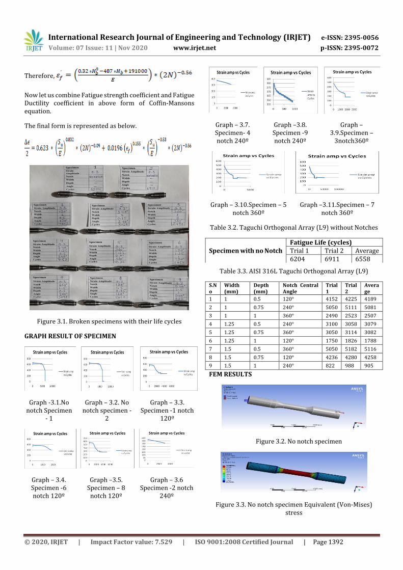
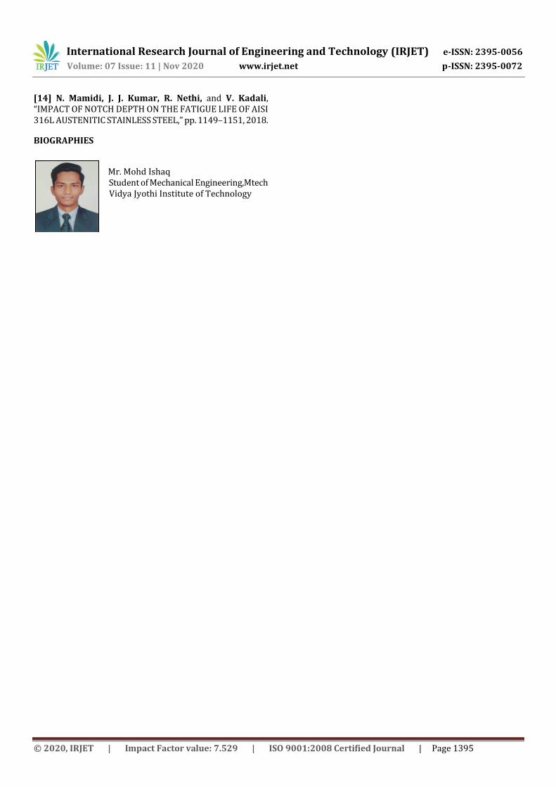
FEM RESULTS
Figure 3.2. No notch specimen
Figure 3.3. No notch specimen Equivalent (Von-Mises) stress

International Research Journal of Engineering and Technology (IRJET) e-ISSN: 2395-0056
Volume: 07 Issue: 11 | Nov 2020 www.irjet.net p-ISSN: 2395-0072
© 2020, IRJET | Impact Factor value: 7.529 | ISO 9001:2008 Certified Journal | Page 1393
Figure. 3.4. Specimen-1 with 1200 notch Equivalent (Von- Mises) stress
Figure. 3.5. Specimen-2 with 2400 notch Equivalent (Von-Mises) stress
Figure 3.6. Specimen – 3 with 3600 notch Equivalent (Von-Mises) Stress
Figure 3.7. Specimen-4 with 2400 notch Equivalent (Von-Mises)stress
Figure 3.8. Specimen – 5 with 3600 notch Equivalent (Von-Mises) Stress
Figure 3.9. Specimen – 6 with 1200 notch Equivalent (Von-Mises) Stress
Figure 3.10. Specimen – 7 with 3600 notch Equivalent (Von-Mises)Stress
Figure 3.11. Specimen – 8 with 1200 notch Equivalent (Von-Mises) Stress
Figure 3.12. Specimen – 9 with 2400 notch Equivalent (Von- Mises)Stress
3.2. Taguchi Design.
To Create Taguchi Design and to create a robust parameter design to identify controllable factors in this research process that can minimize variation and make the product insensitive to alter in the factors. Taguchi design includes control factors, which are factors in the process that can control the data, which are factors that one cannot control when the product or process is in use. Minitab provides two types of Taguchi designs. When you create a design, Minitab stores the design information in the worksheet and they are Static and Dynamic design data. The Taguchi results of the runs mentioned in below are as follows;
Taguchi analysis: f versus w, d, a
Response Table for Signal to Noise Ratios
Nominal is best (10×Log10(Ybar2/s2))
Level w d a
1 * * *

International Research Journal of Engineering and Technology (IRJET) e-ISSN: 2395-0056
Volume: 07 Issue: 11 | Nov 2020 www.irjet.net p-ISSN: 2395-0072
© 2020, IRJET | Impact Factor value: 7.529 | ISO 9001:2008 Certified Journal | Page 1394
2 * * *
3 * * *
Delta * * *
Rank 2 2 2
Response Table for Means
Level w d a
1 3419 4657 3845
2 3412 4140 2725
3 3701 1733 3960
Delta 289 2924 1235 Rank 3 1 2
Figure3.13. Fatigue life vs Notch Parameters
4. CONCLUSIONS
CONCLUSION AND SCOPE FOR FURTHER WORK
From the experimental work undertaken and subsequent Taguchi analysis, it can be concluded that;
1. Fatigue life drastically reduces with the introduction of notch on the specimen. The maximum fall was in the tune of around 84%.
2. The Fatigue life is found to have optimal parameter condition at the width being at highest level, depth at lowest level and notch central angle at the highest level.
3. Width and notch central angle have marginal impact on the fatigue life reduction. However, when the angle was 360˚ irrespective of the depth and width of the notch, there was considerable reduction in the fatigue life.
4. Muralidharan-Manson Method gave rough idea on the magnitude of strain amplitude to be maintained and this reduced the n trail-and-number of error, approach experiments to fix upon the magnitude of strain amplitude
ACKNOWLEDGEMENT
The authors express their deep sense of gratitude to Dr. Sreeram Reddy, HOD, Department of Mechanical Engineering, Vidya Jyothi Institute of Technology, Hyderabad for the support extended during the execution of the
research. The authors also thank Dr J.Jagadesh Kumar, Professor (Dept. of Mech. Engg.), VJIT, for the help and guidance provided during this work.
REFERENCES
[1]B. Boardman, “Fatigue Resistance of Steels,” ASM Met. Handbook-Properties Sel. irons, steels, high-performance Alloy. (10th edition), vol. 1, pp. 673–688, 1990.
[2]F. C. Campbell, “© 2008 ASM International. All Rights Reserved. Elements of Metallurgy and Engineering Alloys (#05224G) www.asminternational.org,” ASM Int., vol. 83, no. 1, p. 317, 2008.
[3]S. Upadhyay, “Low Cycle Fatigue and Post Fatigue Tensile Behaviour of a Non-Conventional Austenitic Stainless Steel, M.Tech Thesis, National Institute of Technology Rourkela, May 2014.
[4] Ralph I. Stephens, Ali Fatemi, Robert R. Stephens, Henry O. Fuchs, Metal Fatigue in Engineering, 2nd Edition,ISBN: 978-0-471-51059-8, 2000.
[5] H. E. Williams, H. Ottsen, F. V. Lawrence, W. H. Munse, “the Effects of Weld Geometry on the Fatigue Behavior of Welded Connections,” Illinois Coop. Highw. Res. Progr., no. 366, 1970.
[6] B. Pollard and R. J. Cover, “Fatigue of Steel Weldments,” Weld. Res. Suppl., vol. 83, no. c, pp. 544–554, 1972.
[7] C. Huettig, “WELD - STATIC AND FATIGUE STRENGTH -III,” Adapt. Phys. Act. Q., vol. 17, no. 4, pp. 468–469, 2000.
[8] W. Fricke, “Fatigue analysis of welded joints: State of development,” Mar. Struct., vol. 16, no. 3, pp. 185–200, 2003.
[9] P. Bernasovský, “Failure Analysis of Welded Components – Importance for Technical Practice,” IIW Int. Congr. Cent. East Eur. Reg. Slovakia, High Tatras, StaráLesn. 14 – 16 Oct. 2009, no. October, pp. 14–16, 2009.
[10] M. T. Yu, D. L. DuQuesnay, and T. H. Topper, “Notch fatigue behaviour of SAE1045 steel,” Int. J. Fatigue, vol. 10, no. 2, pp. 109–116, 1988.
[11] M. Makkonen, “Notch size effects in the fatigue limit of steel,” Int. J. Fatigue, vol. 25, no. 1, pp. 17–26, 2002.
[12] Y. T. Li, B. Chen, and C. F. Yan, “Effect of Parameters of Notch on Fatigue Life of Shaft Based on Product Lifecycle Management,” Mater. Sci. Forum, vol. 638–642, pp. 3864–3869, 2010.
[13] Y. T. Li, B. Chen, and C. F. Yan, “Effect of Parameters of Notch on Fatigue Life of Shaft Based on Product Lifecycle Management,” Mater. Sci. Forum, vol. 638–642, pp. 3864–3869, 2010.
International Research Journal of Engineering and Technology (IRJET) e-ISSN: 2395-0056
Volume: 07 Issue: 11 | Nov 2020 www.irjet.net p-ISSN: 2395-0072
© 2020, IRJET | Impact Factor value: 7.529 | ISO 9001:2008 Certified Journal | Page 1395
[14] N. Mamidi, J. J. Kumar, R. Nethi, and V. Kadali, “IMPACT OF NOTCH DEPTH ON THE FATIGUE LIFE OF AISI 316L AUSTENITIC STAINLESS STEEL,” pp. 1149–1151, 2018.
BIOGRAPHIES
Mr. Mohd Ishaq
Student of Mechanical Engineering,Mtech Vidya Jyothi Institute of Technology