
Edition Installing and Splicing Textile Conveyor Belts · 2017-05-10 · Conveyor Belts -...
34
Edition Installing and Splicing Textile Conveyor Belts Conveyor Belt Group
Transcript of Edition Installing and Splicing Textile Conveyor Belts · 2017-05-10 · Conveyor Belts -...

Edition
Installing and Splicing Textile Conveyor Belts
Conveyor Belt Group


ContiTech
Transportbandsysteme
GmbH
We are a company of the ContiTech Group. 120 years of
experience in rubber processing and a comprehensive
range of products and services have made us the leading
manufacturer of conveyor belts and service materials that
meet various requirements in every industry. The product
range extends from textile and steel conveyor belts to
special conveyor belts with a wide variety of accessories.
Our products and services remain state-of-the-art thanks
to continuous research and development based on careful
basic research. We evaluate our ongoing material investi-
gations and practical testing in collaboration with our raw
materials suppliers. This gives rise to products that com-
bine reliability and long life for every materials-handling
task at an optimum cost/benefit ratio. We provide our
customers with all-round service. It extends to consulta-
tion in planning conveyors and in-service product support.
Conti Edition
This is the title of ContiTech's literature on conveying
technology. Previously printed brochures provide
information on product lines, accessories and mainte-
nance instructions. Other subjects will be dealt with in
the future.
Conveyor Belts -
Installation and Splicing
The operational reliability of conveyor belts is deter-
mined to a large extent by the strength of their splices.
This brochure gives information on splicing. It also
contains instructions on the proper method of installing
conveyor belts and identifies the materials and tools
needed for this. The summary of individual operations
(listed in the appendix) will help belt installation and
vulcanisation experts to plan and carry out their work.
The ContiTech Group is a
development partner and an
original equipment supplier to
many industries, and it provides
high-grade functional parts,
components and systems. It is a
part of the Continental Corporation
with over 30 companies specializing
in rubber and plastics technologies
in Europe and sharing their
common know-how.
This is what the ContiTech brand is
all about.


ContiTech Conveyor Belt Systems
ContiTech Textile Conveyor Belts -
Ensuring Safe and Problem-Free Conveying
ContiTech Group of Continental AG

4
CONTENTS
Transporting, Pulling-ln and Splicing
Conveyor Belts with Textile Plies
Page 1 Preparing for Installation _______________________________________ 5
1.1 Packaging for transportation __________________________________ 5
1.1.1 Dimensions _______________________________________________ 5
1.1.1.1 Round coils _______________________________________________ 5
1.1.1.2 Spiral and long coils _________________________________________ 8
1.1.2 Loading and unloading _______________________________________ 8
1.1.3 Storage ___________________________________________________ 8
1.2 Preparation for pulling in the belt ______________________________ 8
1.2.1 Jacking up and pulling in the belt _______________________________ 8
1.2.2 Pulling in the belt ___________________________________________ 9
1.2.3 Selecting the vulcanisation site ________________________________ 9
1.2.4 Looping up the spliced belt before pulling it in ____________________ 10
1.3 Preparing the work site _____________________________________ 11
1.3.1 Preparing the work place ____________________________________ 11
1.3.2 Tightening and clamping the belt ______________________________ 11
1.4 Vulcanisation equipment ____________________________________ 12
1.4.1 Heating plates ____________________________________________ 12
1.4.2 Pressure device ___________________________________________ 12
1.4.3 Accessories ______________________________________________ 12
1.5 Tools ___________________________________________________ 13
2. Splicing the fabric belt ______________________________________ 14
2.1 Non-detachable joins _______________________________________ 14
2.1.1 How the splice works and demands made on it ___________________ 14
2.1.2 Types of splices ___________________________________________ 15
2.1.2.1 Splicing conveyor belts with more than two plies __________________ 16
2.1.2.2 Splicing conveyor belts with two plies __________________________ 16
2.1.2.3 Splicing conveyor belts with a single ply ________________________ 17
2.1.3 Aligning the belt ends _______________________________________ 17
2.1.4 Preparing the belt ends _____________________________________ 18
2.1.4.1 Normal stepped splices _____________________________________ 18
2.1.4.2 Splicing 2-ply belts with intermediate ties _______________________ 21
2.1.4.3 Finger splices _____________________________________________ 22
2.1.5 Completing the splice _______________________________________ 23
2.1.5.1 Setting up the vulcanisation equipment ________________________ 23
2.1.5.2 Vulcanisation _____________________________________________ 24
2.1.6 Splices with special requirements _____________________________ 25
2.1.6.1 Splices for short conveyor belts _______________________________ 25
2.1.6.2 Splicing conveyer belts with patterned covers ___________________ 25
2.1.7 Splicing materials __________________________________________ 26
2.2 Detachable splices _________________________________________ 27
2.2.1 Hook fasteners ____________________________________________ 27
2.2.2 Articulated or hinge fasteners ________________________________ 27
Glossary _________________________________________________ 28
5
Transporting, Pulling-In and Splicing
Conveyor Belts with Textile Plies
The tension members in this type of belt are generally two or more textile plies (1)
that are joined by layers of a special rubber compound (2). The textile plies are
nearly always fabric with different designs. Single, tightly woven fabric plies are
also used for special requirements such as underground mining. The core of
the belt is generally protected above and below by rubber covers (3) and, if
necessary, on the sides by rubber edges (4).
Textile conveyor belts are described in a short form. For example, EP 500/3
identifies a belt with 3 plies of a fabric with polyester threads (E) in the warp
direction and polyamide threads (P) in the weft direction with an overall break-
ing strength of at least 500 N/mm belt width (see DIN 22102, part 1).
Conveyor belts with textile plies generally must be spliced on site, and they are
frequently made up of several lengths of belting. The procedures to be used
during transportation, pulling into the conveyor (i.e. installation) and splicing
are described below.
1. Preparing for Installation
1.1 Packaging for Transportation
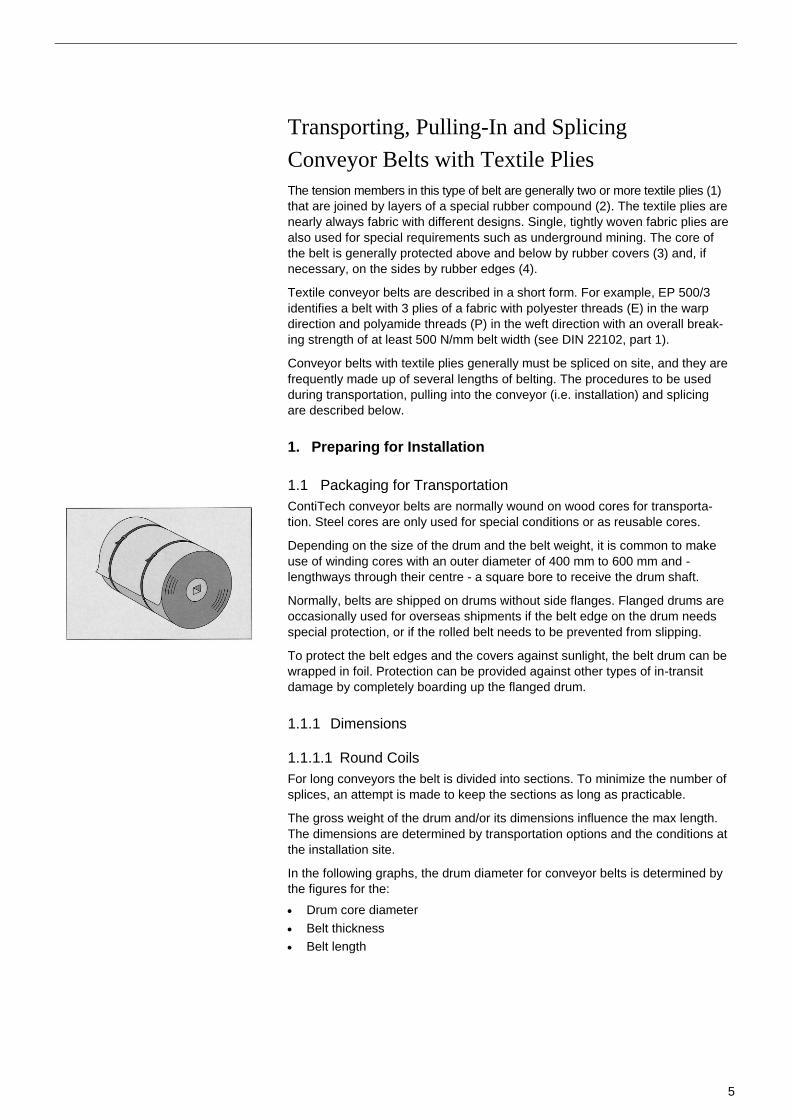
ContiTech conveyor belts are normally wound on wood cores for transporta-
tion. Steel cores are only used for special conditions or as reusable cores.
Depending on the size of the drum and the belt weight, it is common to make
use of winding cores with an outer diameter of 400 mm to 600 mm and -
lengthways through their centre - a square bore to receive the drum shaft.
Normally, belts are shipped on drums without side flanges. Flanged drums are
occasionally used for overseas shipments if the belt edge on the drum needs
special protection, or if the rolled belt needs to be prevented from slipping.
To protect the belt edges and the covers against sunlight, the belt drum can be
wrapped in foil. Protection can be provided against other types of in-transit
damage by completely boarding up the flanged drum.
1.1.1 Dimensions
1.1.1.1 Round Coils
For long conveyors the belt is divided into sections. To minimize the number of
splices, an attempt is made to keep the sections as long as practicable.
The gross weight of the drum and/or its dimensions influence the max length.
The dimensions are determined by transportation options and the conditions at
the installation site.
In the following graphs, the drum diameter for conveyor belts is determined by
the figures for the:
Drum core diameter
Belt thickness
Belt length

6

7
8
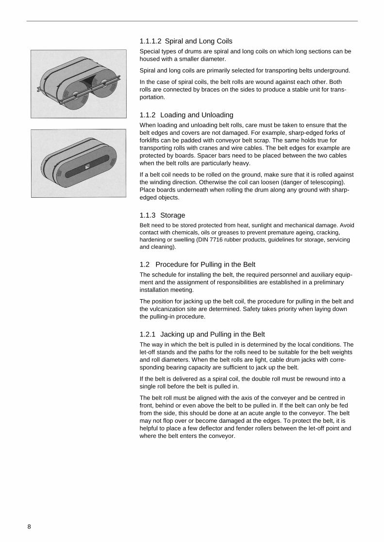
1.1.1.2 Spiral and Long Coils
Special types of drums are spiral and long coils on which long sections can be
housed with a smaller diameter.
Spiral and long coils are primarily selected for transporting belts underground.
In the case of spiral coils, the belt rolls are wound against each other. Both
rolls are connected by braces on the sides to produce a stable unit for trans-
portation.
1.1.2 Loading and Unloading
When loading and unloading belt rolls, care must be taken to ensure that the
belt edges and covers are not damaged. For example, sharp-edged forks of
forklifts can be padded with conveyor belt scrap. The same holds true for
transporting rolls with cranes and wire cables. The belt edges for example are
protected by boards. Spacer bars need to be placed between the two cables
when the belt rolls are particularly heavy.
If a belt coil needs to be rolled on the ground, make sure that it is rolled against
the winding direction. Otherwise the coil can loosen (danger of telescoping).
Place boards underneath when rolling the drum along any ground with sharp-
edged objects.
1.1.3 Storage
Belt need to be stored protected from heat, sunlight and mechanical damage. Avoid
contact with chemicals, oils or greases to prevent premature ageing, cracking,
hardening or swelling (DIN 7716 rubber products, guidelines for storage, servicing
and cleaning).
1.2 Procedure for Pulling in the Belt
The schedule for installing the belt, the required personnel and auxiliary equip-
ment and the assignment of responsibilities are established in a preliminary
installation meeting.
The position for jacking up the belt coil, the procedure for pulling in the belt and
the vulcanization site are determined. Safety takes priority when laying down
the pulling-in procedure.
1.2.1 Jacking up and Pulling in the Belt
The way in which the belt is pulled in is determined by the local conditions. The
let-off stands and the paths for the rolls need to be suitable for the belt weights
and roll diameters. When the belt rolls are light, cable drum jacks with corre-
sponding bearing capacity are sufficient to jack up the belt.
If the belt is delivered as a spiral coil, the double roll must be rewound into a
single roll before the belt is pulled in.
The belt roll must be aligned with the axis of the conveyer and be centred in
front, behind or even above the belt to be pulled in. If the belt can only be fed
from the side, this should be done at an acute angle to the conveyor. The belt
may not flop over or become damaged at the edges. To protect the belt, it is
helpful to place a few deflector and fender rollers between the let-off point and
where the belt enters the conveyor.

9
1.2.2 Pulling in the Belt
Whereas narrow and short belt sections can be pulled in with a cable tension-
er, longer, heavier belts require motor-operated cable winches, or the cables
are attached to appropriate towing machines such as a truck or caterpillar.
Before pulling in the belt, make sure that the bottom of the belt is facing the
support idlers of the carrying run.
The beginning of the belt needs to be prepared in the following way before
being drawn in.
If the belts are heavy, a drawbar is attached to the beginning of the belt to
allow it to be joined to the traction cable. This drawbar consists of two metal
plates or flat iron bars with a number of holes. The belt end is provided with
matching holes, and it is clamped between the two parts of the drawbar with
sufficiently large machine bolts.
The two belt corners of the front belt end are cut back at an angle or elevat-
ed so that they do not hit the trough idlers when pulled in.
If the cable cannot be pulled in the direction of the conveyor run, the cable can
be pulled from the side via hinged idlers or deflection idlers. These idlers are
attached so that the conveyor frame cannot get twisted or otherwise damaged.
Special safety precautions must be taken when drawing in or unrolling a belt in
a conveyor that slopes up or down. If the cable should break or the brake
should fail, it would be impossible to stop the falling belt and it could cause
substantial damage to its surroundings and be damaged itself. This risk can be
reduced by installing a capture device (such as an eccentric trap). We recom-
mend consultation with our installer.
1.2.3 Selecting the Vulcanization Site
For long belt conveyors with a number of belt sections, there are various op-
tions for selecting the vulcanization site. If the local conditions allow you to set
up a good work area near the supporting frame, this option is preferable. In this
case, it is convenient to set up the vulcanization site approximately one section
length away from the end drum. After one length has been pulled in, the let-off
stand is empty, and a new roll can be mounted while splicing the belt. All splic-
es can be made at one site.
The process is as follows:
Section 1 is pulled in, and the end of this section is temporarily connected to
the beginning of section 2 with a flat bar clip. After section 1 has been fed to
the working site, the beginning of section 3 can also be joined with a clip to belt
end 2 and pulled in. If two vulcanizers are available, you can select the first
vulcanization site and then set up a second vulcanization site between the let-
off stand and conveyor head so that two splices can be made simultaneously.
If the conditions near the supporting frame are so poor that the quality of the
splices might suffer at this location, it is preferable for the vulcanization site to
be set up between the drum and the let-off stand.
10
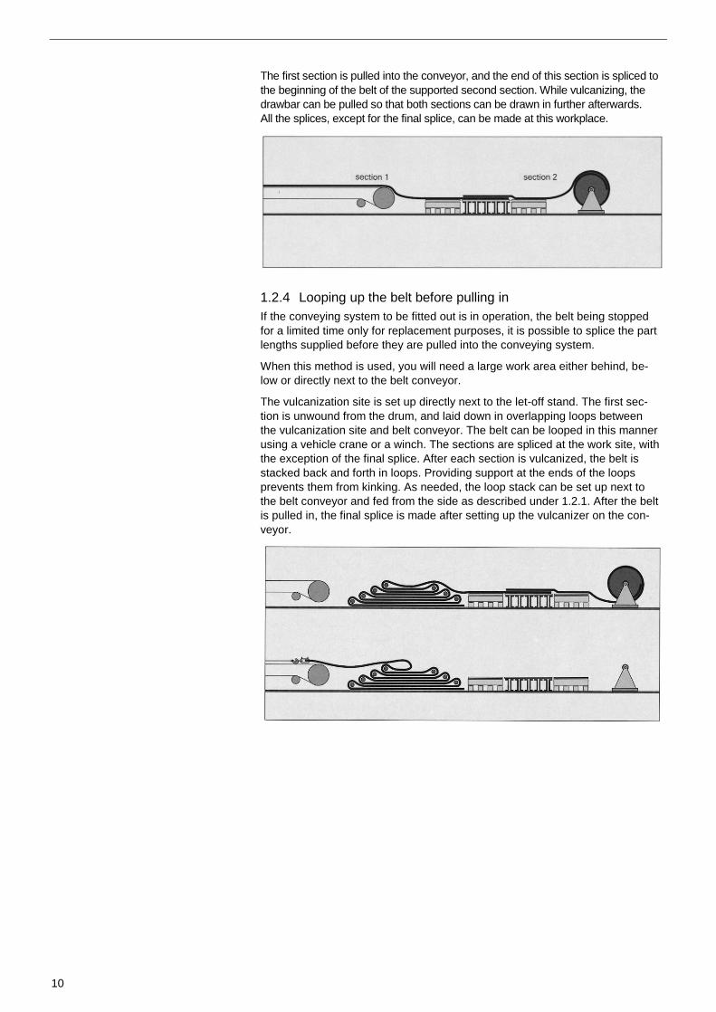
The first section is pulled into the conveyor, and the end of this section is spliced to
the beginning of the belt of the supported second section. While vulcanizing, the
drawbar can be pulled so that both sections can be drawn in further afterwards.
All the splices, except for the final splice, can be made at this workplace.
1.2.4 Looping up the belt before pulling in
If the conveying system to be fitted out is in operation, the belt being stopped
for a limited time only for replacement purposes, it is possible to splice the part
lengths supplied before they are pulled into the conveying system.
When this method is used, you will need a large work area either behind, be-
low or directly next to the belt conveyor.
The vulcanization site is set up directly next to the let-off stand. The first sec-
tion is unwound from the drum, and laid down in overlapping loops between
the vulcanization site and belt conveyor. The belt can be looped in this manner
using a vehicle crane or a winch. The sections are spliced at the work site, with
the exception of the final splice. After each section is vulcanized, the belt is
stacked back and forth in loops. Providing support at the ends of the loops
prevents them from kinking. As needed, the loop stack can be set up next to
the belt conveyor and fed from the side as described under 1.2.1. After the belt
is pulled in, the final splice is made after setting up the vulcanizer on the con-
veyor.

11
1.3 Preparing the Work Site
To make proper splices, the work site must be set up properly, the vulcaniza-
tion equipment must be operating correctly, and the right tools must be used.
1.3.1 Preparing the Workplace
To splice the sections of conveyor belts, the workplace must be at least three
times as long as the splice length. In front of and following the bottom part of
the vulcanization press, worktables of a suitable length are to be set up for
precisely aligning and working on the belt ends.
If splice working area is within the conveyor system, either the appropriate
length of the belt frames are disassembled and the working surface for splicing
the sections is set up on the ground, or the idler assemblies in the carrying run
are removed, and the working surface is erected on side structures. A vulcani-
zation press is not used for cold splicing.
1.3.2 Tightening and Clamping the Belt
The take-up pulley is generally set to the smallest inner circumference since
slack is available after removing the vulcanization equipment and opening the
belt tensioner.
If the tightening path is long enough and there is enough belt length, the take-
up pulley does not have to be set at its end position. This allows sufficient
length for at least one additional splice in the take-up. This means faulty splic-
es can be repaired without having to insert a replacement section. It also has
the advantage that an idler can be removed without having to cut the belt.
To prepare for the final splice, both belt ends are drawn together, i.e. the belt is
tightened to reduce the sag between the idlers to a minimum. The tightening
and clamping method - depending on the length of the conveyor and the force
required to hold the belt - are very different. The clamps that can be used
range from simple wood planks to hydraulic crossbars. Two pairs of crossbars
are required.
When a replacement section is inserted, make sure that the two splices contain-
ing it are at least 5 m apart.

12
1.4 Vulcanization Equipment
Splices and repairs are made at the installation site with portable vulcanization
equipment. The required temperatures and pressure must be maintained over
the entire vulcanization area for the belt to be properly vulcanized.
1.4.1 Heating Plates
The vulcanization temperature is attained by electrically heated plates that are
made of aluminum to save weight. The temperature can be controlled with a
thermostat or PTC thermistor. The heating plates must be designed so that the
temperature is evenly distributed over the entire surface that is to be vulcanized.
The surface area can be heated by placing together several heating plates in a
lengthwise and crosswise direction. The heating plates should extend over the
splice area in the lengthwise direction of the belt by approximately 100 mm.
To ensure sufficient vulcanization of the edges and hold the side shims in
place, the plates should extend at least 50 mm over the side, that is:
Width of the heating surface = belt width + 100 mm
The angle of the heating plates is normally 16° 40'.
(i.e. equivalent to 0.3 x belt width).
When belts are installed for underground coal mines, make sure that only per-
missible firedamp-proof heating plates are used.
1.4.2 Pressure Devise
The pressure required to vulcanize the belt splices can be applied with cross-
bars with tightening bolts mechanically, hydraulically or hydro mechanically.
The pressure must be evenly distributed over the entire surface to be spliced.
Aluminum crossbar pairs are preferable because they are easier to handle.
The specific surface pressure for light conveyor belts should be at least 6
daN/cm2 and 10 daN/cm
2 for heavy belts.
1.4.3 Accessoires
Side shims (side irons) are used with vulcanization equipment to hold the side
of the splice. These shims consist of approx. 60 mm-wide flat metal bars. The
shims must be approximately 0.5 mm thinner than the belt so that the full
amount of pressure can be applied to the splice area.
Another important accessory are panels used for heating. When the heating
surface consists of several pairs of heating plates, the panels are placed be-
tween the heating plates and belt. Steel panels approximately 1.5 mm thick or
aluminum panels approximately 3 mm thick are used.
The dimensions of the panels should be selected so that the sides correspond
with the edges of the heating plates and project approximately 100 mm in the
lengthwise direction of the belt.

13
1.5 Tools
To splice belt ends, the following tools are required.
1. Pressure roller
2. Wire brush (rotating)
3. Right-angle grinder and disk grinder
4. Draw vice or hand vice
5. Rubber mallet
6. Hammer
7. Whisk broom
8. Lift and grip pliers
9. Nippers
10. Chalk
11. Ply separator
12. Ply measuring device
13. Pricker
14. Pricking roller
15. Paint brush
16. Saddler's knife
17. Shoemaker's knife with replacement blades
18. Protractor
19. Saddler's pliers
20. Scissors
21. Snap line
22. Gloves
23. C-clamps
24. Tool bag
25. Whetstone
26. Toothed roller
27. Folding yardstick
28. Measuring tape
29. Protective glasses
30. Circular knife/keyhole saw

14
2. Splicing the Fabric Belt
A distinction is made between detachable and non-detachable joins. The non-
detachable joins (splices) can take more stress than detachable joins. All joins,
however, are weak links in a conveyor belt. Detachable joins are frequently
used in certain industries such as mining, or on machines whenever a non-
detachable splice is not justified due to the large amount of time and expense
involved. This is the case when the belt frequently has to be shortened or
lengthened or when downtime would be costly.
2.1 Non-detachable Joins
A difference is made between vulcanized splices and cold splices. The tech-
niques for manufacturing both types of splices are identical up to a certain
point. In this brochure, the vulcanized splice is described in detail. The features
of the cold splice are found in the ContiTech brochure, “Kaltverbindung von
Gewebegurten mil dem Kontaktklebstoff CONTI SECUR®” (Cold Splice of Fab-
ric Belts with the Contact Adhesive CONTI SECUR®).
2.1.1 How the Splice Works and Demands Made On It
The basis for creating a splice is strong adhesion between the textile layers and
the surrounding rubber. At the connecting interface, the layers of the two belt
ends are overlapped as prescribed. For a vulcanized splice, the ends are embed-
ded in vulcanizing solution and vulcanized. For cold splices, the function of the
rubber cement is assumed by the ContiTech contact adhesive CONTI SECUR®.
The tension is transferred via the surrounding rubber from the plies of one belt
section to the plies of the other belt section. The length of the step is important.
The length is adapted to the type of fabric and belt.
In general, the splices have the same thickness and flexural strength as the
conveyor belt. If a thick spot cannot be avoided, it may not exceed 3 mm. If
scrapers are used to clean the belt, the splice can be damaged if it is more
than 3 mm thicker than the rest.
15
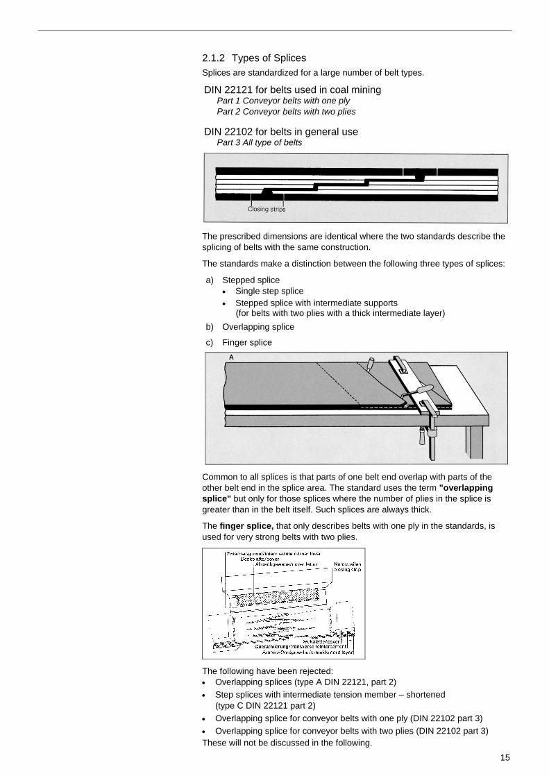
2.1.2 Types of Splices
Splices are standardized for a large number of belt types.
DIN 22121 for belts used in coal mining
Part 1 Conveyor belts with one ply
Part 2 Conveyor belts with two plies
DIN 22102 for belts in general use
Part 3 All type of belts
The prescribed dimensions are identical where the two standards describe the
splicing of belts with the same construction.
The standards make a distinction between the following three types of splices:
a) Stepped splice
Single step splice
Stepped splice with intermediate supports (for belts with two plies with a thick intermediate layer)
b) Overlapping splice
c) Finger splice
Common to all splices is that parts of one belt end overlap with parts of the
other belt end in the splice area. The standard uses the term "overlapping
splice" but only for those splices where the number of plies in the splice is
greater than in the belt itself. Such splices are always thick.
The finger splice, that only describes belts with one ply in the standards, is
used for very strong belts with two plies.
The following have been rejected:
Overlapping splices (type A DIN 22121, part 2)
Step splices with intermediate tension member – shortened
(type C DIN 22121 part 2)
Overlapping splice for conveyor belts with one ply (DIN 22102 part 3)
Overlapping splice for conveyor belts with two plies (DIN 22102 part 3)
These will not be discussed in the following.
16
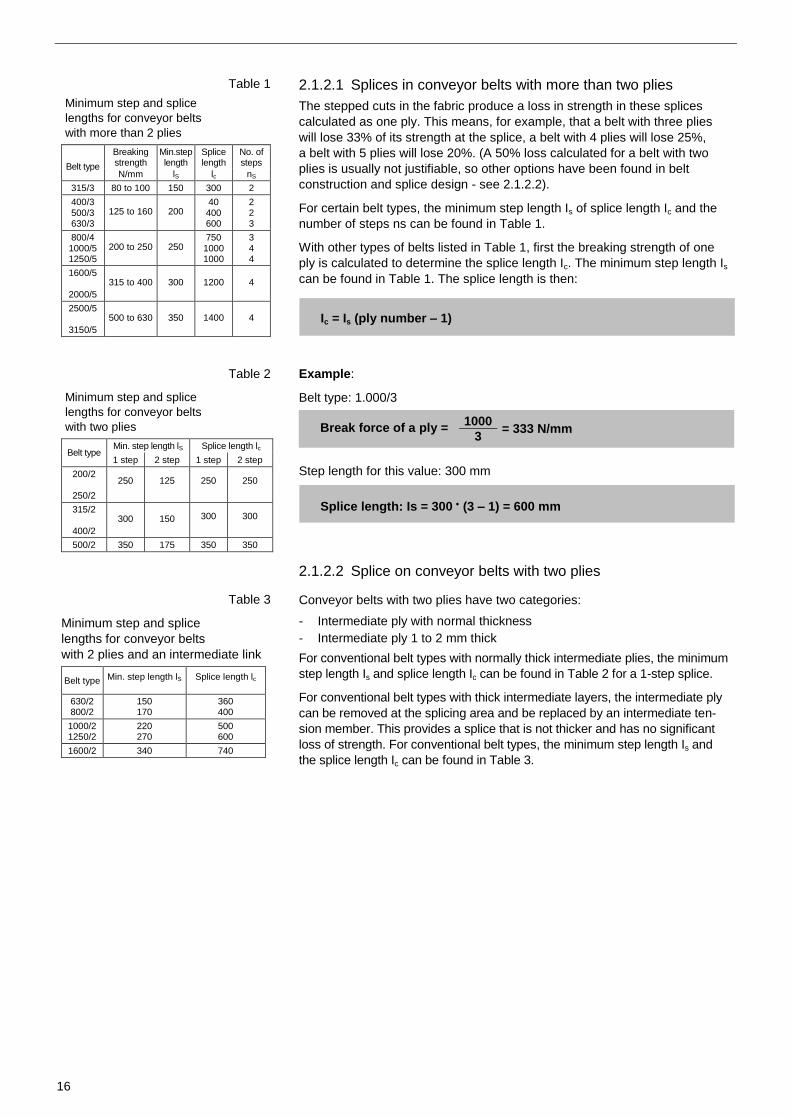
Table 1
Minimum step and splice
lengths for conveyor belts
with more than 2 plies
Belt type
Breaking strength
Min.step length
Splice length
No. of steps
N/mm lS lc nS
315/3 80 to 100 150 300 2
400/3 500/3 630/3
125 to 160 200 40 400 600
2 2 3
800/4 1000/5 1250/5
200 to 250 250 750 1000 1000
3 4 4
1600/5
2000/5
315 to 400 300 1200 4
2500/5
3150/5
500 to 630 350 1400 4
Table 2
Minimum step and splice
lengths for conveyor belts
with two plies
Belt type Min. step length lS Splice length lc
1 step 2 step 1 step 2 step
200/2
250/2
250 125 250 250
315/2
400/2
300 150 300 300
500/2 350 175 350 350
Table 3
Minimum step and splice
lengths for conveyor belts
with 2 plies and an intermediate link
Belt type Min. step length lS Splice length lc
630/2 800/2
150 170
360 400
1000/2 1250/2
220 270
500 600
1600/2 340 740
2.1.2.1 Splices in conveyor belts with more than two plies
The stepped cuts in the fabric produce a loss in strength in these splices
calculated as one ply. This means, for example, that a belt with three plies
will lose 33% of its strength at the splice, a belt with 4 plies will lose 25%,
a belt with 5 plies will lose 20%. (A 50% loss calculated for a belt with two
plies is usually not justifiable, so other options have been found in belt
construction and splice design - see 2.1.2.2).
For certain belt types, the minimum step length Is of splice length Ic and the
number of steps ns can be found in Table 1.
With other types of belts listed in Table 1, first the breaking strength of one
ply is calculated to determine the splice length Ic. The minimum step length Is
can be found in Table 1. The splice length is then:
Ic = Is (ply number – 1)
Example:
Belt type: 1.000/3
Break force of a ply = 1000
= 333 N/mm 3
Step length for this value: 300 mm
Splice length: Is = 300 (3 – 1) = 600 mm
2.1.2.2 Splice on conveyor belts with two plies
Conveyor belts with two plies have two categories:
- Intermediate ply with normal thickness
- Intermediate ply 1 to 2 mm thick
For conventional belt types with normally thick intermediate plies, the minimum
step length Is and splice length Ic can be found in Table 2 for a 1-step splice.
For conventional belt types with thick intermediate layers, the intermediate ply
can be removed at the splicing area and be replaced by an intermediate ten-
sion member. This provides a splice that is not thicker and has no significant
loss of strength. For conventional belt types, the minimum step length Is and
the splice length Ic can be found in Table 3.
17
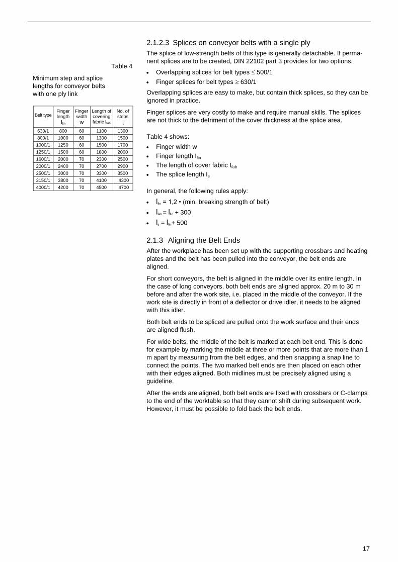
Table 4
Minimum step and splice
lengths for conveyor belts
with one ply link
Belt type Finger length
lfin
Finger width
w
Length of covering fabric lfab
No. of steps
ls
630/1 800 60 1100 1300
800/1 1000 60 1300 1500
1000/1 1250 60 1500 1700
1250/1 1500 60 1800 2000
1600/1 2000 70 2300 2500
2000/1 2400 70 2700 2900
2500/1 3000 70 3300 3500
3150/1 3800 70 4100 4300
4000/1 4200 70 4500 4700
2.1.2.3 Splices on conveyor belts with a single ply
The splice of low-strength belts of this type is generally detachable. If perma-
nent splices are to be created, DIN 22102 part 3 provides for two options.
Overlapping splices for belt types 500/1
Finger splices for belt types 630/1
Overlapping splices are easy to make, but contain thick splices, so they can be
ignored in practice.
Finger splices are very costly to make and require manual skills. The splices
are not thick to the detriment of the cover thickness at the splice area.
Table 4 shows:
Finger width w
Finger length Ifin
The length of cover fabric Ifab
The splice length Is
In general, the following rules apply:
lfin = 1,2 • (min. breaking strength of belt)
lfab = lfin + 300
ls = lfin+ 500
2.1.3 Aligning the Belt Ends
After the workplace has been set up with the supporting crossbars and heating
plates and the belt has been pulled into the conveyor, the belt ends are
aligned.
For short conveyors, the belt is aligned in the middle over its entire length. In
the case of long conveyors, both belt ends are aligned approx. 20 m to 30 m
before and after the work site, i.e. placed in the middle of the conveyor. If the
work site is directly in front of a deflector or drive idler, it needs to be aligned
with this idler.
Both belt ends to be spliced are pulled onto the work surface and their ends
are aligned flush.
For wide belts, the middle of the belt is marked at each belt end. This is done
for example by marking the middle at three or more points that are more than 1
m apart by measuring from the belt edges, and then snapping a snap line to
connect the points. The two marked belt ends are then placed on each other
with their edges aligned. Both midlines must be precisely aligned using a
guideline.
After the ends are aligned, both belt ends are fixed with crossbars or C-clamps
to the end of the worktable so that they cannot shift during subsequent work.
However, it must be possible to fold back the belt ends.

18
2.1.4 Preparing the Belt Ends
When splicing the ends, follow these basic rules:
When removing residual rubber on the surface of the fabric, do not damage
the fabric.
Cut butt ends at approx. 30° to provide more adhesive surfaces.
Roughen interfaces between the covers and rubber edges.
Spread rubber cement solutions sparingly. They only serve to improve the
adhesiveness while assembling and actually can harm the bond after vul-
canization.
2.1.4.1 Normal Stepped Splices
Cutting the Belt Ends
Before beginning work, the type of fabric joins must be chosen.
Join Angles
Fabric joins are always cut at an angle. The angled join prevents the join from
being stressed over the entire width of the belt when it bends around pulleys
and idlers. The greater the angle, the less the stress on the join, and the
longer the splice. An angle of 16° 40' has proven to be a satisfactory standard.
It is easy to construct with simple tools (0.3 x belt width). The angle is
identified as la. For a splice length Is, the required length of belt for the splice
is calculated as follows:
lr = ls + la
For particularly small pulley diameters, V-cut splices can be used.
These splices require a more skilled technique, however.
Step Direction
If the belt is scraped hard when being cleaned, the splice should be made so
that the scraper does not scrape "against" the stepped design. It is better when
the direction of belt travel goes "with" the stepped design.
The covers are left on the outer fabric and are only removed from the outer
fabric joins to later receive the closing strip.
The steps are created in the fabric plies, starting with one belt end while the
other end is folded back. A try square is used to draw a 45° angle from both
edges. The midline is used as a reference line for wide belts, and the right
angle is drawn from there. On the marked belt end, the angle la is drawn from a
belt edge and marked for example with a snap line.
19
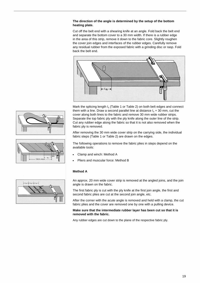
The direction of the angle is determined by the setup of the bottom
heating plate.
Cut off the belt end with a shearing knife at an angle. Fold back the belt end
and separate the bottom cover to a 30 mm width. If there is a rubber edge
in the area of this strip, remove it down to the fabric core. Slightly roughen
the cover join edges and interfaces of the rubber edges. Carefully remove
any residual rubber from the exposed fabric with a grinding disc or rasp. Fold
back the belt end.
Mark the splicing length Is (Table 1 or Table 2) on both belt edges and connect
them with a line. Draw a second parallel line at distance Is + 30 mm, cut the
cover along both lines to the fabric and remove 30 mm wide rubber strips.
Separate the top fabric ply with the ply knife along the outer line of the strip.
Cut any rubber edge along the fabric so that it is not also removed when the
fabric ply is removed.
After removing the 30 mm wide cover strip on the carrying side, the individual
fabric steps (Table 1 or Table 2) are drawn on the edges.
The following operations to remove the fabric plies in steps depend on the
available tools:
Clamp and winch: Method A
Pliers and muscular force: Method B
Method A
An approx. 20 mm wide cover strip is removed at the angled joins, and the join
angle is drawn on the fabric.
The first fabric ply is cut with the ply knife at the first join angle, the first and
second fabric plies are cut at the second join angle, etc.
After the corner with the acute angle is removed and held with a clamp, the cut
fabric plies and the cover are removed one by one with a pulling device.
Make sure that the intermediate rubber layer has been cut so that it is
removed with the fabric.
Any rubber edges are cut down to the plane of the respective fabric ply.
20
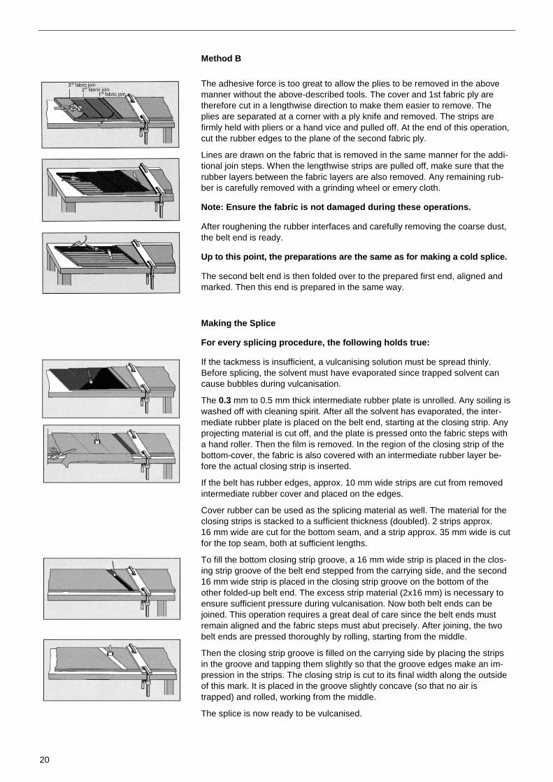
Method B
The adhesive force is too great to allow the plies to be removed in the above
manner without the above-described tools. The cover and 1st fabric ply are
therefore cut in a lengthwise direction to make them easier to remove. The
plies are separated at a corner with a ply knife and removed. The strips are
firmly held with pliers or a hand vice and pulled off. At the end of this operation,
cut the rubber edges to the plane of the second fabric ply.
Lines are drawn on the fabric that is removed in the same manner for the addi-
tional join steps. When the lengthwise strips are pulled off, make sure that the
rubber layers between the fabric layers are also removed. Any remaining rub-
ber is carefully removed with a grinding wheel or emery cloth.
Note: Ensure the fabric is not damaged during these operations.
After roughening the rubber interfaces and carefully removing the coarse dust,
the belt end is ready.
Up to this point, the preparations are the same as for making a cold splice.
The second belt end is then folded over to the prepared first end, aligned and
marked. Then this end is prepared in the same way.
Making the Splice
For every splicing procedure, the following holds true:
If the tackmess is insufficient, a vulcanising solution must be spread thinly.
Before splicing, the solvent must have evaporated since trapped solvent can
cause bubbles during vulcanisation.
The 0.3 mm to 0.5 mm thick intermediate rubber plate is unrolled. Any soiling is
washed off with cleaning spirit. After all the solvent has evaporated, the inter-
mediate rubber plate is placed on the belt end, starting at the closing strip. Any
projecting material is cut off, and the plate is pressed onto the fabric steps with
a hand roller. Then the film is removed. In the region of the closing strip of the
bottom-cover, the fabric is also covered with an intermediate rubber layer be-
fore the actual closing strip is inserted.
If the belt has rubber edges, approx. 10 mm wide strips are cut from removed
intermediate rubber cover and placed on the edges.
Cover rubber can be used as the splicing material as well. The material for the
closing strips is stacked to a sufficient thickness (doubled). 2 strips approx.
16 mm wide are cut for the bottom seam, and a strip approx. 35 mm wide is cut
for the top seam, both at sufficient lengths.
To fill the bottom closing strip groove, a 16 mm wide strip is placed in the clos-
ing strip groove of the belt end stepped from the carrying side, and the second
16 mm wide strip is placed in the closing strip groove on the bottom of the
other folded-up belt end. The excess strip material (2x16 mm) is necessary to
ensure sufficient pressure during vulcanisation. Now both belt ends can be
joined. This operation requires a great deal of care since the belt ends must
remain aligned and the fabric steps must abut precisely. After joining, the two
belt ends are pressed thoroughly by rolling, starting from the middle.
Then the closing strip groove is filled on the carrying side by placing the strips
in the groove and tapping them slightly so that the groove edges make an im-
pression in the strips. The closing strip is cut to its final width along the outside
of this mark. It is placed in the groove slightly concave (so that no air is
trapped) and rolled, working from the middle.
The splice is now ready to be vulcanised.

21
2.1.4.2 Splicing 2-Ply Belts with Intermediate Fabric
This splice is a special type of step splice. The general rules need to be ob-
served. In the following, the special technique to make this splice will be de-
scribed.
At the belt end, the angle of bevelling and belt steps are marked (Table 3). Any
rubber edges are cut off with a rasp in the middle between the fabric layers.
First, the step furthest away from the belt end is created. A shearing knife cuts
through the cover, and the first fabric ply is cut off at a distance la from the belt
end. A fabric corner is released from the intermediate rubber layer. A clamp is
attached to the corner, and the fabric and cover are pulled off with a hoist
winch to second line Is. The intermediate rubber layer should remain on the
bottom fabric layer.
The lifted ply is folded back to the splice and clamped with C-clamps. Proceeding from the cut edge, a 30 mm wide cover strip is marked, cut to the fabric and pulled off.
The belt end is cut off at the marked angle line.
After folding back the belt, a 30 mm wide cover strip is marked, cut and pulled
off on the backing side.
The belt end is rolled back, and the cover and fabric are pulled off the front
step. Then the intermediate rubber layer is removed from the entire splicing
surface.
The other belt end is now rolled to the prepared first end and marked. The
second belt end is then prepared in the same way.
Both belt ends are now pulled together until the bottom fabric plies precisely
face each other. The belt ends are realigned and clamped with C-clamps.
After the top plies of both belt ends are drawn back, the rubberised intermedi-
ate ties are inserted. A piece is cut to the width of the fabric core and length Is
and rolled up with the film onto the splice. In the gap between the folded-back
fabric steps and the inserted intermediate tie, a narrow strip of rubber approx.
0.5 mm thick is inserted and pressed. The film is removed, and the two top
plies of both belt ends are placed on the join and thoroughly rolled.

22
2.1.4.3 Finger Splices
A finger splice is used for very strong conveyor belts with one or two plies. It
only performs well if it is completed very carefully. It is very important to have a
uniformly thick intermediate rubber layer between the fingers of both belt ends.
Unlike other types of splices on fabric belts, the covers are completely removed
in the splice area and are rebuilt.
After the belt parts to be spliced are aligned, they are clamped to the worktable
so that the ends can be folded back. On the top belt, the final belt end is
marked with a transverse line at a right angle to the belt axis.
When finger splices are used, it is not necessary for the fingertips to run at an
angle. They generally do run at an angle, however, to correspond to rhombus-
shaped heating plates. The transverse line or a line drawn at an angle to the
transverse line becomes a reference line for the following operation. This ref-
erence line is marked.
Starting from the reference line, splice length Is (Table 4) is marked, and any
rubber edges are cut off this area with a shearing knife. On the cover of the top
belt piece, the zone of the finger with length If (Table 4) is marked by two lines
parallel to the reference line. Between these lines, the individual fingers are
drawn with finger width wf (Table 4). Make sure that the finger width at the
edges is at least wf/2. The width of the fingers between them approximates the
desired width wf. If many splices of this kind are to be made, it is recom-
mendable to prepare a template to draw the finger pattern.
The two belt ends are realigned and prevented from moving by being held in
C-clamps. Holes 8 mm in diameter are drilled at the base corners of the fingers
through both belt ends. They serve as target points for the cut lines. This helps
the matching of the finger patterns of the two belt ends.
The fingers are marked and cut out. This requires a great amount of precision
and is best done with a rotating, motor-driven circular knife. A keyhole saw may
also be used.
Starting from the reference line, the cut lines are drawn for the cover joins. The
cover is cut at a 30° angle to the belt plane to prepare for removing the cover.
Starting at the cover joins, the covers are removed on the top and bottom sides.
Both belt ends are then folded back. The heating panels and padding cloth are
placed on the heating plates. The bottom cover - whose thickness has been
reduced by the thickness of the cover fabric - is cut at a 30° angle on one side,
placed at the cover join of the first belt section, marked at the join of the se-
cond belt section and then cut. The rubberised bottom cover fabric is placed on
top, and any fabric extending over the side is cut off. The provided compensat-
ing rubber plates are placed on both ends of the cover fabric. The plates are
adapted on one side to the ends of the jaggedly-cut cover fabric. On the other
side, they are cut-to-size as needed.
The fingers of one side are rolled onto the bottom plate prepared in this man-
ner. The join rubber strip approx. 2 mm thick (thickness of the belt core) is
placed on the face of the fingers and pressed down firmly. The fingers of the
other belt side are pushed against the join strip. Both fabric ends are carefully
rolled on, starting from the middle.
The cover fabric with compensating rubber plates and a top cover is construct-
ed in the same way. If the belt has rubber edges, they are made from cover
material at the end.
23
2.1.5 Completing the Splice
2.1.5.1 Setting up the Vulcanisation Equipment
The entire join area is covered with a padding cloth, as is the bottom side of
the splice.
Thin fabric or shirting strips approx. 100 mm wide are placed in steps at the
cover splices to increase vulcanisation pressure and reduce the thickness in
this transition area.
Shims or edge bars, that are approx. 0.5 mm thinner than the belt thickness,
are placed along both ends of the belt.
As described under 1.4 in reference to the bottom side, heating panels are
placed over the entire splice surface. Then the top heating plates are laid on
flush with the edges of the bottom plates. When several plate pairs are used,
the plate joins should be offset.
The top crossbars are mounted precisely aligned with the bottom cross bars.
Make sure that a plate pair is centred over the cover joins and over plate
aggregates.
Tie bolts are inserted in the ends of the press bars and slightly tightened so
that the edge bars can be wedged by the hydraulic pressure bars.
The prescribed pressure is applied evenly. The join is now ready to be
vulcanised.
If other vulcanisation devices are used, such as ones with hydro mechanical
pressure systems, follow the instructions of their manufacturer.
24
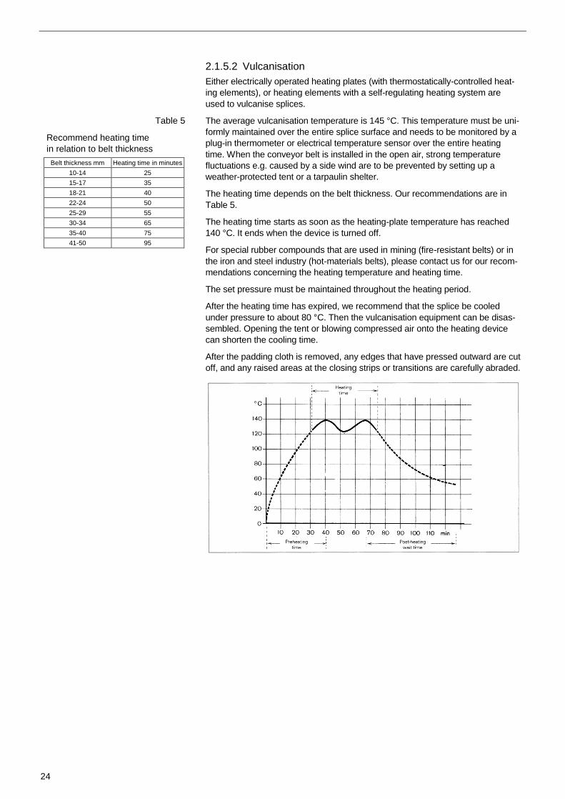
Table 5
Recommend heating time
in relation to belt thickness
Belt thickness mm Heating time in minutes
10-14 25
15-17 35
18-21 40
22-24 50
25-29 55
30-34 65
35-40 75
41-50 95
2.1.5.2 Vulcanisation
Either electrically operated heating plates (with thermostatically-controlled heat-
ing elements), or heating elements with a self-regulating heating system are
used to vulcanise splices.
The average vulcanisation temperature is 145 °C. This temperature must be uni-
formly maintained over the entire splice surface and needs to be monitored by a
plug-in thermometer or electrical temperature sensor over the entire heating
time. When the conveyor belt is installed in the open air, strong temperature
fluctuations e.g. caused by a side wind are to be prevented by setting up a
weather-protected tent or a tarpaulin shelter.
The heating time depends on the belt thickness. Our recommendations are in
Table 5.
The heating time starts as soon as the heating-plate temperature has reached
140 °C. It ends when the device is turned off.
For special rubber compounds that are used in mining (fire-resistant belts) or in
the iron and steel industry (hot-materials belts), please contact us for our recom-
mendations concerning the heating temperature and heating time.
The set pressure must be maintained throughout the heating period.
After the heating time has expired, we recommend that the splice be cooled
under pressure to about 80 °C. Then the vulcanisation equipment can be disas-
sembled. Opening the tent or blowing compressed air onto the heating device
can shorten the cooling time.
After the padding cloth is removed, any edges that have pressed outward are cut
off, and any raised areas at the closing strips or transitions are carefully abraded.
25
2.1.6 Splices with Special Requirements
2.1.6.1 Splices for Short Conveyor Belts
The precise length does not have to be determined for long conveyor belts
that are spliced to form an endless loop on the conveyor system. This is not
the case for short conveyor belts that are spliced to form an endless belt
separate from the conveyor system and then placed on the system. They
must be spliced to a specified inner length, usually in a workshop.
The required length is usually the inner perimeter such as the length meas-
ured by running a measuring tape around the pulleys. The stretched length
is greater by approx. 3x the belt thickness. The cut belt length is determined
as follows:
Endless inner length + overlap lo + 3x belt thickness.
2.1.6.2 Joining Conveyer Belts with Patterned Covers
For inclined conveying, every belt has a threshold angle at which the conveyed
material starts to slide down the belt. By making a patterned cover, this threshold
angle can be increased. However, such cover designs are particularly proble-
matic when vulcanising splices. Two types of splices are relevant in this regard:
Belts with fine cover patterns
Belts with chevron cleats
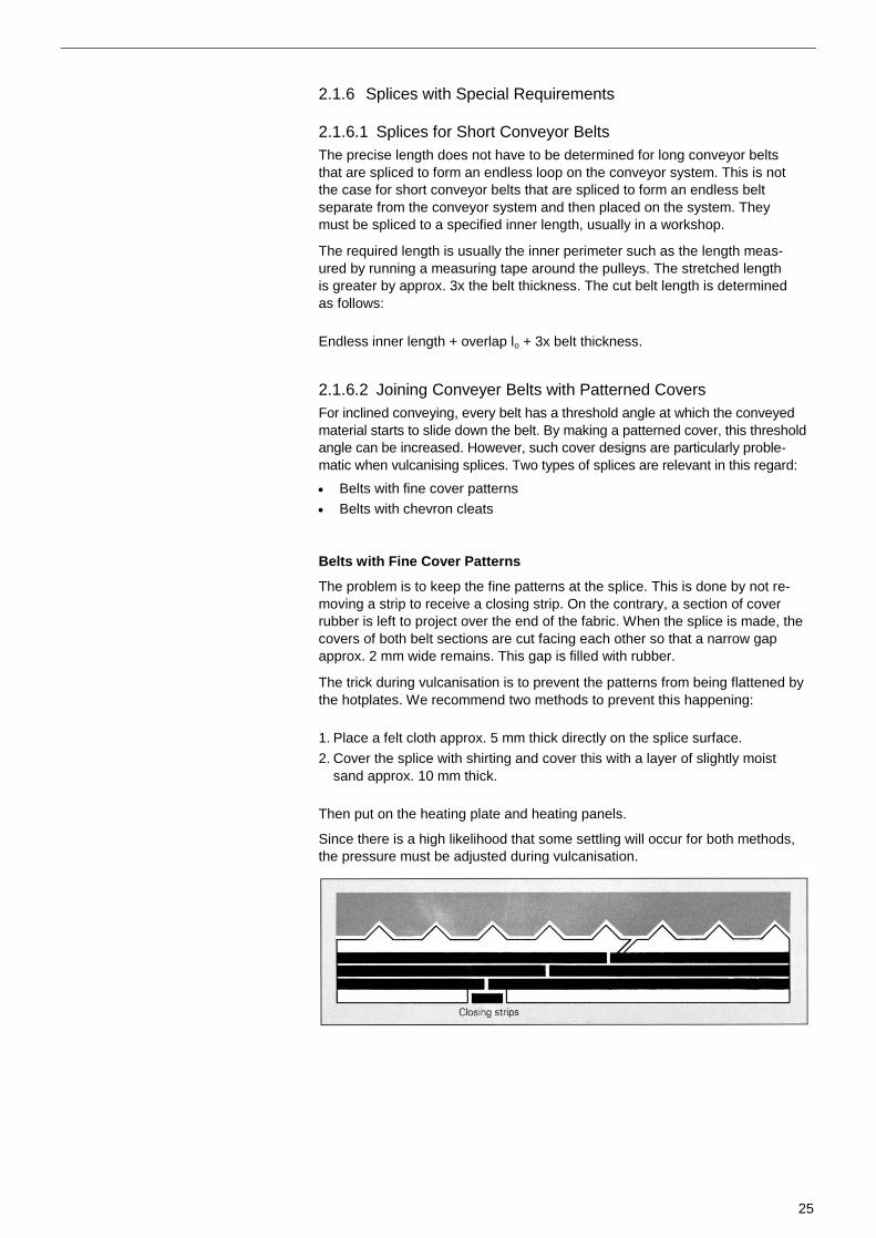
Belts with Fine Cover Patterns
The problem is to keep the fine patterns at the splice. This is done by not re-
moving a strip to receive a closing strip. On the contrary, a section of cover
rubber is left to project over the end of the fabric. When the splice is made, the
covers of both belt sections are cut facing each other so that a narrow gap
approx. 2 mm wide remains. This gap is filled with rubber.
The trick during vulcanisation is to prevent the patterns from being flattened by
the hotplates. We recommend two methods to prevent this happening:
1. Place a felt cloth approx. 5 mm thick directly on the splice surface.
2. Cover the splice with shirting and cover this with a layer of slightly moist
sand approx. 10 mm thick.
Then put on the heating plate and heating panels.
Since there is a high likelihood that some settling will occur for both methods,
the pressure must be adjusted during vulcanisation.
26
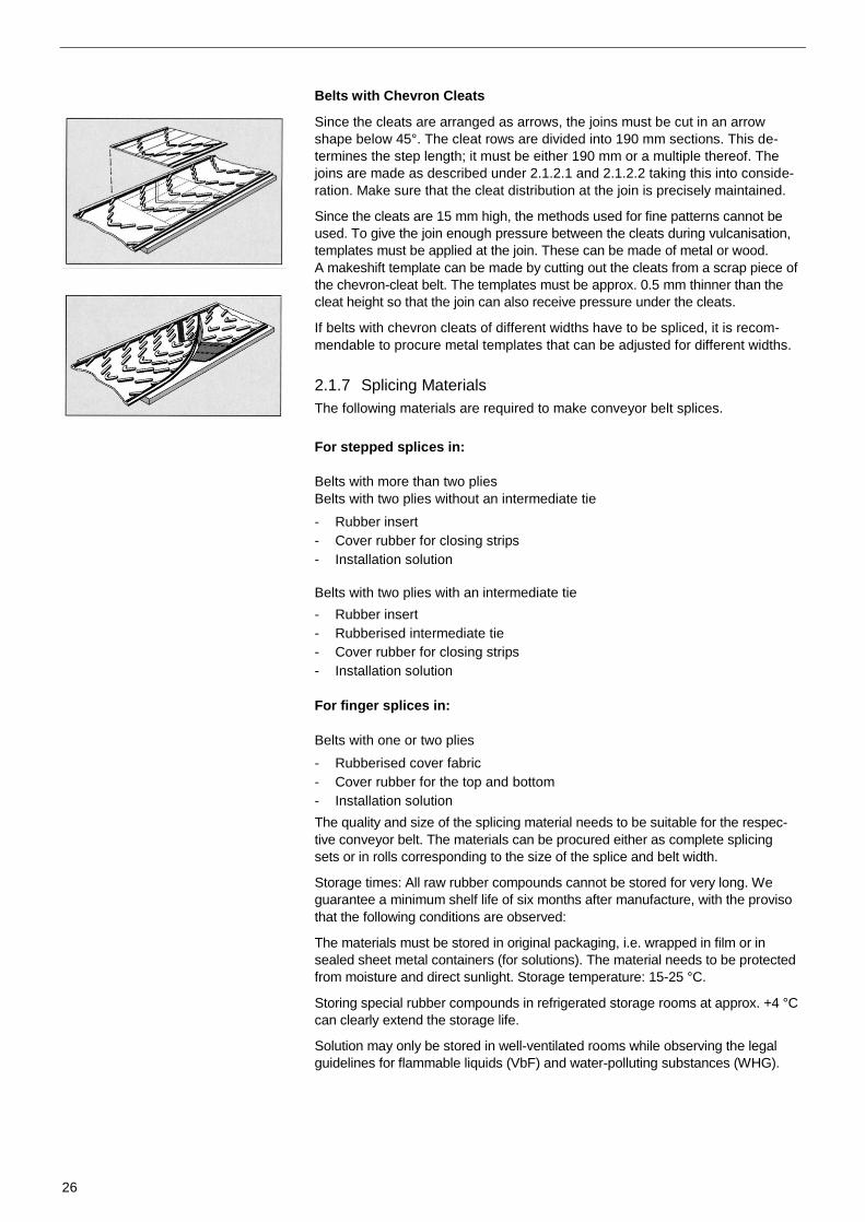
Belts with Chevron Cleats
Since the cleats are arranged as arrows, the joins must be cut in an arrow
shape below 45°. The cleat rows are divided into 190 mm sections. This de-
termines the step length; it must be either 190 mm or a multiple thereof. The
joins are made as described under 2.1.2.1 and 2.1.2.2 taking this into conside-
ration. Make sure that the cleat distribution at the join is precisely maintained.
Since the cleats are 15 mm high, the methods used for fine patterns cannot be
used. To give the join enough pressure between the cleats during vulcanisation,
templates must be applied at the join. These can be made of metal or wood.
A makeshift template can be made by cutting out the cleats from a scrap piece of
the chevron-cleat belt. The templates must be approx. 0.5 mm thinner than the
cleat height so that the join can also receive pressure under the cleats.
If belts with chevron cleats of different widths have to be spliced, it is recom-
mendable to procure metal templates that can be adjusted for different widths.
2.1.7 Splicing Materials
The following materials are required to make conveyor belt splices.
For stepped splices in:
Belts with more than two plies
Belts with two plies without an intermediate tie
- Rubber insert
- Cover rubber for closing strips
- Installation solution
Belts with two plies with an intermediate tie
- Rubber insert
- Rubberised intermediate tie
- Cover rubber for closing strips
- Installation solution
For finger splices in:
Belts with one or two plies
- Rubberised cover fabric
- Cover rubber for the top and bottom
- Installation solution
The quality and size of the splicing material needs to be suitable for the respec-
tive conveyor belt. The materials can be procured either as complete splicing
sets or in rolls corresponding to the size of the splice and belt width.
Storage times: All raw rubber compounds cannot be stored for very long. We
guarantee a minimum shelf life of six months after manufacture, with the proviso
that the following conditions are observed:
The materials must be stored in original packaging, i.e. wrapped in film or in
sealed sheet metal containers (for solutions). The material needs to be protected
from moisture and direct sunlight. Storage temperature: 15-25 °C.
Storing special rubber compounds in refrigerated storage rooms at approx. +4 °C
can clearly extend the storage life.
Solution may only be stored in well-ventilated rooms while observing the legal
guidelines for flammable liquids (VbF) and water-polluting substances (WHG).

27
2.2 Detachable Splices
Detachable belt connections can be made easily and quickly. However, their
dynamic strength is less than for non-detachable splices. Nevertheless, the
results are always satisfactory when the elements of detachable joins are used
for belts whose fabric has been specially developed for this kind of connection.
There are different types of connectors on the market:
Hook fasteners
Articulated or hinge fasteners
2.2.1 Hook Fasteners
Hook fasteners are made of round wire with polished tips. The belt ends are
cut at a right angle. The belt width narrows toward the cut edge by approx. 20
mm so that the connection is not damaged if the belt runs to the side.
The hooks consist of several rows of adjacent hooks. The tips of the hooks are
open. To press the hooks into the belt end, a special pair of pressing pliers is
used. The belt end is clamped tight. The hooks are held straight in a comb and
pressed with the two levers of the pressing pliers into the end of the belt, and
bent around the base of the hooks after passing through the other side of the
belt.
Hooks of a simpler design merely penetrate the fabric and are bent on the
other side.
The hooks form a series of eyelets in front of the cut edge of the belt. The se-
ries of eyelets of two belt sections can be pushed into each other. If a coupling
rod is forced through them, they form a hinge.
There are specific hooks for specific belt thicknesses.
2.2.2 Articulated or Hinge Fasteners
Articulated or hinge fasteners are hinge-like connecting elements stamped out
of sheet steel. The belt ends are cut at a right angle. The belt width narrows by
approx. 20 mm so that the connection is not damaged when the belt runs to
the side. The individual hinge elements are pushed toward the cut edge. De-
pending on the design, the elements are fixed to the belt end by driving in U-
shaped cramps or pointed rivets. The elements of two belt ends mesh like a
comb. Both belt sections are connected with a coupling rod.

28
Glossary Page
Accessories____________________________________________________ 12
Aligning _________________________________________ 5,14,15,17,18,19,20
Angled cut _____________________________________________ 5,15,16,19
Belt tensioner ___________________________________________________ 8
Cold splice ________________________________________________ 5,11,17
Detachable connection _____________________________________ 11,14,24
Drawing in ___________________________________________________ 8,9
Grasping _____________________________________________________ 11
Heating panel ___________________________________________ 9,20,21,22
Heating plates _________________________________ 8,9,12,14,16,19,20,22
Heating time ___________________________________________________ 12
Installation solution _________________________________________ 18,20,25
Join lengths ___________________________________________ 8,12,14,15,20
Long rolls ______________________________________________________ 8
Looping Up ____________________________________________________ 10
Non-detachable join __________________________________________ 11,14
Padding cloth ________________________________________________ 5,14
Pressure (vulcanisation) __________________________________ 5,9,21,22,23
Pressure crossbars _________________________________________ 20,21,22
Shims _____________________________________________________ 8,9,21
Spiral rolls ______________________________________________________ 8
Splicing materials _______________________________________________ 24
Storage
- Belt roll _______________________________________________________ 5
- Splicing materials ______________________________________________ 26
Temperature (vulc.) ___________________________________________ 8,22
Tightening __________________________________________________ 11,22
Tightening crossbars _____________________________________________ 8
Tools _______________________________________________________ 8,13
Transportation packaging _________________________________________ 5
Vulcanisation____________________________________________ 8,18,21,22
Vulcanisation equipment _______________________________ 8,9,10,12,21,23
Vulcanisation pressure ___________________________________ 8,9,21,22,23
Vulcanisation site ________________________________________________ 5
Worksite ___________________________________________________ 5,7,11

ContiTech. Get more with elastic technology.
The contents of this publication are the result of extensive research and application engineering experience. All information and comments are provided in good faith on
the basis of what is known; they do not vouch for warranted qualities and do not exempt the user from own verification, also with respect to third-party property rights.
No liability on whatever legal grounds is assumed for the advice given herein. This does not apply in the event that we or our legal representatives or senior executives
can be shown to have acted with wrongful intent or gross negligence. Any liability is excluded for damage due to minor negligence. This disclaimer also covers the
personal liability of our legal representatives and employees or other official agents. © 2010 by ContiTech AG, Hannover. All rights reserved.
The ContiTech division
of the Continental Corporation
is a development partner and
original equipment supplier
to numerous industries for
high-quality functional parts,
components and systems.
With its know-how in rubber
and plastics technology,
ContiTech contributes signifi-
cantly to industrial progress
and mobility that is safe, com-
fortable and eco-friendly.
www.contitech.de/conveyorbelts
WT
281
4 E
P
rinte
d w
ith C
ont
iTec
h o
ffse
t p
rintin
g b
lank
ets
on
ble
ache
d p
aper
fre
e o
f ch
lorin
e
Conveyor Belt Group
ContactContiTech Transportbandsysteme GmbHD-37154 NortheimPhone: +49 5551 702 - [email protected]
Your local contact:www.contitech.de/contactlocator