Edfa Example
4
Faculty of Electrical Engineering Universiti Teknologi Malaysia VOL. 11, NO. 1, 2009, 34-37 ELEKTRIKA http://fke.utm.my/elektrika 34 EDFA Gain Optimization for WDM System Farah Diana Binti Mahad 1* and Abu Sahmah Bin Mohd Supa’at 2 1 Faculty of Electrical Engineering, Universiti Teknologi Malaysia, 81310 UTM Skudai, Johor, Malaysia. 2 Department of Optic and Telematic Engineering , Faculty of Electrical Engineering, Universiti Teknologi Malaysia, 81310 UTM Skudai, Johor, Malaysia. * Corresponding author: [email protected], Tel: 607-5535205, Fax: 607-556 6272 Abstract : The gain flatness of erbium-doped fiber amplifier (EDFA) is a key device for wavelength division multiplexing (WDM) application in modern optical network systems. The purpose of this paper is to correct the gain non-uniformity for each channel in order to equalize the amplitude gain in a wavelength division multiplexing (WDM) system. The system is simulated using Optisystem software to achieve gain flatness of EDFA through optimized fiber length and pump power. The gains are flattened within 24±0.299dB from 1546nm to 1558nm band of wavelength with noise figure (NF) <6dB and bit error rate (BER) <10 -9 for 16-channels simultaneous amplification in a single stage EDFA. A WDM system which includes an EDFA is modeled and obtained maximum uniformed gains. Keywords: EDFA, gain flatness, fiber length, pump power, WDM 1. INTRODUCTION EDFA is an optical amplifier that uses a doped optical fiber as a gain medium to amplify an optical signal. The signal which is to be amplified and a pump laser are multiplexed into the doped fiber, and the signal is amplified through interaction with the doping ions. EDFA is the best known and most frequently used optical amplifier suited to low loss optical window of silica based fiber. A particular attraction of EDFAs is their large gain bandwidth, which is typically tens of nanometers and thus actually it is more than enough to amplify data channels with the highest data rates without introducing any effects of gain narrowing. A single EDFA may be used for simultaneously amplifying many data channels at different wavelengths within the gain region. Before such fiber amplifiers were available, there was no practical method for amplifying all channels between long fiber spans of a fiber-optic link. One had to split all data channels, detect and amplify them electronically, optically resubmit and again combine them. The introduction of fiber amplifiers thus brought an enormous reduction in the complexity, along with a corresponding increase in reliability. In WDM systems by multiplexing, a stream of wavelength channels particularly in C and L-band regimes can simultaneously amplify to a desired power level where the amplification of any particular channel is dependent on the signal wavelength, the number of signals present in the system, the input signal powers and its absorption and emission cross-sections [1]. The gain-flattened erbium-doped fiber amplifier (EDFA) is a key component in long haul multichannel lightwave transmission systems such as the Wavelength Division Multiplexing (WDM) [2]. One difficulty in implementing a WDM system including EDFA’s is that the EDFA ga in spectrum is wavelength dependent. In a WDM system, the EDFA does not necessary amplify the wavelength of the channels equally. EDFA in a WDM system are often required to have equalized gain spectra in order to achieve uniform output powers and similar signal-noise ratios (SNR) [3]. There are several methods in designing a flat spectral gain EDFA such as by controlling the doped fiber length and the pump power [2,4], proper choosing of optical notch filter’s characteristic [5], by using an acousto-optic tunable filter [6] and by employing an inhomogeneously broadened gain medium [7]. This paper achieves gain flatness of EDFA by controlling the doped fiber length and the pump power for a given input power of -26dBm and a desired output power of more than 8dBm. 2. METHOD The software Optisystem is used to design the EDFA in the WDM system. The system consists of 16 input signals (channels), an ideal multiplexer, two isolators, a pump laser, erbium doped fiber, demultiplexer, photodetector PIN, low pass Bessel filter and 3R regenerator as shown in Figure 1. The input of the system is 16 equalized wavelength multiplexed signals in the wavelength region of 12nm (1546nm-1558nm) with 0.8nm channels spacing. The power of each channel is -26dBm. The pumping at 980nm is used to excite the doped atoms to a higher energy level. An input optical isolator prevents Amplified Spontaneous Emission (ASE) and signals from propagating in backward direction. Otherwise, reflected ASE would reduce the population inversion, hence reducing the gain and increasing the noise figure. The output isolator prevents light from output reflections re- entering in the EDFA. The desired gain is 23dB and
Transcript of Edfa Example

8/6/2019 Edfa Example
http://slidepdf.com/reader/full/edfa-example 1/4
Faculty of Electrical EngineeringUniversiti Teknologi Malaysia
VOL. 11, NO. 1, 2009, 34-37 ELEKTRIKAhttp://fke.utm.my/elektrika
34
EDFA Gain Optimization for WDM System
Farah Diana Binti Mahad 1* and Abu Sahmah Bin Mohd Supa’at 2
1Faculty of Electrical Engineering, Universiti Teknologi Malaysia, 81310 UTM Skudai, Johor, Malaysia.2Department of Optic and Telematic Engineering , Faculty of Electrical Engineering, Universiti Teknologi Malaysia, 81310
UTM Skudai, Johor, Malaysia.
*Corresponding author: [email protected], Tel: 607-5535205, Fax: 607-5566272
____________________________________________________________________________________________________
Abstract : The gain flatness of erbium-doped fiber amplifier (EDFA) is a key device for wavelength division multiplexing(WDM) application in modern optical network systems. The purpose of this paper is to correct the gain non-uniformity foreach channel in order to equalize the amplitude gain in a wavelength division multiplexing (WDM) system. The system issimulated using Optisystem software to achieve gain flatness of EDFA through optimized fiber length and pump power. The
gains are flattened within 24±0.299dB from 1546nm to 1558nm band of wavelength with noise figure (NF) <6dB and biterror rate (BER) <10 -9 for 16-channels simultaneous amplification in a single stage EDFA. A WDM system which includesan EDFA is modeled and obtained maximum uniformed gains.
Keywords: EDFA, gain flatness, fiber length, pump power, WDM____________________________________________________________________________________________________
1. INTRODUCTION
EDFA is an optical amplifier that uses a doped opticalfiber as a gain medium to amplify an optical signal. Thesignal which is to be amplified and a pump laser aremultiplexed into the doped fiber, and the signal isamplified through interaction with the doping ions. EDFAis the best known and most frequently used opticalamplifier suited to low loss optical window of silicabased fiber.
A particular attraction of EDFAs is their large gainbandwidth, which is typically tens of nanometers and thusactually it is more than enough to amplify data channelswith the highest data rates without introducing any effectsof gain narrowing. A single EDFA may be used forsimultaneously amplifying many data channels atdifferent wavelengths within the gain region. Before suchfiber amplifiers were available, there was no practicalmethod for amplifying all channels between long fiberspans of a fiber-optic link. One had to split all datachannels, detect and amplify them electronically,optically resubmit and again combine them. Theintroduction of fiber amplifiers thus brought an enormousreduction in the complexity, along with a correspondingincrease in reliability.
In WDM systems by multiplexing, a stream of wavelength channels particularly in C and L-bandregimes can simultaneously amplify to a desired powerlevel where the amplification of any particular channel isdependent on the signal wavelength, the number of signals present in the system, the input signal powers andits absorption and emission cross-sections [1].
The gain-flattened erbium-doped fiber amplifier(EDFA) is a key component in long haul multichannellightwave transmission systems such as the WavelengthDivision Multiplexing (WDM) [2]. One difficulty inimplementing a WDM system including EDFA’s is that
the EDFA gain spectrum is wavelength dependent. In aWDM system, the EDFA does not necessary amplify thewavelength of the channels equally. EDFA in a WDMsystem are often required to have equalized gain spectrain order to achieve uniform output powers and similarsignal-noise ratios (SNR) [3]. There are several methods
in designing a flat spectral gain EDFA such as bycontrolling the doped fiber length and the pump power[2,4], proper choosing of optical notch filter’scharacteristic [5], by using an acousto-optic tunable filter[6] and by employing an inhomogeneously broadenedgain medium [7]. This paper achieves gain flatness of EDFA by controlling the doped fiber length and the pumppower for a given input power of -26dBm and a desiredoutput power of more than 8dBm.
2. METHOD
The software Optisystem is used to design the EDFA inthe WDM system. The system consists of 16 input signals(channels), an ideal multiplexer, two isolators, a pumplaser, erbium doped fiber, demultiplexer, photodetectorPIN, low pass Bessel filter and 3R regenerator as shownin Figure 1.
The input of the system is 16 equalized wavelengthmultiplexed signals in the wavelength region of 12nm(1546nm-1558nm) with 0.8nm channels spacing. Thepower of each channel is -26dBm. The pumping at980nm is used to excite the doped atoms to a higherenergy level. An input optical isolator prevents AmplifiedSpontaneous Emission (ASE) and signals frompropagating in backward direction. Otherwise, reflected
ASE would reduce the population inversion, hencereducing the gain and increasing the noise figure. Theoutput isolator prevents light from output reflections re-entering in the EDFA. The desired gain is 23dB and

8/6/2019 Edfa Example
http://slidepdf.com/reader/full/edfa-example 2/4
FARAH DIANA BINTI MAHAD, ABU SAHMAH BIN MOHD SUPA’AT / ELEKTRIKA, 11(1), 2009, 34-37
35
output power of more than 8dBm with a gain flatness of less than 0.5dB. The fiber length and pump power areselected as parameters to be optimized to achieve thedesired gain under output power and gain flatnessconstraints.
Figure 1. Schematic design of EDFA in WDM system
3. RESULTS AND DISCUSSIONThe pump power is bound between 0 and 50mW whilethe fiber length is bound between 1 and 20m. The outputpower is measured by varying pump power for differentfiber length at a constant input power of -26dBm asshown in Figure 2. The output power increases as thepump power increases. For a given pump power, the
output power increases in initial stage and tends todecrease after the fiber length was optimized and remainalmost constant. It is observed that the optimum value of fiber length is between 4m to 6m due to the minimumlosses.
Figure 2. Variation of output power along the fiber lengthfor different pump powers at a constant input power
The optical gain and noise figure (NF) for multi-channels amplification were measured for different pumppowers. The fiber length was set at 4m as the referencesince the optimum fiber length is between 4 to 6m. The
gain flatness is a maximum difference among individualchannels gains when the input power signals are equal.Figure 3 shows the gain and NF variation of -26dBm/champlification for different pump powers. As the pumppower increases, the gain increases while the NFdecreases however, the gain flatness increases along withthe increased of the pump power.
The pump power of 10mW has very low gain andhigh noise figure while the pump power of 40mW hashigh gain and less noise but yield the highest gain flatnessof 1.72dB. This shows that the pump power of 10mW and40mW does not offer good performance for the systemsince the objective of this paper is to achieve the mostequalized gain for every channels. Meanwhile the pumppower of 20mW and 30mW has an acceptable noisefigure of 5dB however the pump power of 30mW yieldhigher gain flatness of 1.41dB as compared to 20mW.Therefore, the best gain and NF was found to be at theoptimum pump power of 20mW with a low gain flatnessof 0.89dB at C-band.
Figure 3. Gain and NF variation of -26dBm/champlification for different pump powers.
Figure 4 shows the results viewed from a visualizerin the OptiSystem software. It displayed a clear view of the gain flatness for different pump powers (10, 20, 30and 40mW) when the power (dBm) versus thewavelength (m). The best case for the maximum gainflatness is at 20mW while the power of 40mW representthe worst case as it yield the most unequalized gain. Thefiber length is varied for different values of pump powersin the range of 20mW to 25mW as shown in Figure 5.
For each pump power, the output power increasesand decreases after reaching a maximum value. As thefiber length increases, Er3+ ions available to exciteincreases and output power increases. After a certainlength, when all pump power is exhausted, the unexcitedEr3+ ions results in the decreased of output power. It isobserved that the optimum fiber length is found to be 5mwith an output power of 8.408dBm. Figure 6 shows the
gain variation of -26dBm/ch amplification for differentpump powers at the optimum fiber length of 5m. As thepump power increases, the gain flatness became worstwhich lead to more noise and bit-error-rate (BER). The

8/6/2019 Edfa Example
http://slidepdf.com/reader/full/edfa-example 3/4
FARAH DIANA BINTI MAHAD, ABU SAHMAH BIN MOHD SUPA’AT / ELEKTRIKA, 11(1), 2009, 34-37
36
maximum gain flatness of 0.299dB was found to be at theoptimum pump power of 23mW with an average gain of 24.27dB.
Figure 4. Output power (red) and noise spectrum (green).
Figure 5. Variation of output power along the fiber lengthfor different pump powers (20-25mW)
The average gain of 24.27dB and NF of 6dB foroptimum pump power (23mW) and fiber length (5m) is
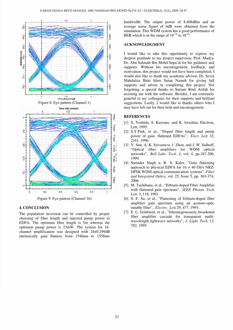
shown in Figure 7. The performance of the system wasanalyzed using BER analyzer as shown in Figure 8. Theeye pattern for Channel 1 gives a big opening whichmeans that the intersymbol interference (ISI) is low. Thewidth of the opening indicates the time over which
sampling for detection is performed. The optimumsampling time corresponding to the maximum eyeopening, yielding the greatest protection against noise.The bit error rate (BER) was measured to be at anaverage of 10 -14 for channel 1. In Figure 9, the bit errorrate (BER) was measured to be at an average of 10 -16 forchannel 16.
Figure 6. Gain variation for different pump power
(20-29mW)
Figure 7. Gain and NF for optimum pump power andfiber length.
8/6/2019 Edfa Example
http://slidepdf.com/reader/full/edfa-example 4/4
FARAH DIANA BINTI MAHAD, ABU SAHMAH BIN MOHD SUPA’AT / ELEKTRIKA, 11(1), 2009, 34-37
37
Figure 8. Eye pattern (Channel 1)
Figure 9. Eye pattern (Channel 16)
4. CONCLUSION
The population inversion can be controlled by properchoosing of fiber length and injected pump power toEDFA. The optimum fiber length is 5m whereas theoptimum pump power is 23mW. The system for 16-channel amplification was designed with 24±0.299dBintrinsically gain flatness from 1546nm to 1558nm
bandwidth. The output power of 8.408dBm and anaverage noise figure of 6dB were obtained from thesimulation. This WDM system has a good performance of BER which is in the range of 10 -14 to 10 -16 .
ACKNOWLEDGMENT
I would like to take this opportunity to express mydeepest gratitude to my project supervisor, Prof. Madya.Dr. Abu Sahmah Bin Mohd Supa’at for his guidance andsupports. Without his encouragement, feedback, andmotivation, this project would not have been completed. Iwould also like to thank my academic advisor, Dr. SeviaMahdaliza Binti Idrus Sutan Nameh for giving fullsupports and advise in completing this project. Notforgetting, a special thanks to Suriani Binti Arifah forassisting me with the software. Besides, I am extremelygrateful to my colleagues for their supports and brilliantsuggestions. Lastly, I would like to thanks others who Imay have left out for their help and encouragement.
REFERENCES[1] S. Yoshida, S. Kuwano, and K. Iwashita, Electron,
Lett, 1995.[2] S.Y.Park, et al., “Doped fiber length and pump
power of gain- flattened EDFAs”, Elect. Lett . 32,2161, 1996.
[3] Y. Sun, A. K. Srivastava, J. Zhou, and J. W. Sulhoff,“Optical fiber amplifiers for WDM opticalnetworks”, Bell Labs. Tech. J ., vol. 4, pp.187-206,1999.
[4] Surinder Singh a, R. S. Kaler, “Gain flatteningapproach to physical EDFA for 16 × 40 Gb/s NRZ-
DPSK WDM optical communication systems”, Fiber and Integrated Optics , vol. 25, Issue 5, pp. 363-374,2006
[5] M. Tachibana, et al., “Erbium-doped Fiber Amplifierwith flattened gain spectrum”, IEEE Photon. Tech.
Lett. 3, 118, 1991.[6] S. F. Su, et al., “Flattening of Erbium-doped fiber
amplifier gain spectrum using an acousto-optictunable filter”, Electro. Lett , 29, 477, 1993.
[7] E. L. Goldstein, et al., “Inhomogeneously broadenedfiber amplifier cascade for transparent multi-wavelength lightwave networks”, J. Light. Tech . 13,782, 1995.