Economy planetary gear unit AG3300- +NPS0xx · Economy planetary gear unit AG3300-+NPS0xx 10...
39
Operation Manual Economy planetary gear unit AG3300- +NPS0xx compatible with highend planetary gear unit AG2300-+SPxxx 1.2 2018-03-28 Version: Date:
Transcript of Economy planetary gear unit AG3300- +NPS0xx · Economy planetary gear unit AG3300-+NPS0xx 10...
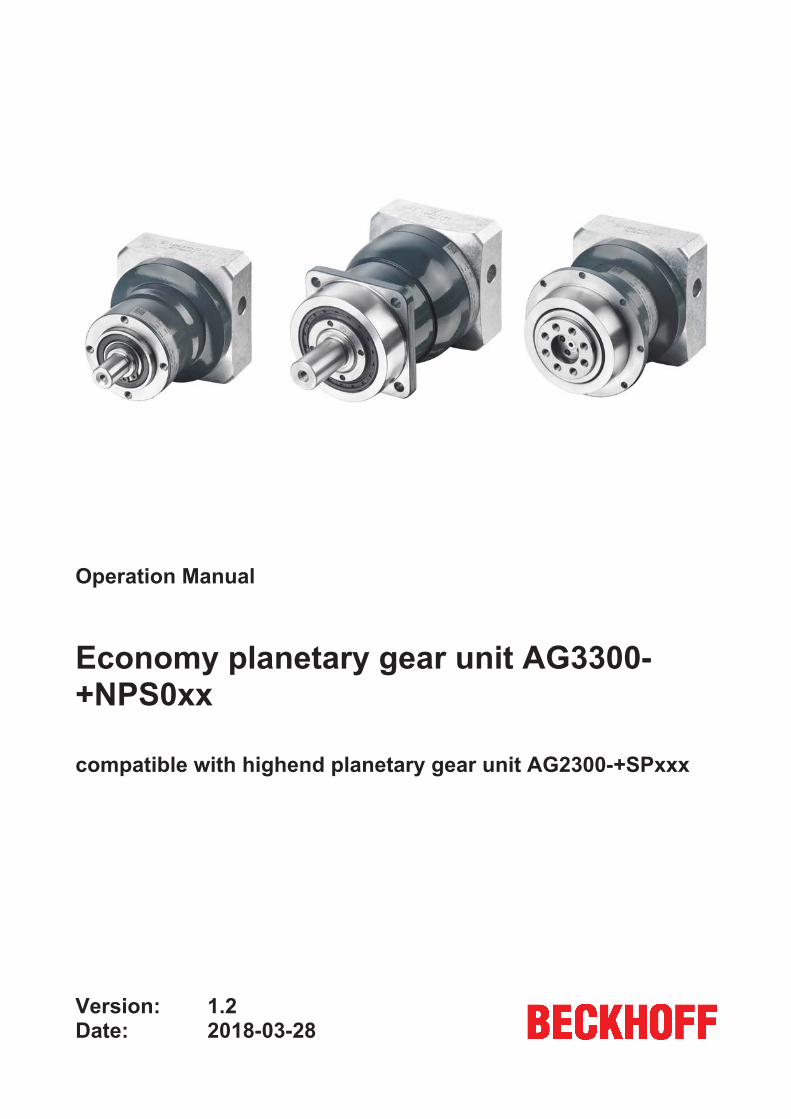
Operation Manual
Economy planetary gear unit AG3300-+NPS0xx
compatible with highend planetary gear unit AG2300-+SPxxx
1.22018-03-28
Version:Date:

Table of content
Economy planetary gear unit AG3300-+NPS0xx
3Version: 1.2
Table of content1 Foreword .................................................................................................................................................... 5
1.1 Notes on the documentation.............................................................................................................. 51.2 Documentation issue status .............................................................................................................. 61.3 Intended use...................................................................................................................................... 6
2 Guidelines and Standards ........................................................................................................................ 72.1 RoHS ................................................................................................................................................. 7
3 For your safety........................................................................................................................................... 83.1 Staff qualification ............................................................................................................................... 83.2 Description of symbols ...................................................................................................................... 93.3 Notes on the AG3300 planetary gear unit ....................................................................................... 10
4 Handling ................................................................................................................................................... 114.1 Transport ......................................................................................................................................... 114.2 Packaging........................................................................................................................................ 114.3 Storage ............................................................................................................................................ 114.4 Maintenance / Cleaning................................................................................................................... 12
4.4.1 Maintenance schedule..................................................................................................... 124.4.2 Maintenance tasks........................................................................................................... 124.4.3 Commissioning after maintenance .................................................................................. 134.4.4 Cleaning agents and cleaning procedures ..................................................................... 14
4.5 Disposal ........................................................................................................................................... 16
5 Product overview..................................................................................................................................... 175.1 Scope of supply AG3300................................................................................................................. 175.2 Name plate AG3300 ........................................................................................................................ 175.3 Type key AG3300............................................................................................................................ 18
6 Technical description.............................................................................................................................. 196.1 Gear unit configuration .................................................................................................................... 196.2 Overview of gear components......................................................................................................... 196.3 General technical data..................................................................................................................... 19
6.3.1 Weight.............................................................................................................................. 19
7 Mechanical installation ........................................................................................................................... 207.1 Important notes................................................................................................................................ 207.2 Mounting the motor on the gear unit................................................................................................ 207.3 Mounting the gear unit at the machine ............................................................................................ 237.4 Tightening torques for common thread sizes .................................................................................. 24
8 Technical data.......................................................................................................................................... 258.1 NPS015 ........................................................................................................................................... 26
8.1.1 Dimension drawing NPS015............................................................................................ 278.2 NPS025 ........................................................................................................................................... 28
8.2.1 Dimension drawing NPS025............................................................................................ 308.3 NPS035 ........................................................................................................................................... 31
8.3.1 Dimension drawing NPS035............................................................................................ 338.4 NPS045 ........................................................................................................................................... 34
Table of content
Economy planetary gear unit AG3300-+NPS0xx
4 Version: 1.2
8.4.1 Dimension drawing NPS045............................................................................................ 35
9 Commissioning........................................................................................................................................ 369.1 Important notes................................................................................................................................ 369.2 Guide for commissioning the gear units .......................................................................................... 379.3 Troubleshooting............................................................................................................................... 38
10 Support and Service................................................................................................................................ 39
Foreword
Economy planetary gear unit AG3300-+NPS0xx
5Version: 1.2
1 Foreword
1.1 Notes on the documentationThis description is only intended for the use of trained specialists in control and automation engineering whoare familiar with the applicable national standards.It is essential that the documentation and the following notes and explanations are followed when installingand commissioning the components. It is the duty of the technical personnel to use the documentation published at the respective time of eachinstallation and commissioning.
The responsible staff must ensure that the application or use of the products described satisfy all therequirements for safety, including all the relevant laws, regulations, guidelines and standards.
Disclaimer
The documentation has been prepared with care. The products described are, however, constantly underdevelopment.We reserve the right to revise and change the documentation at any time and without prior announcement.No claims for the modification of products that have already been supplied may be made on the basis of thedata, diagrams and descriptions in this documentation.
Trademarks
Beckhoff®, TwinCAT®, EtherCAT®, Safety over EtherCAT®, TwinSAFE®, XFC® and XTS® are registeredtrademarks of and licensed by Beckhoff Automation GmbH.Other designations used in this publication may be trademarks whose use by third parties for their ownpurposes could violate the rights of the owners.
Patent Pending
The EtherCAT Technology is covered, including but not limited to the following patent applications andpatents:EP1590927, EP1789857, DE102004044764, DE102007017835with corresponding applications or registrations in various other countries.
The TwinCAT Technology is covered, including but not limited to the following patent applications andpatents:EP0851348, US6167425 with corresponding applications or registrations in various other countries.
EtherCAT® is registered trademark and patented technology, licensed by Beckhoff Automation GmbH,Germany
Copyright
© Beckhoff Automation GmbH & Co. KG, Germany.The reproduction, distribution and utilization of this document as well as the communication of its contents toothers without express authorization are prohibited.Offenders will be held liable for the payment of damages. All rights reserved in the event of the grant of apatent, utility model or design.
Foreword
Economy planetary gear unit AG3300-+NPS0xx
6 Version: 1.2
1.2 Documentation issue status
Origin of the document
This documentation was originally written in German. All other languages are derived from the Germanoriginal.
Product features
Only the product features specified in the current user documentation are valid. Further information given onthe product pages of the Beckhoff homepage, in emails or in other publications is not authoritative.
Version Comment1.2 Chapter update:
Technical data NPS015 – NPS035 8.1 – 8.3(HIGH TORQUE added to technical data)
1.1 Chapter update:Technical data NPS015 – NPS045 8.1 – 8.4(Nominal output torque added to technical data)
1.0 First edition0.0.1 Internal version
1.3 Intended usePlanetary gear units of the AG3xx0 series from Beckhoff are used for the transmission of torques andspeeds. They are suitable for all industrial applications that are not covered by Article II of EC Directive2002/95/EC (restriction of the use of certain hazardous substances in electrical and electronic equipment).
The gear unit is intended for mounting on motors that:• match type B5 (if different, please contact Beckhoff Service);• have a radial or axial runout tolerance compliant with or better than DIN EN 50347;• have a cylindrical shaft end with tolerance class h6 up to k6.
Reasonably foreseeable misuse
Any use that deviates from the approved technical data (e.g. speed, force, temperature) is not use asintended and is therefore not permitted.
Improper use
Planetary gear units of the AG3xx0 series from Beckhoff are not suitable for use in the following areas:
• in ATEX zones without a suitable housing• in areas with aggressive environments (e.g. aggressive gases or chemicals)
In the food industry, the planetary gear unit may only be used beside or below the food area.
CAUTIONDamage from improper use:Any use that goes beyond the intended purpose will result in damage to the planetary gear unit and/or com-ponents of the machine or system. Any improper use is therefore not permitted.
Guidelines and Standards
Economy planetary gear unit AG3300-+NPS0xx
7Version: 1.2
2 Guidelines and Standards CAUTION
Personal injuries!Gear units of the AG3xx0 series from Beckhoff are not products within the meaning of the EC MachineryDirective 2006/42/EC. The intended use of the gear units in machines or systems is prohibited until proof ofthe CE conformity of the entire machine or system has been provided.
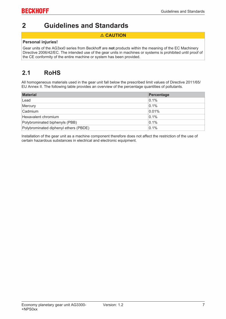
2.1 RoHSAll homogeneous materials used in the gear unit fall below the prescribed limit values of Directive 2011/65/EU Annex II. The following table provides an overview of the percentage quantities of pollutants.
Material PercentageLead 0.1%Mercury 0.1%Cadmium 0.01%Hexavalent chromium 0.1%Polybrominated biphenyls (PBB) 0.1%Polybrominated diphenyl ethers (PBDE) 0.1%
Installation of the gear unit as a machine component therefore does not affect the restriction of the use ofcertain hazardous substances in electrical and electronic equipment.

For your safety
Economy planetary gear unit AG3300-+NPS0xx
8 Version: 1.2
3 For your safetyRead the section on safety and heed the notices to protect yourself against personal injury and materialdamages.
Liability limitations
All components of the AG3xx0 planetary gear unit series are delivered in certain hardware configurations,depending on the application requirements. Unauthorized modifications and changes to the hardwareconfiguration, which go beyond the documented options, are prohibited and nullify the liability of BeckhoffAutomation GmbH & Co. KG.
In addition, the following actions are excluded from the liability of Beckhoff Automation GmbH & Co.KG:
• Failure to comply with this documentation• Improper use• Untrained personnel• Use of unauthorized spare parts
3.1 Staff qualificationAll work steps shown on Beckhoff hardware, in particular on the AG3xx0 planetary gear unit, may only becarried out by specialist personnel with knowledge of control and automation technology.
The technical personnel must have knowledge of drive technology and electrical systems and must alsoknow how to work safely on electrical equipment and machines.
This also includes:• work preparation and• securing of the working environment (e.g. securing the control cabinet against being switched on
again).
The technical personnel must be familiar with the current and necessary standards and directives for theautomation and drive environment.

For your safety
Economy planetary gear unit AG3300-+NPS0xx
9Version: 1.2
3.2 Description of symbolsIn this documentation the following symbols are used with an accompanying safety instruction or note. Thesafety instructions must be read carefully and followed without fail!
Symbols that warn of personal injury:
DANGERSerious risk of injury!This is an extremely dangerous situation. Disregarding the safety notice will lead to serious permanent in-juries or even death.
WARNINGRisk of injury!This is a dangerous situation. Disregarding the safety notice may lead to serious injuries.
CAUTIONPersonal injuries!This is a dangerous situation. Disregarding the safety notice may lead to minor injuries.
Symbols that warn of damage to property or equipment:
NOTEWarning of damage to property or the environment!This notice indicates disturbances in the operational procedure that could damage the product or the envi-ronment.
Symbols indicating further information or tips:
Tip or pointer!This notice provides important information that will be of assistance in dealing with the product orsoftware. There is no immediate danger to product, people or environment.
UL note!This symbol indicates important information regarding UL certification.

For your safety
Economy planetary gear unit AG3300-+NPS0xx
10 Version: 1.2
3.3 Notes on the AG3300 planetary gear unitThe notes are intended to avert danger and facilitate the handling of the AG3xx0 planetary gear unit. Theymust be followed during installation, commissioning, production, troubleshooting, maintenance and trial ortest assemblies.
The planetary gear units of the AG3xx0 series cannot run independently. They must always be installed in amachine or system. After installation the additional documentation and safety instructions provided by themachine manufacturer must be read and followed.
WARNINGSevere injuries to body parts and limbs caused by rotating components!When starting up the AG3xx0 planetary gear unit, serious injuries can occur due to rotating components.Take the following precautions to avert danger before commissioning:• Remove objects and tools in your working environment and from the gear unit.• Remove the feather key (if present) if the planetary gear unit is operated without attachments (output
side or drive side).• When the machine is running, keep a safety distance of at least 1.5 m from rotating components.• Secure the machine and control cabinet against restart and uncontrolled movements.• Wear PPE.
WARNINGSevere burns due to hot surfaces on the gear units!During operation, the surface temperature of the gear units can may exceed 50 °C. There is an acute risk ofsustaining burns to parts of the body and limbs.Take the following measures to avert danger:• Do not touch any components (housing, etc.) shortly after or during operation.• Wait until all components have cooled sufficiently. At least 15 minutes.• Check the surface temperature with a thermometer.• DO NOT wear work gloves with a rubber coating. These can fuse with the skin on account of the high
temperature and cause serious injuries.
Notes on operating the AG3xx0 planetary gear units:• Please read this manual thoroughly before using the planetary gear units. Notify the responsible
sales office immediately if any passages are not understandable. Refrain from working on thecomponent.
• When installing the gear unit, make sure to check all bolted connections. Use a calibrated torquewrench for fastening the bolts. Make sure that the tightening torque is correct.
NOTEDamage to the environment or devices• Solvents and lubricants may cause skin irritation if used improperly. Avoid direct skin contact.• Solvents and lubricants can pollute soil and water. Use and dispose of solvents properly. Further infor-
mation can be found in chapter Disposal.

Handling
Economy planetary gear unit AG3300-+NPS0xx
11Version: 1.2
4 Handling
4.1 Transport• No special mode of transport is prescribed for the gear unit.• Only by qualified personnel• Only in the manufacturer's original packaging• Avoid hard shocks.• If the packaging is damaged check the gear unit and any accessories for visible damage. Inform the
transport company and, if necessary, the manufacturer.
WARNINGSuspended loads may fall and cause serious injury or death.• Never stand under suspended loads.• Secure the gear unit with suitable fastenings (e.g. straps) prior to transport.
NOTEHard impacts, e.g. due to falling or dropping, may damage the gear unit.• Use only lifting gear and load handling devices with sufficient load-bearing capacity.• Do not exceed the permitted lifting weight.• Set the gear unit down slowly.
4.2 Packaging• Recyclable cardboard with inserts• Dispose of the packaging materials at designated disposal sites.
Observe the relevant national disposal regulations
4.3 Storage• The gear units must not be stored outdoors. The storage space must be adequately ventilated and dry.• The gear units may only be stored in the original recyclable manufacturer's packaging.• The gear units may only be stored in a horizontal position.• Storage temperature: 0 °C to +40 °C in the original packaging• Storage time: 2 years max.
Possible damage to the gear unit sealsIf the gear units are stored at temperature ranges above 40°C or subjected to direct sunlight or ul-traviolet light, the gear unit seals may become damaged. Storage temperatures of up to +35°C arepermitted for a maximum of 2 weeks. However, please note that even short-term storage at suchtemperatures will result in premature ageing of the seals. Therefore, please check the seals beforecommissioning the gear unit.
Handling
Economy planetary gear unit AG3300-+NPS0xx
12 Version: 1.2
4.4 Maintenance / Cleaning
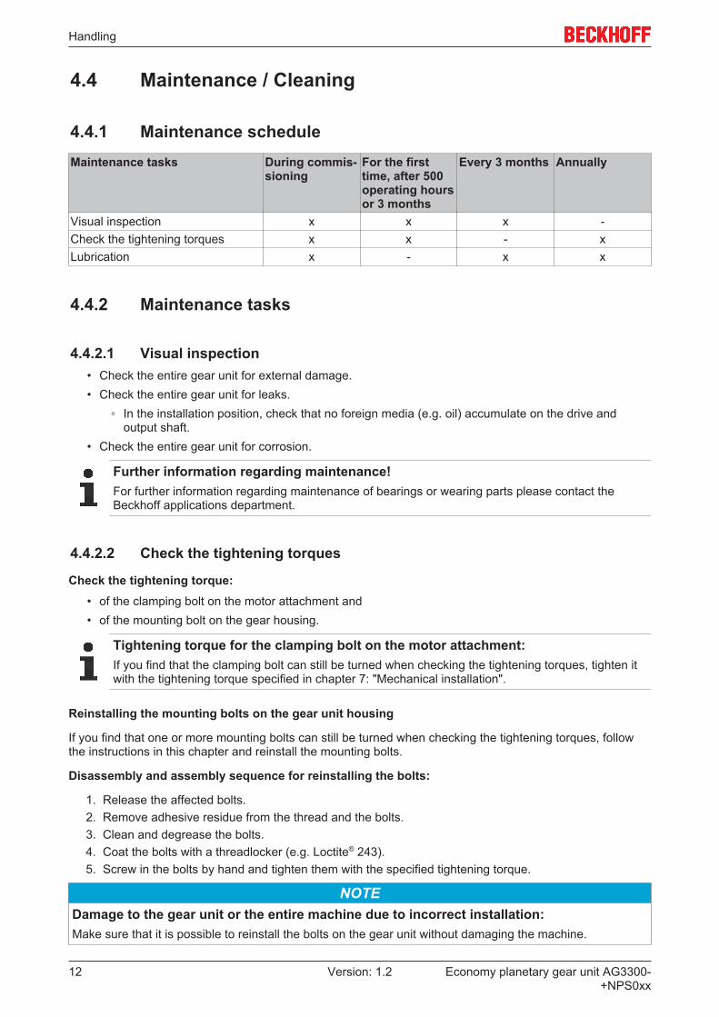
4.4.1 Maintenance scheduleMaintenance tasks During commis-
sioningFor the firsttime, after 500operating hoursor 3 months
Every 3 months Annually
Visual inspection x x x -Check the tightening torques x x - xLubrication x - x x
4.4.2 Maintenance tasks
4.4.2.1 Visual inspection• Check the entire gear unit for external damage.• Check the entire gear unit for leaks.
◦ In the installation position, check that no foreign media (e.g. oil) accumulate on the drive andoutput shaft.
• Check the entire gear unit for corrosion.
Further information regarding maintenance!For further information regarding maintenance of bearings or wearing parts please contact theBeckhoff applications department.
4.4.2.2 Check the tightening torques
Check the tightening torque:• of the clamping bolt on the motor attachment and• of the mounting bolt on the gear housing.
Tightening torque for the clamping bolt on the motor attachment:If you find that the clamping bolt can still be turned when checking the tightening torques, tighten itwith the tightening torque specified in chapter 7: "Mechanical installation".
Reinstalling the mounting bolts on the gear unit housing
If you find that one or more mounting bolts can still be turned when checking the tightening torques, followthe instructions in this chapter and reinstall the mounting bolts.
Disassembly and assembly sequence for reinstalling the bolts:
1. Release the affected bolts.2. Remove adhesive residue from the thread and the bolts.3. Clean and degrease the bolts.4. Coat the bolts with a threadlocker (e.g. Loctite® 243).5. Screw in the bolts by hand and tighten them with the specified tightening torque.
NOTEDamage to the gear unit or the entire machine due to incorrect installation:Make sure that it is possible to reinstall the bolts on the gear unit without damaging the machine.

Handling
Economy planetary gear unit AG3300-+NPS0xx
13Version: 1.2
4.4.2.3 Lubrication
CAUTIONDamage to the gear unit due to overheating of the componentsInadequate lubrication of the components may lead to damage to the gear unit due to overheating.• Calculate the usable life of the lubricant used• Relubricate all relevant components as required
4.4.2.3.1 Notes on the lubricant used
Lubricant usedAll gear units are lubricated for life at the factory with a lithium soap grease based on mineral oil ora food-grade synthetic grease (hydrocarbon oil, aluminum complex soap) (see name plate). Allbearings are lubricated for life at the factory.
Further information on the lubricants is available directly from the manufacturer:
Standard lubricants Lubricants for the food industry (USDA-H1 regis-tered)
Castrol Industrie GmbH, MönchengladbachPhone: +49 2161 909-30
www.castrol.com
Klüber Lubrication München KG, MunichPhone: + 49 89 7876-0
www.klueber.com
4.4.3 Commissioning after maintenance• Clean the gear unit externally.• Attach all safety devices.• Perform a test run before releasing the gear unit again for operation.

Handling
Economy planetary gear unit AG3300-+NPS0xx
14 Version: 1.2
4.4.4 Cleaning agents and cleaning procedures
4.4.4.1 Important notes
Cleaning the gear unit!During operation, the pumping action of the gear unit can result in cleaning agent entering the inside of the gear unit. The gear unit may only be cleaned at standstill!
Unsuitable cleaning agents may cause corrosion!The gear unit may only be cleaned with commercial cleaning agents. The cleaning agents may befat-dissolving but must be non-aggressive! An overview of suitable cleaning agents can be found insection "Overview of materials [} 15]".
Damage to seals!Cleaning the gear unit with a high-pressure water jet or a permanent present medium may damagethe gear seals.• Use a water jet with a maximum pressure of 28 bar.• Removal media from the seal within 30 minutes.
Residue-free cleaningRoughened surfaces cannot be cleaned without residues!• Avoid scratching the gear unit or damaging the surface. It may no longer be possible to guaran-
tee the effect of the HD design! Bacteria or similar matter may attach themselves to the surface!
Handling
Economy planetary gear unit AG3300-+NPS0xx
15Version: 1.2
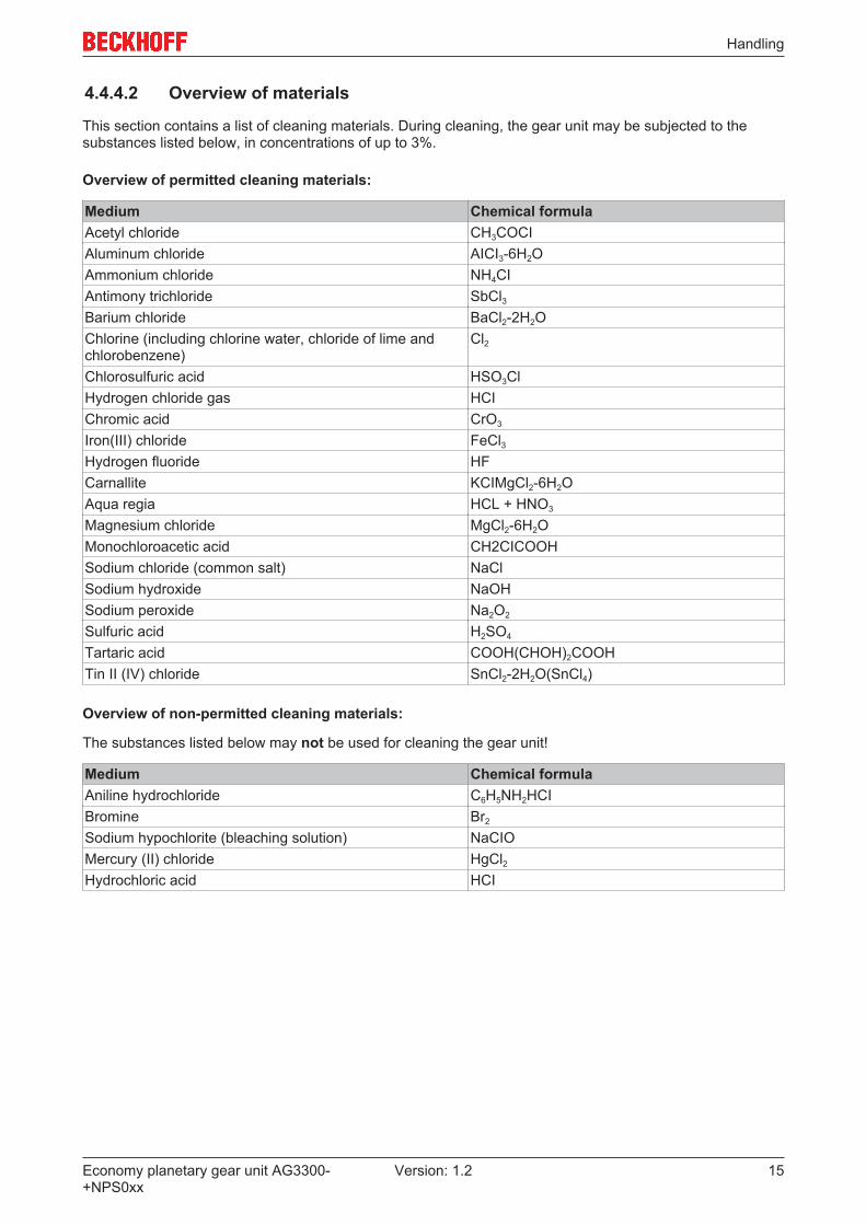
4.4.4.2 Overview of materials
This section contains a list of cleaning materials. During cleaning, the gear unit may be subjected to thesubstances listed below, in concentrations of up to 3%.
Overview of permitted cleaning materials:
Medium Chemical formulaAcetyl chloride CH3COCIAluminum chloride AICI3-6H2OAmmonium chloride NH4CIAntimony trichloride SbCl3Barium chloride BaCl2-2H2OChlorine (including chlorine water, chloride of lime andchlorobenzene)
Cl2
Chlorosulfuric acid HSO3ClHydrogen chloride gas HCIChromic acid CrO3
Iron(III) chloride FeCl3Hydrogen fluoride HFCarnallite KCIMgCl2-6H2OAqua regia HCL + HNO3
Magnesium chloride MgCl2-6H2OMonochloroacetic acid CH2CICOOHSodium chloride (common salt) NaClSodium hydroxide NaOHSodium peroxide Na2O2
Sulfuric acid H2SO4
Tartaric acid COOH(CHOH)2COOHTin II (IV) chloride SnCl2-2H2O(SnCl4)
Overview of non-permitted cleaning materials:
The substances listed below may not be used for cleaning the gear unit!
Medium Chemical formulaAniline hydrochloride C6H5NH2HCIBromine Br2
Sodium hypochlorite (bleaching solution) NaCIOMercury (II) chloride HgCl2Hydrochloric acid HCI
Handling
Economy planetary gear unit AG3300-+NPS0xx
16 Version: 1.2
4.5 DisposalNational regulationsObserve the relevant national disposal regulations.
Supplementary information on replacing the adapter plate and disassembly and disposal of the gear unit isavailable from our service department:
• The device should be disposed of by a certified disposal company. Addresses can be obtained fromour service department.
• Metal parts can be sent for metal recycling.
In accordance with the WEEE 2012/96/EC Directives we take old devices and accessories back forprofessional disposal, provided the transport costs are taken over by the sender. Send the devices with thenote “For disposal” to:
Beckhoff Automation GmbH & Co. KGHülshorstweg 2033415 Verl, Germany

Product overview
Economy planetary gear unit AG3300-+NPS0xx
17Version: 1.2
5 Product overview
5.1 Scope of supply AG3300• Check the completeness of the delivery against the delivery note.• Missing parts or damage should be reported immediately in writing to the carrier, the insurance
company and / or Beckhoff Automation.
5.2 Name plate AG3300
Number Explanation1 Type code2 Lubrication3 Motor4 Transmission ratio5 Barcode6 Country of manufacture7 Date of manufacture8 Serial number
Product overview
Economy planetary gear unit AG3300-+NPS0xx
18 Version: 1.2
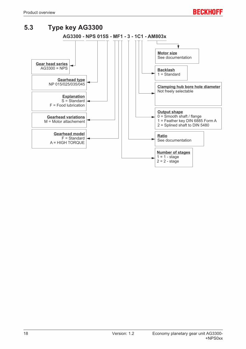
5.3 Type key AG3300

Technical description
Economy planetary gear unit AG3300-+NPS0xx
19Version: 1.2
6 Technical description
6.1 Gear unit configurationGear units of the AG3300-+NPSxxx series are single- or multi-stage, low-backlash planetary gear units. Thegear unit series is manufactured as version "M" (motor mounting) and can be used in any installationposition. The output shaft bearing is designed for high breakdown torques and high axial forces. Motorcentering via the clamping hub with bearing prevents radial distortion of the motor. The gear unit can beadapted to different motor types using an adapter flange and a spacer sleeve. The gear units aremanufactured to the ISO 9001 quality standard and lubricated for life.
6.2 Overview of gear componentsTechnical drawing Pos. Gear components
A
B
C
D
A Gear housingB Output shaftC Adapter plateD Through-holes (see chapter: Mechanical installation)
6.3 General technical dataThe maximum permissible speeds and torques can be found in our catalog or on our website athttp://www.beckhoff.de.
6.3.1 WeightThe table below shows the gear unit weights with a standard adapter flange. If a different adapter flange isused, the weight of the gear unit may differ by up to 30%.
Gear size AG3300-+NPS 015 025 035 0451–stage (in kg) 1.8 3.6 9.0 18.72–stage (in kg) 1.9 3.9 9.4 21.9

Mechanical installation
Economy planetary gear unit AG3300-+NPS0xx
20 Version: 1.2
7 Mechanical installation
7.1 Important notesThe gear unit can be used in any installation position.
NOTEAssembly sequenceAlways follow the assembly sequence described below in order to avoid damage.
The fastening screws are not included and must be provided by the customer. Pertinent information can befound in the individual assembly steps.
NOTECompressed air may damage gear unit seals.Do not use compressed air for cleaning the gear unit.
NOTEIn rare cases, leaks ("sweating") may occur at the drive in gear units with grease lubrication (see name plate).• To avoid "sweating", we recommend sealing the areas between
ð adapter plate and drive housing (gear unit) and
ð adapter plate and motor
ð with a surface seal adhesive (e.g. Loctite® 573 or 574).
ð For further information please contact Beckhoff Service.
Before the installation, make sure that the motor you select meets the requirements for the intended use.
Clean / degrease the following components with a clean, lint-free cloth and a grease-dissolving, non-aggressive cleaning agent. Further information can be found in chapter "Cleaning agents and cleaningprocedures":
• all surfaces in contact with adjacent components• Centering• the motor shaft• the internal diameter of the clamping hub• the spacer sleeve inside and outside
In addition, check the contact surfaces for damage and foreign particles.
7.2 Mounting the motor on the gear unitThe standard scope of supply of a AG3300-NPS0xx series planetary gear unit does not include a motor.
If a motor is to be mounted on the gear unit it must:• be a B5 type• have a radial and axial run-out tolerance according to DIN EN 50347• and have a smooth shaft.

Mechanical installation
Economy planetary gear unit AG3300-+NPS0xx
21Version: 1.2
Instructions for mounting the motor on the gear unit
For mounting a gear unit at a motor, we recommend Beckhoff servomotors of theseries AM8000 and AM8500 (including fan version)
If a motor is included in the scope of supply, it is already mounted on delivery. No further installationis required.
NOTEObserve the safety instructions!Follow the information and safety instructions when mounting the gear unit on motor. Special safety instruc-tions can be found in this documentation in "Notes on the AG3300 planetary gear unit".
Infographic Assembly sequence
D
F
C1
BA
E
C
H
BECKHOFF
• Clean all components to ensure they are grease-free and check the motor and gear unit for damageprior to assembly.
• Mount the motor in vertical direction, if possible.Note: If the motor shaft has a feather key, remove it.Note: Insert a half wedge, if recommended by themanufacturer.• Remove the plug (A) from the mounting hole in the
adapter plate (B).• Turn the clamping hub (C) until the clamping screw
(H) is accessible via the mounting hole.• Release the clamping bolt (H) of the clamping hub
(C) by one turn.• Push the motor shaft into the clamping hub of the
gear unit (E).
Note: The maximum permitted axial forces must not be exceeded. The motor shaft must slide easily. If thisis not the case, the clamping screw (H) should be loosened further.Note: For certain motor shaft diameters and uses an additional slotted spacer sleeve has to be installed.The slot the spacer sleeve must align with the groove (if present) of the motor shaft.Note: There must be no gap between the motor (D) and the adapter plate (B).• Coat the four screws (F) with a threadlocker
(e.g. Loctite® 243).• Attach the motor (D) to the adapter plate (B) with the four screws (F). Tighten the bolts uniformly and
crosswise with increasing torque.• Tighten the clamping screw (H) of the clamping hub (C).• Push the plug (A) into the mounting hole of the adapter plate (B).• Please refer to the following table regarding the bolt sizes and the specified tightening torques.

Mechanical installation
Economy planetary gear unit AG3300-+NPS0xx
22 Version: 1.2
Additional information for fastening and installing the clamping bolt
Infographic Pos. NameH Clamping boltI Clamping ring [part of the clamping hub (C)]J Spacer sleeveK Grooved motor shaftL Smooth motor shaft
Internal clamp-ing hub dia.
Identifying let-ter
Clamping bolt(H) / DIN ISO 4762
WidthA/F [mm]
Tighteningtorque [Nm]
Strength 12.9
Max. axial forceclamping hub
[N]8 Z M3 2.5 2 709 A M3 2.5 2 70
11 B M4 3 4.1 7014 C M5 4 9.5 7016 D M6 5 14 15019 E M6 5 14 15024 G M8 6 35 22028 H M6 5 14 22032 I M10 8 79 30038 K M10 8 79 300
Identification of the tightening torque
C1
H
C
XX Nm
C
The value of the tightening torque (C1) for the clamping bolt(H) is punched onto the clamping hub (C)from above (see diagram on the left).

Mechanical installation
Economy planetary gear unit AG3300-+NPS0xx
23Version: 1.2
7.3 Mounting the gear unit at the machine
A
A
• The gear housing features four through-holes (A)for fastening to your machine.
Note: Thoroughly clean the output shaft, thecentering devices and the contact surfaces.• Coat the bolts with threadlocker (e.g. Loctite® 243).• Attach the gear unit to the machine with the
fastening screws through the through-holes.
Note: Ensure that the machine surface is as smooth as possible.Note: Attach the gear unit such that the screw plug points downwards and the name plate is legible.Note: Do not use washers or toothed washers
Fittings on the output side
The gear unit may be damaged by distortion!Distortion may occur during installation of the gear unit, which may damage the gear unit.• Mount gearwheels and toothed belt pulleys on the output shaft without using force.• Never use a reaming or hitting action for mounting!• Only use suitable tools for the installation!• Ensure that the static axial forces permitted for the output bearings are not exceeded.
• Seal possible clearances during mounting on the output side.
Note: Ensure that the surfaces of the mounting parts are as smooth as possible.
Note: Only use screw head seals and O-rings for sealing purposes.
Maximum permitted static axial forces
Gear sizeAG3300-+NPS
015 025 035 045
Fa max [N] 9250 10750 18500 31250
Supplementary information on attaching the gear unit to a machine
Gear sizeAG3300-+NPS
Pitch circle Ø [mm] Hole dia.[mm]
Screw size / strength class
Tightening torque[Nm]
015 68 5.5 M5 / 12.9 9.0025 85 6.6 M6 / 12.9 15.4035 120 9.0 M8 / 12.9 37.5045 165 11.0 M10 / 12.9 73.5
Mechanical installation
Economy planetary gear unit AG3300-+NPS0xx
24 Version: 1.2
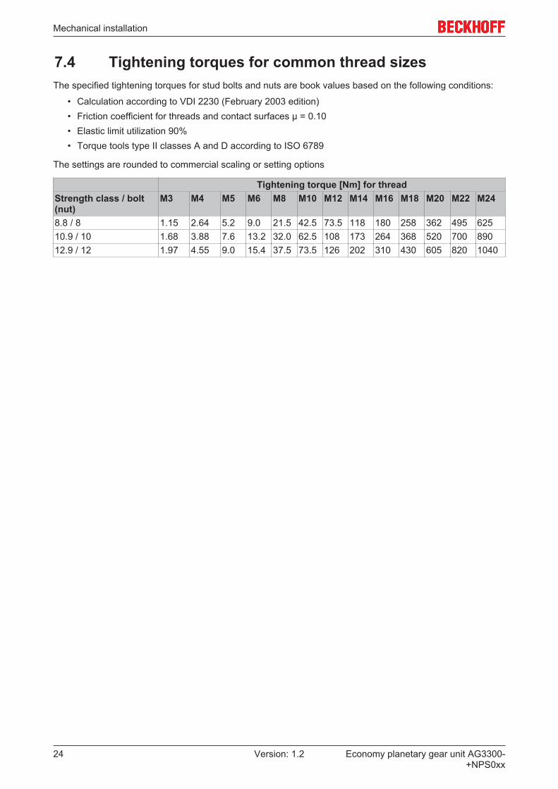
7.4 Tightening torques for common thread sizesThe specified tightening torques for stud bolts and nuts are book values based on the following conditions:
• Calculation according to VDI 2230 (February 2003 edition)• Friction coefficient for threads and contact surfaces µ = 0.10• Elastic limit utilization 90%• Torque tools type II classes A and D according to ISO 6789
The settings are rounded to commercial scaling or setting options
Tightening torque [Nm] for threadStrength class / bolt(nut)
M3 M4 M5 M6 M8 M10 M12 M14 M16 M18 M20 M22 M24
8.8 / 8 1.15 2.64 5.2 9.0 21.5 42.5 73.5 118 180 258 362 495 62510.9 / 10 1.68 3.88 7.6 13.2 32.0 62.5 108 173 264 368 520 700 89012.9 / 12 1.97 4.55 9.0 15.4 37.5 73.5 126 202 310 430 605 820 1040

Technical data
Economy planetary gear unit AG3300-+NPS0xx
25Version: 1.2
8 Technical dataDefinitionEquivalent force on the output (F2_eq) The equivalent force on the output (F2_eq) describes
the force that is relevant for dimensioning the gearunit.
Equivalent application torque (T2_eq) The equivalent application torque (T2_eq) describesthe for torque that is relevant for dimensioning thegear unit.
Dimensioning factor (fa) The dimensioning factor (fa) describes the influenceof the daily operating time and the operating factor onthe application torque.
Operating mode factor (KM) The operating mode factor (KM) describes theinfluence of duty cycle, number of cycles anddynamics on the application torque.
Mass moment of inertia (based on the drive) The mass moment of inertia J is a measure for thetendency of a body to maintain its motion state(whether at rest or in motion).
Running noise (LPA) Low running noise (LPA) of an application is becomingincreasingly important for environmental and healthreasons. The gear ratio and speed affect the runningnoise.In general, the following rule applies:Higher speed = higher running noiseHigher gear ratio = lower running noise
Max. radial force (F2R) The radial force (F2R) is the force component that actsat right angles to the output shaft or parallel to theoutput flange. It acts perpendicular to the axial forceand can have an axial distance x2 to the shaftshoulder or the shaft flange. This distance acts aslever arm. The lateral force generates a bendingmoment.
Max. torque at the output (T2a) (T2a) represents the maximum torque that can betransferred by the gear unit. This value may be lower,depending on application-specific boundaryconditions.
EMERGENCY STOP torque (T2Em.stop) The EMERGENCY STOP torque (T2Em.stop) is themaximum permitted torque at the gear unit output. Itmay be reached up to 1000 times during the servicelife of the gear unit and must never be exceeded.
Maximum drive speed (n1max) and permitted mean drive speed (n1N)
The two speeds that are relevant for gear unit dimensioning are the maximum and the rated speed at thedrive. The maximum permitted speed (n1max) must not be exceeded. Cycle operation is dimensioned basedon this value.
The permitted mean drive speed (n1N) must not be exceeded during continuous operation. The rated speedis limited by the housing temperature, which may not exceed 90 °C. The value specified in the technical dataapplies at an ambient temperature of + 20 °C.
This means: For higher ambient temperatures the rated input speed must be reduced.
Technical data
Economy planetary gear unit AG3300-+NPS0xx
26 Version: 1.2
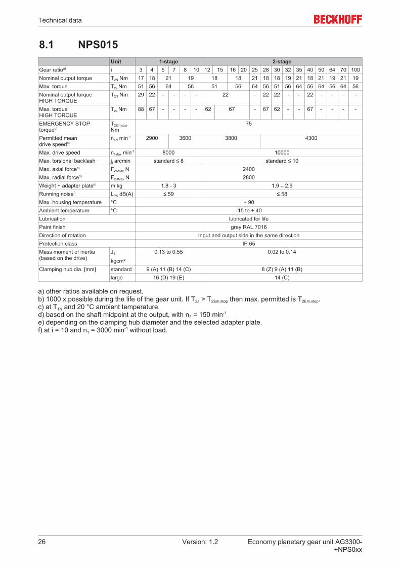
8.1 NPS015Unit 1-stage 2-stage
Gear ratioa) i 3 4 5 7 8 10 12 15 16 20 25 28 30 32 35 40 50 64 70 100Nominal output torque T2N Nm 17 18 21 19 18 18 21 18 18 19 21 18 21 19 21 19Max. torque T2a Nm 51 56 64 56 51 56 64 56 51 56 64 56 64 56 64 56Nominal output torqueHIGH TORQUE
T2N Nm 29 22 - - - - 22 - 22 22 - - 22 - - - -
Max. torqueHIGH TORQUE
T2a Nm 88 67 - - - - 62 67 - 67 62 - - 67 - - - -
EMERGENCY STOPtorqueb)
T2Em.stopNm
75
Permitted mean drive speedc)
n1N min-1 2900 3600 3800 4300
Max. drive speed n1Max min-1 8000 10000Max. torsional backlash jt arcmin standard ≤ 8 standard ≤ 10Max. axial forced) F2AMax N 2400Max. radial forced) F2RMax N 2800Weight + adapter platee) m kg 1.8 - 3 1.9 – 2.9Running noisef) LPA dB(A) ≤ 59 ≤ 58Max. housing temperature °C + 90Ambient temperature °C -15 to + 40Lubrication lubricated for lifePaint finish grey RAL 7016Direction of rotation Input and output side in the same directionProtection class IP 65Mass moment of inertia (based on the drive)
J1
kgcm²
0.13 to 0.55 0.02 to 0.14
Clamping hub dia. [mm] standard 9 (A) 11 (B) 14 (C) 8 (Z) 9 (A) 11 (B)large 16 (D) 19 (E) 14 (C)
a) other ratios available on request.b) 1000 x possible during the life of the gear unit. If T2a > T2Em.stop then max. permitted is T2Em.stop.c) at T1N and 20 °C ambient temperature.d) based on the shaft midpoint at the output, with n2 = 150 min-1
e) depending on the clamping hub diameter and the selected adapter plate.f) at i = 10 and n1 = 3000 min-1 without load.

Technical data
Economy planetary gear unit AG3300-+NPS0xx
27Version: 1.2
8.1.1 Dimension drawing NPS015

Technical data
Economy planetary gear unit AG3300-+NPS0xx
28 Version: 1.2
8.2 NPS025Unit 1-stage
Gear ratioa) i 3 4 5 7 8 10Nominal output torque T2N Nm 40 48 50 45Max. torque T2a Nm 128 152 160 144Nominal output torqueHIGH TORQUE
T2N Nm 63 58 -
Max. torqueHIGH TORQUE
T2a Nm 200 184 -
EMERGENCY STOPtorqueb)
T2Em.stop Nm 190
Permitted mean drive speedc)
n1N min-1 2700 2900
Max. drive speed n1Max min-1 7000Max. torsional backlash jt arcmin standard ≤ 8Max. axial forced) F2AMax N 3350Max. radial forced) F2RMax N 4200Weight + adapter platee) m kg 3.6 – 5.9Running noisef) LPA dB(A) ≤ 61Max. housing temperature °C + 90Ambient temperature °C -15 to + 40Lubrication lubricated for lifePaint finish grey RAL 7016Direction of rotation Input and output side in the same directionProtection class IP 65Mass moment of inertia (based on the drive)
J1 kgcm² 0.26 to 1.8
Clamping hub dia. [mm] standard 14 (C) 16 (D) 19 (E)large 24 (G) 28 (H)
a) other ratios available on request.b) 1000 x possible during the life of the gear unit. If T2a > T2Em.stop then max. permitted is T2Em.stop.c) at T1N and 20 °C ambient temperature.d) based on the shaft midpoint at the output, with n2 = 150 min-1
e) depending on the clamping hub diameter and the selected adapter plate.f) at i = 10 and n1 = 3000 min-1 without load.
Technical data
Economy planetary gear unit AG3300-+NPS0xx
29Version: 1.2
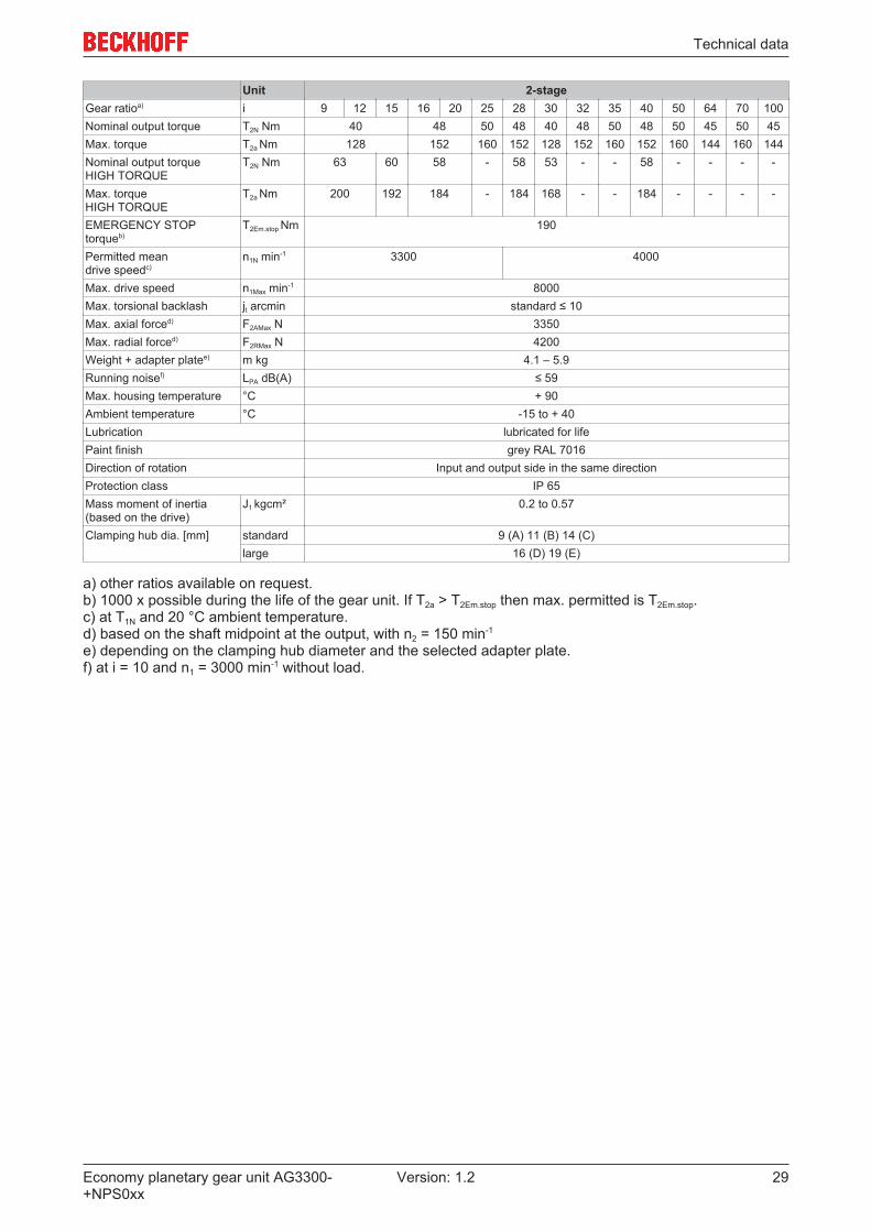
Unit 2-stageGear ratioa) i 9 12 15 16 20 25 28 30 32 35 40 50 64 70 100Nominal output torque T2N Nm 40 48 50 48 40 48 50 48 50 45 50 45Max. torque T2a Nm 128 152 160 152 128 152 160 152 160 144 160 144Nominal output torqueHIGH TORQUE
T2N Nm 63 60 58 - 58 53 - - 58 - - - -
Max. torqueHIGH TORQUE
T2a Nm 200 192 184 - 184 168 - - 184 - - - -
EMERGENCY STOPtorqueb)
T2Em.stop Nm 190
Permitted mean drive speedc)
n1N min-1 3300 4000
Max. drive speed n1Max min-1 8000Max. torsional backlash jt arcmin standard ≤ 10Max. axial forced) F2AMax N 3350Max. radial forced) F2RMax N 4200Weight + adapter platee) m kg 4.1 – 5.9Running noisef) LPA dB(A) ≤ 59Max. housing temperature °C + 90Ambient temperature °C -15 to + 40Lubrication lubricated for lifePaint finish grey RAL 7016Direction of rotation Input and output side in the same directionProtection class IP 65Mass moment of inertia (based on the drive)
J1 kgcm² 0.2 to 0.57
Clamping hub dia. [mm] standard 9 (A) 11 (B) 14 (C)large 16 (D) 19 (E)
a) other ratios available on request.b) 1000 x possible during the life of the gear unit. If T2a > T2Em.stop then max. permitted is T2Em.stop.c) at T1N and 20 °C ambient temperature.d) based on the shaft midpoint at the output, with n2 = 150 min-1
e) depending on the clamping hub diameter and the selected adapter plate.f) at i = 10 and n1 = 3000 min-1 without load.
Technical data
Economy planetary gear unit AG3300-+NPS0xx
30 Version: 1.2
8.2.1 Dimension drawing NPS025
Technical data
Economy planetary gear unit AG3300-+NPS0xx
31Version: 1.2
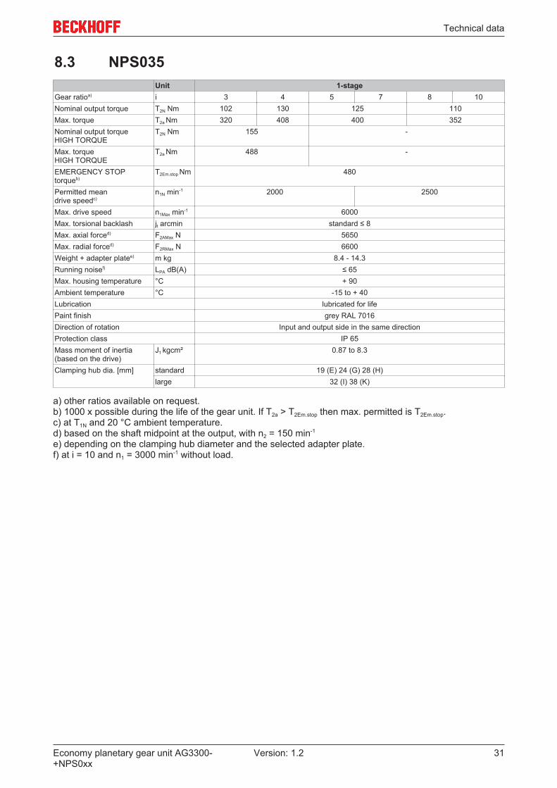
8.3 NPS035Unit 1-stage
Gear ratioa) i 3 4 5 7 8 10Nominal output torque T2N Nm 102 130 125 110Max. torque T2a Nm 320 408 400 352Nominal output torqueHIGH TORQUE
T2N Nm 155 -
Max. torqueHIGH TORQUE
T2a Nm 488 -
EMERGENCY STOPtorqueb)
T2Em.stop Nm 480
Permitted mean drive speedc)
n1N min-1 2000 2500
Max. drive speed n1Max min-1 6000Max. torsional backlash jt arcmin standard ≤ 8Max. axial forced) F2AMax N 5650Max. radial forced) F2RMax N 6600Weight + adapter platee) m kg 8.4 - 14.3Running noisef) LPA dB(A) ≤ 65Max. housing temperature °C + 90Ambient temperature °C -15 to + 40Lubrication lubricated for lifePaint finish grey RAL 7016Direction of rotation Input and output side in the same directionProtection class IP 65Mass moment of inertia (based on the drive)
J1 kgcm² 0.87 to 8.3
Clamping hub dia. [mm] standard 19 (E) 24 (G) 28 (H)large 32 (I) 38 (K)
a) other ratios available on request.b) 1000 x possible during the life of the gear unit. If T2a > T2Em.stop then max. permitted is T2Em.stop.c) at T1N and 20 °C ambient temperature.d) based on the shaft midpoint at the output, with n2 = 150 min-1
e) depending on the clamping hub diameter and the selected adapter plate.f) at i = 10 and n1 = 3000 min-1 without load.
Technical data
Economy planetary gear unit AG3300-+NPS0xx
32 Version: 1.2
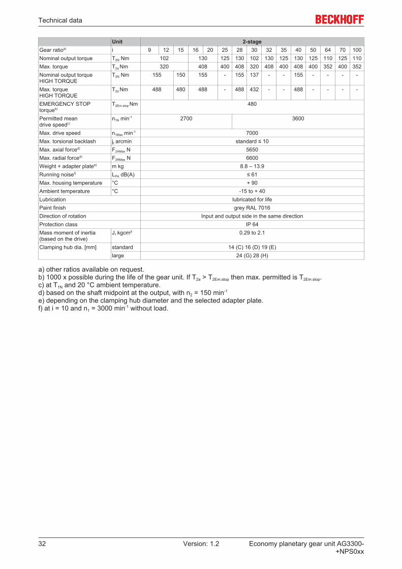
Unit 2-stageGear ratioa) i 9 12 15 16 20 25 28 30 32 35 40 50 64 70 100Nominal output torque T2N Nm 102 130 125 130 102 130 125 130 125 110 125 110Max. torque T2a Nm 320 408 400 408 320 408 400 408 400 352 400 352Nominal output torqueHIGH TORQUE
T2N Nm 155 150 155 - 155 137 - - 155 - - - -
Max. torqueHIGH TORQUE
T2a Nm 488 480 488 - 488 432 - - 488 - - - -
EMERGENCY STOPtorqueb)
T2Em.stop Nm 480
Permitted mean drive speedc)
n1N min-1 2700 3600
Max. drive speed n1Max min-1 7000Max. torsional backlash jt arcmin standard ≤ 10Max. axial forced) F2AMax N 5650Max. radial forced) F2RMax N 6600Weight + adapter platee) m kg 8.8 – 13.9Running noisef) LPA dB(A) ≤ 61Max. housing temperature °C + 90Ambient temperature °C -15 to + 40Lubrication lubricated for lifePaint finish grey RAL 7016Direction of rotation Input and output side in the same directionProtection class IP 64Mass moment of inertia (based on the drive)
J1 kgcm² 0.29 to 2.1
Clamping hub dia. [mm] standard 14 (C) 16 (D) 19 (E)large 24 (G) 28 (H)
a) other ratios available on request.b) 1000 x possible during the life of the gear unit. If T2a > T2Em.stop then max. permitted is T2Em.stop.c) at T1N and 20 °C ambient temperature.d) based on the shaft midpoint at the output, with n2 = 150 min-1
e) depending on the clamping hub diameter and the selected adapter plate.f) at i = 10 and n1 = 3000 min-1 without load.
Technical data
Economy planetary gear unit AG3300-+NPS0xx
33Version: 1.2
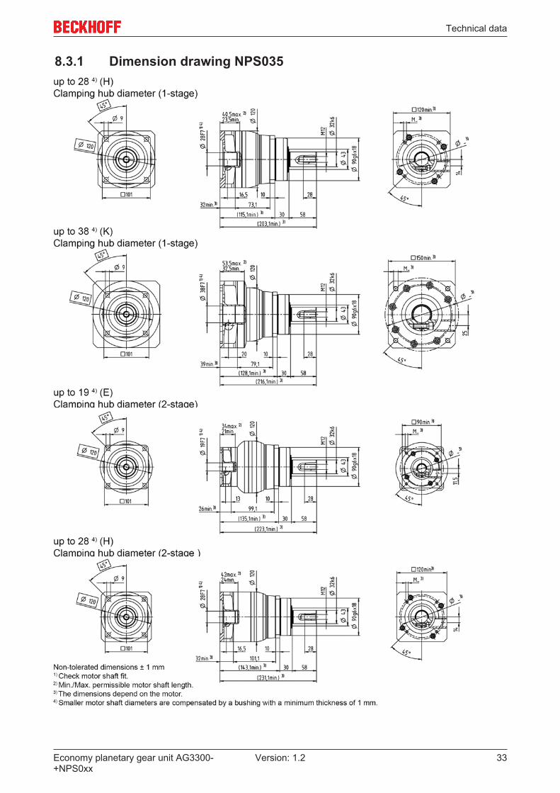
8.3.1 Dimension drawing NPS035

Technical data
Economy planetary gear unit AG3300-+NPS0xx
34 Version: 1.2
8.4 NPS045Unit 1-stage 2-stage
Gear ratioa) i 5 8 10 25 32 50 64 100Nominal output torque T2N Nm 350 200 350 200 350 200Max. torque T2a Nm 800 640 800 640 800 640EMERGENCY STOP torqueb) T2Em.stop Nm 1000Permitted mean drive speedc) n1N min-1 1800 2000 2600Max. drive speed n1Max min-1 4000 6000Max. torsional backlash jt arcmin standard ≤ 8 standard ≤ 10Max. axial forced) F2AMax N 9870Max. radial forced) F2RMax N 9900Weight including adapter platee) m kg 19 - 25 19 - 29Running noisef) LPA dB(A) ≤ 68 ≤ 65Max. permitted housingtemperature
°C + 90
Ambient temperature °C - 15 to + 40Lubrication lubricated for lifePaint finish grey RAL 7016Direction of rotation Input and output side in the same directionProtection class IP 64Mass moment of inertia (basedon the drive)
J1 kgcm² 7.2 to 8.7 1.6 to 7.5
Clamping hub dia. [mm] standard 38 (K) 19 (E) 24 (G) 28 (H)large - 32 (I) 38 (K)
a) other ratios available on request.b) 1000 x possible during the life of the gear unit. If T2a > T2Em.stop then max. permitted is T2Em.stop.c) at T1N and 20 °C ambient temperature.d) based on the shaft midpoint at the output, with n2 = 150 min-1
e) depending on the clamping hub diameter and the selected adapter plate.f) at i = 10 and n1 = 3000 min-1 without load.

Technical data
Economy planetary gear unit AG3300-+NPS0xx
35Version: 1.2
8.4.1 Dimension drawing NPS045

Commissioning
Economy planetary gear unit AG3300-+NPS0xx
36 Version: 1.2
9 Commissioning
9.1 Important notesNOTE
Improper operation may result in damage to the gear unit.• Please ensure that
ð the ambient temperature is not below -15 °C and not above +40 °C, and
ð the operating temperature does not exceed +90 °C.• Avoid icing, which can damage the seals.• For other operating conditions please contact our customer service.• Do not exceed the operational limit values for the gear unit• Only use the gear unit in a clean, dust-free and dry environment.
DANGERSerious risk of injury!• Only specialist personnel with extensive knowledge in the areas of
electrical engineering / drive technology are allowed to install and commission the equipment.• Check that all live connection points are protected against accidental contact. Dangerous voltages can
occur, up to 875 VDC.• The surface temperature of the motor can exceed 100 °C in operation. Check (measure) the tempera-
ture of the motor. Wait until the motor has cooled down below 40 °C before touching it.
• Make sure that, even if the drive starts to move unintentionally, no danger can result for personnel or machinery.
NOTEOverload of the gear unit!In the case of motor/gear unit combinations, the gear unit may be overloaded in the event of a fault (me-chanical blockage of the drivetrain) due to high gear ratios.To prevent this, make sure that the rated and peak motor torque is limited in the servo drive.Example:• Rated / peak motor torque: 1 Nm / 5 Nm• Rated / peak gear unit torque: 15 Nm / 24 Nm• Gear ratio: i = 10• The rated motor torque is not limited. The peak motor torque is limited to 2.4 Nm.
Commissioning
Economy planetary gear unit AG3300-+NPS0xx
37Version: 1.2
9.2 Guide for commissioning the gear unitsThe procedure for commissioning is described as an example.A different method may be appropriate or necessary, depending on the application of the equipment.
• Check the assembly and alignment of the motor and the gear unit.• Check the drive components such as clutch, gear unit, belt pulley and gear unit for correct seating and
setting (observe the permissible radial and axial forces).• Check the wiring and connections at the motor, servo drive and gear unit. Check that the earthing is
correct.• Test the function of the holding brake, if used. (Apply 24VDC, the brake must release).• Check whether the rotor of the motor revolves freely (release the brake, if necessary). Listen out for
grinding noises from the motor and the gear unit.• Check that all the required measures against accidental contact with live and moving parts have been
carried out.• Carry out any further checks which are specifically required for your system.• Now commission the drive according to the commissioning instructions for the servo drive.• In multi-axis systems, individually commission each drive unit (servo drive/motor(s)).• During the installation and commissioning look out for chips or similar contaminants that may penetrate
into the gear unit. Keep the work area clean and protect the gear unit from foreign objects. Penetrationof dirt reduces the service life of the gear unit.
Destruction of the gear unit due to excessively high motor torque!Before commissioning, check that your configured maximum motor torque does not destroy thegear unit. Further information can be found in chapter “Important notes [} 36]”.

Commissioning
Economy planetary gear unit AG3300-+NPS0xx
38 Version: 1.2
9.3 TroubleshootingNOTE
Changed operating behaviorA change in operating behavior may indicate existing damage of the gear unit or result in damage to the gear unit.• Do not recommission the gear unit until the fault has been rectified.
CAUTIONPersonal injuriesTroubleshooting may only be performed by trained personnel.
Error Possible cause RemedyIncreased operating temperature The gear unit is not suitable for the
purpose.Check the technical data.
Motor heats up the gear unit. Check the wiring of the motor.Ensure adequate cooling.Change the motor.
Ambient temperature too high. Ensure adequate cooling.Increased operating noises Distorted motor mounting Contact our service department.
Bearing damageGear tooth damageToothed belt tension too high
Lubricant loss Lubricant quantity too high Wipe off the leaking lubricant andcontinue to monitor the gear unit.Lubricant discharge should stopafter a short time.
Leaks Please contact Beckhoff Service.

Support and Service
Economy planetary gear unit AG3300-+NPS0xx
39Version: 1.2
10 Support and ServiceBeckhoff and their partners around the world offer comprehensive support and service, making available fastand competent assistance with all questions related to Beckhoff products and system solutions.
Beckhoff's branch offices and representatives
Please contact your Beckhoff branch office or representative for local support and service on Beckhoffproducts!
The addresses of Beckhoff's branch offices and representatives round the world can be found on her internetpages:http://www.beckhoff.com
You will also find further documentation for Beckhoff components there.
Beckhoff Headquarters
Beckhoff Automation GmbH & Co. KG
Huelshorstweg 2033415 VerlGermany
Phone: +49(0)5246/963-0Fax: +49(0)5246/963-198e-mail: [email protected]
Beckhoff Support
Support offers you comprehensive technical assistance, helping you not only with the application ofindividual Beckhoff products, but also with other, wide-ranging services:
• support• design, programming and commissioning of complex automation systems• and extensive training program for Beckhoff system components
Hotline: +49(0)5246/963-157Fax: +49(0)5246/963-9157e-mail: [email protected]
Beckhoff Service
The Beckhoff Service Center supports you in all matters of after-sales service:
• on-site service• repair service• spare parts service• hotline service
Hotline: +49(0)5246/963-460Fax: +49(0)5246/963-479e-mail: [email protected]