Earth Shack Report
36
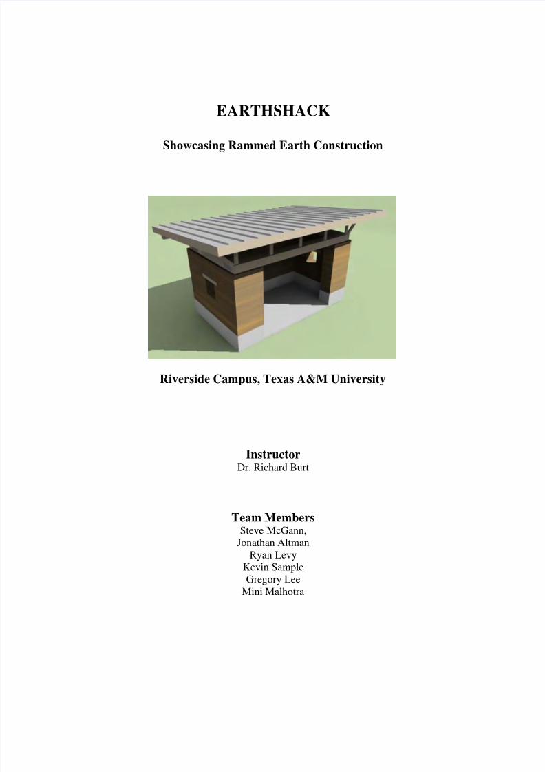
EARTHSHACK Showcasing Rammed Earth Construction Riverside Campus, Texas A&M University Instructor Dr. Richard Burt Team Members Steve McGann, Jonathan Altman Ryan Levy Kevin Sample Gregory Lee Mini Malhotra
-
Upload
jorge-alonso -
Category
Documents
-
view
226 -
download
0
Transcript of Earth Shack Report
8/6/2019 Earth Shack Report
http://slidepdf.com/reader/full/earth-shack-report 1/35
EARTHSHACK
Showcasing Rammed Earth Construction
Riverside Campus, Texas A&M University
InstructorDr. Richard Burt
Team MembersSteve McGann,
Jonathan AltmanRyan Levy
Kevin SampleGregory Lee
Mini Malhotra
8/6/2019 Earth Shack Report
http://slidepdf.com/reader/full/earth-shack-report 2/35
2
Table of Content
List of Tables .................................................................................................................................. 3
List of Figures ................................................................................................................................. 3
1. Introduction............................................................................................................................. 4
2. Construction technique ........................................................................................................... 6
3. Project planning ...................................................................................................................... 6
4. Materials ................................................................................................................................. 8
5. Soil characteristics .................................................................................................................. 9
6. Field tests .............................................................................................................................. 10
6.1. Jar test ........................................................................................................................... 106.2. Sausage test................................................................................................................... 10
6.3. Ball dropping test.......................................................................................................... 10
7. Formwork.............................................................................................................................. 12
8. On-site construction.............................................................................................................. 13
8.1. Wall structure................................................................................................................ 13
8.2. Window openings in the second lift.............................................................................. 17
8.3. Protection against the weather ...................................................................................... 20
8.4. Additional reinforcement in third lift............................................................................ 21
8.5. Bond beams over the wall structure.............................................................................. 22
8.6. Roof structure................................................................................................................ 23
9. Lessons learned..................................................................................................................... 24
References..................................................................................................................................... 27
APPENDIX A Details of Roof Truss Assembly .......................................................................... 28
APPENDIX B Details of Exterior Finish ..................................................................................... 33
APPENDIX C Time Sheet............................................................................................................ 34
8/6/2019 Earth Shack Report
http://slidepdf.com/reader/full/earth-shack-report 3/35
3
List of Tables
Table 1: Schedule of Activities....................................................................................................... 7
Table 2: Items and quantity estimates............................................................................................. 8
Table 3: Composition of soil........................................................................................................... 9
List of Figures
Figure 1: Location of the site.......................................................................................................... 4
Figure 2: Construction phases......................................................................................................... 5
Figure 3: Constituents of the soil .................................................................................................... 9
Figure 4: Field tests....................................................................................................................... 11
Figure 5: Formwork as designed................................................................................................... 12
Figure 6: Formwork as constructed for the first lift...................................................................... 12
Figure 7: Setting up formwork for the first lift (4/10) .................................................................. 14
Figure 8: Soil brought to the site (4/10)....................................................................................... 14
Figure 9: Erecting the first lift (4/12)............................................................................................ 14
Figure 10: Securing the first lift (4/12) ......................................................................................... 15
Figure 11: First lift form stripped (4/17)...................................................................................... 15
Figure 12: Left wall before and after trowelling (4/17)................................................................ 15
Figure 13: Preparing for the second lift after letting lift #1 dry out (4/17)................................... 16
Figure 14: Edges of the wall ......................................................................................................... 16
Figure 15: Window opening ......................................................................................................... 18
Figure 16: Formwork for the second lift (4/17) ............................................................................ 19
Figure 17: Early removal of the forms of the second lift (4/19)................................................. 19
Figure 18: Structure protected against the rain after the first and second lifts ............................. 20
Figure 19: Impact of thunderstorm (52mph) on different sides of the first lift ............................ 20
Figure 20: Third lift, with previous lifts protected at the back (4/24) .......................................... 20
Figure 21: Additional reinforcement ............................................................................................ 21
Figure 22: Placing and leveling the bond beams (5/5) ................................................................. 22
Figure 23: Stringers and joists (5/5).............................................................................................. 23
8/6/2019 Earth Shack Report
http://slidepdf.com/reader/full/earth-shack-report 4/35
4
1. Introduction
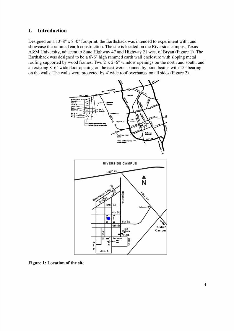
Designed on a 13'-8" x 8'-0" footprint, the Earthshack was intended to experiment with, andshowcase the rammed earth construction. The site is located on the Riverside campus, TexasA&M University, adjacent to State Highway 47 and Highway 21 west of Bryan (Figure 1). The
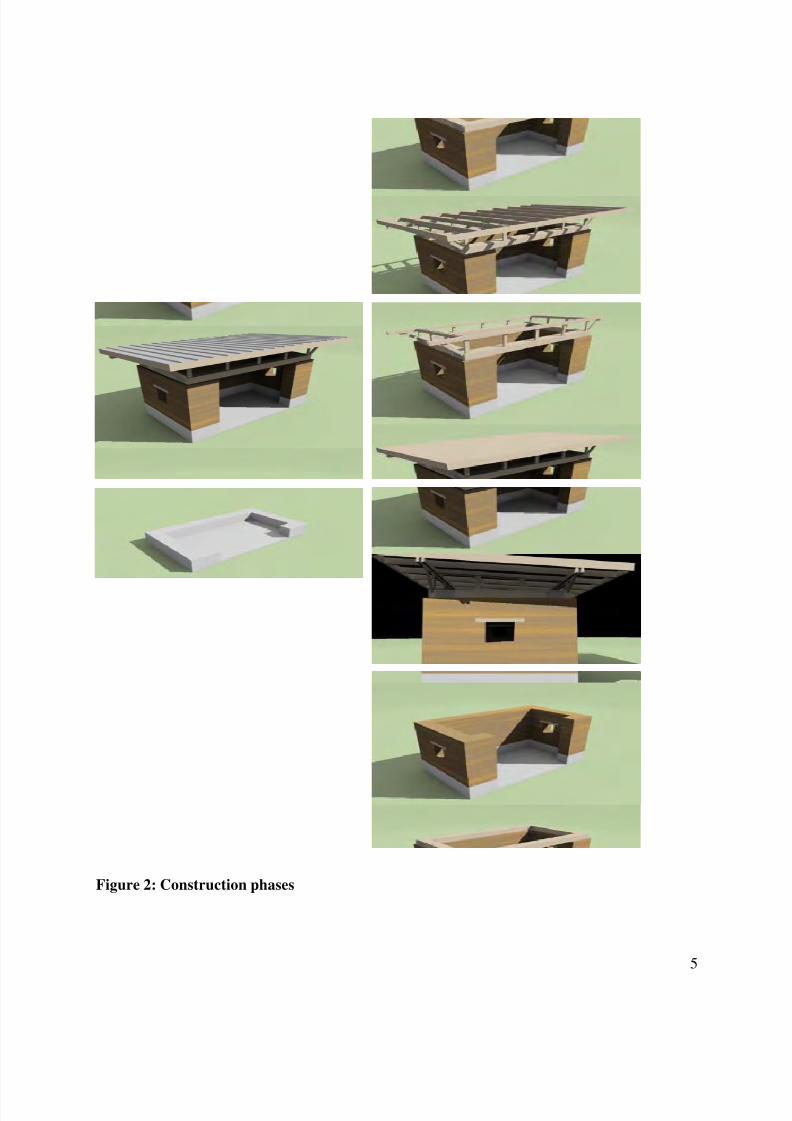
Earthshack was designed to be a 6'-6" high rammed earth wall enclosure with sloping metalroofing supported by wood frames. Two 2' x 2'-6" window openings on the north and south, andan existing 8'-6" wide door opening on the east were spanned by bond beams with 15” bearingon the walls. The walls were protected by 4' wide roof overhangs on all sides (Figure 2).
Figure 1: Location of the site
8/6/2019 Earth Shack Report
http://slidepdf.com/reader/full/earth-shack-report 5/35
5
Figure 2: Construction phases
8/6/2019 Earth Shack Report
http://slidepdf.com/reader/full/earth-shack-report 6/35
2. Construction technique
Rammed earth is a method of building walls whereby a mixture of earth is compacted in layersbetween forms. Each layer of earth is approximately 4 inches deep. As each form is filled andthe earth hardens, the formwork is removed and placed for the next lift, and the process
continues until the desired wall height is achieved. Forms can be stripped off as soon as theearth between the formwork is set, as the compressed earth wall is self-supporting immediately.The soil mix needs to be carefully balanced between clay, sand and aggregate. The clay andmoisture content of rammed earth is relatively low compared to that used for mud brick or otherearth building methods.
3. Project planning
The planning and execution was done in three phases that include: (1) design, quantity estimate,obtaining materials; (2) construction of formwork in the wood shop; and (3) on-site construction.
Figure 2 shows the on-site construction phases, which include: the concrete base, wall structure,bond beams, stringer and joists, and roofing.
The on-site activities were planned considering the weather, which is critical for drying of theconsecutive lifts. Curing or complete drying of the wall, which increases the compressivestrength of the wall, takes a period of time dependant on wall thickness, temperature, wind, andhumidity. The initial compressive strength should be adequate to allow construction of thesuccessive lifts. Rain and the wind direction were the other two factors that needed additionalconsideration, in this project.
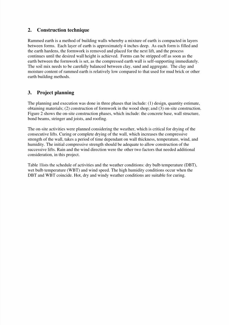
Table 1lists the schedule of activities and the weather conditions: dry bulb temperature (DBT),
wet bulb temperature (WBT) and wind speed. The high humidity conditions occur when theDBT and WBT coincide. Hot, dry and windy weather conditions are suitable for curing.
8/6/2019 Earth Shack Report
http://slidepdf.com/reader/full/earth-shack-report 7/35
7
Table 1: Schedule of Activities
Date Activity
Mon Mar-27 Scheduling, assignment of tasks
Tue Mar-28
Wed Mar-29 Design completedThu Mar-30 Quantity Estimation
Fri Mar-31 Form work design
Sat Apr-1
Sun Apr-2
Mon Apr-3 Final review of tasks
Tue Apr-4
Wed Apr-5
Thu Apr-6 Purchased construction materials
Fri Apr-7 Formwork Completed
Sat Apr-8
Sun Apr-9
Mon Apr-10 Placed formwork for first lift
Tue Apr-11
Wed Apr-12 Erected first liftThu Apr-13
Fri Apr-14
Sat Apr-15
Sun Apr-16
Mon Apr-17 Placed formwork for second lift
Tue Apr-18 Rammed second lift
Wed Apr-19 Removed inside formwork and replaced it back
Thu Apr-20
Fri Apr-21
Sat Apr-22
Sun Apr-23
Mon Apr-24 Placed formwork for third lift
Tue Apr-25
Wed Apr-26 Completed formwork for third liftThu Apr-27 Rammed third lift
Fri Apr-28
Sat Apr-29
Sun Apr-30
Mon May-1
Tue May-2
Wed May-3
Thu May-4
Fri May-5 Placed bond beams and stringers
Sat May-6
Sun May-7
Mon May-8
Tue May-9
Days with high humidity and/or precipitation
W e a t h er D
a t a ( M ar ch - A pr i l 2 0 0 6 )
0 2 0
4 0
6 0
8 0
1 0 0
3/273/28
3/293/303/314/14/24/34/44/54/64/74/84/9
4/104/11
4/124/134/144/154/164/174/184/194/204/214/224/234/244/25
4/264/274/284/294/305/15/25/35/45/55/65/75/85/9
5/105/115/12
Temperature (F)
0 1 0
2 0
3 0
4 0
5 0
Wind Speed (mph)
M ax .D B T
Mi n.D B T
A v g.D B T
A v g.
WB T
Wi n d S p e e d
8/6/2019 Earth Shack Report
http://slidepdf.com/reader/full/earth-shack-report 8/35
8
4. Materials
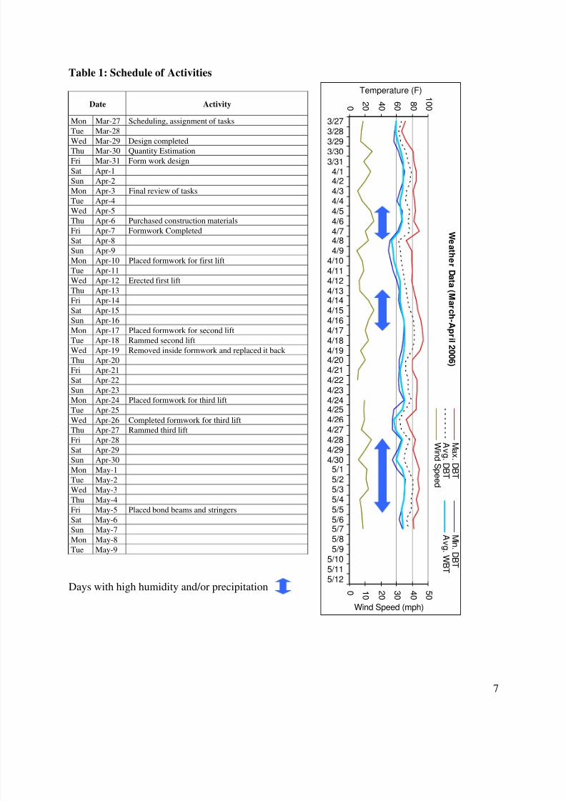
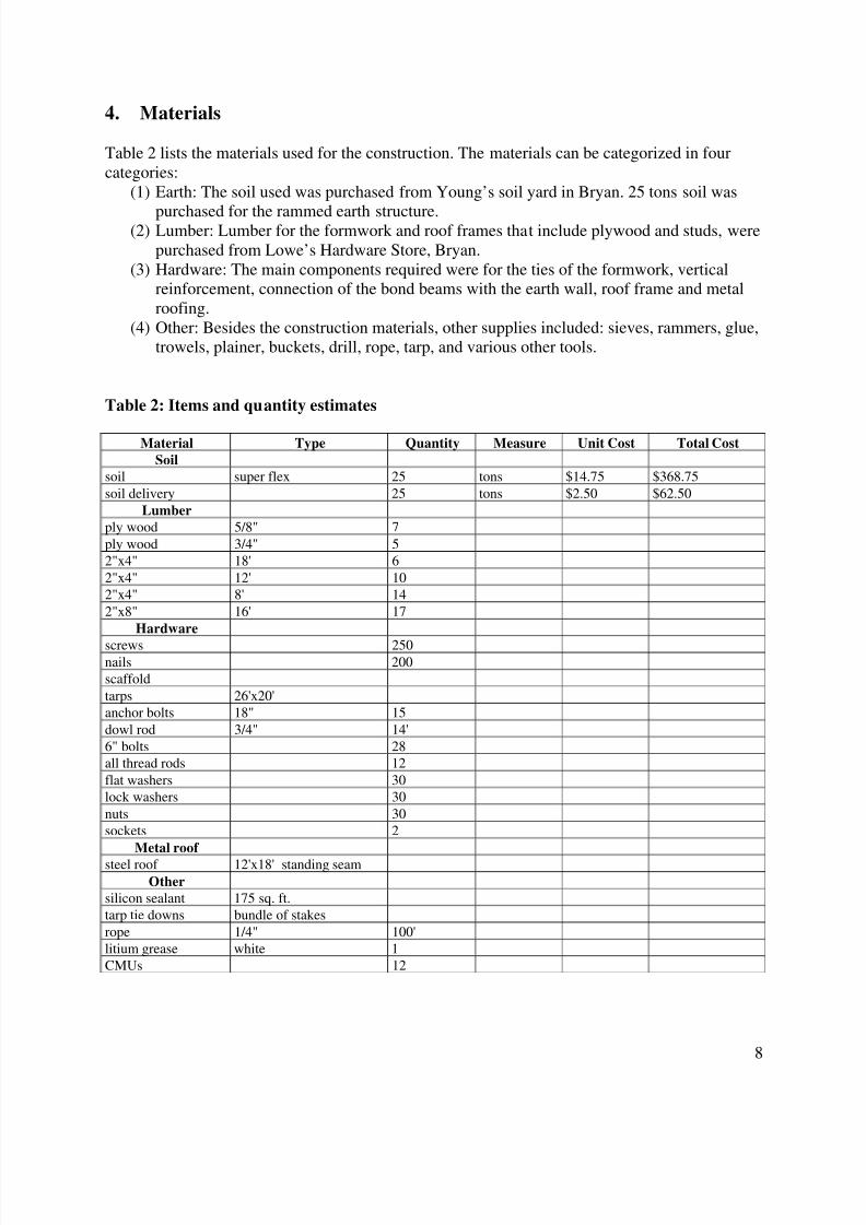
Table 2 lists the materials used for the construction. The materials can be categorized in fourcategories:
(1) Earth: The soil used was purchased from Young’s soil yard in Bryan. 25 tons soil was
purchased for the rammed earth structure.(2) Lumber: Lumber for the formwork and roof frames that include plywood and studs, were
purchased from Lowe’s Hardware Store, Bryan.(3) Hardware: The main components required were for the ties of the formwork, vertical
reinforcement, connection of the bond beams with the earth wall, roof frame and metalroofing.
(4) Other: Besides the construction materials, other supplies included: sieves, rammers, glue,trowels, plainer, buckets, drill, rope, tarp, and various other tools.
Table 2: Items and quantity estimates
Material Type Quantity Measure Unit Cost Total Cost
Soil
soil super flex 25 tons $14.75 $368.75
soil delivery 25 tons $2.50 $62.50
Lumber
ply wood 5/8" 7
ply wood 3/4" 5
2"x4" 18' 6
2"x4" 12' 10
2"x4" 8' 14
2"x8" 16' 17
Hardware
screws 250nails 200
scaffold
tarps 26'x20'
anchor bolts 18" 15
dowl rod 3/4" 14'
6" bolts 28
all thread rods 12
flat washers 30
lock washers 30
nuts 30
sockets 2
Metal roof
steel roof 12'x18' standing seam
Other
silicon sealant 175 sq. ft.
tarp tie downs bundle of stakes
rope 1/4" 100'
litium grease white 1
CMUs 12
8/6/2019 Earth Shack Report
http://slidepdf.com/reader/full/earth-shack-report 9/35
9
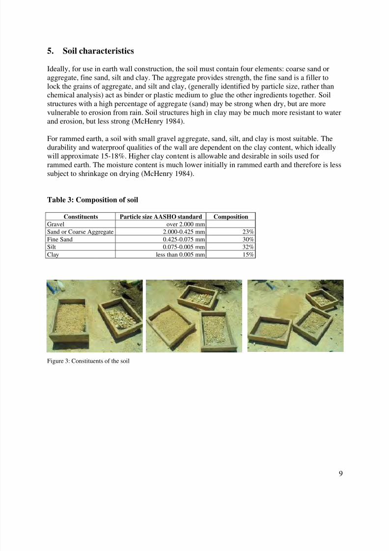
5. Soil characteristics
Ideally, for use in earth wall construction, the soil must contain four elements: coarse sand oraggregate, fine sand, silt and clay. The aggregate provides strength, the fine sand is a filler tolock the grains of aggregate, and silt and clay, (generally identified by particle size, rather than
chemical analysis) act as binder or plastic medium to glue the other ingredients together. Soilstructures with a high percentage of aggregate (sand) may be strong when dry, but are morevulnerable to erosion from rain. Soil structures high in clay may be much more resistant to waterand erosion, but less strong (McHenry 1984).
For rammed earth, a soil with small gravel aggregate, sand, silt, and clay is most suitable. Thedurability and waterproof qualities of the wall are dependent on the clay content, which ideallywill approximate 15-18%. Higher clay content is allowable and desirable in soils used forrammed earth. The moisture content is much lower initially in rammed earth and therefore is lesssubject to shrinkage on drying (McHenry 1984).
Table 3: Composition of soil
Constituents Particle size AASHO standard Composition
Gravel over 2.000 mm
Sand or Coarse Aggregate 2.000-0.425 mm 23%
Fine Sand 0.425-0.075 mm 30%
Silt 0.075-0.005 mm 32%
Clay less than 0.005 mm 15%
Figure 3: Constituents of the soil
8/6/2019 Earth Shack Report
http://slidepdf.com/reader/full/earth-shack-report 10/35
10
6. Field tests
For this project, the composition of the soil, and its suitability for the rammed earth constructionwas tested through various field tests.
6.1. Jar test
Simple field soil tests are made with a glass jar and water. The jar was partially filled with theavailable soil, and water is added above the soil level. The mixture was shaken and allowed tosettle until the water becomes clear. The resulting stratification with bands of coarse aggregatesat the bottom, sand, silt and clay on top indicated the proportions of various ingredients.
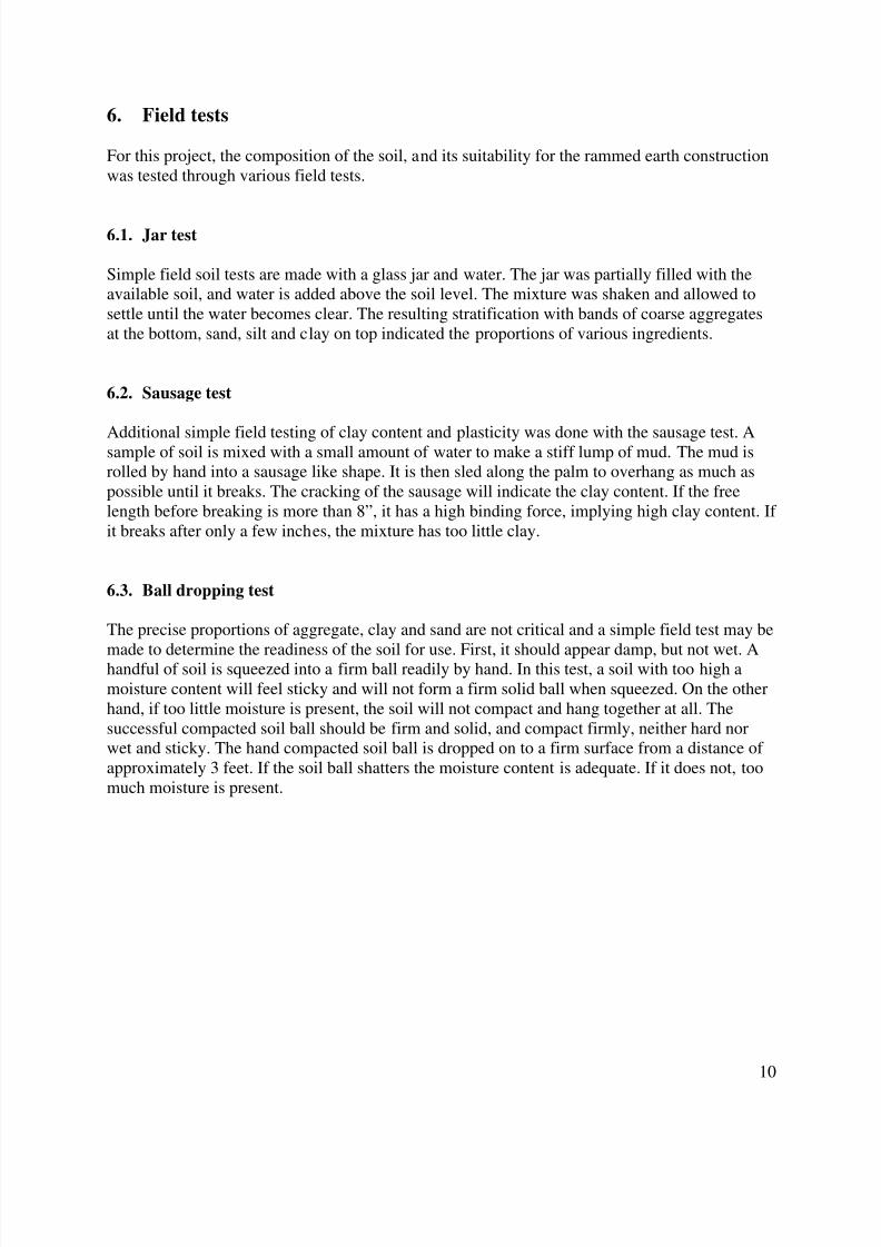
6.2. Sausage test
Additional simple field testing of clay content and plasticity was done with the sausage test. Asample of soil is mixed with a small amount of water to make a stiff lump of mud. The mud isrolled by hand into a sausage like shape. It is then sled along the palm to overhang as much aspossible until it breaks. The cracking of the sausage will indicate the clay content. If the freelength before breaking is more than 8”, it has a high binding force, implying high clay content. If it breaks after only a few inches, the mixture has too little clay.
6.3. Ball dropping test
The precise proportions of aggregate, clay and sand are not critical and a simple field test may be
made to determine the readiness of the soil for use. First, it should appear damp, but not wet. Ahandful of soil is squeezed into a firm ball readily by hand. In this test, a soil with too high amoisture content will feel sticky and will not form a firm solid ball when squeezed. On the otherhand, if too little moisture is present, the soil will not compact and hang together at all. Thesuccessful compacted soil ball should be firm and solid, and compact firmly, neither hard norwet and sticky. The hand compacted soil ball is dropped on to a firm surface from a distance of approximately 3 feet. If the soil ball shatters the moisture content is adequate. If it does not, toomuch moisture is present.
8/6/2019 Earth Shack Report
http://slidepdf.com/reader/full/earth-shack-report 11/35
11
Soil ball test: a shatter soil ball indicates that the properamount of moisture is present
Sausage test Jar test
Figure 4: Field tests
8/6/2019 Earth Shack Report
http://slidepdf.com/reader/full/earth-shack-report 12/35
12
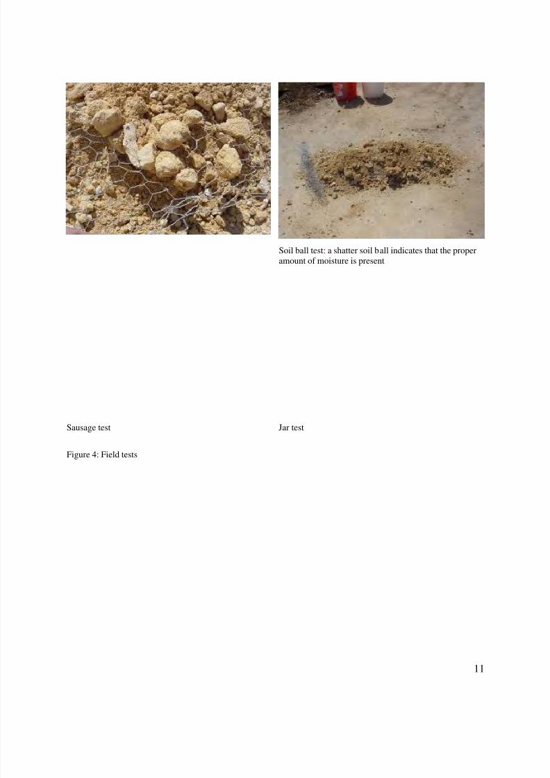
7. Formwork
The forms were made using 8’x4’ sheets of 5/8” thick plywood. These boards were cut into three2’-8” high pieces, in order to achieve a 2’ high lift with 4” to 8” overlap over the base/previouslift. 2 x 4 studs were attached to the boards horizontally to provide lateral strengthen and were
extended for at least 4”-5” on both sides of the board to connect the adjoining boards using bolts.Forms were prepared in architecture woodshop, and was brought to and erected on site.
Figure 5: Formwork as designed
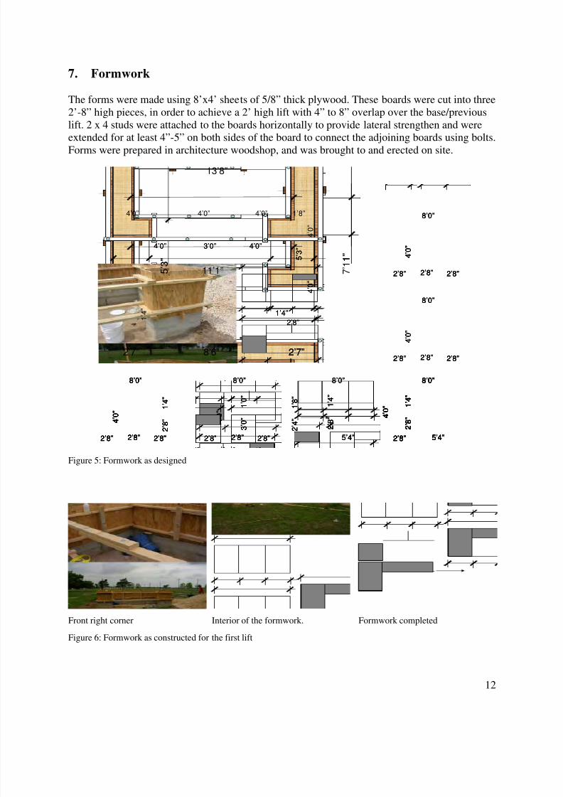
Front right corner Interior of the formwork. Formwork completed
Figure 6: Formwork as constructed for the first lift
2’8” 2’8” 2’8”
4 ’ 0 ”
8’0”
2’8” 5’4”
2 ’ 8 ”
1 ’ 4 ”
8’0”
4 ’ 0 ”
2’8” 5’4”
2 ’ 8 ”
1 ’ 4 ”
8’0”
2 ’ 4 ”
1 ’ 8 ”
2’8” 2’8” 2’8”
4 ’ 0 ”
8’0”
3 ’ 0 ”
1 ’ 0 ”
2’8” 2’8” 2’8”
4 ’ 0 ”
8’0”
2’8” 5’4”
2 ’ 8 ”
1 ’ 4 ”
8’0”
4 ’ 0 ”
2’8” 2’8” 2’8”
4 ’ 0 ”
8’0”
2 ’ 8 ”
1 ’ 4 ”
4 ’ 0 ”
4 ’ 0 ”
2’8”
5 ’ 3 ”
1’4” 1 ’ 4 ”
4’0”4’0” 3’0”
4’0”4’0” 1’8”4’0”
13’8”
7 ’ 1 1 ”
5 ’ 3 ”
2’7” 2’7”8’6”
11’1” 2’8” 2’8” 2’8”
4 ’ 0 ”
8’0”
2’8” 2’8” 2’8”
4 ’ 0 ”
8’0”
2’8” 5’4”
2 ’ 8 ”
1 ’ 4 ”
8’0”
4 ’ 0 ”
2’8” 5’4”
2 ’ 8 ”
1 ’ 4 ”
8’0”
4 ’ 0 ”
2’8” 5’4”
2 ’ 8 ”
1 ’ 4 ”
8’0”
2 ’ 4 ”
1 ’ 8 ”
2’8” 5’4”
2 ’ 8 ”
1 ’ 4 ”
8’0”
2 ’ 4 ”
1 ’ 8 ”
2’8” 2’8” 2’8”
4 ’ 0 ”
8’0”
3 ’ 0 ”
1 ’ 0 ”
2’8” 2’8” 2’8”
4 ’ 0 ”
8’0”
3 ’ 0 ”
1 ’ 0 ”
2’8” 2’8” 2’8”
4 ’ 0 ”
8’0”
2’8” 2’8” 2’8”
4 ’ 0 ”
8’0”
2’8” 5’4”
2 ’ 8 ”
1 ’ 4 ”
8’0”
4 ’ 0 ”
2’8” 5’4”
2 ’ 8 ”
1 ’ 4 ”
8’0”
4 ’ 0 ”
2’8” 2’8” 2’8”
4 ’ 0 ”
8’0”
2 ’ 8 ”
1 ’ 4 ”
2’8” 2’8” 2’8”
4 ’ 0 ”
8’0”
2’8” 2’8” 2’8”
4 ’ 0 ”
8’0”
2 ’ 8 ”
1 ’ 4 ”
4 ’ 0 ”
4 ’ 0 ”
2’8”
5 ’ 3 ”
1’4” 1 ’ 4 ”
4’0”4’0” 3’0”
4’0”4’0” 1’8”4’0”
13’8”
7 ’ 1 1 ”
5 ’ 3 ”
2’7” 2’7”8’6”
11’1”
8/6/2019 Earth Shack Report
http://slidepdf.com/reader/full/earth-shack-report 13/35
13
8. On-site construction
8.1. Wall structure
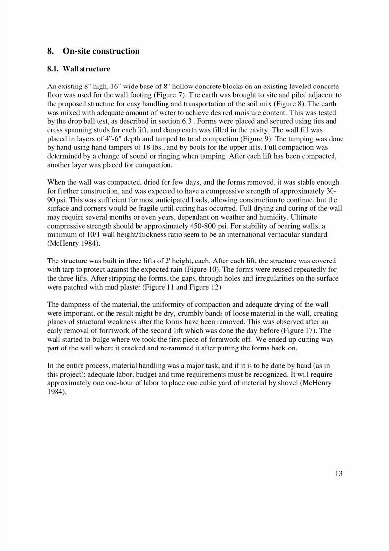
An existing 8" high, 16" wide base of 8" hollow concrete blocks on an existing leveled concrete
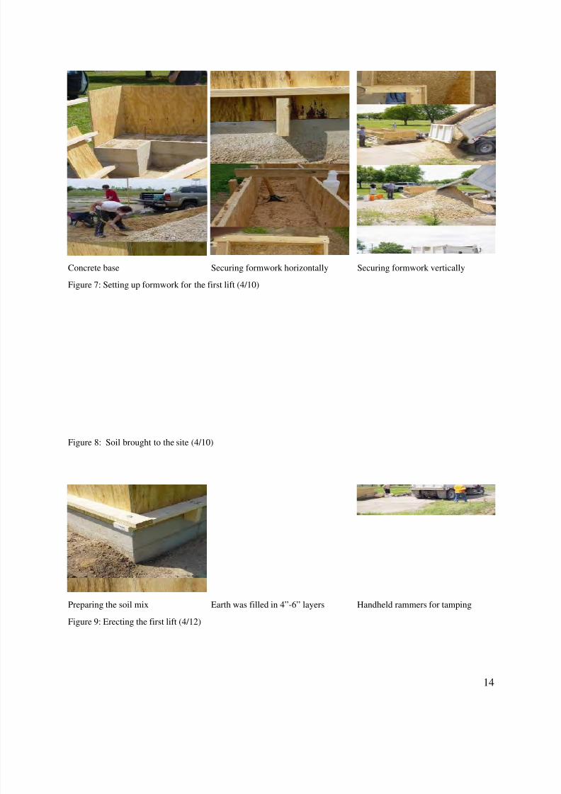
floor was used for the wall footing (Figure 7). The earth was brought to site and piled adjacent tothe proposed structure for easy handling and transportation of the soil mix (Figure 8). The earthwas mixed with adequate amount of water to achieve desired moisture content. This was testedby the drop ball test, as described in section 6.3 . Forms were placed and secured using ties andcross spanning studs for each lift, and damp earth was filled in the cavity. The wall fill wasplaced in layers of 4”-6" depth and tamped to total compaction (Figure 9). The tamping was doneby hand using hand tampers of 18 lbs., and by boots for the upper lifts. Full compaction wasdetermined by a change of sound or ringing when tamping. After each lift has been compacted,another layer was placed for compaction.
When the wall was compacted, dried for few days, and the forms removed, it was stable enough
for further construction, and was expected to have a compressive strength of approximately 30-90 psi. This was sufficient for most anticipated loads, allowing construction to continue, but thesurface and corners would be fragile until curing has occurred. Full drying and curing of the wallmay require several months or even years, dependant on weather and humidity. Ultimatecompressive strength should be approximately 450-800 psi. For stability of bearing walls, aminimum of 10/1 wall height/thickness ratio seem to be an international vernacular standard(McHenry 1984).
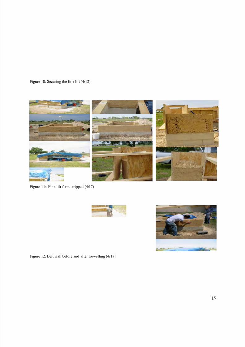
The structure was built in three lifts of 2' height, each. After each lift, the structure was coveredwith tarp to protect against the expected rain (Figure 10). The forms were reused repeatedly forthe three lifts. After stripping the forms, the gaps, through holes and irregularities on the surface
were patched with mud plaster (Figure 11 and Figure 12).
The dampness of the material, the uniformity of compaction and adequate drying of the wallwere important, or the result might be dry, crumbly bands of loose material in the wall, creatingplanes of structural weakness after the forms have been removed. This was observed after anearly removal of formwork of the second lift which was done the day before (Figure 17). Thewall started to bulge where we took the first piece of formwork off. We ended up cutting waypart of the wall where it cracked and re-rammed it after putting the forms back on.
In the entire process, material handling was a major task, and if it is to be done by hand (as inthis project); adequate labor, budget and time requirements must be recognized. It will require
approximately one one-hour of labor to place one cubic yard of material by shovel (McHenry1984).
8/6/2019 Earth Shack Report
http://slidepdf.com/reader/full/earth-shack-report 14/35
14
Concrete base Securing formwork horizontally Securing formwork vertically
Figure 7: Setting up formwork for the first lift (4/10)
Figure 8: Soil brought to the site (4/10)
Preparing the soil mix Earth was filled in 4”-6” layers Handheld rammers for tamping
Figure 9: Erecting the first lift (4/12)
8/6/2019 Earth Shack Report
http://slidepdf.com/reader/full/earth-shack-report 15/35
15
Figure 10: Securing the first lift (4/12)
Figure 11: First lift form stripped (4/17)
Figure 12: Left wall before and after trowelling (4/17)
8/6/2019 Earth Shack Report
http://slidepdf.com/reader/full/earth-shack-report 16/35
16
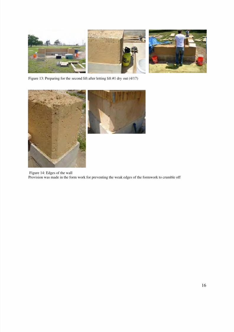
Figure 13: Preparing for the second lift after letting lift #1 dry out (4/17)
Figure 14: Edges of the wallProvision was made in the form work for preventing the weak edges of the formwork to crumble off
8/6/2019 Earth Shack Report
http://slidepdf.com/reader/full/earth-shack-report 17/35
17
8.2. Window openings in the second lift
All openings in the earth walls must be provided with a lintel structure strong enough to span theopening width, with provisions for anchoring door and window jambs to the wall. Generally,doors present more of a problem than window frames because of the vibration. While a solid
cured earth wall seems to accept material fastener such as nails and expansion bolt fastenerssecurely at inception; vibration, time, different expansion coefficients, and the oxidation effectsof material fasteners will ultimately cause a loosening the fasteners in the wall. Solid woodanchors, placed in the wall as it is built, are less likely to cause future problems (McHenry 1984).
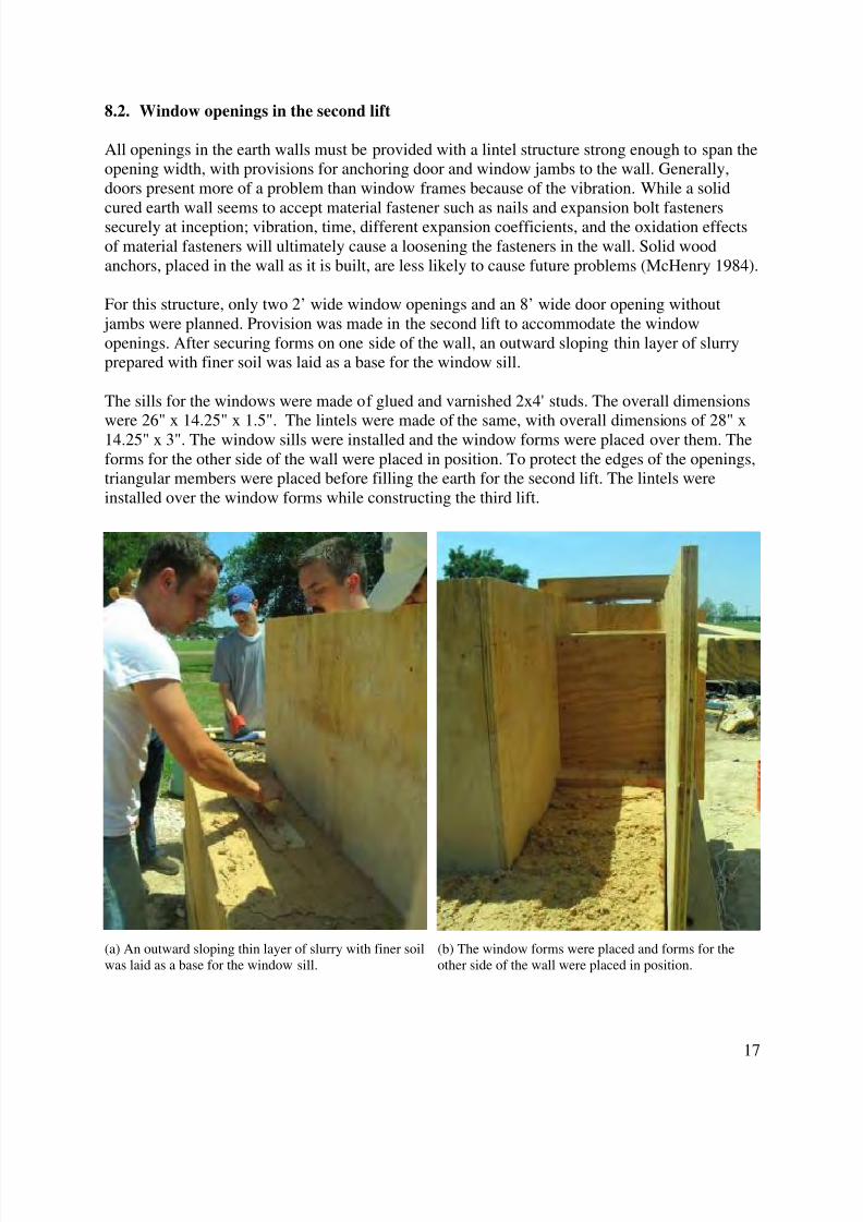
For this structure, only two 2’ wide window openings and an 8’ wide door opening without jambs were planned. Provision was made in the second lift to accommodate the windowopenings. After securing forms on one side of the wall, an outward sloping thin layer of slurryprepared with finer soil was laid as a base for the window sill.
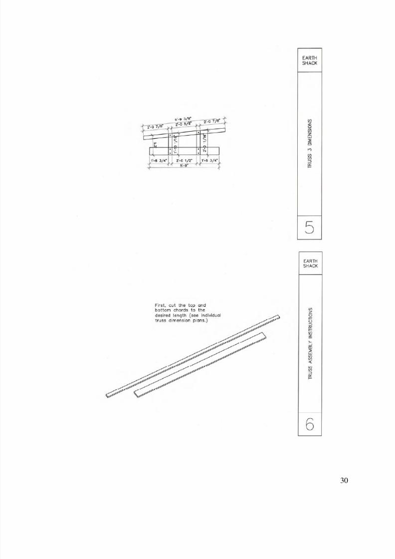
The sills for the windows were made of glued and varnished 2x4' studs. The overall dimensions
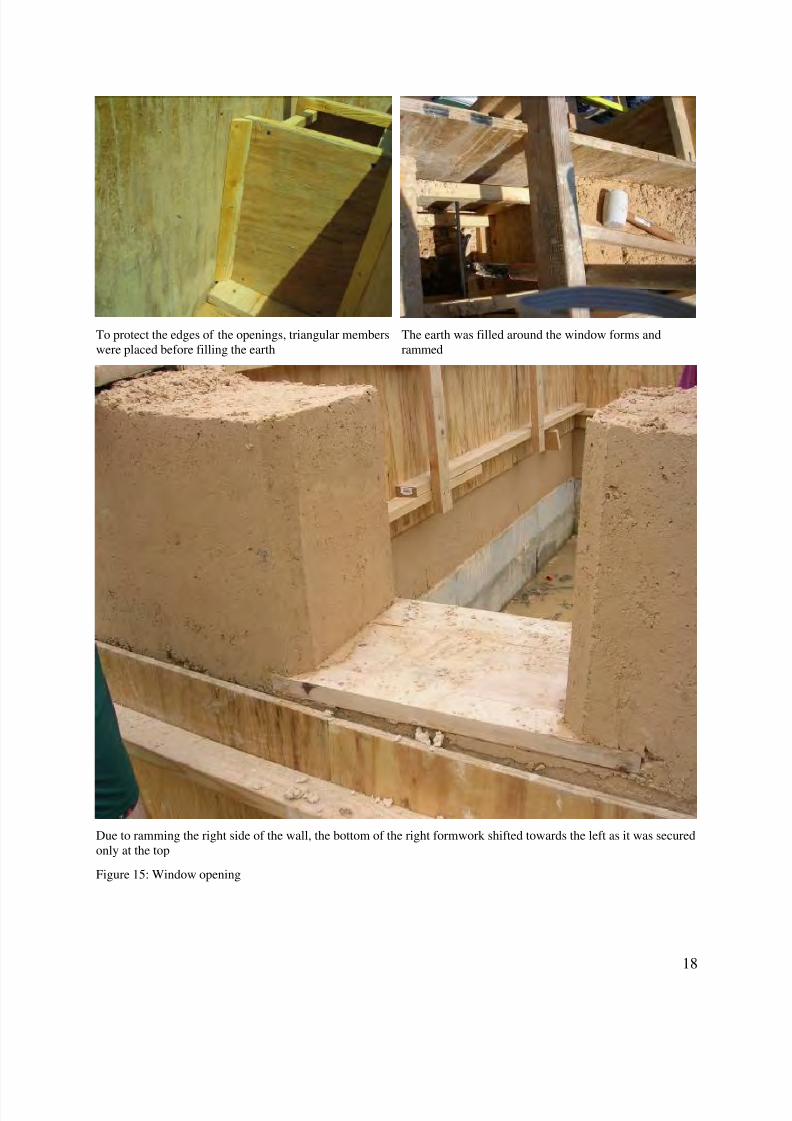
were 26" x 14.25" x 1.5". The lintels were made of the same, with overall dimensions of 28" x14.25" x 3". The window sills were installed and the window forms were placed over them. Theforms for the other side of the wall were placed in position. To protect the edges of the openings,triangular members were placed before filling the earth for the second lift. The lintels wereinstalled over the window forms while constructing the third lift.
(a) An outward sloping thin layer of slurry with finer soilwas laid as a base for the window sill.
(b) The window forms were placed and forms for theother side of the wall were placed in position.
8/6/2019 Earth Shack Report
http://slidepdf.com/reader/full/earth-shack-report 18/35
18
To protect the edges of the openings, triangular memberswere placed before filling the earth
The earth was filled around the window forms andrammed
Due to ramming the right side of the wall, the bottom of the right formwork shifted towards the left as it was securedonly at the top
Figure 15: Window opening
8/6/2019 Earth Shack Report
http://slidepdf.com/reader/full/earth-shack-report 19/35
19
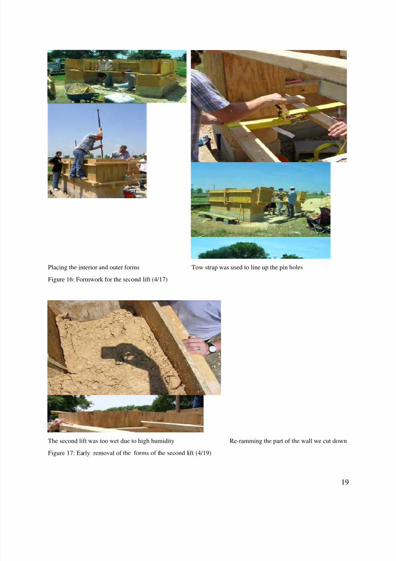
Placing the interior and outer forms Tow strap was used to line up the pin holes
Figure 16: Formwork for the second lift (4/17)
The second lift was too wet due to high humidity Re-ramming the part of the wall we cut down
Figure 17: Early removal of the forms of the second lift (4/19)
8/6/2019 Earth Shack Report
http://slidepdf.com/reader/full/earth-shack-report 20/35
20
8.3. Protection against the weather
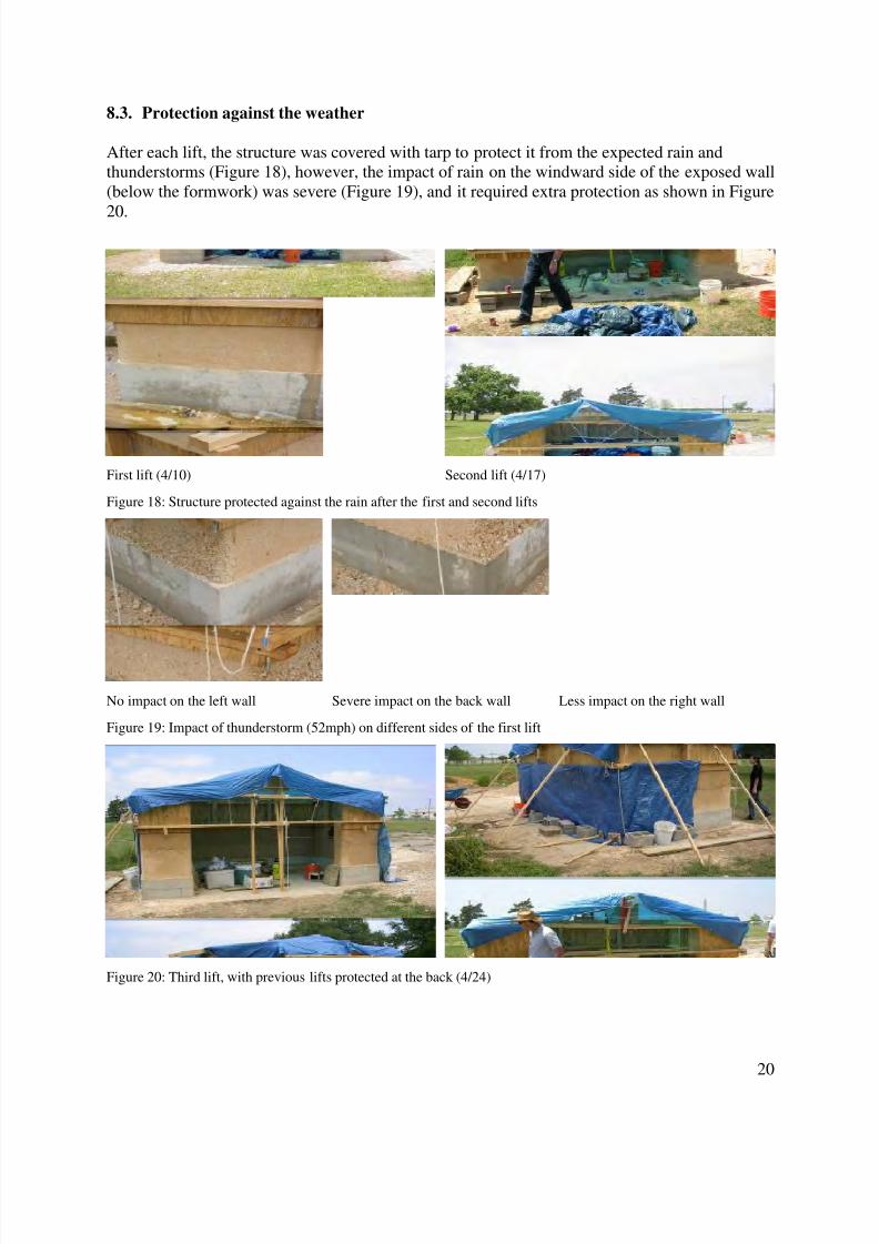
After each lift, the structure was covered with tarp to protect it from the expected rain andthunderstorms (Figure 18), however, the impact of rain on the windward side of the exposed wall(below the formwork) was severe (Figure 19), and it required extra protection as shown in Figure
20.
First lift (4/10) Second lift (4/17)
Figure 18: Structure protected against the rain after the first and second lifts
No impact on the left wall Severe impact on the back wall Less impact on the right wall
Figure 19: Impact of thunderstorm (52mph) on different sides of the first lift
Figure 20: Third lift, with previous lifts protected at the back (4/24)

8/6/2019 Earth Shack Report
http://slidepdf.com/reader/full/earth-shack-report 21/35
21
8.4. Additional reinforcement in third lift
Additional vertical reinforcement was provided in the third lift using 3’ long all-threaded bars.Besides providing lateral strength, these bars acted as elements to secure bond beams against thewall. These bars were placed vertically in the formwork at approximately 2’ on center, with
twisted metal plates on the bottom for good anchoring. Studs spanning over the entire width of the wall, were used as cross supports to secure these bars vertically while compacting the eartharound them. As a safety measure, the exposed ends of these bars were covered with empty cansof coke (Figure 21).
Figure 21: Additional reinforcementThreaded bars used for vertical reinforcement; cross supports securing the vertical bars in place; coke cans covering
the exposed bars
8/6/2019 Earth Shack Report
http://slidepdf.com/reader/full/earth-shack-report 22/35
22
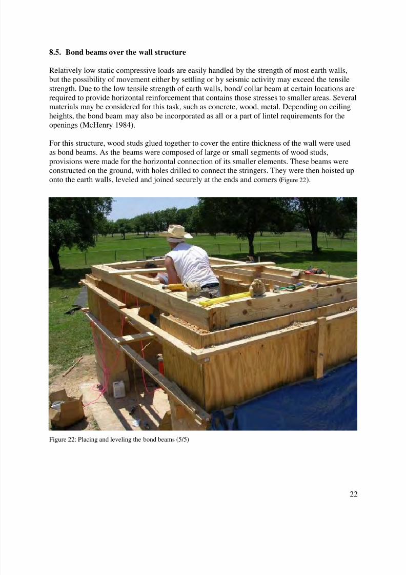
8.5. Bond beams over the wall structure
Relatively low static compressive loads are easily handled by the strength of most earth walls,but the possibility of movement either by settling or by seismic activity may exceed the tensilestrength. Due to the low tensile strength of earth walls, bond/ collar beam at certain locations are
required to provide horizontal reinforcement that contains those stresses to smaller areas. Severalmaterials may be considered for this task, such as concrete, wood, metal. Depending on ceilingheights, the bond beam may also be incorporated as all or a part of lintel requirements for theopenings (McHenry 1984).
For this structure, wood studs glued together to cover the entire thickness of the wall were usedas bond beams. As the beams were composed of large or small segments of wood studs,provisions were made for the horizontal connection of its smaller elements. These beams wereconstructed on the ground, with holes drilled to connect the stringers. They were then hoisted uponto the earth walls, leveled and joined securely at the ends and corners (Figure 22).
Figure 22: Placing and leveling the bond beams (5/5)
8/6/2019 Earth Shack Report
http://slidepdf.com/reader/full/earth-shack-report 23/35
23
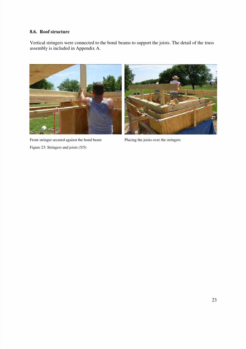
8.6. Roof structure
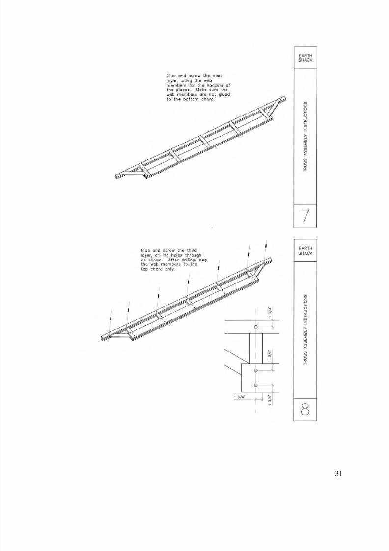
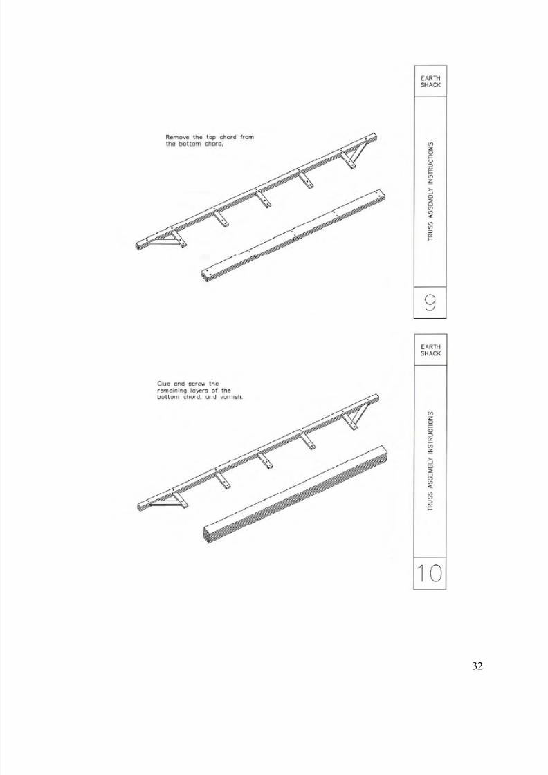
Vertical stringers were connected to the bond beams to support the joists. The detail of the trussassembly is included in Appendix A.
Front stringer secured against the bond beam Placing the joists over the stringers
Figure 23: Stringers and joists (5/5)
8/6/2019 Earth Shack Report
http://slidepdf.com/reader/full/earth-shack-report 24/35
24
9. Lessons learned
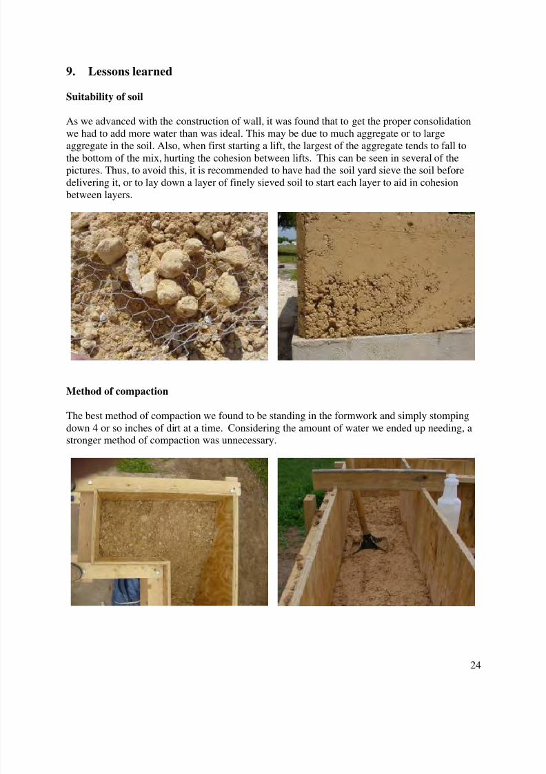
Suitability of soil
As we advanced with the construction of wall, it was found that to get the proper consolidation
we had to add more water than was ideal. This may be due to much aggregate or to largeaggregate in the soil. Also, when first starting a lift, the largest of the aggregate tends to fall tothe bottom of the mix, hurting the cohesion between lifts. This can be seen in several of thepictures. Thus, to avoid this, it is recommended to have had the soil yard sieve the soil beforedelivering it, or to lay down a layer of finely sieved soil to start each layer to aid in cohesionbetween layers.
Method of compaction
The best method of compaction we found to be standing in the formwork and simply stompingdown 4 or so inches of dirt at a time. Considering the amount of water we ended up needing, astronger method of compaction was unnecessary.
8/6/2019 Earth Shack Report
http://slidepdf.com/reader/full/earth-shack-report 25/35
25
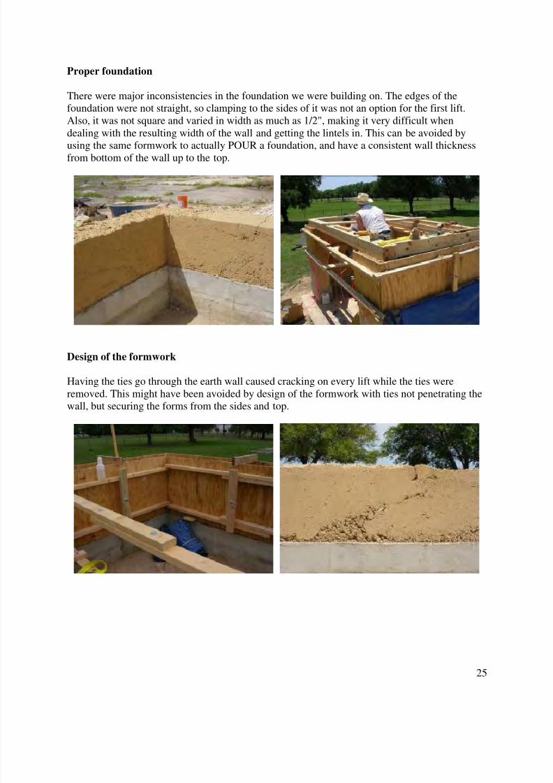
Proper foundation
There were major inconsistencies in the foundation we were building on. The edges of thefoundation were not straight, so clamping to the sides of it was not an option for the first lift.Also, it was not square and varied in width as much as 1/2", making it very difficult when
dealing with the resulting width of the wall and getting the lintels in. This can be avoided byusing the same formwork to actually POUR a foundation, and have a consistent wall thicknessfrom bottom of the wall up to the top.
Design of the formwork
Having the ties go through the earth wall caused cracking on every lift while the ties wereremoved. This might have been avoided by design of the formwork with ties not penetrating the
wall, but securing the forms from the sides and top.
8/6/2019 Earth Shack Report
http://slidepdf.com/reader/full/earth-shack-report 26/35
26
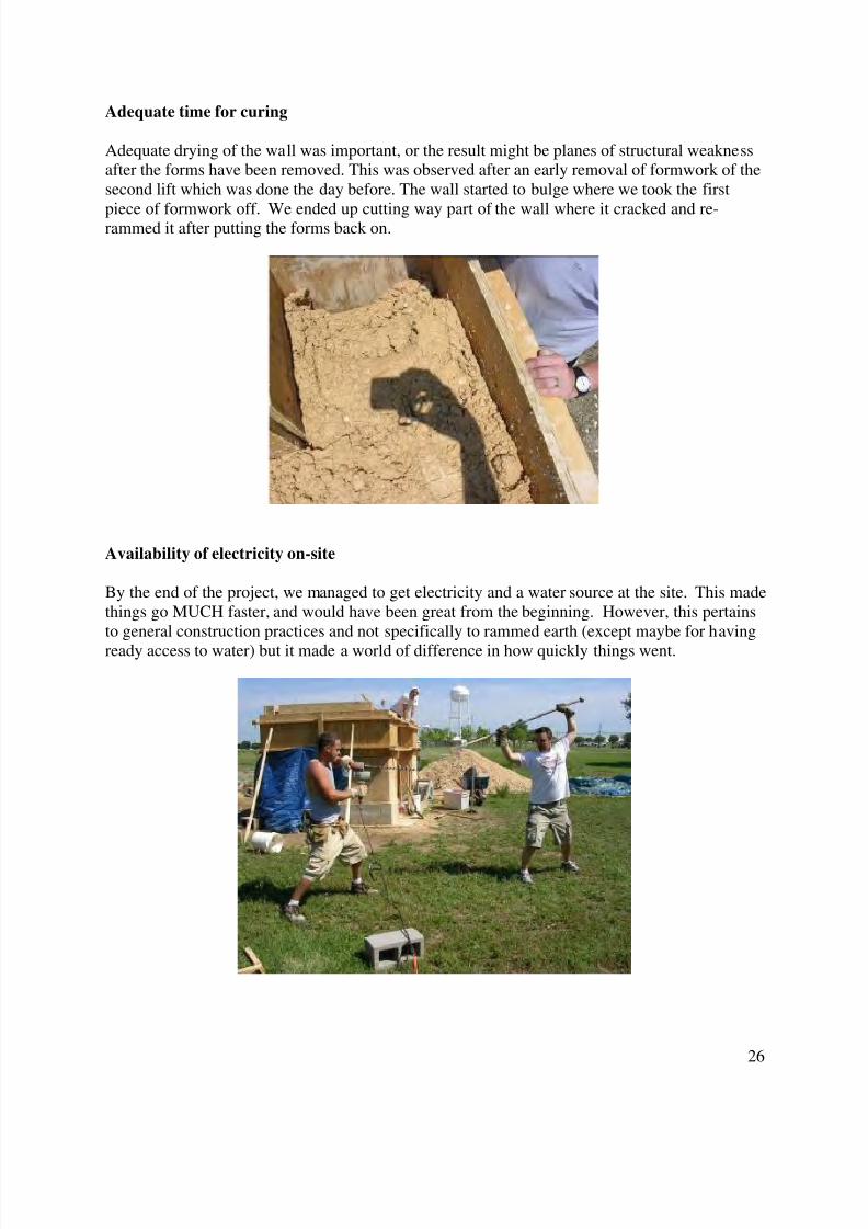
Adequate time for curing
Adequate drying of the wall was important, or the result might be planes of structural weaknessafter the forms have been removed. This was observed after an early removal of formwork of thesecond lift which was done the day before. The wall started to bulge where we took the first
piece of formwork off. We ended up cutting way part of the wall where it cracked and re-rammed it after putting the forms back on.
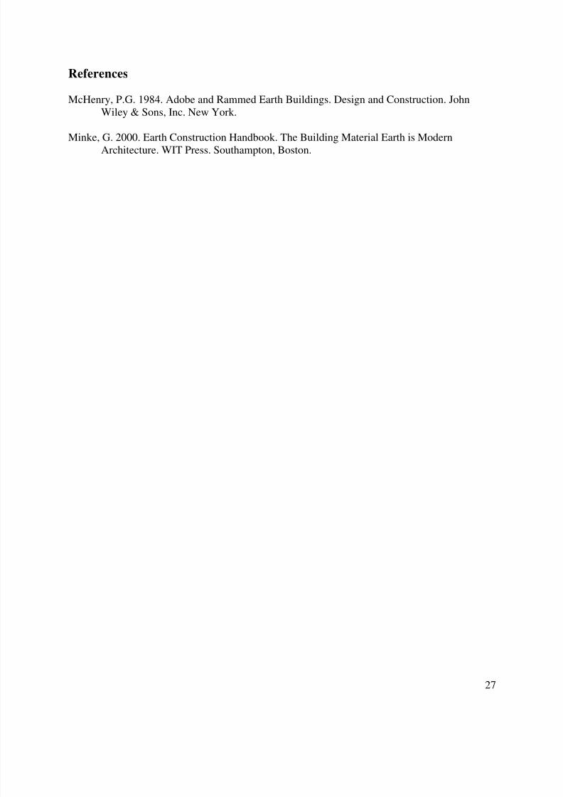
Availability of electricity on-site
By the end of the project, we managed to get electricity and a water source at the site. This madethings go MUCH faster, and would have been great from the beginning. However, this pertainsto general construction practices and not specifically to rammed earth (except maybe for having
ready access to water) but it made a world of difference in how quickly things went.
8/6/2019 Earth Shack Report
http://slidepdf.com/reader/full/earth-shack-report 27/35
27
References
McHenry, P.G. 1984. Adobe and Rammed Earth Buildings. Design and Construction. JohnWiley & Sons, Inc. New York.
Minke, G. 2000. Earth Construction Handbook. The Building Material Earth is ModernArchitecture. WIT Press. Southampton, Boston.
8/6/2019 Earth Shack Report
http://slidepdf.com/reader/full/earth-shack-report 28/35
28
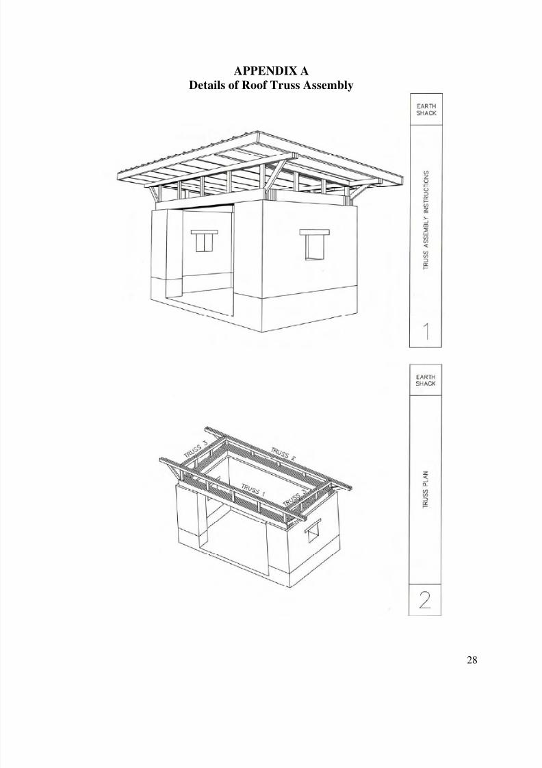
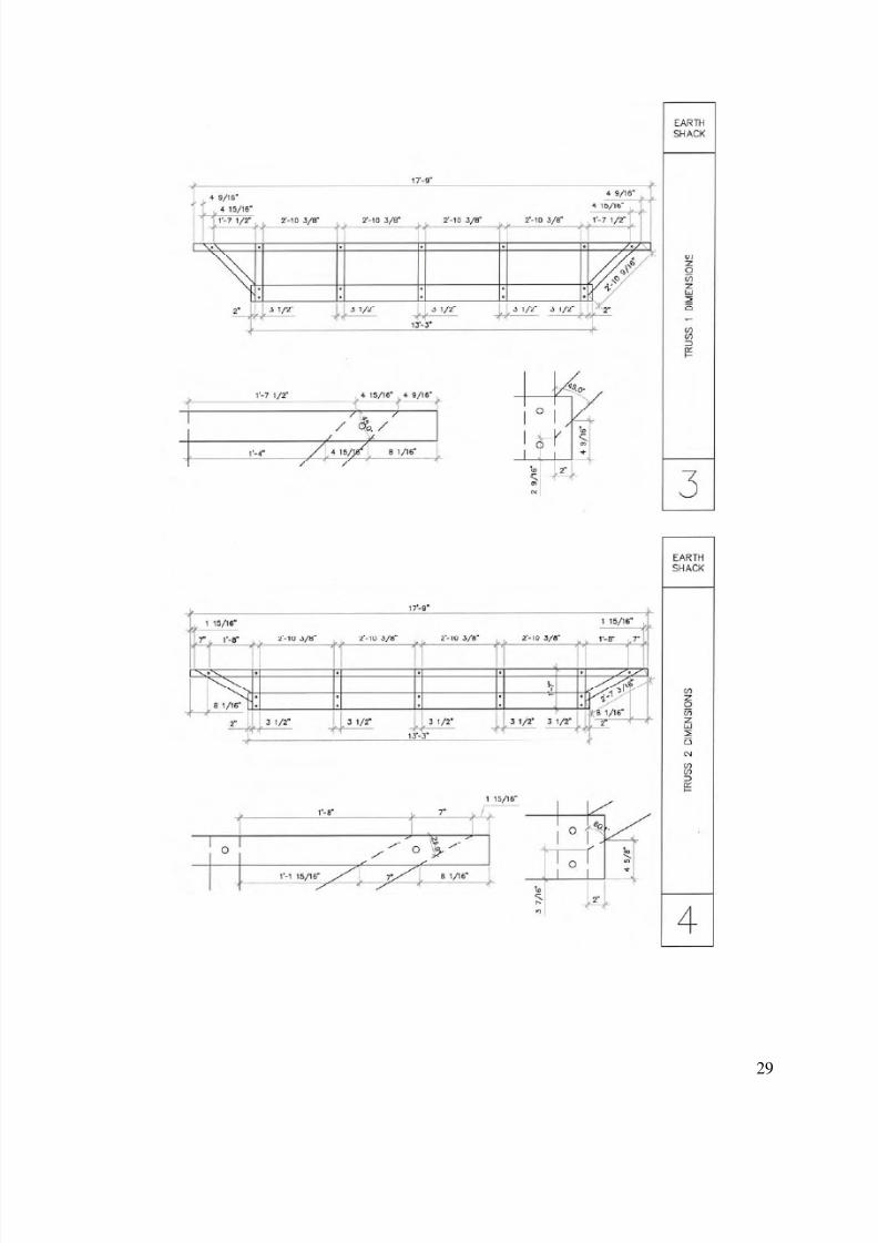
APPENDIX A
Details of Roof Truss Assembly
8/6/2019 Earth Shack Report
http://slidepdf.com/reader/full/earth-shack-report 29/35
29
8/6/2019 Earth Shack Report
http://slidepdf.com/reader/full/earth-shack-report 30/35
30
8/6/2019 Earth Shack Report
http://slidepdf.com/reader/full/earth-shack-report 31/35
31
8/6/2019 Earth Shack Report
http://slidepdf.com/reader/full/earth-shack-report 32/35
32

8/6/2019 Earth Shack Report
http://slidepdf.com/reader/full/earth-shack-report 33/35
33
APPENDIX B
Details of Exterior Finish
8/6/2019 Earth Shack Report
http://slidepdf.com/reader/full/earth-shack-report 34/35
34
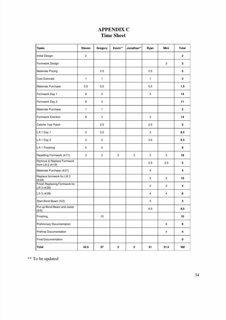
APPENDIX C
Time Sheet
Tasks Steven Gregory Kevin** Jonathan** Ryan Mini Total
Initial Design 2 2
Formwork Design 3 3
Materials Pricing 2.5 2.5 5
Cost Estimate 1 1 1 3
Materials Purchase 0.5 0.5 0.5 1.5
Formwork Day 1 8 3 3 14
Formwork Day 2 8 3 11
Materials Purchase 1 1 2
Formwork Erection 8 3 3 14
Caliche Test Patch 2.5 2.5 5
Lift 1 Day 1 3 2.5 3 8.5
Lift 1 Day 2 4 2 3.5 9.5
Lift 1 Finishing 5 3 8
Resetting Formwork (4/17) 3 3 3 3 3 3 18
Remove & Replace Formwork
from Lift 2 (4/19)2.5 2.5 5
Materials Purchase (4/21) 4 4
Replace formwork for Lift 3
(4/24)5 5 10
Finish Replacing Formwork for
Lift 3 (4/26)2 2 4
Lift 3 (4/28) 4 4 8
Start Bond Beam (5/2) 3 3
Put up Bond Beam and Joists
(5/5)8.5 8.5
Finishing 10 10
Preliminary Documentation 8 8
Prefinal Documentation 4 4
Final Documentation 0
Total 43.5 37 3 3 51 31.5 169
** To be updated
8/6/2019 Earth Shack Report
http://slidepdf.com/reader/full/earth-shack-report 35/35
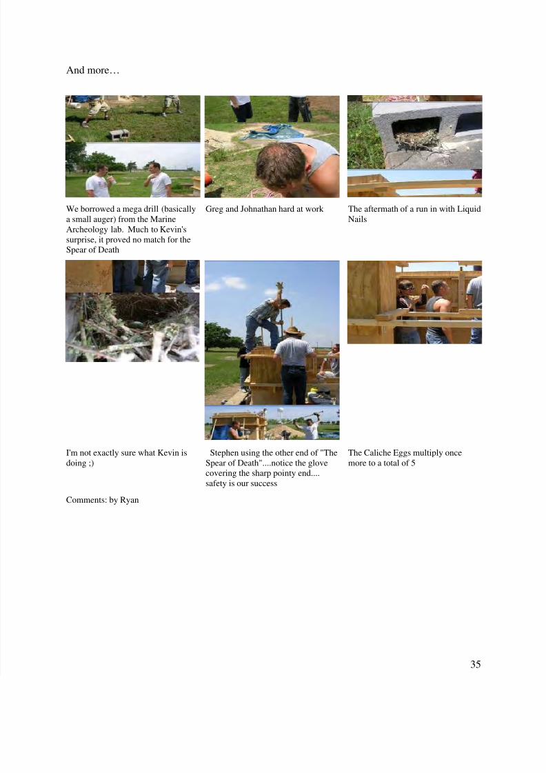
And more…
We borrowed a mega drill (basicallya small auger) from the MarineArcheology lab. Much to Kevin'ssurprise, it proved no match for theSpear of Death
Greg and Johnathan hard at work The aftermath of a run in with LiquidNails
I'm not exactly sure what Kevin isdoing ;)
Stephen using the other end of "TheSpear of Death"....notice the glovecovering the sharp pointy end....safety is our success
The Caliche Eggs multiply oncemore to a total of 5
Comments: by Ryan