DYNAMIC STEERING FOR IMPROVED SENSOR AUTONOMY AND …
11
DYNAMIC STEERING FOR IMPROVED SENSOR AUTONOMY AND CATALOGUE MAINTENANCE Tyler A. Hobson* and I. Vaughan L. Clarkson School of Information Technology and Electrical Engineering, The University of Queensland, Australia Travis Bessell, Mark Rutten and Neil Gordon National Security and Intelligence Division, Defence Science and Technology Group, Australia ABSTRACT A number of international agencies endeavour to maintain catalogues of the man-made resident space objects (RSOs) currently orbiting the Earth. Such catalogues are primarily created to anticipate and avoid destructive collisions involving important space assets such as manned missions and active satellites. An agency’s ability to achieve this objective is dependent on the accuracy, reliability and timeliness of the information used to update its catalogue. A primary means for gathering this information is by regularly making direct observations of the tens-of-thousands of currently detectable RSOs via networks of space surveillance sensors. But operational constraints sometimes prevent accurate and timely reacquisition of all known RSOs, which can cause them to become lost to the tracking system. Furthermore, when comprehensive acquisition of new objects does not occur, these objects, in addition to the lost RSOs, result in uncorrelated detections when next observed. Due to the rising number of space-missions and the introduction of newer, more capable space-sensors, the number of uncorrelated targets is at an all-time high. The process of differentiating uncorrelated detections caused by once-acquired now-lost RSOs from newly detected RSOs is a difficult and often labour intensive task. Current methods for overcoming this challenge focus on advancements in orbit propagation and object characterisation to improve prediction accuracy and target identification. In this paper, we describe a complementary approach that incorporates increased awareness of error and failed observations into the RSO tracking solution. Our methodology employs a technique called dynamic steering to improve the autonomy and capability of a space surveillance network’s steerable sensors. By co-situating each sensor with a low-cost high-performance computer, the steerable sensor can quickly and intelligently determine where to steer in order to improve its utility. The sensor-system uses a dedicated parallel-processing architecture to enable it to compute a high-fidelity estimate of the target’s prior state error distribution in real-time. Negative information, such as when an RSO is targeted for observation but it is not observed, is incorporated to improve the likelihood of reacquiring the target when attempting to observe the target in future. The sensor is consequently capable of improving its utility by planning each observation using a sensor steering solution that is informed by all prior attempts at observing the target. We describe the practical implementation of a single experimental sensor and offer the results of recent field measurements and simulations. The proposed approach is applied to the task of Initial Orbit Determination (IOD). By first developing and incorporating a constrained admissible region (CAR), the system is capable of reacquiring an RSO months after it was briefly observed and in spite of the apparent lack of tracking information. The system consequently offers a means of enhancing surveillance for Space Situational Awareness (SSA) via increased system capacity, a higher degree of autonomy and the ability to reacquire objects whose dynamics are insufficiently modelled to cue a conventional space surveillance system for observation and tracking. 1. INTRODUCTION Destructive collisions of objects in orbit about the Earth threaten the economic viability of space-faring, national security and safety-of-flight of manned space missions [1]. In order to prevent collisions in orbit, a number of international agencies maintain catalogues of as many man-made resident space objects (RSOs) as possible. Such catalogues are used to improve Space Situational Awareness (SAA) permitting the holistic prediction and planning necessary to prevent collisions. The utility and reliability of these catalogues is dependent on the accuracy and timeliness of the information used to maintain them [1]. A crucial source of this information is the regular and direct observation of the tens-of-thousands of RSOs that are currently detectable to these agency’s networks of space surveillance sensors. But operational constraints to sensor availability, dynamical modelling and tracking methodologies, can occasionally prevent accurate and timely orbit determination of new detections and reacquisition of catalogued RSOs. Consequently, in spite of an agency’s best efforts, RSOs can become lost to the tracking
Transcript of DYNAMIC STEERING FOR IMPROVED SENSOR AUTONOMY AND …
DYNAMIC STEERING FOR IMPROVED SENSOR AUTONOMY ANDCATALOGUE MAINTENANCE
Tyler A. Hobson* and I. Vaughan L. ClarksonSchool of Information Technology and Electrical Engineering,
The University of Queensland, Australia
Travis Bessell, Mark Rutten and Neil GordonNational Security and Intelligence Division,
Defence Science and Technology Group, Australia
ABSTRACT
A number of international agencies endeavour to maintain catalogues of the man-made resident space objects (RSOs)currently orbiting the Earth. Such catalogues are primarily created to anticipate and avoid destructive collisionsinvolving important space assets such as manned missions and active satellites. An agency’s ability to achieve thisobjective is dependent on the accuracy, reliability and timeliness of the information used to update its catalogue.
A primary means for gathering this information is by regularly making direct observations of the tens-of-thousandsof currently detectable RSOs via networks of space surveillance sensors. But operational constraints sometimesprevent accurate and timely reacquisition of all known RSOs, which can cause them to become lost to the trackingsystem. Furthermore, when comprehensive acquisition of new objects does not occur, these objects, in addition tothe lost RSOs, result in uncorrelated detections when next observed. Due to the rising number of space-missions andthe introduction of newer, more capable space-sensors, the number of uncorrelated targets is at an all-time high. Theprocess of differentiating uncorrelated detections caused by once-acquired now-lost RSOs from newly detected RSOsis a difficult and often labour intensive task. Current methods for overcoming this challenge focus on advancementsin orbit propagation and object characterisation to improve prediction accuracy and target identification.
In this paper, we describe a complementary approach that incorporates increased awareness of error and failedobservations into the RSO tracking solution. Our methodology employs a technique called dynamic steering toimprove the autonomy and capability of a space surveillance network’s steerable sensors. By co-situating each sensorwith a low-cost high-performance computer, the steerable sensor can quickly and intelligently determine where tosteer in order to improve its utility. The sensor-system uses a dedicated parallel-processing architecture to enable itto compute a high-fidelity estimate of the target’s prior state error distribution in real-time. Negative information,such as when an RSO is targeted for observation but it is not observed, is incorporated to improve the likelihoodof reacquiring the target when attempting to observe the target in future. The sensor is consequently capable ofimproving its utility by planning each observation using a sensor steering solution that is informed by all priorattempts at observing the target.
We describe the practical implementation of a single experimental sensor and offer the results of recent fieldmeasurements and simulations. The proposed approach is applied to the task of Initial Orbit Determination (IOD).By first developing and incorporating a constrained admissible region (CAR), the system is capable of reacquiringan RSO months after it was briefly observed and in spite of the apparent lack of tracking information. The systemconsequently offers a means of enhancing surveillance for Space Situational Awareness (SSA) via increased systemcapacity, a higher degree of autonomy and the ability to reacquire objects whose dynamics are insufficiently modelledto cue a conventional space surveillance system for observation and tracking.
1. INTRODUCTION
Destructive collisions of objects in orbit about the Earth threaten the economic viability of space-faring, nationalsecurity and safety-of-flight of manned space missions [1]. In order to prevent collisions in orbit, a number ofinternational agencies maintain catalogues of as many man-made resident space objects (RSOs) as possible. Suchcatalogues are used to improve Space Situational Awareness (SAA) permitting the holistic prediction and planningnecessary to prevent collisions. The utility and reliability of these catalogues is dependent on the accuracy andtimeliness of the information used to maintain them [1]. A crucial source of this information is the regular anddirect observation of the tens-of-thousands of RSOs that are currently detectable to these agency’s networks ofspace surveillance sensors. But operational constraints to sensor availability, dynamical modelling and trackingmethodologies, can occasionally prevent accurate and timely orbit determination of new detections and reacquisitionof catalogued RSOs. Consequently, in spite of an agency’s best efforts, RSOs can become lost to the tracking
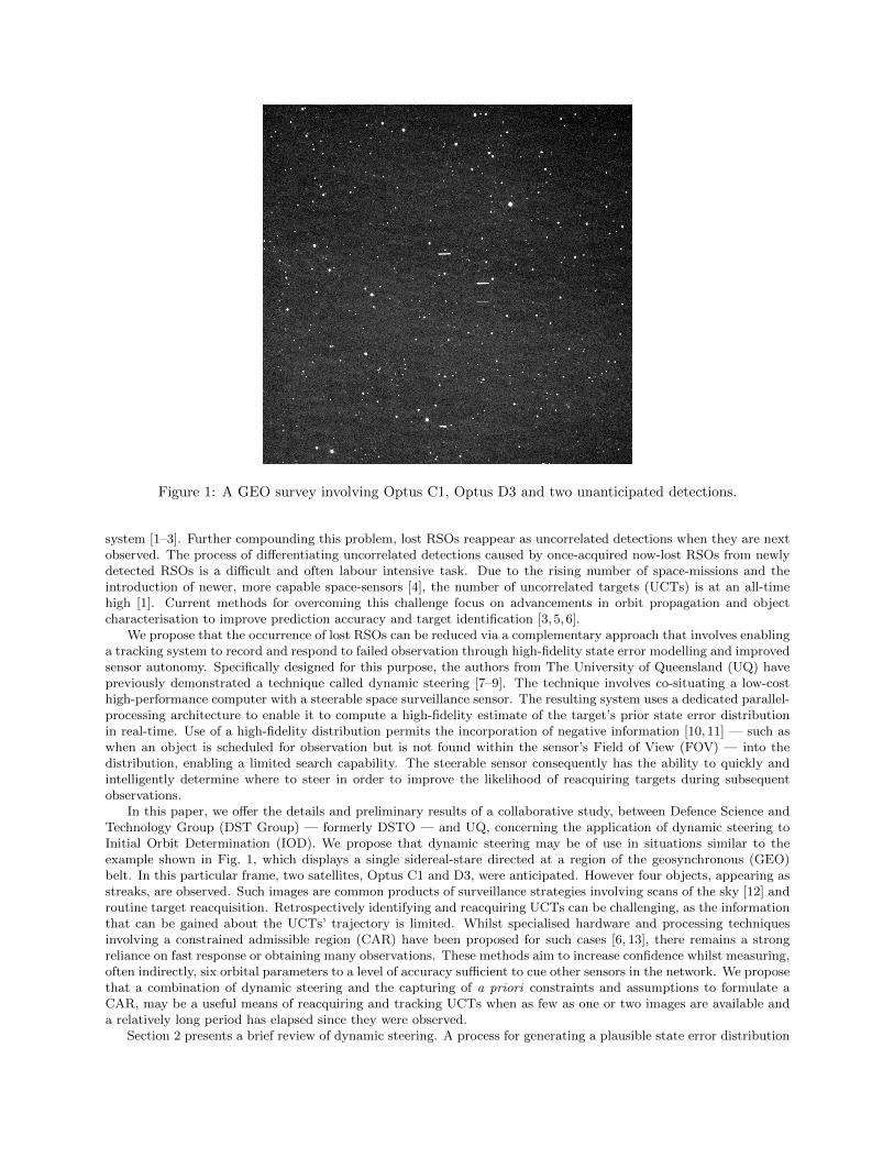
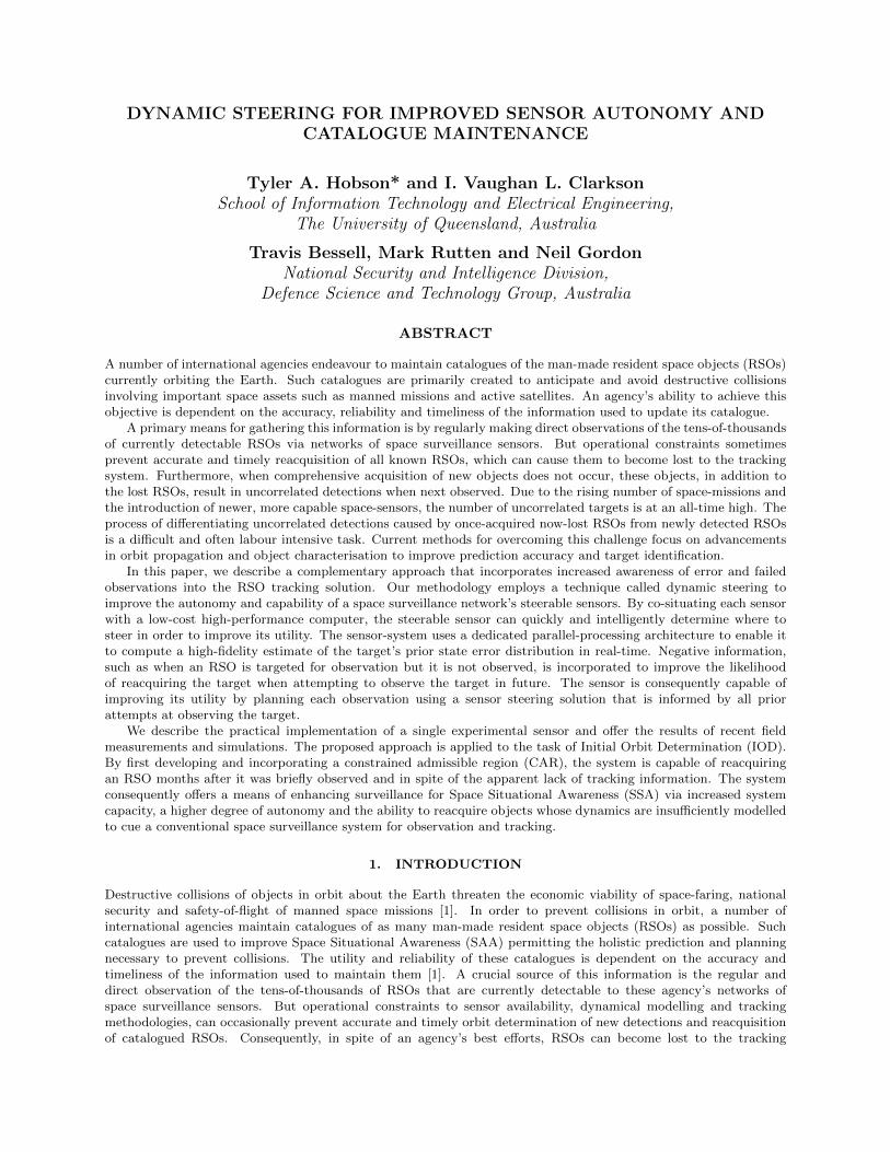
Figure 1: A GEO survey involving Optus C1, Optus D3 and two unanticipated detections.
system [1–3]. Further compounding this problem, lost RSOs reappear as uncorrelated detections when they are nextobserved. The process of differentiating uncorrelated detections caused by once-acquired now-lost RSOs from newlydetected RSOs is a difficult and often labour intensive task. Due to the rising number of space-missions and theintroduction of newer, more capable space-sensors [4], the number of uncorrelated targets (UCTs) is at an all-timehigh [1]. Current methods for overcoming this challenge focus on advancements in orbit propagation and objectcharacterisation to improve prediction accuracy and target identification [3, 5, 6].
We propose that the occurrence of lost RSOs can be reduced via a complementary approach that involves enablinga tracking system to record and respond to failed observation through high-fidelity state error modelling and improvedsensor autonomy. Specifically designed for this purpose, the authors from The University of Queensland (UQ) havepreviously demonstrated a technique called dynamic steering [7–9]. The technique involves co-situating a low-costhigh-performance computer with a steerable space surveillance sensor. The resulting system uses a dedicated parallel-processing architecture to enable it to compute a high-fidelity estimate of the target’s prior state error distributionin real-time. Use of a high-fidelity distribution permits the incorporation of negative information [10, 11] — such aswhen an object is scheduled for observation but is not found within the sensor’s Field of View (FOV) — into thedistribution, enabling a limited search capability. The steerable sensor consequently has the ability to quickly andintelligently determine where to steer in order to improve the likelihood of reacquiring targets during subsequentobservations.
In this paper, we offer the details and preliminary results of a collaborative study, between Defence Science andTechnology Group (DST Group) — formerly DSTO — and UQ, concerning the application of dynamic steering toInitial Orbit Determination (IOD). We propose that dynamic steering may be of use in situations similar to theexample shown in Fig. 1, which displays a single sidereal-stare directed at a region of the geosynchronous (GEO)belt. In this particular frame, two satellites, Optus C1 and D3, were anticipated. However four objects, appearing asstreaks, are observed. Such images are common products of surveillance strategies involving scans of the sky [12] androutine target reacquisition. Retrospectively identifying and reacquiring UCTs can be challenging, as the informationthat can be gained about the UCTs’ trajectory is limited. Whilst specialised hardware and processing techniquesinvolving a constrained admissible region (CAR) have been proposed for such cases [6, 13], there remains a strongreliance on fast response or obtaining many observations. These methods aim to increase confidence whilst measuring,often indirectly, six orbital parameters to a level of accuracy sufficient to cue other sensors in the network. We proposethat a combination of dynamic steering and the capturing of a priori constraints and assumptions to formulate aCAR, may be a useful means of reacquiring and tracking UCTs when as few as one or two images are available anda relatively long period has elapsed since they were observed.
Section 2 presents a brief review of dynamic steering. A process for generating a plausible state error distribution
via a CAR is proposed in Section 3. Details regarding the experimental system currently employed by DST Groupand UQ is detailed in Section 4. Section 5 presents some preliminary data regarding recent field measurements andsimulated trials. A concluding discussion is presented in Section 6.
2. REVIEW OF DYNAMIC STEERING
The technique known as dynamic steering has recently been presented and demonstrated by the authors from UQ [7–9].Dynamic steering was devised as a means of improving the utility of a space surveillance network’s steerable sensors,particularly those featuring a relatively constrained FOV. Their utility is improved by enabling these sensors to trackand, when required, record and exploit negative information to improve the likelihood of finding a target in futureobservations.
Dynamic steering is implemented via an augmented Bayesian filtering process. As shown in Fig. 2, a sensor-steering and observation evaluation step are inserted in between a conventional Bayesian filter’s time update, ob-servation and measurement update steps. Incorporating these additional elements achieves a feedback loop thatcombines sensor control and tracking into a single solution, capable of reacting to the outcome of an observation inreal time.
Time Update
Sensor Steering
Observation
Measurement Evaluation
Measurement Update
k :=k + 1
Figure 2: The Bayesian sequential update process with additional (red) steps for dynamic steering.
2.1 Sensor Steering
The role of the sensor steering step is to determine where to point the sensor based on the prior distribution producedduring the preceding Bayesian time update. If xk is the state of the target at time k and z1:k−1 is the set of allattempted observations of the target up until time k, the prior is described by the probability density p(xk|z1:k−1).
There are a number of alternative strategies that may be devised to steer the sensor. The question of how tooptimally steer the sensor according to the prior remains unresolved. However employing a greedy maximum weightsteering strategy, of aiming the sensor in the direction that gains the maximum probability of detection, has thus fardemonstrated the greatest potential in the most test cases [9].
To describe the maximum weight sensor steering process, we begin by defining the sensor aiming vector Ψ.This vector contains at least the sensor pointing angles, such as right-ascension α and declination δ, but may alsoinclude sensor-specific characteristics such as cost metrics for sensor slewing, unobservable elevations and gimbal-locklimits. An objective function J(Ψ) may be used to evaluate the aiming parameters that achieve the maximum utility,by locating the global maxima. Presuming the sensor’s FOV is known but undisclosed, an objective function forobtaining pointing angles with the greatest probability of detection may be described by the equation
J(Ψ) =
∫χ
I(FOV(Ψ))p(xk | zk−1) dx, (1)
where I is an indicator function defined by
I(FOV(Ψ)) =
{1 x ∈ FOV(Ψ)0 otherwise
, (2)
χ is the state space and FOV(Ψ) is the volume, within state space, that is directly or indirectly observable by thesensor’s FOV when steered according to Ψ.
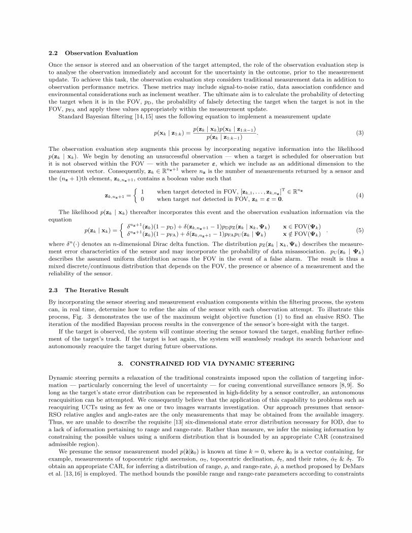
2.2 Observation Evaluation
Once the sensor is steered and an observation of the target attempted, the role of the observation evaluation step isto analyse the observation immediately and account for the uncertainty in the outcome, prior to the measurementupdate. To achieve this task, the observation evaluation step considers traditional measurement data in addition toobservation performance metrics. These metrics may include signal-to-noise ratio, data association confidence andenvironmental considerations such as inclement weather. The ultimate aim is to calculate the probability of detectingthe target when it is in the FOV, pD, the probability of falsely detecting the target when the target is not in theFOV, pFA and apply these values appropriately within the measurement update.
Standard Bayesian filtering [14,15] uses the following equation to implement a measurement update
p(xk | z1:k) =p(zk | xk)p(xk | z1:k−1)
p(zk | z1:k−1). (3)
The observation evaluation step augments this process by incorporating negative information into the likelihoodp(zk | xk). We begin by denoting an unsuccessful observation — when a target is scheduled for observation butit is not observed within the FOV — with the parameter ε, which we include as an additional dimension to themeasurement vector. Consequently, zk ∈ Rnz+1 where nz is the number of measurements returned by a sensor andthe (nz + 1)th element, zk,nz+1, contains a boolean value such that
zk,nz+1 =
{1 when target detected in FOV, [zk,1, . . . , zk,nz ]T ∈ Rnz
0 when target not detected in FOV, zk = ε = 0.(4)
The likelihood p(zk | xk) thereafter incorporates this event and the observation evaluation information via theequation
p(zk | xk) =
{δnz+1(zk)(1− pD) + δ(zk,nz+1 − 1)pDpZ(zk | xk,Ψk) x ∈ FOV(Ψk)δnz+1(zk)(1− pFA) + δ(zk,nz+1 − 1)pFApU(zk | Ψk) x /∈ FOV(Ψk)
. (5)
where δn(·) denotes an n-dimensional Dirac delta function. The distribution pZ(zk | xk,Ψk) describes the measure-ment error characteristics of the sensor and may incorporate the probability of data misassociation. pU(zk | Ψk)describes the assumed uniform distribution across the FOV in the event of a false alarm. The result is thus amixed discrete/continuous distribution that depends on the FOV, the presence or absence of a measurement and thereliability of the sensor.
2.3 The Iterative Result
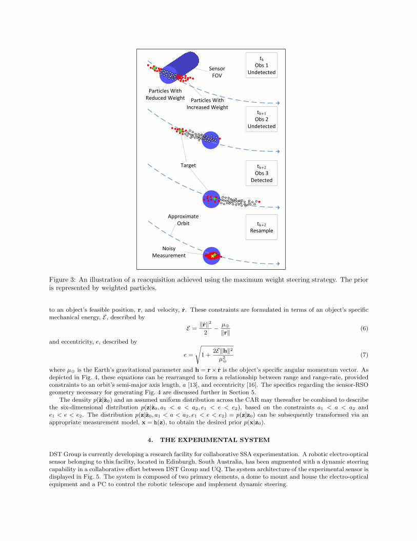
By incorporating the sensor steering and measurement evaluation components within the filtering process, the systemcan, in real time, determine how to refine the aim of the sensor with each observation attempt. To illustrate thisprocess, Fig. 3 demonstrates the use of the maximum weight objective function (1) to find an elusive RSO. Theiteration of the modified Bayesian process results in the convergence of the sensor’s bore-sight with the target.
If the target is observed, the system will continue steering the sensor toward the target, enabling further refine-ment of the target’s track. If the target is lost again, the system will seamlessly readopt its search behaviour andautonomously reacquire the target during future observations.
3. CONSTRAINED IOD VIA DYNAMIC STEERING
Dynamic steering permits a relaxation of the traditional constraints imposed upon the collation of targeting infor-mation — particularly concerning the level of uncertainty — for cueing conventional surveillance sensors [8, 9]. Solong as the target’s state error distribution can be represented in high-fidelity by a sensor controller, an autonomousreacquisition can be attempted. We consequently believe that the application of this capability to problems such asreacquiring UCTs using as few as one or two images warrants investigation. Our approach presumes that sensor-RSO relative angles and angle-rates are the only measurements that may be obtained from the available imagery.Thus, we are unable to describe the requisite [13] six-dimensional state error distribution necessary for IOD, due toa lack of information pertaining to range and range-rate. Rather than measure, we infer the missing information byconstraining the possible values using a uniform distribution that is bounded by an appropriate CAR (constrainedadmissible region).
We presume the sensor measurement model p(z|z0) is known at time k = 0, where z0 is a vector containing, forexample, measurements of topocentric right ascension, αT, topocentric declination, δT, and their rates, αT & δT. Toobtain an appropriate CAR, for inferring a distribution of range, ρ, and range-rate, ρ, a method proposed by DeMarset al. [13,16] is employed. The method bounds the possible range and range-rate parameters according to constraints
tkObs 1
Undetected
tk+1Obs 2
Undetected
tk+2Obs 3
Detected
tk+2Resample
Target
Sensor FOV
Particles With Reduced Weight Particles With
Increased Weight
Approximate Orbit
Noisy Measurement
Figure 3: An illustration of a reacquisition achieved using the maximum weight steering strategy. The prioris represented by weighted particles.
to an object’s feasible position, r, and velocity, r. These constraints are formulated in terms of an object’s specificmechanical energy, E , described by
E =‖r‖2
2− µ⊕
‖r‖ (6)
and eccentricity, e, described by
e =
√1 +
2E‖h‖2µ2⊕
(7)
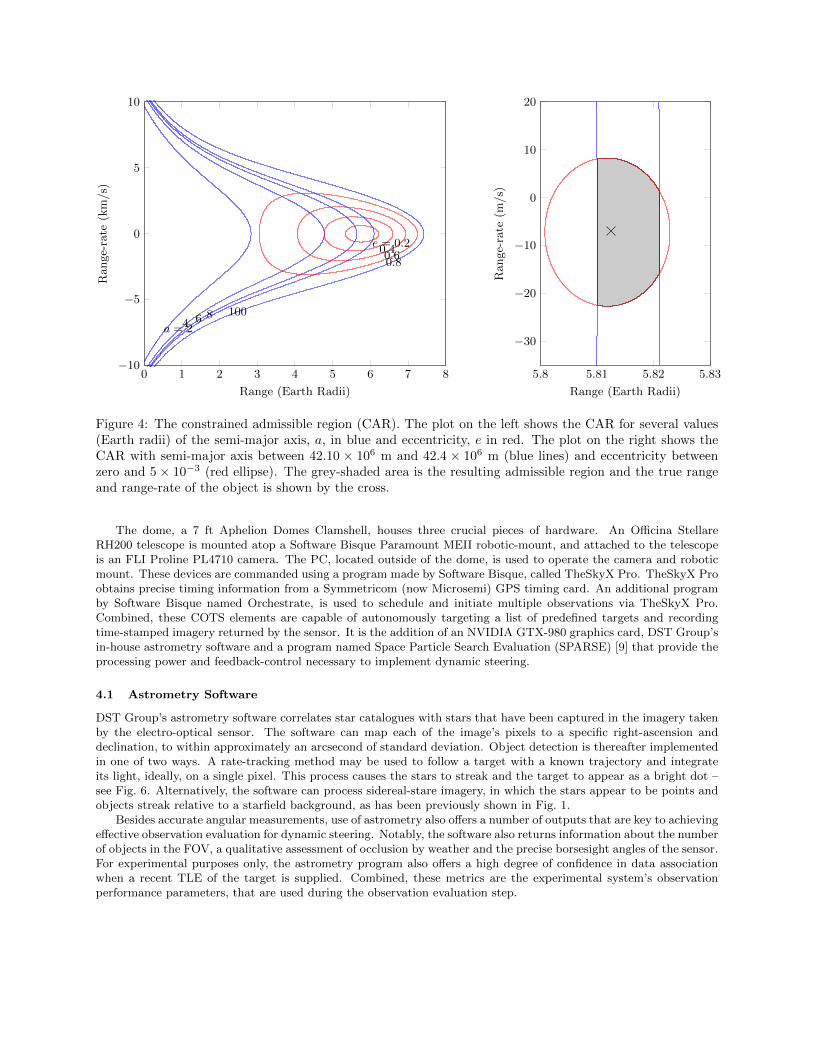
where µ⊕ is the Earth’s gravitational parameter and h = r× r is the object’s specific angular momentum vector. Asdepicted in Fig. 4, these equations can be rearranged to form a relationship between range and range-rate, providedconstraints to an orbit’s semi-major axis length, a [13], and eccentricity [16]. The specifics regarding the sensor-RSOgeometry necessary for generating Fig. 4 are discussed further in Section 5.
The density p(z|z0) and an assumed uniform distribution across the CAR may thereafter be combined to describethe six-dimensional distribution p(z|z0, a1 < a < a2, e1 < e < e2), based on the constraints a1 < a < a2 ande1 < e < e2. The distribution p(z|z0, a1 < a < a2, e1 < e < e2) = p(z|z0) can be subsequently transformed via anappropriate measurement model, x = h(z), to obtain the desired prior p(x|z0).
4. THE EXPERIMENTAL SYSTEM
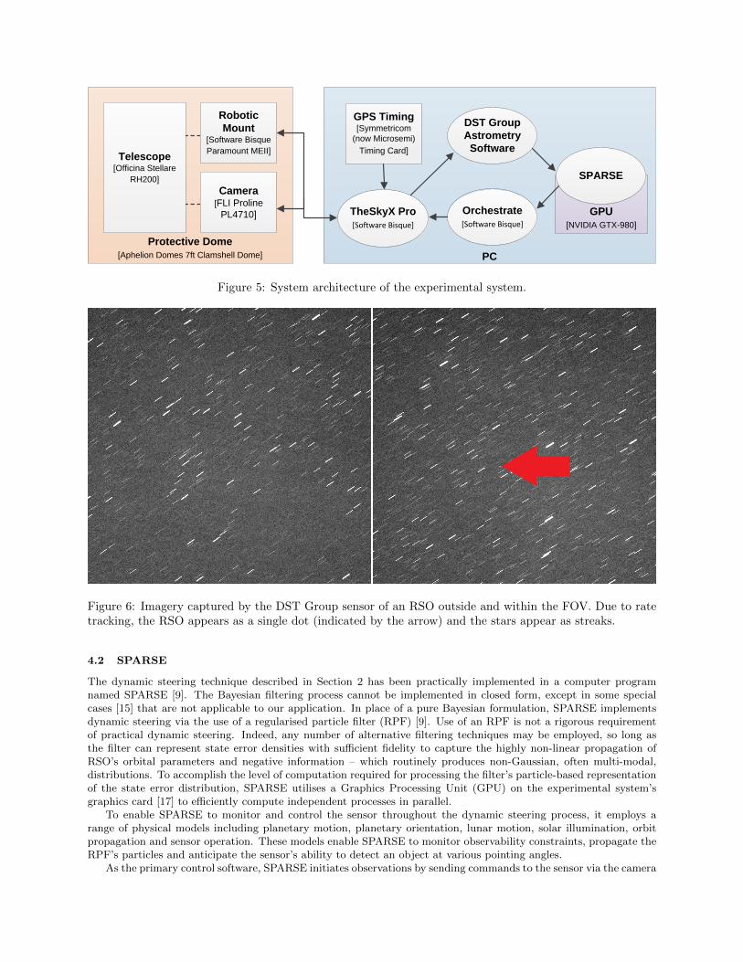
DST Group is currently developing a research facility for collaborative SSA experimentation. A robotic electro-opticalsensor belonging to this facility, located in Edinburgh, South Australia, has been augmented with a dynamic steeringcapability in a collaborative effort between DST Group and UQ. The system architecture of the experimental sensor isdisplayed in Fig. 5. The system is composed of two primary elements, a dome to mount and house the electro-opticalequipment and a PC to control the robotic telescope and implement dynamic steering.
0 1 2 3 4 5 6 7 8−10
−5
0
5
10
a = 246 8 100
e = 0.20.40.60.8
Range (Earth Radii)
Range-rate
(km/s)
5.8 5.81 5.82 5.83
−30
−20
−10
0
10
20
Range (Earth Radii)
Range-rate
(m/s)
Figure 1: The constrained admissible region (CAR). The figure on the left shows the CAR for several values(Earth radii) of the semi-major axis, a, in blue and eccentricity, e in red. The figure on the right shows theCAR with semi-major axis between 42.15 × 10⁶m and 42.2 × 10⁶m (blue lines) and eccentricity betweenzero and 10−3 (red ellipse). The grey-shaded area is the resulting admissible region and the true range andrange-rate of the object is shown by the cross.
Figure 4: The constrained admissible region (CAR). The plot on the left shows the CAR for several values(Earth radii) of the semi-major axis, a, in blue and eccentricity, e in red. The plot on the right shows theCAR with semi-major axis between 42.10 × 10⁶ m and 42.4 × 10⁶ m (blue lines) and eccentricity betweenzero and 5 × 10⁻³ (red ellipse). The grey-shaded area is the resulting admissible region and the true rangeand range-rate of the object is shown by the cross.
The dome, a 7 ft Aphelion Domes Clamshell, houses three crucial pieces of hardware. An Officina StellareRH200 telescope is mounted atop a Software Bisque Paramount MEII robotic-mount, and attached to the telescopeis an FLI Proline PL4710 camera. The PC, located outside of the dome, is used to operate the camera and roboticmount. These devices are commanded using a program made by Software Bisque, called TheSkyX Pro. TheSkyX Proobtains precise timing information from a Symmetricom (now Microsemi) GPS timing card. An additional programby Software Bisque named Orchestrate, is used to schedule and initiate multiple observations via TheSkyX Pro.Combined, these COTS elements are capable of autonomously targeting a list of predefined targets and recordingtime-stamped imagery returned by the sensor. It is the addition of an NVIDIA GTX-980 graphics card, DST Group’sin-house astrometry software and a program named Space Particle Search Evaluation (SPARSE) [9] that provide theprocessing power and feedback-control necessary to implement dynamic steering.
4.1 Astrometry Software
DST Group’s astrometry software correlates star catalogues with stars that have been captured in the imagery takenby the electro-optical sensor. The software can map each of the image’s pixels to a specific right-ascension anddeclination, to within approximately an arcsecond of standard deviation. Object detection is thereafter implementedin one of two ways. A rate-tracking method may be used to follow a target with a known trajectory and integrateits light, ideally, on a single pixel. This process causes the stars to streak and the target to appear as a bright dot –see Fig. 6. Alternatively, the software can process sidereal-stare imagery, in which the stars appear to be points andobjects streak relative to a starfield background, as has been previously shown in Fig. 1.
Besides accurate angular measurements, use of astrometry also offers a number of outputs that are key to achievingeffective observation evaluation for dynamic steering. Notably, the software also returns information about the numberof objects in the FOV, a qualitative assessment of occlusion by weather and the precise borsesight angles of the sensor.For experimental purposes only, the astrometry program also offers a high degree of confidence in data associationwhen a recent TLE of the target is supplied. Combined, these metrics are the experimental system’s observationperformance parameters, that are used during the observation evaluation step.
PC
Protective Dome
[Aphelion Domes 7ft Clamshell Dome]
Telescope[Officina Stellare
RH200]
TheSkyX Pro
[Software Bisque]
Orchestrate
[Software Bisque]
GPS Timing[Symmetricom
(now Microsemi)
Timing Card]
Camera[FLI Proline
PL4710]
Robotic
Mount[Software Bisque
Paramount MEII]
DST Group
Astrometry
Software
GPU
[NVIDIA GTX-980]
SPARSE
Figure 5: System architecture of the experimental system.
Figure 6: Imagery captured by the DST Group sensor of an RSO outside and within the FOV. Due to ratetracking, the RSO appears as a single dot (indicated by the arrow) and the stars appear as streaks.
4.2 SPARSE
The dynamic steering technique described in Section 2 has been practically implemented in a computer programnamed SPARSE [9]. The Bayesian filtering process cannot be implemented in closed form, except in some specialcases [15] that are not applicable to our application. In place of a pure Bayesian formulation, SPARSE implementsdynamic steering via the use of a regularised particle filter (RPF) [9]. Use of an RPF is not a rigorous requirementof practical dynamic steering. Indeed, any number of alternative filtering techniques may be employed, so long asthe filter can represent state error densities with sufficient fidelity to capture the highly non-linear propagation ofRSO’s orbital parameters and negative information – which routinely produces non-Gaussian, often multi-modal,distributions. To accomplish the level of computation required for processing the filter’s particle-based representationof the state error distribution, SPARSE utilises a Graphics Processing Unit (GPU) on the experimental system’sgraphics card [17] to efficiently compute independent processes in parallel.
To enable SPARSE to monitor and control the sensor throughout the dynamic steering process, it employs arange of physical models including planetary motion, planetary orientation, lunar motion, solar illumination, orbitpropagation and sensor operation. These models enable SPARSE to monitor observability constraints, propagate theRPF’s particles and anticipate the sensor’s ability to detect an object at various pointing angles.
As the primary control software, SPARSE initiates observations by sending commands to the sensor via the camera
and mount-control software to initiate rate-tracking observations. The resulting imagery is processed immediatelyby the DST Group astrometry software. Once evaluated, the observation and performance parameters are passed onto SPARSE to update the distribution and, if required, start the process over again.
5. SYSTEM TRIALS
A series of verification tests using the experimental system were conducted during field trials on 15th April 2015and again on the 10th June 2015, to ensure dynamic steering had been successfully implemented on the DST Groupsensor. Immediately after the success of these trials, imagery was collected to obtain simulated and experimentalverification of the proposed IOD method. The Beidou G1 satellite — US Catalogue ID: 36287 — was chosen as thetest target. Beidou G1 is routinely visible to Edinburgh and precision orbital data is available to guarantee dataassociation during this initial investigation. Beidou G1 was imaged from Edinburgh using the sidereal stare methodon 11th June 2015 at 10:52 UTC.
Whilst using a single image to obtain all measurements will be a case for future investigation, for this study,angular measurements were obtained from a single image while two consecutive images were used to obtain angularrate measurements. The distance between the midpoints of the streaks resulting from the satellite’s relative motionwere used to obtain a locally linearised angular rate and the measurement error was estimated via a Two-pointDifferencing method [18]. Using the Beidou G1 imagery, measurement error standard deviations of 2 arcseconds forangular measurements and 8.2× 10⁻³ arcseconds per second for their rates were estimated.
Unfortunately, subsequent verification of the imagery indicated that the measurements contained systematic errorsand were inappropriate for testing purposes. Furthermore, due to subsequent cloud cover and operational constraints,new observations could not be obtained for this paper. Nevertheless, the measurement error values are believed to beachievable by the system, once the systematic errors are eliminated and new imagery is obtained. The remainder ofthe section therefore details a simulated verification using equivalent simulated measurements and the measurementerror values identified in the trial.
A Beidou G1 two line element (TLE), published on 10th June 2015, was obtained to generate truth data for thesimulation. Topocentric angles and rates relative to Edinburgh were computed from the TLE. Gaussian error wasadded to simulate an appropriately noisy measurement and obtain p(z|z0). To generate the prior necessary to initiatedynamic steering, the process detailed in Section 3 was implemented by firstly sampling p(z|z0) to obtain angles andangle-rates. Thereafter the applicable CAR was computed and uniformly sampled to obtain a range and range-rate.The plot on the left of Fig. 4 displays the constant e and a contours that are produced when a sensor, located inEdinburgh, observes the Beidou G1 satellite on 11th June 2015 at 10:53 UTC. The plot on the right shows a morerepresentative CAR for the purposes of initial orbit determination, where the eccentricity and semi-major axis havebeen constrained to orbits in near-GEO. The near-GEO constraints chosen for this study are displayed in Table 1.The resulting six-dimensional samples were subsequently transformed into SPARSE’s preferred state-space, SDP4elements [19], to achieve a particle representation of the prior p(x|z0).
Table 1: Constraints used to define a GEO-like constrained admissible region.
Parameter Constraintsemi-major axis length 42102627 < a < 42384255 m
eccentricity 0 < e < 0.05
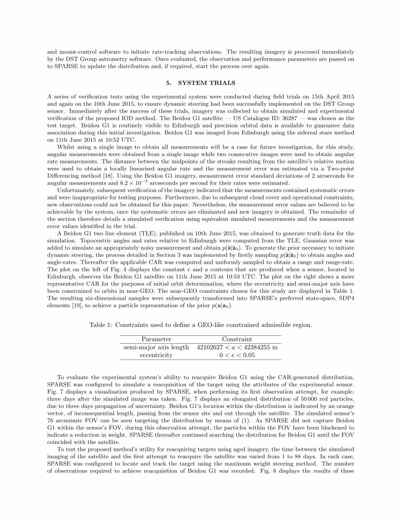
To evaluate the experimental system’s ability to reacquire Beidou G1 using the CAR-generated distribution,SPARSE was configured to simulate a reacquisition of the target using the attributes of the experimental sensor.Fig. 7 displays a visualisation produced by SPARSE, when performing its first observation attempt, for example,three days after the simulated image was taken. Fig. 7 displays an elongated distribution of 50 000 red particles,due to three days propagation of uncertainty. Beidou G1’s location within the distribution is indicated by an orangevector, of inconsequential length, passing from the sensor site and out through the satellite. The simulated sensor’s76 arcminute FOV can be seen targeting the distribution by means of (1). As SPARSE did not capture BeidouG1 within the sensor’s FOV, during this observation attempt, the particles within the FOV have been blackened toindicate a reduction in weight. SPARSE thereafter continued searching the distribution for Beidou G1 until the FOVcoincided with the satellite.
To test the proposed method’s utility for reacquiring targets using aged imagery, the time between the simulatedimaging of the satellite and the first attempt to reacquire the satellite was varied from 1 to 88 days. In each case,SPARSE was configured to locate and track the target using the maximum weight steering method. The numberof observations required to achieve reacquisition of Beidou G1 was recorded. Fig. 8 displays the results of these
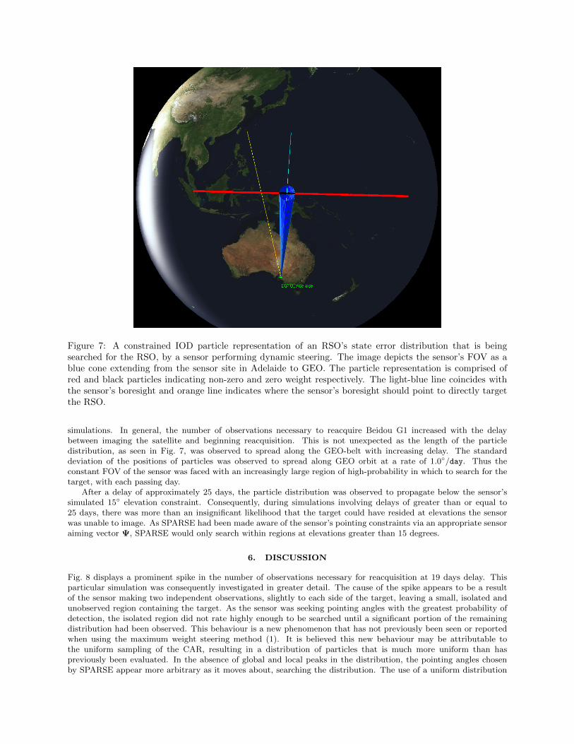
Figure 7: A constrained IOD particle representation of an RSO’s state error distribution that is beingsearched for the RSO, by a sensor performing dynamic steering. The image depicts the sensor’s FOV as ablue cone extending from the sensor site in Adelaide to GEO. The particle representation is comprised ofred and black particles indicating non-zero and zero weight respectively. The light-blue line coincides withthe sensor’s boresight and orange line indicates where the sensor’s boresight should point to directly targetthe RSO.
simulations. In general, the number of observations necessary to reacquire Beidou G1 increased with the delaybetween imaging the satellite and beginning reacquisition. This is not unexpected as the length of the particledistribution, as seen in Fig. 7, was observed to spread along the GEO-belt with increasing delay. The standarddeviation of the positions of particles was observed to spread along GEO orbit at a rate of 1.0◦/day. Thus theconstant FOV of the sensor was faced with an increasingly large region of high-probability in which to search for thetarget, with each passing day.
After a delay of approximately 25 days, the particle distribution was observed to propagate below the sensor’ssimulated 15◦ elevation constraint. Consequently, during simulations involving delays of greater than or equal to25 days, there was more than an insignificant likelihood that the target could have resided at elevations the sensorwas unable to image. As SPARSE had been made aware of the sensor’s pointing constraints via an appropriate sensoraiming vector Ψ, SPARSE would only search within regions at elevations greater than 15 degrees.
6. DISCUSSION
Fig. 8 displays a prominent spike in the number of observations necessary for reacquisition at 19 days delay. Thisparticular simulation was consequently investigated in greater detail. The cause of the spike appears to be a resultof the sensor making two independent observations, slightly to each side of the target, leaving a small, isolated andunobserved region containing the target. As the sensor was seeking pointing angles with the greatest probability ofdetection, the isolated region did not rate highly enough to be searched until a significant portion of the remainingdistribution had been observed. This behaviour is a new phenomenon that has not previously been seen or reportedwhen using the maximum weight steering method (1). It is believed this new behaviour may be attributable tothe uniform sampling of the CAR, resulting in a distribution of particles that is much more uniform than haspreviously been evaluated. In the absence of global and local peaks in the distribution, the pointing angles chosenby SPARSE appear more arbitrary as it moves about, searching the distribution. The use of a uniform distribution
Delay Until Requisition Attempt (days)
Num
ber
of O
bser
vatio
ns U
ntil
Rea
cqui
sitio
n
0 10 20 30 40 50 60 70 80 900
10
20
30
40
50
60
70
80
90
Figure 8: A plot of the number of observations required to locate the target relative to the age of the imageused to initialise the search. The red region indicates the delays in which the particle distribution propagatedbeyond the steering constraints of the sensor.
was nonetheless a naıve first choice and it is probable that the process would benefit from additional considerationregarding the likelihood of range and range-rates across the CAR. This aspect, along with alternative, more suitedsearch methodologies, will therefore be a point of future research.
The results of this initial investigation are nevertheless encouraging and motivate further attempts at field trials.In all test cases, the target was reacquired in spite of a lack of precise information regarding the target’s range andrange-rate, and the delay between obtaining imagery and attempting reacquisition. The proposed process enabledthe reacquisition of a simulated UCT as much as 3 months after it was briefly imaged. Furthermore, if the delaybetween imaging and reacquisition was less than 30 days, the target, in all but one case, was reacquired in less than5 observations.
As a preliminary study, it was desirable to learn if objects can be reacquired via this approach whilst neglectingthe significant role effective data association will almost certainly play. Clearly, this approach could result in furtherdetections of UCTs and will likely require the incorporation of real-time data-association when objects are detected.
REFERENCES
[1] National Research Council of the National Academies, Continuing Kepler’s Quest: Assessing Air Force SpaceCommand’s Astrodynamics Standards. The National Academies Press, 2012.
[2] M. Wasson, “Space situational awareness in the Joint Space Operations Center,” in Air Force Air and SpaceOperations Center (614th) Peterson AFB Co., 2011.
[3] T. Kelecy and M. Jah, “Analysis of orbit prediction sensitivity to thermal emissions acceleration modeling for higharea-to-mass ratio (HAMR) objects,” in Proc. the Advanced Maui Optical and Space Surveillance TechnologiesConf., (AMOS), 2009.
[4] D. F. Woods, R. Y. Shah, J. A. Johnson, A. Szabo, E. C. Pearce, R. L. Lambour, and W. J. Faccenda, “Spacesurveillance telescope: focus and alignment of a three mirror telescope,” Optical Engineering, vol. 52, no. 5, pp.053 604–053 604, 2013.
[5] N. Singh, J. T. Horwood, J. M. Aristoff, A. B. Poore, C. Sheaff, and M. K. Jah, “Multiple hypothesis tracking(mht) for space surveillance: Results and simulation studies,” DTIC Document, Tech. Rep., 2013.

[6] M. J. Holzinger, K. K. Luu, C. Sabol, and K. Hill, “Probabilistic tracklet characterization and prioritizationusing admissible regions,” in Proceedings of the 2014 Advanced Maui Optical and Space Surveillance TechnologiesConference, Wailea, Maui, Hawaii, 2014.
[7] T. A. Hobson and I. V. L. Clarkson, “A Particle-based Search Strategy for Improved Space Situational Aware-ness,” 3-6 Nov 2013, accepted in Asilomar Conf. on Signals Systems, and Computers.
[8] ——, “An experimental implementation of a particle-based dynamic sensor steering method for tracking andsearching for space objects,” 4-9 May 2014, accepted in proceedings of IEEE International Conference on Acous-tics, Speech and Signal Processing (ICASSP).
[9] T. A. Hobson, “Sensor management for enhanced catalogue maintenance of resident space objects,” Ph.D. thesis,The University of Queensland, 2015.
[10] W. Koch, “On negativeinformation in tracking and sensor data fusion: Discussion of selected examples,” inProceedings of the Seventh International Conference on Information Fusion, vol. 1. IEEE Publ. Piscataway,NJ, 2004, pp. 91–98.
[11] J. Hoffman, M. Spranger, D. Gohring, and M. Jungel, “Making use of what you don’t see: Negative informationin markov localization,” in Intelligent Robots and Systems, 2005.(IROS 2005). 2005 IEEE/RSJ InternationalConference on. IEEE, 2005, pp. 2947–2952.
[12] K. Poole, J. Woloschek, E. Murphy, J. Lefever, and J. Breslin, “Strategies for optimizing geo debris search,” inThe Advanced Maui Optical and Space Surveillance Technologies Conference, vol. 1, 2006, p. 66.
[13] K. J. DeMars, M. K. Jah, and P. W. Schumacher Jr, “Initial orbit determination using short-arc angle and anglerate data,” Aerospace and Electronic Systems, IEEE Transactions on, vol. 48, no. 3, pp. 2628–2637, 2012.
[14] S. Haykin, Adaptive Filter Theory, 3rd ed. Upper Saddle River, New Jersey: Prentice-Hall, 1996.
[15] B. Ristic, S. Arulampalam, and N. Gordon, Beyond the Kalman Filter. Artech House, 2004.
[16] K. J. DeMars and M. K. Jah, “Probabilistic initial orbit determination using gaussian mixture models,” Journalof Guidance, Control, and Dynamics, vol. 36, no. 5, pp. 1324–1335, 2013.
[17] T. A. Hobson and I. V. L. Clarkson, “GPU-based space situational awareness simulation utilising parallelism forenhanced multi-sensor management,” in Proc. the Advanced Maui Optical and Space Surveillance TechnologiesConf., (AMOS), 2012.
[18] Y. Bar-Shalom, X. R. Li, and T. Kirubarajan, Estimation with applications to tracking and navigation: theoryalgorithms and software. John Wiley & Sons, 2004.
[19] D. A. Vallado, P. Crawford, R. Hujsak, and T. S. Kelso, “Revisiting spacetrack report #3,” Aug 2006.