DS-15079 (Replaces DS-15049) DEVELOPMENTAL ...DS-15079, Page 3 of 12 3. Engineer may determine and...
12
DS-15079 (Replaces DS-15049) DEVELOPMENTAL SPECIFICATIONS FOR PRIMARY AND INTERSTATE PAVEMENT SMOOTHNESS Effective Date December 17, 2019 THE STANDARD SPECIFICATIONS, SERIES 2015, ARE AMENDED BY THE FOLLOWING MODIFICATIONS AND ADDITIONS. THESE ARE DEVELOPMENTAL SPECIFICATIONS AND THEY SHALL PREVAIL OVER THOSE PUBLISHED IN THE STANDARD SPECIFICATIONS. These specifications replace Section 2317 of the Standard Specifications. 2317.01 GENERAL. Evaluate pavement smoothness for Interstate and Primary main line pavement surfaces, and other road surfaces included on Primary projects, except when specifically excluded or modified by the contract documents. Main line pavement is defined as permanent pavement for through lanes. A. Index used for determining the pavement smoothness is the Mean Roughness Index (MRI) per segment as determined by latest version of the FHWA’s software, ProVAL. B. The other measure of pavement smoothness is the Area of Localized Roughness (ALR) based on a continuous MRI computed over a 25 foot distance as determined by latest version of ProVAL. C. A pavement segment is defined as a continuous area of finished pavement 0.1 mile in length and one lane (10 to 12 foot nominal) in width. A partial segment may result from an interruption of the continuous pavement surface (in other words, bridge approaches, side road tie-ins, the completion of the daily paving operations, and so forth). Pay adjustments will be prorated for partial segments. If a segment is less than 100 feet in length and requires corrective work, Engineer will waive corrective work requirement for segment and instead assess a prorated disincentive. Contracting Authority will subject the segment to ALR correction in accordance with Table 2317.05-1 2317.02 EQUIPMENT. A. Provide and operate an inertial profiler meeting the requirements of AASHTO M 328 and Materials I.M. 341, Appendix A. Ensure operator is trained and certified to operate profiler as required by the Contracting Authority. B. For corrective work by diamond grinding, use grinding and texturing equipment meeting the requirements of Section 2532 of the Standard Specifications.
Transcript of DS-15079 (Replaces DS-15049) DEVELOPMENTAL ...DS-15079, Page 3 of 12 3. Engineer may determine and...

DS-15079 (Replaces DS-15049)
DEVELOPMENTAL SPECIFICATIONS FOR
PRIMARY AND INTERSTATE PAVEMENT SMOOTHNESS
Effective Date December 17, 2019
THE STANDARD SPECIFICATIONS, SERIES 2015, ARE AMENDED BY THE FOLLOWING MODIFICATIONS AND ADDITIONS. THESE ARE DEVELOPMENTAL SPECIFICATIONS AND THEY SHALL PREVAIL OVER THOSE PUBLISHED IN THE STANDARD SPECIFICATIONS. These specifications replace Section 2317 of the Standard Specifications. 2317.01 GENERAL. Evaluate pavement smoothness for Interstate and Primary main line pavement surfaces, and other road surfaces included on Primary projects, except when specifically excluded or modified by the contract documents. Main line pavement is defined as permanent pavement for through lanes.
A. Index used for determining the pavement smoothness is the Mean Roughness Index (MRI) per
segment as determined by latest version of the FHWA’s software, ProVAL.
B. The other measure of pavement smoothness is the Area of Localized Roughness (ALR) based on a continuous MRI computed over a 25 foot distance as determined by latest version of ProVAL.
C. A pavement segment is defined as a continuous area of finished pavement 0.1 mile in length and one lane (10 to 12 foot nominal) in width. A partial segment may result from an interruption of the continuous pavement surface (in other words, bridge approaches, side road tie-ins, the completion of the daily paving operations, and so forth). Pay adjustments will be prorated for partial segments. If a segment is less than 100 feet in length and requires corrective work, Engineer will waive corrective work requirement for segment and instead assess a prorated disincentive. Contracting Authority will subject the segment to ALR correction in accordance with Table 2317.05-1
2317.02 EQUIPMENT.
A. Provide and operate an inertial profiler meeting the requirements of AASHTO M 328 and Materials I.M. 341, Appendix A. Ensure operator is trained and certified to operate profiler as required by the Contracting Authority.
B. For corrective work by diamond grinding, use grinding and texturing equipment meeting the requirements of Section 2532 of the Standard Specifications.

DS-15079, Page 2 of 12
2317.03 TESTING AND EVALUATION.
A. Testing.
1. Obtain profiles of both wheel paths for each lane according to procedures shown in Materials I.M. 341, Appendix A. Wheel paths are defined as 3 feet and 9 feet from the center line or lane line. Average the two wheel path profile indexes for each segment.
2. Engineer may use an inertial profiler, 10 foot straightedge, or other means to detect irregularities in excluded surface areas or areas outside the required wheel paths for required corrective action.
3. Test bridge approaches according to Section 2428 of the Standard Specifications.
4. Test pavement within 5 working days of completion of paving.
5. Paved shoulders will be excluded from smoothness testing. When used as a temporary driving surface, evaluate paved shoulders for ALR. Take corrective action for ALR greater than 250.0 inches/mile.
B. Evaluation.
1. Determine a MRI using the latest version of the ProVAL “Ride Quality” analysis and following procedures shown in Materials I.M. 341, Appendix A for each segment of finished pavement surface with a posted speed over 45 mph except for: a. Roads intersecting the mainline pavement less than 600 feet in length. b. Road connections 150 feet before an intersection that end at a stop sign (or a yield sign
at roundabouts). c. Twenty feet on either side of bridges, bridge approaches, existing EF joints, manholes, or
water valve boxes in the lane that the obstruction is located. d. Ramps and loops. e. Bridge approaches (evaluated according to Section 2428 of the Standard Specifications). f. Storage lanes, turn lanes, and other auxiliary lanes less than 1000 feet. g. Pavement less than 8.5 feet in width. h. Single lift pavement overlays 2 inches thick or less, unless the existing surface has been
corrected by milling or scarification. i. Single lift pavement overlays 2 inches thick or less placed directly on PCC pavement. j. Paved shoulders. k. Detour pavement. l. Crossovers. m. Individual sections of pavement less than 100 feet in length.
2. Determine ALR using the latest version of the ProVAL “Smoothness Assurance” analysis and following the procedures shown in Materials I.M. 341, Appendix A, for each segment of finished pavement surface with a posted or advisory speed over 35 mph except for: a. Side road connections 150 feet before an intersection that end at a stop sign (or a yield
sign at roundabouts). b. Twenty feet on either side of bridges, bridge approaches, manholes, or water valve boxes
in the lane that the obstruction is located. c. Bridge approaches (evaluated according to Section 2428 of the Standard Specifications). d. Pavement less than 8.5 feet in width. e. Paved shoulders (unless used as a temporary driving surface). f. Detour pavement. g. Crossovers. h. Individual sections of pavement less than 50 feet in length.

DS-15079, Page 3 of 12
3. Engineer may determine and identify irregularities of 1/8 inch or more in 10 feet longitudinally for excluded surface areas or areas outside required wheel paths.
4. Submit final profile summary sheets to the Engineer within 14 calendar days following completion of paving on project. When testing is done at completion of paving on project, provide Engineer ProVal files along with profile summary sheets.
2317.04 CORRECTIVE ACTIONS.
A. General.
1. Pavement will be evaluated in 0.1 mile segments using inertial profiler, to determine pavement segments where corrective work or pay adjustments will be necessary.
2. Within each 0.1 mile segment, correct ALR greater than 250.0 Inches/mile regardless of MRI value. Take corrective action.
3. Separately identify ALR.
4. On lanes over 8.5 feet in width, for through traffic which requires matching the surface of new pavement to the surface of an existing pavement, determine MRI and ALR for the existing lane. Compare MRI values and ALR areas according to Materials I.M. 341, Appendix A. If MRI and ALR for new pavement are less than the MRI and ALR for the existing surface, no negative payment adjustment or correction for MRI or ALR will be required.
B. MRI Correction.
Correct 0.1 mile segments having an initial MRI greater than those tolerances shown in Article 2317.05. Correct these segments to reduce MRI to that shown in Tables 2317.05-2 and 2317.05-3. Contractor has the option to replace these segments. On segments where corrections are made, test entire 0.1 mile segment of pavement to verify that corrections have met the MRI as shown in Tables 2317.05-2 and 2317.05-3.
C. ALR Correction. Correct ALR greater than those tolerances shown in Article 2317.05. Correct these segments to reduce the ALR to that shown in Table 2317.05-1. Contractor has the option to replace these areas. On segments where corrections are made, test entire 0.1 mile segment of pavement to verify corrections have met ALR level shown in Table 2317.05-1.
D. Engineer Identified Irregularities. Correct areas over 1/8 inch in 10 feet identified by Engineer.
E. Bridge Approach Sections.
Correct bridge approach sections according to Section 2428 of the Standard Specifications. F. Corrective Work.
When Contractor is not responsible for adjoining surface, ALR in the 20 feet at the end of a section will be reviewed by Engineer. Correct ALR determined to be under the control of Contractor and resulting from Contractor’s operations. Correction of ALR determined to be beyond control of Contractor will be paid according to Article 1109.03, B of the Standard Specifications. Complete corrective work prior to determining pavement thickness. Do not use bush hammers or other impact devices. 1. PCC Pavement.
Make corrections using an approved profiling device or by removing and replacing pavement. Apply corrective methods to full lane width. Ensure, when completed, corrected area (full lane width) has uniform texture and appearance, with the beginning and ending of the corrected

DS-15079, Page 4 of 12
area squared normal to centerline of paved surface. Where surface corrections are made, grooving will not be required.
2. HMA Pavement. a. Make corrections by diamond grinding, overlaying, replacing, or inlaying the area. If
surface is corrected by diamond grinding, perform same work and use same equipment as specified for PCC pavement.
b. If surface is corrected by overlay, replacement, or inlay; begin and end surface correction with a transverse saw cut normal to pavement lane lines or edge lines within any one area. Profile of surface shall be smooth with no bumps or dips at beginning or end of correction.
c. Overlay correction shall be for entire pavement width. Pavement cross slope shall be maintained through corrected areas.
G. Verification Testing.
1. Engineer will perform verification testing to validate Contractor’s certified quality control
testing. If Engineer’s verification test results validate Contractor’s test results, Contractor’s results will be used for acceptance. Disputes between Contractor’s and Engineer’s test results will be resolved according to Materials I.M. 341, Appendix A.
2. Engineer may test entire project length if it is determined Contractor’s certified test results are inaccurate. Contractor will be charged for this work at a rate of $800.00 per lane-mile, with a minimum charge of $1500.00.
3. Furnishing inaccurate tests may result in decertification of Contractor's certified operator.
2317.05 PAY ADJUSTMENTS.
A. General.
1. Pay adjustments will be based on initial MRI determined for the segments prior to performing any corrective work. Areas excluded from Inertial profiler testing and bridges approaches will not be subject to price adjustments.
2. If Contractor elects to remove and replace segments, Contractor will be paid the price
adjustment that corresponds to the initial index obtained on the pavement segments after replacement.
3. When the plans indicate an area of pavement shall be hand finished, the area will not be
subject to reduced payment. However, the area shall be profiled and corrected as necessary to meet these specifications.
B. Areas of Localized Roughness. Payment for areas of localized roughness will be adjusted as shown in Table 2317.05-1.
Table 2317.05-1: Schedule for Adjustment Payment for Areas of Localized Roughness
ALR in 25 Foot Continuous Mean International Roughness
Index (MRI) Inches per mile
Dollars per foot of pavement length per lane
200.0 to 250.0 -30.00 or grind* Greater than 250.0 Grind*
*Correct these areas to below 200.0 inches per mile

DS-15079, Page 5 of 12
C. PCC Pavement. Payment for mean International Roughness Index for PCC pavement will be adjusted as shown in Table 2317.05-2.
Table 2317.05-2: Schedule for Adjustment Payment for PCC Pavements
Mean International Roughness Index (MRI)
Inches per mile Dollars per 0.1 mile segment per
lane
Less than 55.0 1500.00 55.0 to 63.0 11812.5 - 187.5 X MRI 63.0 to 75.0 0.00 75.0 to 90.0 7500 – 100 X MRI or grind*
Greater than 90.0 Grind* *Correct these areas to below 75.0 inches per mile
D. HMA Pavement.
The payment for mean International Roughness Index for HMA pavement will be adjusted as shown in Table 2317.05-3.
Table 2317.05-3: Schedule for Adjustment Payment for HMA Pavements
Mean International Roughness Index (MRI)
Inches per mile Dollars per 0.1 mile segment per
lane
Less than 30.0 1500.00 30.0 to 39.0 6500 - 166.6667 X MRI 39.0 to 75.0 0.00 75.0 to 90.0 7500 – 100 X MRI or grind*
Greater than 90.0 Grind* *Correct these areas to below 75.0 inches per mile

DS-15079, Page 6 of 12
Materials I.M. 341IRI
Appendix A DETERMINING PAVEMENT RIDE QUALITY
SCOPE This IM describes procedures used to perform smoothness testing on new pavements surfaces. A certified person is required to perform the testing, evaluation, and reporting. PROCEDURE A. Apparatus
1. Inertial Profiler meeting requirements of AASHTO M 328 (this requires an auto start/stop) and currently certified on Iowa DOT test strips or other state test strips approved by Iowa DOT. For surfaces other than dense graded HMA, a large footprint laser is required.
2. Ten-foot straight edge or a 10-foot straight edge software simulation. 3. Distance measuring wheel or tape. 4. Latest version of ProVAL software. http://www.roadprofile.com/proval-software/current-version/
5. Latest version of the Iowa DOT Spreadsheet, Profile Summary Sheet.
http://www.iowadot.gov/Construction_Materials/materials_forms.html https://iowadot.gov/Construction_Materials/materialsforms/ProfileSummarySheet.xlsx
B. Profiler Approval
1. Profilers will be checked and approved by Iowa DOT Materials Laboratory before each construction season for proper operation. Profilers checked and approved in another state in the current year may be approved. Submit a request to Special Investigations Engineer for consideration of approval.
2. ProVAL will be used to analyze the profiler files. Criteria for approval includes:
a) High pass and low pass filters set to 0. Other settings according to manufacturer’s recommendation (Settings used for approval shall be the same used throughout the season).
b) Submittal of 5 good runs of the test strip as ERD files. c) DMI distance shall be within 0.15% of actual test strip distance. d) Equipment repeatability score with IRI filter shall be 0.90 or greater. e) Equipment accuracy score with the IRI filter shall be 0.88 or greater when compared to
reference profiler. f) Average IRI shall be within 5% of reference profiler IRI.
Office of Construction & Materials

DS-15079, Page 7 of 12
Materials I.M. 341IRI
C. Calibration and Verifications
Checks, calibrations, and verification of subsystems vary by manufacturer. Follow manufacturer’s recommended procedures and frequencies to ensure proper profile collection. D. Test Procedure
1. Contractor (or sub-contractor) responsible for smoothness testing shall give Engineer and District Materials Engineer 48 hour notice prior to testing so District Materials Office may provide verification testing.
2. Dirt and debris may affect collection of the profile. Excessive mud or caked mud shall be removed
prior to testing. A grader blade or power broom will knock concrete crumbs off longitudinal or transverse grooving.
3. Perform warm up and checks of profiler. a) For most profilers, tire pressures should be maintained at the same pressures as when the
distance was last calibrated. b) It is advisable to do a bounce test and vertical height test on sensors before beginning
testing. 4. Ensure computer settings are the same as when the unit was approved by Department. High-pass
and low pass filter settings should be “0”.
5. Test in direction of traffic whenever possible.
6. Test unit positioning.
a) Perform testing with sensors in wheel paths, 3 feet and 9 feet from centerline or lane line, for lanes 11 feet to 12 feet wide unless noted otherwise in the contract documents.
b) For testing on wider lanes such as ramps and loops, position driver side sensor 3 feet from left edge line. If passenger side sensors are within 1 foot of a longitudinal joint, adjust travel path to the right so sensor is 2 feet from joint line.
c) For testing tapers to and from a full lane, begin or end section testing when pavement is
either 12 feet or at full lane width whichever is less.
d) Begin collecting profile data for ALR 50 feet before beginning header from old to new surface and 50 feet beyond header from new to old surface. Figure 1
e) Figure 2 and 3 show examples of how to analyze ALR at obstructions defined in Article
2317.03, B, 2, b of the Standard Specifications.
DS-15079, Page 8 of 12
Materials I.M. 341IRI
7. Ensure there is enough room before and after section to be tested to allow for a 300 foot run-in
and run-out area for the profiler before and after the test section according to manufacturer’s recommendations. The run-in allows accelerometers, lasers, and computer to stabilize before start of the section. Mark intended start and stop location of section and place reflective cones or strips to trigger auto start/stop sensor on profiler.
8. Use event feature to mark on the file reference points like, side road intersections, roadway signs,
maintenance markers, stations markers, and mileposts. In the event of rough segments or ALR, this will help the grinding personnel locate the area to grind. (The as driven stationing from profiler will rarely match stationing on roadway unless roadway is completely flat with no curves. The longer the run of the profiler, the farther the profiler stationing will be off from plan stationing.)
9. During the profiler run, use the ignore feature at bridges and bridge approaches to mark areas on the
file and exclude the data from the analysis. Profiler still collects data and it can be recovered later during analysis if the key is pressed inadvertently.
10. Label file so it can be easily found and retrieved later. (Project number, lane, and beginning station in file name is one way to label)
11. When a segment is corrected by grinding to improve the segment MRI, entire segment shall be
retested and MRI determined to verify the corrected segment is in specification compliance.
E. Analyzing and Reporting 1. Use profiler software export function to export an unfiltered “ERD” file.
2. Use latest version of ProVAL to perform MRI and ALR analysis on ERD files.
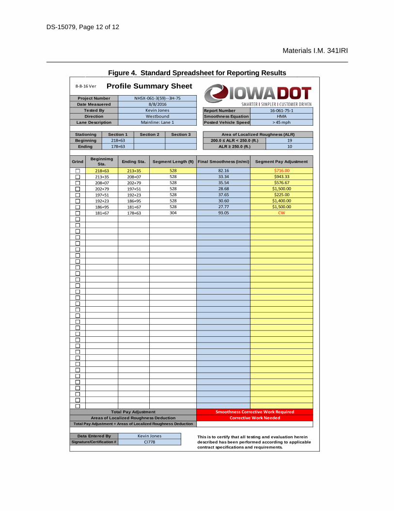
3. Report results on Iowa DOT provided Excel spreadsheet (Figure 4). Sheet may be downloaded at
http://www.iowadot.gov/Construction_Materials/materials_forms.html https://iowadot.gov/Construction_Materials/materialsforms/ProfileSummarySheet.xlsx. Test report is required on this form for project acceptance.
4. Areas needing correction will be noted by the software on the spreadsheet. For segments that are ground to correct MRI, show corrected MRI and mark the box to the left of the segment to show grinding has been completed on that spreadsheet.
5. There are two types of reports:
a) Final. Used to indicate that report is being submitted for acceptance. b) Corrected. Used to indicate that there was either an error in original test report or that the
section was corrected by grinding and retested.
6. Test report laboratory numbers shall be continuous and increasing numerically as each succeeding test is performed. Laboratory numbers shall have a letter added to the end of the original laboratory number for corrected reports (i.e., original report number 01-218L-05, corrected report number 01-218L-05-A).

DS-15079, Page 9 of 12
Materials I.M. 341IRI
7. Submit final and corrected reports to Engineer through DocExpress. If smoothness testing is done
after paving is completed, submit ProVAL file(s) to DocExpress also. Label ProVAL file(s) with the project as part of file name.
8. Keep ProVAL files not submitted to DocExpress until validation of Contractor test results have been confirmed.
9. An example of a completed report form is shown in Figure 4.
F. Certification
Use trained and certified person to do testing, evaluation, and reporting. Certification information is in Materials I.M. 213.
VALIDATION OF CONTRACTOR TEST RESULTS To use Contractor test results in acceptance decision, results must be validated. Normally District Materials Office will perform verification testing within 1 month from receiving final test reports and notification from Contractor that pavement is available for testing. Validation tolerances are in Materials I.M. 216.
Contractor test results that cannot be validated, District Materials Office will promptly notify Contractor and begin dispute resolution process. Testing disputes arising between the Contracting Agency and Contractor shall be resolved in a reliable, unbiased manner. This may involve an evaluation performed by the Iowa DOT Central Materials Laboratory. Resolution decisions by Iowa DOT Central Materials Laboratory will be final.
District Materials Engineer will select some or all of the following steps for dispute resolution:
1. Check numbers and calculations. 2. Review testing procedures. 3. Compare profiles and dates of testing. 4. Check equipment operation, calibrations, and tolerances. 5. Perform side-by side tests. 6. Involve Central Materials Laboratory.
If discrepancy cannot be resolved using steps listed above, or if it is determined that Contractor’s testing is in error, then Agency test results will be used for acceptance decision for project.

DS-15079, Page 10 of 12
Materials I.M. 341IRI

DS-15079, Page 11 of 12
Materials I.M. 341IRI
DS-15079, Page 12 of 12
Materials I.M. 341IRI
Figure 4. Standard Spreadsheet for Reporting Results
Report Number 16-061-75-1
This is to certify that all testing and evaluation herein described has been performed according to applicable contract specifications and requirements.
Grind Beginnimg Sta. Ending Sta. Segment Length (ft) Final Smoothness (in/mi) Segment Pay Adjustment
Smoothness EquationPosted Vehicle Speed
Area of Localized Roughness (ALR)200.0 ≤ ALR < 250.0 (ft.)
ALR ≥ 250.0 (ft.)
HMA> 45 mph
1910
BeginningEnding
218+63178+63
Project NumberDate Measuered
Tested ByDirection
Lane Description
Section 1
NHSX-061-3(59)--3H-758/8/2016
Kevin JonesWestbound
Mainline: Lane 1
Section 2 Section 3Stationing
192+23186+95181+67
218+63213+35208+07202+79197+51
186+95181+67178+63
213+35208+07202+79197+51192+23
528528528528304
528 82.16 $716.00528528
$943.33$576.67
33.3435.5428.6837.6530.6027.7793.05
$1,500.00$225.00
$1,400.00$1,500.00
CW
8-8-16 Ver Profile Summary Sheet
Smoothness Corrective Work RequiredCorrective Work Needed
Data Entered BySignature/Certification #
Kevin JonesCI778
Total Pay AdjustmentAreas of Localized Roughness Deduction
Total Pay Adjustment + Areas of Localized Roughness Deduction