Edital com as regas e relação dos candidatos que concorrem ao

CLASSIFICATION NOTES
No. 61.3
The content of thprohibited by anissuance of certi
chargeable, w
REGASIFICATION VESSELS
MAY 2011
DET NORSKE VERITAS
Veritasveien 1, NO-1322 Høvik, Norway Tel.: +47 67 57 99 00 Fax: +47 67 57 99 11
is service document is the subject of intellectual property rights reserved by Det Norske Veritas AS (DNV). The user accepts that it is yone else but DNV and/or its licensees to offer and/or perform classification, certification and/or verification services, including the
ficates and/or declarations of conformity, wholly or partly, on the basis of and/or pursuant to this document whether free of charge or ithout DNV's prior written consent. DNV is not responsible for the consequences arising from any use of this document by others.
FOREWORD
DET NORSKE VERITAS (DNV) is an autonomous and independent foundation with the objectives of safeguarding life,property and the environment, at sea and onshore. DNV undertakes classification, certification, and other verification andconsultancy services relating to quality of ships, offshore units and installations, and onshore industries worldwide, andcarries out research in relation to these functions.
Classification NotesClassification Notes are publications that give practical information on classification of ships and other objects. Examplesof design solutions, calculation methods, specifications of test procedures, as well as acceptable repair methods for somecomponents are given as interpretations of the more general rule requirements.
All publications may be downloaded from the Society’s Web site http://www.dnv.com/.
The Society reserves the exclusive right to interpret, decide equivalence or make exemptions to this Classification Note.
Background
As an alternative to onshore production of gas where liquid natural gas delivered from a LNG Carrier isvaporized to produce natural gas for consumption this process can take place onboard a purposed built vessellocated offshore. In areas where it is proven difficult to obtain permission to build new onshore terminals dueto environmental or safety restrictions such a concept enabling offshore gas production can be an option.
In order to vaporize the liquid gas onboard a vessel Regasification plants must be installed and means forunloading the vaporized gas need to be provided. Unloading could be arranged via a submerged turret buoydelivering to a subsea pipe grid or through dedicated gas export manifolds connected to a receiving installationplaced on an external platform, jetty or similar.
Classification Note 61.3 is applicable for all vessels engaged in regasification operation. This includes bothpermanently moored LNG carriers doing more or less continuous regasification of LNG received from shuttletankers and LNG carriers involved in both trading and periodically regasification operation.The class notationREGAS will be given upon demonstrated compliance with recommendation outlined in this Note. It is intendedto introduce requirements for regasification vessel in DNV’s Rules for Classification of Ships after gainingfurther experiences with such installations.
Main changes
The main changes are:
— Requirements for fire detection in the regasification plant area have been included.— Requirements for water spray/deluge system have been extended so that water monitors are no longer required. — Requirements for emergency de-pressurization/blow-down of the regasification system have been clarified.— Requirements for Process Shut Down have been defined.— Interactions between the vessel’s emergency shut down system (ESD) required by the IGC Code and the
emergency de-pressurization/blow down system and Process Shut Down System for the regasificationplant have been clarified.
— Requirements for heating systems for regasification vaporisers have been detailed.— Requirements for escape from the regasification area have been included.— Requirements/guidance for necessary monitoring and control systems have been expanded and clarified.— Requirements associated with ship-to-ship transfer of LNG in the case of permanently moored
regasification vessels have been addressed.— Requirements for testing and commissioning have been included.
The electronic pdf version of this document found through http://www.dnv.com is the officially binding version© Det Norske Veritas
Any comments may be sent by e-mail to [email protected] subscription orders or information about subscription terms, please use [email protected] Typesetting (Adobe Frame Maker) by Det Norske Veritas
If any person suffers loss or damage which is proved to have been caused by any negligent act or omission of Det Norske Veritas, then Det Norske Veritas shall pay compensation tosuch person for his proved direct loss or damage. However, the compensation shall not exceed an amount equal to ten times the fee charged for the service in question, provided thatthe maximum compensation shall never exceed USD 2 million.In this provision "Det Norske Veritas" shall mean the Foundation Det Norske Veritas as well as all its subsidiaries, directors, officers, employees, agents and any other acting on behalfof Det Norske Veritas.

Classification Notes - No. 61.3, May 2011
Page 3
CONTENTS
1. General.................................................................................................................................................... 41.1 Introduction...............................................................................................................................................41.2 Scope.........................................................................................................................................................41.3 Definitions.................................................................................................................................................4
2. Application.............................................................................................................................................. 42.1 Requirements ............................................................................................................................................42.2 Class Notations .........................................................................................................................................42.3 Documentation..........................................................................................................................................5
3. Piping design........................................................................................................................................... 5
4. Materials, Manufacture, Inspection and Testing................................................................................ 64.1 Materials ...................................................................................................................................................64.2 Piping design and manufacture.................................................................................................................64.3 Certification of components......................................................................................................................64.4 Strength and tightness testing ...................................................................................................................7
5. General Safety ........................................................................................................................................ 75.1 Risk assessment ........................................................................................................................................75.2 Classification and extent of Hazardous area ............................................................................................75.3 Cryogenic Releases...................................................................................................................................85.4 Fire Safety.................................................................................................................................................85.5 Physical protection of regasification units ................................................................................................85.6 Gas detection.............................................................................................................................................95.7 Heating system for LNG vaporisers .........................................................................................................95.8 Escape .......................................................................................................................................................9
6. Process Safety ......................................................................................................................................... 96.1 General......................................................................................................................................................96.2 Process Shut-Down System (PSD) ...........................................................................................................96.3 ESD...........................................................................................................................................................96.4 Blow down system..................................................................................................................................106.5 Pressure relief..........................................................................................................................................106.6 Vent system.............................................................................................................................................106.7 Monitoring systems.................................................................................................................................10
7. Functional requirements .................................................................................................................... 117.1 Start-up procedure...................................................................................................................................117.2 Operational .............................................................................................................................................117.3 Survey requirements for the in-service phase.........................................................................................12
8. Implications on Ship Design................................................................................................................ 128.1 Environmental conditions .......................................................................................................................128.2 Sloshing...................................................................................................................................................128.3 Structural support of regasification equipment on deck .........................................................................128.4 Gas detection in air inlets to the accommodation ...................................................................................128.5 Ship to ship transfer ................................................................................................................................12
9. Arrangement for submerged turret offloading................................................................................. 12
10. Testing and Commissioning ................................................................................................................ 1310.1 Alarms and safety functions ...................................................................................................................1310.2 Fire alarms, fire extinction systems and water spray systems ................................................................1310.3 Equipment and automatic control systems .............................................................................................13
11. Examples of heating arrangements for LNG vaporisers ................................................................. 1311.1 Closed loop with steam heating ..............................................................................................................1311.2 Combined open/closed loop with seawater and steam heating...............................................................1411.3 Open loop with seawater heating and intermediate propane loop .........................................................1411.4 Closed loop with steam heating and intermediate water/glycol loop ....................................................15
DET NORSKE VERITAS

Classification Notes - No. 61.3, May 2011
Page 4
1. General
1.1 IntroductionFor LNG vessels intended to deliver natural gas directly to a pipeline gas grid, a regasification unit will be fittedonboard. After regasification the natural gas will be delivered through for instance a submerged turret buoy orthrough dedicated export manifolds. The regasification system should comply with requirements fromapplicable parts of the DNV’s Rules for Classification of Ships related to gas services.
The gas carrier design may be affected by continuous and even limited regasification operation and processingand export of high pressure gas. This might also affect areas and issues outside of the area of which theregasification system is located. Any such effects will need to be identified and associated hazards addressed.
For compliance with the regas notations, the approach outlined in this Classification Note should be followed.Regasification systems will be treated as novel technology with respect to the approval procedure. A risk basedapproach including HAZID/HAZOP techniques should be carried out, preferably involving DNV at an earlyphase of the design.
For demonstrated compliance with the procedures and recommendations given in Sec.1 through Sec.8, thenotation REGAS can be granted. The notation gives basic requirements for regasification vessels
Submerged turret offloading arrangements shall be in compliance with DNV’s Rules for Classification of ShipsPt.5 Ch.3 Sec.14. Additional requirements to the turret compartment are given in Sec.9.
1.2 ScopeThis Class Note explains requirements for classification of regasification systems and offloading systems fornatural gas through a submerged turret buoy offshore or through dedicated gas unloading manifolds.
Since these installations may differ in arrangements and equipment, the requirements outlined may be subjectto adjustments to suit the particular installations.
1.3 Definitions
2. Application
2.1 RequirementsThe requirements in this section apply to vessels having regasification equipment used for gas export, and areadditional to the requirements in DNV’s Rules for Classification of Ships Pt.5 Ch.5.
Vessels having submerged turret offloading arrangement shall comply with the requirements specified for classnotation STL in the DNV’s Rules for Classification of Ships Pt.5 Ch.3 Sec.14. Additional expectations to sucharrangements on gas carriers are given in Sec.9.
2.2 Class NotationsShips built according to these guidelines may be assigned the class notations:
— REGAS — STL (when the approach in Sec.9 is complied with, in addition to the requirements given in DNV’s Rules
for Classification of Ships Pt.5 Ch.3 Sec.14).
For vessels where the propulsion machinery is not operational or installed while connected to a loading buoyor similar at an offshore location, the position keeping system shall comply with the requirements applicablefor the DNV class notation POSMOOR, (DNV-OS-E301).
If the propulsion system is maintained in operational condition also while located at an offshore location, theposition keeping system need not be considered as a part of the classification scope.
Loads on the vessel imposed by the mooring arrangement shall always be accounted for in the design of thevessel.
Regasification Plant Regasification pumps, piping, suction drum and regas units from storage tank to export manifold/turret
Regasification Unit Booster pump and vaporiserSubmerged turret offloading arrangement Mooring- and offloading arrangement through ship’s bottomSTL Submerged Turret LoadingESD Emergency shut-downPSD Process shut-down
DET NORSKE VERITAS
Classification Notes - No. 61.3, May 2011
Page 5
Guidance note:Where it is desired to include the loading buoy or the position mooring system within the scope of classification thesecan be covered by the following Class Notations:
— OFFSHORE LOADING BUOY (in compliance with DNV OS E403)— POSMOOR (ref. above).
---e-n-d---of---G-u-i-d-a-n-c-e---n-o-t-e---
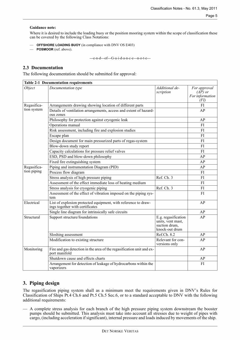
2.3 DocumentationThe following documentation should be submitted for approval:
3. Piping designThe regasification piping system shall as a minimum meet the requirements given in DNV’s Rules forClassification of Ships Pt.4 Ch.6 and Pt.5 Ch.5 Sec.6, or to a standard acceptable to DNV with the followingadditional requirements:
— A complete stress analysis for each branch of the high pressure piping system downstream the boosterpumps should be submitted. This analysis must take into account all stresses due to weight of pipes withcargo, (including acceleration if significant), internal pressure and loads induced by movements of the ship.
Table 2-1 Documentation requirementsObject Documentation type Additional de-
scriptionFor approval
(AP) orFor information
(FI)Regasifica-tion system
Arrangements drawing showing location of different parts FIDetails of ventilation arrangements, access and extent of hazard-ous zones
AP
Philosophy for protection against cryogenic leak APOperations manual FIRisk assessment, including fire and explosion studies FIEscape plan FIDesign document for main pressurized parts of regas-system FIBlow-down study report FICapacity calculations for pressure relief valves FIESD, PSD and blow-down philosophy APFixed fire extinguishing system AP
Regasifica-tion piping
Piping and instrumentation Diagram (PID) APProcess flow diagram FIStress analysis of high pressure piping Ref. Ch. 3 FIAssessment of the effect immediate loss of heating medium FIStress analysis for cryogenic piping Ref. Ch. 3 FIAssessment of the effect of vibration imposed on the piping sys-tem
FI
Electrical List of explosion protected equipment, with reference to draw-ings together with certificates
AP
Single line diagram for intrinsically safe circuits APStructural Support structure/foundations E.g. regasification
units, vent mast, suction drum, knock-out drum
AP
Sloshing assessment Ref.Ch. 8.2 APModification to existing structure Relevant for con-
versions onlyAP
Monitoring Fire and gas detection in the area of the regasification unit and ex-port manifold
AP
Shutdown cause and effects charts APArrangement for detection of leakage of hydrocarbons within the vaporizers
FI
DET NORSKE VERITAS
Classification Notes - No. 61.3, May 2011
Page 6
— Stress analysis for piping with temperature below -110ºC taking into account thermal contraction shouldalso be performed and submitted for information.
— The above calculations should be carried out according to a recognized code or practice (i.e. ASME B31.3).— The effect of vibrations imposed on the piping system in the regasification plant should be evaluated when
vibrations excited by thrusters or other relevant excitation sources may be expected. Suitablecountermeasures shall be implemented.
— Expansion bellows should not be used in the high pressure piping system.
4. Materials, Manufacture, Inspection and Testing
4.1 MaterialsMaterials for the liquefied gas piping and cargo vapour piping shall be suitable for low temperature service. Ingeneral material should be selected for a temperature of –165°C.
Requirements for materials, documentation and testing, related to gas service see DNV’s Rules forClassification of Ships Pt.5 Ch.5 Sec.2 D (Table D4) and E (Table E1). For steam service see DNV’s Rules forClassification of Ships Pt.4 Ch.6 Sec.2 Table A2.
4.2 Piping design and manufactureCargo- and process piping shall be joined by butt welding. The number of flanges is to be kept to a minimum.
Valves and expansion bellows should preferably be of weld-in type.
For requirements to design, welding and testing, reference is made to DNV’s Rules for Classification of ShipsPt.5 Ch.5 Sec.6 C500-C800.
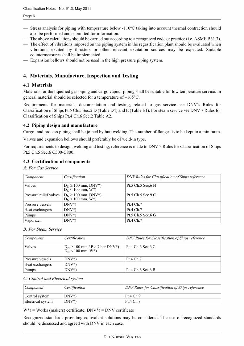
4.3 Certification of componentsA: For Gas Service
B: For Steam Service
C: Control and Electrical system
W*) = Works (makers) certificate; DNV*) = DNV certificate
Recognized standards providing equivalent solutions may be considered. The use of recognized standardsshould be discussed and agreed with DNV in each case.
Component Certification DNV Rules for Classification of Ships reference
Valves DN 100 mm, DNV*)DN < 100 mm, W*)
Pt.5 Ch.5 Sec.6 H
Pressure relief valves DN 100 mm, DNV*)DN < 100 mm, W*)
Pt.5 Ch.5 Sec.9 C
Pressure vessels DNV*) Pt.4 Ch.7Heat exchangers DNV*) Pt.4 Ch.7Pumps DNV*) Pt.5 Ch.5 Sec.6 GVaporizer DNV*) Pt.4 Ch.7
Component Certification DNV Rules for Classification of Ships reference
Valves DN 100 mm / P > 7 bar DNV*)DN < 100 mm, W*)
Pt.4 Ch.6 Sec.6 C
Pressure vessels DNV*) Pt.4 Ch.7Heat exchangers DNV*)Pumps DNV*) Pt.4 Ch.6 Sec.6 B
Component Certification DNV Rules for Classification of Ships reference
Control system DNV*) Pt.4 Ch.9Electrical system DNV*) Pt.4 Ch.8
DET NORSKE VERITAS
Classification Notes - No. 61.3, May 2011
Page 7
4.4 Strength and tightness testingCargo- and process piping shall be hydrostatically tested to 1.5 times the design pressure prior to installation.Heat exchangers are to be tested to 1.3 times the design pressure. Testing by using gas instead of liquid may beaccepted on special considerations of safety implications.
Other piping may either be hydrostatically tested prior to- or after installation onboard.
After assembly onboard the complete cargo piping shall be subjected to a leak test using air, halides or othersuitable medium according to an approved procedure.
5. General Safety
5.1 Risk assessmentA risk assessment should be conducted, preferably in the early phase of the project, and should include at leastassessment of the following:
— collision— fire- and explosion— dropped object— cryogenic leakage.
The findings from the risk assessments carried out are to be considered in the design phase and addressed inthe documentation submitted to class. The risk assessment should comply with the principles outlined in DNV-OS-A101 App. C.
Design loads and recommendations from the risk assessment are to be addressed in the final design.
5.2 Classification and extent of Hazardous area For deciding the extent of the hazardous area of a non-standard application on a gas carrier, the followingshould be considered:
— Regulations under the provisions of the IEC regime, with basis in IEC 60092-502, also referred to in IGCcode through IMO resolution MSC.177(79): “Adoption of Amendments to the international code on the
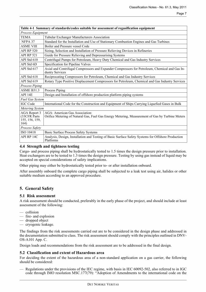
Table 4-1 Summary of standards/codes suitable for assessment of regasification equipment Process EquipmentTEMA Tubular Exchanger Manufacturers Association NFPA 37 Standard for the Installation and Use of Stationary Combustion Engines and Gas TurbinesASME VIII Boiler and Pressure vessel CodeAPI RP 520 Sizing, Selection and Installation of Pressure Relieving Devices in RefineriesAPI RP 521 Guide for Pressure Relieving and Depressurising SystemsAPI Std 610 Centrifugal Pumps for Petroleum, Heavy Duty Chemical and Gas Industry ServicesAPI Std 6D Specification for Pipeline ValvesAPI Std 617 Axial and Centrifugal Compressors and Expander Compressors for Petroleum, Chemical and Gas In-
dustry ServicesAPI Std 618 Reciprocating Compressors for Petroleum, Chemical and Gas Industry ServicesAPI Std 619 Rotary Type Positive Displacement Compressors for Petroleum, Chemical and Gas Industry ServicesProcess PipingASME B31.3 Process PipingAPI 14E Design and Installation of offshore production platform piping systemsFuel Gas SystemIGC Code International Code for the Construction and Equipment of Ships Carrying Liquefied Gases in BulkMetering SystemAGA Report 3(33CFR Parts 155, 156, 159, 164)
AGA: American Gas Association: Orifice Metering of Natural Gas, Fuel Gas Energy Metering, Measurement of Gas by Turbine Meters
Process SafetyISO 10418 Basic Surface Process Safety SystemsAPI RP 14C Analysis, Design, Installation and Testing of Basic Surface Safety Systems for Offshore Production
Platforms
DET NORSKE VERITAS

Classification Notes - No. 61.3, May 2011
Page 8
Construction and Equipment of Ships carrying liquefied gases in bulk (IGC code)”. Adopted on 10December 2004.
— The IEC standard 60092-502 covering most typical arrangements on a gas carrier. The principles of thestandard are implemented in DNV’s Rules for Classification of Ships.
It is recommended that area classification is undertaken in such a way that the various steps which lead to thefinal area classification are properly documented.
All relevant information used should be referred to. Examples of such information or method used, would be:
a) Recommendations from relevant codes and standards.
b) Gas and vapour dispersion characteristics and calculations.
c) A study of ventilation characteristics in relation to flammable material release parameters so that theeffectiveness of the ventilation can be evaluated.
It should be noted that the above approach refers to equipment and solutions/applications not consideredcovered directly by the prescriptive solutions found in the IGC Code or IEC 60092-502.
5.3 Cryogenic Releases
5.3.1 Protection of deckIt shall be documented that the deck is protected from cryogenic spill at the regasification unit and suctiondrum, alternatively that the deck is suitable for cryogenic temperatures.
5.3.2 Spray shieldsFor high pressure liquid lines downstream booster pumps, spray shields shall be provided for any flangedconnections, to protect personnel and prevent deck and cargo tanks from being exposed to high pressure LNG.
5.4 Fire Safety
5.4.1 Water spray systemA water-spray system with an application rate of 10 l/m2/min. of the horizontally projected area of theregasification system shall be arranged to protect:
— the regasification units — metering station — suction drum— export manifold— internal surfaces of the turret compartment— storage tanks for propane or other flammable fluids, if fitted.
The arrangements and capacities of the water spray pumps shall be such that with one spray pump system outof operation the remaining pump system shall have capacity to supply the spray system as well as the fire mainif combined pumps are used.
Guidance note:Firewater to the water spray system is to be available after any design accidental event. For example fire in one areashould not result in complete loss of fire fighting capability. Fire fighting capability should also be maintained wherean accidental event results in loss of main power.
---e-n-d---of---G-u-i-d-a-n-c-e---n-o-t-e---
5.4.2 Dry chemical powderThe regasification plant shall be covered by a dry chemical powder fire-extinguishing system complying withthe requirements in DNV’s Rules for Classification of Ships Pt.5 Ch.5 Sec.11.
5.4.3 Fire detectionA suitable number of fire detectors including flame detectors, shall be fitted to cover the regasification unitsand export manifold.
5.5 Physical protection of regasification unitsDepending on operational conditions the regasification units should be placed in a sheltered location protectedfrom green seas.
DET NORSKE VERITAS
Classification Notes - No. 61.3, May 2011
Page 9
5.6 Gas detection
5.6.1 The regasification plant is to be equipped with a sufficient number of gas detectors of the continuousmonitoring type covering:
— regasification units — ventilation inlets to accommodation and engine room— condensate return to engine room (other systems not physically segregated from the gas system)— export manifold— turret compartment.
5.6.2 Audible and visual alarms from the gas detection equipment to be located on the navigating bridge, in thecontrol position for cargo operation, and at the gas detector readout location.
5.7 Heating system for LNG vaporisers
5.7.1 Heating may be arranged as direct heating or indirect heating, i.e. an intermediate heating circuit. See chapter11 for examples of heating arrangements.
5.7.2 Means shall be provided to detect leakage of high pressure LNG/NG into the heating fluid, to preventoverpressure in the heating system and to protect the vaporizers against freezing of heating medium.
5.8 Escape
5.8.1 Passages for safe escape from areas of the regasification unit, the export manifold and loading manifold (in caseship-to-ship transfer is intended) shall be arranged. Shielding from fire and heat radiation shall be provided foras necessary.
5.8.2 Two escape ways from normally manned areas shall be arranged.
6. Process Safety
6.1 GeneralThe regasification plant is to be designed so that a single accidental event shall not result in a critical situation.
Guidance note:The safety system is to provide two levels of protection to prevent or minimise the effects of an equipment failurewithin the regasification plant. These means of protection are to be independent of each other and in addition to thecontrol devices used in normal operation. Reference is made to the safety design philosophy in API RP 14C.
---e-n-d---of---G-u-i-d-a-n-c-e---n-o-t-e---
6.2 Process Shut-Down System (PSD)
6.2.1 A Process Shut-Down System (PSD) for the regasification system shall be arranged. Initiation of PSD shall befrom the monitoring system as indicated in Table 6-1, from manual call points and from fire detectors in theregasification area.
6.2.2 Activation of the PSD shall stop the LNG booster pump for the relevant regasification unit.
6.3 ESDIn context of this Classification Note the ESD system is the emergency shut down facility for the cargohandling system required by the IGC Code.
Activation of the ESD will:
— stop cargo pumps, spray pumps and booster pumps
DET NORSKE VERITAS
Classification Notes - No. 61.3, May 2011
Page 10
— close all valves on the tank dome, in the case of cargo tanks with pressure relief valves set at a pressureabove 0.7 barg
— close the cargo manifold/turret valves.
The ESD system is activated by manual call points and by fusible elements / fire detectors located in way ofthe cargo manifold, cargo tank domes and regasification units.
6.4 Blow down system
6.4.1 A blow down system shall be provided for the regasification plant.
Guidance note:The blow down system shall be arranged to vent all parts of the regasification system containing more than 400 kg offlammable inventory to the vent system.
---e-n-d---of---G-u-i-d-a-n-c-e---n-o-t-e---
6.4.2 Activation of the blow down system shall be by:
— manual call points located in the cargo control room, in the area of the regasification units and exportmanifold and the navigation bridge
— automatic by the fire detectors in the regasification area based on voting.
6.5 Pressure relief
6.5.1 If a suction drum in the inlet to the high pressure booster pump is fitted, it shall be provided with a relief valvesized for relevant cases i.e. fire exposure and blocked booster pump outlet.
6.5.2 Pressure relief valves shall be fitted in sections of the piping system where liquid can be trapped. Reference isalso made to DNV’s Rules for Classification of Ships Pt.5 Ch.5 Sec.6.
The relief valves should discharge into the cargo tanks or to vent mast if means are provided to detect anddispose of any liquid cargo which may flow into the vent system.
In case of relief to cargo tanks, the effect of routing high pressure LNG/NG to the cargo tank must bedocumented.
6.6 Vent system
6.6.1 Special consideration needs to be given with respect to release rate and the potential for liquid flow through thevent mast. Part of the regasification plant will contain high pressure LNG and part will contain high pressuregas. Relief arrangements for both phases will need to be considered.
6.6.2 In general, the fitting of a knock-out drum to be considered between the relief valves and the vent mast. Theknock out drum shall be provided with high level alarm.
As an alternative, a calculation showing sufficient capacity of the vent mast to avoid any liquid release throughthe mast is to be carried out.
For permanently moored vessels it may be considered disposing of gas via a flare rather than a vent. In suchcases the capacity should be assessed per API RP 521 and it should be ensured that radiation levels are withinacceptable limits.
6.7 Monitoring systemsMonitoring systems should in general comply with the requirements of the DNV’s Rules for Classification ofShips Pt.4 Ch.9.
Furthermore, it is assumed that the regasification process is under constant surveillance and control by qualifiedpersonnel.
The table below gives an overview of a typical extent of monitoring and control of regasification systems. Thisshould be considered guidance and the requirements to monitoring and control will be subject to special
DET NORSKE VERITAS
Classification Notes - No. 61.3, May 2011
Page 11
consideration on a case by case basis.
Separate transmitters to be provided for control and shutdown functions.
The control and safety system must be designed to ensure that no single failure leads to a dangerous situation.If a PSD (Process shut down) input signal is lost, the corresponding shutdown must be activated immediately.However, if instrument redundancy is provided, with two or more dedicated shut down transmitters (for theinput), it is acceptable to continue with one healthy transmitter. In that case any failure state on the remainingtransmitter/signal must activate a shutdown. Also note that if two transmitters are used, shutdown is to beactivated if signal from one of the transmitters reaches the limit for activation.
7. Functional requirements
7.1 Start-up procedureThe system must be designed with planned operational procedures to prevent excessive temperaturedifferential. In case a suction drum is installed, it should be verified that the procedure for filling the suctiondrum for temporary containment of LNG from the cargo tanks is acceptable with respect to temperaturedifferential. A pressure relief valve (PSV) on suction drum and a pressure control system to vapour main to beprovided, preventing excess vapour generation if LNG enters a warm suction drum.
It must be ensured that valves and instrumentation allow appropriate pump cool down procedure in order toavoid excess temperature differential and possible pump damage with subsequent release of LNG.
Position indication should be provided on pump suction manual valve(s), interlocked to prevent pumpoperation if closed.
7.2 Operational An operations manual should be provided, including start and stop procedures, safety precautions, andemergency procedures.
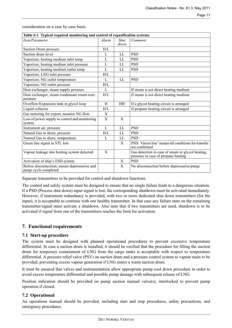
Table 6-1 Typical required monitoring and control of regasification systems Item/Parameter Alarm Shut
downComment
Suction Drum pressure H/LSuction drum level L LL PSDVaporizer, heating medium inlet temp L LL PSDVaporizer, heating medium inlet pressure L LL PSDVaporizer, heating medium outlet temp L LL PSDVaporizer, LNG inlet pressure H/LVaporizer, NG outlet temperature L LL PSD Vaporizer, NG outlet pressure H/LHeat exchanger, steam supply pressure L If steam is not direct heating mediumHeat exchanger, steam condensate return tem-perature
H/L If steam is not direct heating medium
Overflow/Expansion tank in glycol loop H HH If a glycol heating circuit is arrangedLiquid collector H/L If propane heating circuit is arrangedGas metering for export, monitor NG flow XLoss of power supply to control and monitoring system
X X
Instrument air, pressure L LL PSDNatural Gas to shore, pressure H/L LL PSD Natural Gas to shore, temperature L LL PSD Green line signal in STL lost X PSD. ’Green line’ means all conditions for transfer
are confirmed Vapour leakage into heating system detected X Gas detection in case of steam or glycol heating,
pressure in case of propane heatingActivation of ship’s ESD system X PSDBefore disconnection; ensure depressurize and purge cycle completed
X No disconnection before depressurize/purge
DET NORSKE VERITAS

Classification Notes - No. 61.3, May 2011
Page 12
7.3 Survey requirements for the in-service phaseThe installations and equipment related to the regasification system is subject to survey in service according tothe requirements for cargo handling equipment for gas carriers. Reference is made to DNV’s Rules forClassification of Ships Pt.7 Ch.1 Sec.2 C.
For permanently moored regasification vessels special tailor-made survey programmes may be agreed upon.
8. Implications on Ship DesignThe gas carrier design may be affected by continuous and even limited regasification operation and processingand export of high pressure gas. This might also affect areas and issues outside of the area of which theregasification unit is located.
8.1 Environmental conditionsA vessel intended to operate in all sea areas should be designed, with regard to structural strength, for theenvironmental loading in the North Atlantic conditions with a return period of 20 years.
For vessels located continuously at one location design should consider environmental conditions for a 100years return period at the specific site.
For fatigue the basic requirement is 20 years design life based on a scatter diagram for world wide operationor at designated operation site as applicable.
8.2 SloshingOperating a vessel as a regasification vessel will involve load cases where the cargo tanks will haveintermediate filling levels during the period of unloading. An assessment of the sloshing capabilities of thecargo containment system must therefore be carried out and documented as relevant. Also the capacity of thehull is to be evaluated for these increased loads. The degree of documentation required will depend on the cargocontainment system. For assessment on membrane cargo tanks reference is made to DNV Classification NoteNo.30.9.
For a ship with a membrane or spherical cargo containment system the sloshing assessment should include:
— pump tower— pump tower supports.
at all filling levels during operation.
For a ship with membrane tanks the sloshing assessment is also to include:
— cargo tank.
For a ship with prismatic cargo tanks the sloshing assessment is to include:
— cargo tank — pump and piping connections to the internal tank structure.
8.3 Structural support of regasification equipment on deckInteraction between the equipment for regasification and the hull to be considered in the design.
8.4 Gas detection in air inlets to the accommodationIt should be considered what the likelihood of gas reaching the accommodation will be, and what measuresshould be in place to protect against gas ingress. This might involve location of detectors in the ventilation inletsystem to the accommodation with subsequent manual or automatic action on detection of gas.
8.5 Ship to ship transferFor regasification vessels receiving LNG via ship-to-ship transfer, arrangements for emergency disconnectionof loading arms or loading hoses and quick release of moorings should be considered taking into accountlocation and weather conditions
9. Arrangement for submerged turret offloadingThe design of submerged turret offloading system is to be in compliance with DNV’s Rules for Classificationof Ships Pt.5 Ch.3 Sec.14. In addition, the following apply for Submerged Turret Loading system (STL)intended for export of high pressure natural gas:
DET NORSKE VERITAS

Classification Notes - No. 61.3, May 2011
Page 13
— Explosion design loads due to explosion overpressure to be quantified and specifically designed for withrespect to STL trunk and explosion relief arrangement.
— The STL room to be fitted with two independent means of escape.— It must be ensured that positive isolation of regasification from STL can be provided, as well as positive
isolation of regasification from the pump in the cargo tank. The isolation valves to STL to be remotelyoperable and fitted with position monitoring, which interfaces with STL depressurization and purging cyclemonitoring.
— It must be ensured that PSD is immediately activated if green line signal in STL is lost.— In case of differential pressure between sub-sea pipeline and regasification export pipe, it should be ensured
that pipeline and buoy valves cannot be opened until the pressure difference is equalized. — It must be ensured that the pipeline and regasification system will shutdown upon positive confirmation of
gas detected in the turret compartment.— Prior to disconnecting the STL piping must be depressurized and purged. Depressurization and purge cycle
to be completed and confirmed, as part of the STL logic before next step can be initiated.— Buoy and subsea valves should be fitted with proximity switches or similar for positive confirmation of
connection/disconnection.
10. Testing and Commissioning
10.1 Alarms and safety functions All alarms and safety functions are to be tested, including gas detection system.
10.2 Fire alarms, fire extinction systems and water spray systemsFire alarms, fire extinction systems and water spray systems are to be tested.
10.3 Equipment and automatic control systemsAt the first cargo regasification offloading operation, a surveyor shall witness the operations for verification ofsatisfactory function of equipment and automatic control systems.
11. Examples of heating arrangements for LNG vaporisers
11.1 Closed loop with steam heating
Figure 11-1LNG is directly heated by steam
Booster
Production pump
Suction drum
Steam in Condensate
NG out
LNG
DET NORSKE VERITAS

Classification Notes - No. 61.3, May 2011
Page 14
11.2 Combined open/closed loop with seawater and steam heating
Figure 11-2LNG is directly heated by seawater. At low sea water temperatures the seawater is preheated in a steamheater.
11.3 Open loop with seawater heating and intermediate propane loop
Figure 11-3LNG is heated against an intermediate loop with propane and against seawater
Booster
Production pump
Suction drum
Steam in Condensate
NG out
Seawater
Seawater
LNG
Booster
Production pump
Suction drum
NG out
Seawater
Seawater Propane system LNG
DET NORSKE VERITAS
Classification Notes - No. 61.3, May 2011
Page 15
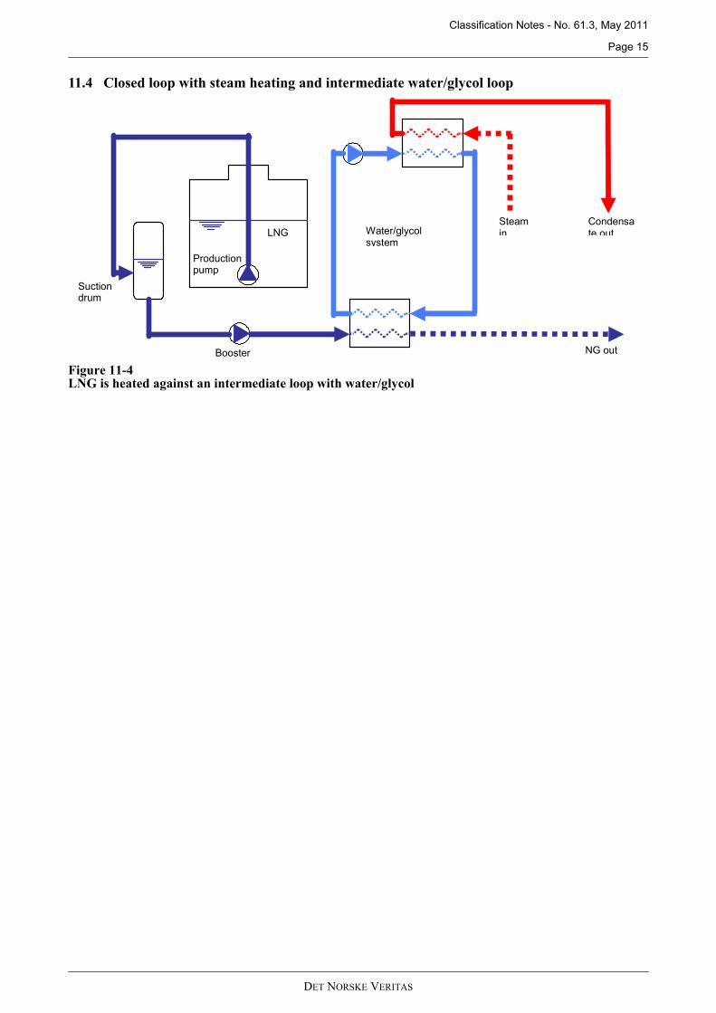
11.4 Closed loop with steam heating and intermediate water/glycol loop
Figure 11-4LNG is heated against an intermediate loop with water/glycol
Booster
Production pump
Suction drum
Steam in
Condensate out
NG out
Water/glycol system
LNG
DET NORSKE VERITAS