Direct Metal Laser Sintering R1
25
Direct Metal Laser Sintering: An Overview Peter Cerreta E.I.T The University of North Florida EML 6933 Advanced Materials and Processes Department Of Mechanical Engineering Fall 2014
-
Upload
peter-cerreta -
Category
Documents
-
view
139 -
download
1
Transcript of Direct Metal Laser Sintering R1
Direct Metal Laser Sintering: An Overview
Peter Cerreta E.I.T
The University of North Florida
EML 6933 Advanced Materials and Processes
Department Of Mechanical Engineering
Fall 2014

University Of North Florida
Fall 2014
2
Table of Contents 1 Introduction ........................................................................................................................................... 3
2 History................................................................................................................................................... 3
3 Definitions ............................................................................................................................................. 4
4 Mechanics ............................................................................................................................................. 4
4.1 Binding Mechanisms .................................................................................................................... 4
4.2 Parameters and Densification........................................................................................................ 5
4.3 Process Steps ................................................................................................................................. 5
4.4 Equipment ..................................................................................................................................... 6
4.4.1 Lasers .................................................................................................................................... 6
5 Research Areas ...................................................................................................................................... 6
5.1 Top Surface Quality ...................................................................................................................... 6
5.2 Consolidation Characteristics ....................................................................................................... 6
5.3 Post Processing DMLS Parts ........................................................................................................ 7
6 Applications .......................................................................................................................................... 7
7 Current Barriers and Future Research Areas ........................................................................................ 7
8 Conclusions ........................................................................................................................................... 8

University Of North Florida
Fall 2014
3
1 Introduction
Additive manufacturing (AM) is defined by the American Society of Testing and Materials (ASTM)
as “the process of joining materials to make objects from 3D model data, usually layer upon layer, as
opposed to subtractive manufacturing, methodologies, such as traditional machining”1. AM methods
differ from subtractive methods, such as milling or turning, by the intuitive concept that the part is being
created by the incremental addition of material rather than the incremental subtraction of material1.
Common industry names for the AM methods are: freeform fabrication, additive processes, layered
manufacturing (LM), additive techniques, and additive layer manufacturing (ALM)1. Currently, there are
seven ALM processes with the following normalized names adopted by ASTM International Committee
F42 on Additive Manufacturing Technologies: Vat Photopolymerization process (commercially known as
steriolithography), Material Jetting (ink jet printing), Binder Jetting (3d printing), Material Extrusion
(fused deposition modeling), Sheet Lamination (laminated object manufacturing), Direct Energy
Deposition (laser engineered net shaping), and Powder Bed Fusion [selective laser sintering (SLS),
selective laser melting (SLM) , electron beam melting (EBM), direct metal manufacturing, and direct
metal laser sintering (DMLS)]1.
Over the last several years, many authors have formed publications aimed at providing an overview
of additive manufacturing technologies2, their respective histories
3,4, and, more recently, a framework for
their implementation5. Levy provided an excellent summary of LM technologies, their acronyms, and
their corresponding development years (Table 1, Appendix A)2. In addition, Levy distinguished rapid
manufacturing from rapid tooling (Figure 1, Appendix A), and also direct technologies from indirect
technologies (Table 2, Appendix A). Bourell provided an “Early Chronology of Additive Processes”and
was able to identify the earliest roots of AM technologies from a review of US patent literature3 (Figure 2,
Appendix A), while Shellabear gave “Development History and State of the Art” of DMLS 4. In 2013,
Mellor proposed a framework of AM implementation that consisted of AM: strategy, supply chain,
systems of operations, organizational change, and technologies (Figure 3, Appendix A)5.
The aim of this work is to provide the reader with an understanding of Direct Metal Laser Sintering
(DMLS), a specific AM method, by surveying the current literature available on the subject. As
mentioned earlier, DMLS would fall under the ASTM standardized name of Powder Bed Fusion. DMLS
involves selectively applying energy to a powder bed of metal particles via a laser beam as a means of
sintering them together in a layer-by-layer fashion, resulting in a solid part2. Mellor provided a very
extensive list of benefits associated with DMLS such as the ability to produce parts with complex
geometry, save time for creating functional prototypes, and reduce material waste associated with making
parts5.
2 History
According to Bourell, all AM methods can be traced back to two early roots, specifically the
topographical and photosculpture methods3. Blanther developed the topographical method in 1890 as a
means to create a mold for topographical relief maps (Figure 4, Appendix A) 3. The photosculpture
University Of North Florida
Fall 2014
4
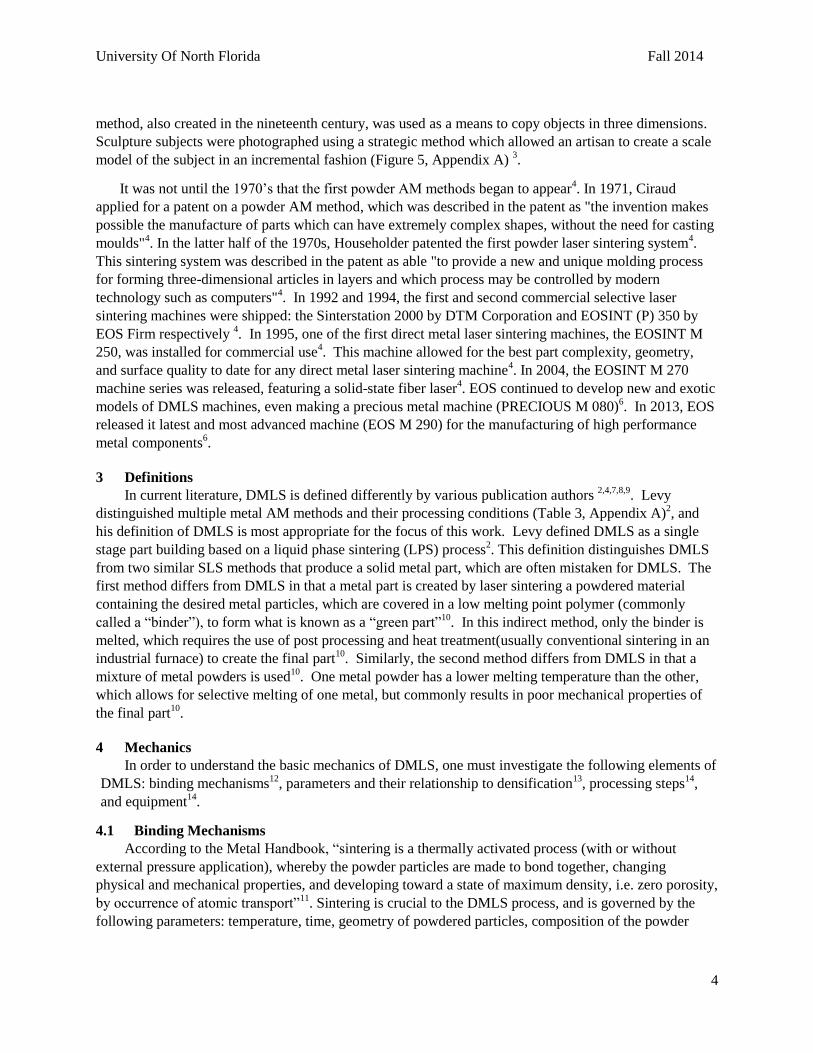
method, also created in the nineteenth century, was used as a means to copy objects in three dimensions.
Sculpture subjects were photographed using a strategic method which allowed an artisan to create a scale
model of the subject in an incremental fashion (Figure 5, Appendix A) 3.
It was not until the 1970’s that the first powder AM methods began to appear4. In 1971, Ciraud
applied for a patent on a powder AM method, which was described in the patent as "the invention makes
possible the manufacture of parts which can have extremely complex shapes, without the need for casting
moulds"4. In the latter half of the 1970s, Householder patented the first powder laser sintering system
4.
This sintering system was described in the patent as able "to provide a new and unique molding process
for forming three-dimensional articles in layers and which process may be controlled by modern
technology such as computers"4. In 1992 and 1994, the first and second commercial selective laser
sintering machines were shipped: the Sinterstation 2000 by DTM Corporation and EOSINT (P) 350 by
EOS Firm respectively 4. In 1995, one of the first direct metal laser sintering machines, the EOSINT M
250, was installed for commercial use4. This machine allowed for the best part complexity, geometry,
and surface quality to date for any direct metal laser sintering machine4. In 2004, the EOSINT M 270
machine series was released, featuring a solid-state fiber laser4. EOS continued to develop new and exotic
models of DMLS machines, even making a precious metal machine (PRECIOUS M 080)6. In 2013, EOS
released it latest and most advanced machine (EOS M 290) for the manufacturing of high performance
metal components6.
3 Definitions
In current literature, DMLS is defined differently by various publication authors 2,4,7,8,9
. Levy
distinguished multiple metal AM methods and their processing conditions (Table 3, Appendix A)2, and
his definition of DMLS is most appropriate for the focus of this work. Levy defined DMLS as a single
stage part building based on a liquid phase sintering (LPS) process2. This definition distinguishes DMLS
from two similar SLS methods that produce a solid metal part, which are often mistaken for DMLS. The
first method differs from DMLS in that a metal part is created by laser sintering a powdered material
containing the desired metal particles, which are covered in a low melting point polymer (commonly
called a “binder”), to form what is known as a “green part”10
. In this indirect method, only the binder is
melted, which requires the use of post processing and heat treatment(usually conventional sintering in an
industrial furnace) to create the final part10
. Similarly, the second method differs from DMLS in that a
mixture of metal powders is used10
. One metal powder has a lower melting temperature than the other,
which allows for selective melting of one metal, but commonly results in poor mechanical properties of
the final part10
.
4 Mechanics
In order to understand the basic mechanics of DMLS, one must investigate the following elements of
DMLS: binding mechanisms12
, parameters and their relationship to densification13
, processing steps14
,
and equipment14
.
4.1 Binding Mechanisms
According to the Metal Handbook, “sintering is a thermally activated process (with or without
external pressure application), whereby the powder particles are made to bond together, changing
physical and mechanical properties, and developing toward a state of maximum density, i.e. zero porosity,
by occurrence of atomic transport”11
. Sintering is crucial to the DMLS process, and is governed by the
following parameters: temperature, time, geometry of powdered particles, composition of the powder

University Of North Florida
Fall 2014
5
mix, density of the powder compact, and composition of the protective atmosphere in the sintering
furnace11
.
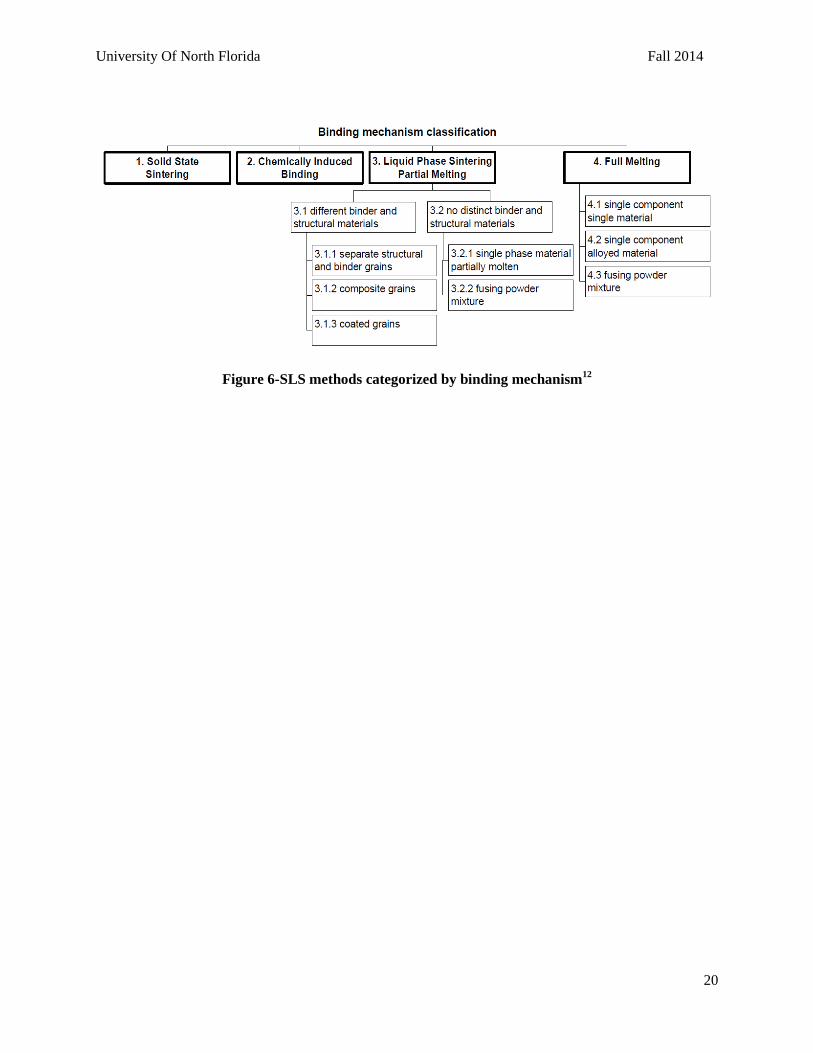
Kruth found that SLS technologies can be categorized by four binding mechanisms: solid state
sintering, chemically induced binding, liquid phase sintering partial melting, and full melting (Figure 6,
Appendix A) 12
. As mentioned earlier, Levy’s definition of DMLS was chosen for the focus of this study,
and consequently only the LP partial melting binding mechanism will be discussed in detail12
. LPS itself
has “two technologies” distinguished by the type of binder used, namely that with a different binder, and
that with no distinct binder12
. DMLS would be classified under the latter technology as a fusing powder
mixture process12
. Fusing powder mixtures are characterized by multiple phases that are partially
molten12
. The author would encourage the reader to further examine the literature for detailed information
on any of the other binding mechanisms12
.
4.2 Parameters and Densification
Simchi provided a comprehensive study wherein six different metal powders were sintered and
analyzed to better understand the mechanisms of densification and the role of manufacturing
parameters13
.
Process parameters were defined as variables that control the laser sintering process, in contrast to
material parameters, defined as: chemical constitutions and the purity of the material, method of alloying,
and particle characteristics13
. Multiple parameters affect the final part density achieved using DMLS, and
the corresponding microstructural features. Laser power, laser wavelength, laser spot size, laser scan rate,
scan line spacing, powder layer thickness, scanning geometry, working atmosphere, and powder bed
temperature are pertinent process parameters. In contrast, particle size, shape, and distribution are
pertinent material parameters13
.
Process parameters were varied, along with scan strategy and sintering atmosphere, and final part
densities were recorded(see Table 4,Appendix A)13
.The conclusions of the study were highly valuable to
the continued research and improvement of DMLS, and are summarized as follows13
: Improved
densification occurs with increased laser energy input to the powder until a certain saturation point.
Chemistry, shape, and size of metal powder particles affect the densification of DMLS processes.
Nitrogen sintering atmosphere yields less densification than argon sintering atmosphere.
Dewidar found that for high-speed steel, part density increased with laser beam power, and decreased
with increasing scan speed and space14
. This makes sense because all three process parameter affect the
amount of energy (the power density) delivered to the selected region of the powder bed. These results
match further studies, specifically Simchi’s study of densification of iron15
, Tang’s research on copper-
based alloy16
, Kruth’s study of lasers and materials17
, and Alkahari’s study of consolidation characteristics
of ferrous-based metal powder18
. In addition, Tang found that particle shape(which affects the loose
powder density) and binder mix fraction affect the final density of the sintered part18
.
4.3 Process Steps
All DMLS parts start as concepts designed in a Computer Aided Design (CAD) software19
. The
corresponding CAD file is then be exported in a printable form (.STL, .STEP) to the DMLS machine19
.
The DMLS machine then builds each layer as follows19
: The stage containing the metal powder is raised.
The new layer of powder is spread across the old layer of powder via a spreading mechanism. The laser
scans the powder bed to selectively sinter particles according to the current slice instructions dictated by

University Of North Florida
Fall 2014
6
the cad file. The build stage is lowered one layer thickness in preparation for receiving the fresh layer of
powder. This process is repeated until the part is finished.
4.4 Equipment
Though there are multiple DMLS machines on the market, a DMLS machine generally consists of
the following components14
: a laser for selective irradiation of the metal powder, focusing optics for beam
consolidation and maximum intensity of the laser beam, scanning mirrors to direct the beam to the desired
powder bed location, a laser chiller unit for temperature control of the laser components, a motion control
table for adding layers of material to the powder bed, a build cylinder for adding the new powder layer, a
spreader assembly for spreading and leveling the powder layer, an inert gas containment and delivery
system for atmospheric gas control which prevents oxidation of particles, and finally a vacuum assembly
for flushing the build chamber(Figure 7, Appendix A).
4.4.1 Lasers
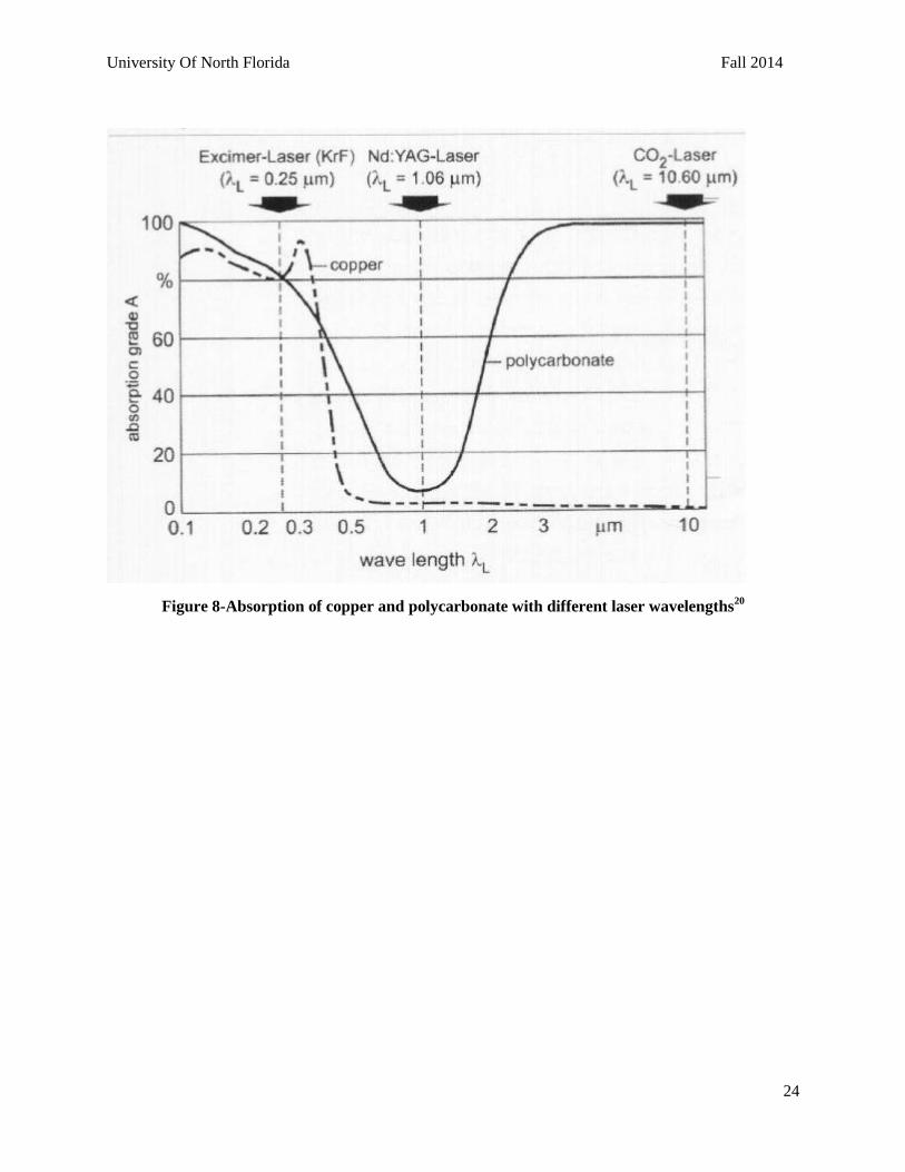
There are mainly four kinds of lasers that are used in DMLS: Solid Fiber Lasers, Carbon Dioxide
(CO2) lasers, Neodymium-Doped Yttrium Aluminium garnet (Nd:YAG) lasers, and disk lasers4 . The
Nd:YAG laser has a wavelength of 1.06µm4,20
. The CO2 laser was the most common laser used in
commercial applications(including DMLS) with a wavelength of 10.6µm; however, it is now being
replaced by fiber and disk lasers, which have shorter wavelengths(less than 2 µm), and allow for faster
build times4. Selection of the laser type and wavelength should be based on the known absorption
characteristics of the material (Figure 8, Appendix A) 20
.
5 Research Areas
Much research has taken place in DMLS since the mid 1990’s, most likely being attributed to the
release of the first commercial SLS machines4. The related works have covered a wide range of subjects
involving DMLS, and can mainly be categorized into five topics: effects of DMLS parameters on
outputs13
, specific DMLS applications and feasibility21,22
, DMLS simulation and modeling23
, investigation
of equipment and process improvements to current DMLS systems18,24
, and DMLS behavior of specific
types of powders10,15,16,25
. For the purpose of this work, certain contemporary investigations have been
considered most beneficial to DMLS theory and have been summarized. These summaries only represent
a small portion of the breadth of works that have occurred in DMLS, and the author would encourage the
reader to delve further into the literature contained in the reference section for more information.
5.1 Top Surface Quality
Yang investigated and defined top surface quality (TSQ) as the surface morphology contained in the
xy plane (the surface parallel to the substrate) 8. TSQ is important because every layer of powder is
sintered on a previously sintered layer of powder, except for the substrate8. If the quality of the bonding
between layers is not high, certain defects can occur such as: balling, warpage, poor densification, and
oxidation8. The study reported that defects could be avoided by maintaining top surface flatness,
compactness, and cleanliness (Table 5, Appendix A) 8. Even further, the TSQ influencing factors were:
surface status of the substrate, additive materials, structural powder morphology, scanning space, layer
thickness, layer number, and balance of laser power and scanning speed8. The results verified that TSQ
heavily influences overall final part qualities, and that its control is paramount for the output of high
performance DMLS parts8.
5.2 Consolidation Characteristics
Another important publication reported on the consolidation characteristics of ferrous-based metal
powder. It utilized a high speed camera with a telescoping lens to record sintering behavior in the powder
University Of North Florida
Fall 2014
7
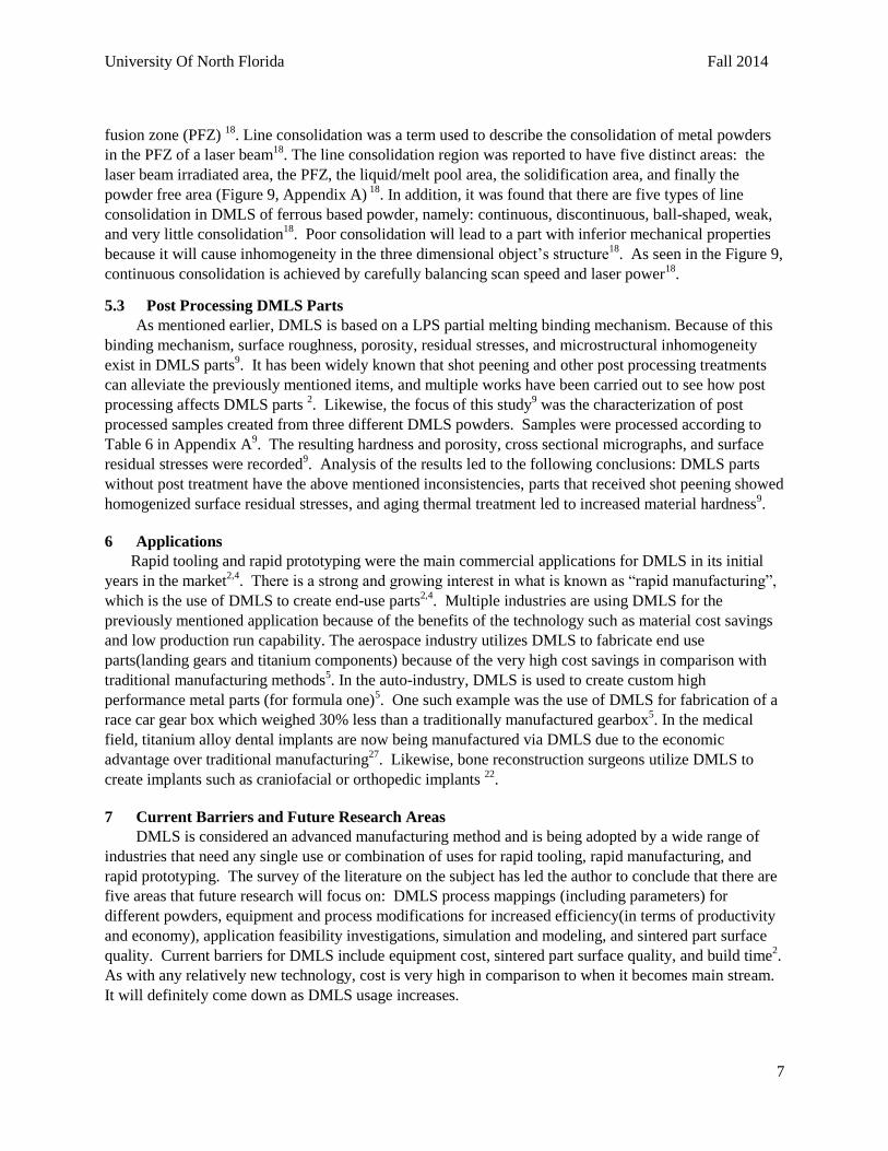
fusion zone (PFZ) 18
. Line consolidation was a term used to describe the consolidation of metal powders
in the PFZ of a laser beam18
. The line consolidation region was reported to have five distinct areas: the
laser beam irradiated area, the PFZ, the liquid/melt pool area, the solidification area, and finally the
powder free area (Figure 9, Appendix A) 18
. In addition, it was found that there are five types of line
consolidation in DMLS of ferrous based powder, namely: continuous, discontinuous, ball-shaped, weak,
and very little consolidation18
. Poor consolidation will lead to a part with inferior mechanical properties
because it will cause inhomogeneity in the three dimensional object’s structure18
. As seen in the Figure 9,
continuous consolidation is achieved by carefully balancing scan speed and laser power18
.
5.3 Post Processing DMLS Parts
As mentioned earlier, DMLS is based on a LPS partial melting binding mechanism. Because of this
binding mechanism, surface roughness, porosity, residual stresses, and microstructural inhomogeneity
exist in DMLS parts9. It has been widely known that shot peening and other post processing treatments
can alleviate the previously mentioned items, and multiple works have been carried out to see how post
processing affects DMLS parts 2. Likewise, the focus of this study
9 was the characterization of post
processed samples created from three different DMLS powders. Samples were processed according to
Table 6 in Appendix A9. The resulting hardness and porosity, cross sectional micrographs, and surface
residual stresses were recorded9. Analysis of the results led to the following conclusions: DMLS parts
without post treatment have the above mentioned inconsistencies, parts that received shot peening showed
homogenized surface residual stresses, and aging thermal treatment led to increased material hardness9.
6 Applications
Rapid tooling and rapid prototyping were the main commercial applications for DMLS in its initial
years in the market2,4
. There is a strong and growing interest in what is known as “rapid manufacturing”,
which is the use of DMLS to create end-use parts2,4
. Multiple industries are using DMLS for the
previously mentioned application because of the benefits of the technology such as material cost savings
and low production run capability. The aerospace industry utilizes DMLS to fabricate end use
parts(landing gears and titanium components) because of the very high cost savings in comparison with
traditional manufacturing methods5. In the auto-industry, DMLS is used to create custom high
performance metal parts (for formula one)5. One such example was the use of DMLS for fabrication of a
race car gear box which weighed 30% less than a traditionally manufactured gearbox5. In the medical
field, titanium alloy dental implants are now being manufactured via DMLS due to the economic
advantage over traditional manufacturing27
. Likewise, bone reconstruction surgeons utilize DMLS to
create implants such as craniofacial or orthopedic implants 22
.
7 Current Barriers and Future Research Areas
DMLS is considered an advanced manufacturing method and is being adopted by a wide range of
industries that need any single use or combination of uses for rapid tooling, rapid manufacturing, and
rapid prototyping. The survey of the literature on the subject has led the author to conclude that there are
five areas that future research will focus on: DMLS process mappings (including parameters) for
different powders, equipment and process modifications for increased efficiency(in terms of productivity
and economy), application feasibility investigations, simulation and modeling, and sintered part surface
quality. Current barriers for DMLS include equipment cost, sintered part surface quality, and build time2.
As with any relatively new technology, cost is very high in comparison to when it becomes main stream.
It will definitely come down as DMLS usage increases.

University Of North Florida
Fall 2014
8
8 Conclusions
It is clear that DMLS has made significant progress since its early roots in the nineteenth century.
The rise of DMLS really followed closely with other AM technologies like steriolithography, fused
deposition modeling, and SLS. AM became the focus of multiple publications in the 1980s thru the
2000s, when various AM technology publications were being released. The publications increased
significantly with the release of the first commercial SLS machines. The past thirty years of publications
tended to focus on the effects of DMLS parameters on outputs, specific DMLS applications and
feasibility, DMLS simulation and modeling, and investigation of equipment and process improvements
to current DMLS systems, and DMLS behavior of specific types of powders.
In surveying the literature, it was found that DMLS process and material parameters strongly
influence part densification. In general, the greater the power density can be delivered to the powder
bed, the better densification the resulting part will have. Power density can be increased by increasing
the laser power, slowing the scan speed, or decreasing the line spacing. Also, smaller particles with
clean surfaces are beneficial to densification in DMLS. In addition, post processing techniques such as
heat treatment, surface polishing, and shot peening improve DMLS part mechanical properties, and can
alleviate inconsistencies that cause inhomogeneity.
Even though the technology is expensive, it is quickly gaining popularity across multiple industries
that are benefiting from it as a rapid manufacturing solution. It is also being used for rapid tooling
solutions to create complicated injection molding tooling that previously couldn’t be created. Businesses
that can afford the technology see a drastic impact to their bottom line in the form of material/labor
savings, or higher margins on sales due to being able to manufacture parts that were once deemed
“impossible”. The future literature on the topic will encompass solutions to current barriers like surface
porosity and build time.

University Of North Florida
Fall 2014
9
References 1. ASTM Standard, Standard Terminology for Additive Manufacturing Technologies, vol. 10.04.
2. Levy GN, Schindel R. MANUFACTURING ( LM ) TECHNOLOGIES , STATE OF THE ART
AND FUTURE. 2(Lm).
3. Bourell DL, Beaman JJ, Leu MC, Rosen DW. A Brief History of Additive Manufacturing and the
2009 Roadmap for Additive Manufacturing : Looking Back and Looking Ahead. 2009.
4. Shellabear M, Nyrhilä O. DMLS – DEVELOPMENT HISTORY AND STATE OF THE ART.
2004.
5. Mellor S, Hao L, Zhang D. Additive manufacturing: A framework for implementation. Int J Prod
Econ. 2014;149:194-201. doi:10.1016/j.ijpe.2013.07.008.
6. Cerreta P. History. Available at http://www.eos.info/about_eos/history.
Accessed December 7, 2014 FL
7. Simchi a., Pohl H. Effects of laser sintering processing parameters on the microstructure and
densification of iron powder. Mater Sci Eng A. 2003;359(1-2):119-128. doi:10.1016/S0921-
5093(03)00341-1.
8. Yang J, Ouyang H, Xu C, Wang Y. Top surface quality research for direct metal laser fabrication.
Rapid Prototyp J. 2012;18(1):4-15. doi:10.1108/13552541211193458.
9. Sanz C, García Navas V. Structural integrity of direct metal laser sintered parts subjected to
thermal and finishing treatments. J Mater Process Technol. 2013;213(12):2126-2136.
doi:10.1016/j.jmatprotec.2013.06.013.
10. Collection PS. Processing conditions and mechanical properties of high-speed steel ... 2003.
11. Metal Hand Book Vol. 7, "Powder Metallurgy," ASM International, Material Park,
Ohio, 1984.
12. Kruth PIJP, Mercelis IP, Froyen PIL, Rombouts IM. Binding Mechanisms in Selective Laser
Sintering and Selective Laser Melting. 2004:44-59.
13. Simchi a. Direct laser sintering of metal powders: Mechanism, kinetics and microstructural
features. Mater Sci Eng A. 2006;428(1-2):148-158. doi:10.1016/j.msea.2006.04.117.
14. Direct and Indirect Laser Sintering of Metals. 2002;(May).
15. Simchi A. Effect of C and Cu addition on the densification and microstructure of iron powder in
direct laser sintering process. 2008;62:2840-2843. doi:10.1016/j.matlet.2008.01.113.
16. Tang Y, Loh HT, Wong YS, Fuh JYH, Lu L, Wang X. Direct laser sintering of a copper-based
alloy for creating three-dimensional metal parts. J Mater Process Technol. 2003;140(1-3
SPEC.):368-372. doi:10.1016/S0924-0136(03)00766-0.

University Of North Florida
Fall 2014
10
17. Purtonen T, Kalliosaari A, Salminen A. Monitoring and Adaptive Control of Laser Processes.
Phys Procedia. 2014;56:1218-1231. doi:10.1016/j.phpro.2014.08.038.
18. Alkahari MR, Furumoto T, Ueda T, Hosokawa A. Consolidation characteristics of ferrous-based
metal powder in additive manufacturing. J Adv Mech Des Syst Manuf. 2014;8(1):JAMDSM0009-
JAMDSM0009. doi:10.1299/jamdsm.2014jamdsm0009.
19. Carter LN, Martin C, Withers PJ, Attallah MM. The influence of the laser scan strategy on grain
structure and cracking behaviour in SLM powder-bed fabricated nickel superalloy. J Alloys
Compd. 2014;615:338-347. doi:10.1016/j.jallcom.2014.06.172.
20. Automation A. Lasers and materials in selective laser sintering. 2003.
21. Simchi A, Godlinski D, Avenue A. Direct Laser Sintering of Aluminum Matrix Composites.
22. Bertol LS, Júnior WK, Silva FP Da, Aumund-Kopp C. Medical design: Direct metal laser
sintering of Ti-6Al-4V. Mater Des. 2010;31(8):3982-3988. doi:10.1016/j.matdes.2010.02.050.
23. Xing J, Sun W, Rana RS, Ieee SM. Optik 3D modeling and testing of transient temperature in
selective laser sintering ( SLS ) process. Opt - Int J Light Electron Opt. 2013;124(4):301-304.
doi:10.1016/j.ijleo.2011.11.064.
24. Wiria FE. Selective laser sintering adaptation tools for cost effective fabrication of biomedical
prototypes. 2010;2(April 2009):90-99. doi:10.1108/13552541011025816.
25. Song B, Dong S, Deng S, Liao H, Coddet C. Optics & Laser Technology Microstructure and
tensile properties of iron parts fabricated by selective laser melting. Opt Laser Technol.
2014;56:451-460. doi:10.1016/j.optlastec.2013.09.017.
26. Additive Manufacturing. 2014;(April):2014. doi:10.1016/S0026-0657(14)70084-0.
27. Akova T, Ucar Y, Tukay A, Balkaya MC, Brantley W a. Comparison of the bond strength of
laser-sintered and cast base metal dental alloys to porcelain. Dent Mater. 2008;24(10):1400-1404.
doi:10.1016/j.dental.2008.03.001.

University Of North Florida
Fall 2014
11
Appendix A

University Of North Florida
Fall 2014
12
Table 1-LM technologies and their corresponding development years2

University Of North Florida
Fall 2014
13
Figure 1-Layer manufacturing categories chart2

University Of North Florida
Fall 2014
14
Table 2- Direct versus indirect technologies table for different materials2

University Of North Florida
Fall 2014
15
Figure 2-Timeline showing AM technologies3

University Of North Florida
Fall 2014
16
Figure 3-AM implementation frame work diagram5

University Of North Florida
Fall 2014
17
Figure 4-Blanthers topographical relief method patent3

University Of North Florida
Fall 2014
18
Figure 5-Photosculpture method in process3

University Of North Florida
Fall 2014
19
Table 3-Different metal AM methods and their processing conditions2
University Of North Florida
Fall 2014
20
Figure 6-SLS methods categorized by binding mechanism12

University Of North Florida
Fall 2014
21
Table 4-Densification of metal powders13

University Of North Florida
Fall 2014
22
Figure 7-DMLS equipment layout14

University Of North Florida
Fall 2014
23
Table 5-Surface defects TSQ8
University Of North Florida
Fall 2014
24
Figure 8-Absorption of copper and polycarbonate with different laser wavelengths20

University Of North Florida
Fall 2014
25
Figure 9-Consolidation mapping with sample photos18
Table 6-Sample processing information9