DESIGN GUIDELINES: DIRECT METAL LASER SINTERING (DMLS) · LASER SINTERING? Direct Metal Laser...
6
3D PRINTING & ADVANCED MANUFACTURING STRATASYS DIRECT.COM DESIGN GUIDELINES: DIRECT METAL LASER SINTERING (DMLS)
Transcript of DESIGN GUIDELINES: DIRECT METAL LASER SINTERING (DMLS) · LASER SINTERING? Direct Metal Laser...
3 D P R I N T I N G & A D V A N C E D M A N U F A C T U R I N G
STRATASYSDIRECT.COM
DESIGN GUIDELINES:DIRECT METAL LASER SINTERING (DMLS)
DMLS DESIGN GUIDELINES / 2
WHAT IS DIRECT METAL LASER SINTERING?
Direct Metal Laser Sintering (DMLS) is an additive manufacturing process. Parts are built
using a laser to selectively sinter (heat and fuse) a powdered metal material into layers.
The process begins once a 3D CAD file is mathematically sliced into multiple 2D cross
sections and uploaded into the system. A ceramic blade pushes build material from a
powder supply to create a uniform layer over a build piston platform. The laser scanning
system literally draws the 2D cross section on the surface of the build material, sintering it
into a solid form.
After the first layer is produced, the build piston is lowered and another powder layer is
pushed into place using the ceramic blade, and the laser sinters the second layer. This
process is repeated until the part is complete. Layer-by-layer manufacturing allows for the
direct fabrication of complex parts that would be cost-prohibitive, and often impossible, to
produce through traditional manufacturing processes.
WHAT DEFINES “PRODUCTION PARTS”?
The only difference between a prototype and a production part is that the production
part meets all the characteristics specified by the design, including physical properties,
dimensional tolerances, overall appearance, and cost requirements. A prototype part
often involves compromises in one or more of these areas, particularly in physical
properties.
While the DMLS process can be an effective prototyping tool, recent advancements in
materials and process control have resulted in the fabrication of parts that are suitable for
many production applications.
DESIGN GUIDELINES
DMLS GENERAL TOLERANCESBased on historical results (and application dependent) general tolerances for DMLS parts
are ±0.005 inch for the first inch and ±0.002 inch per inch thereafter (±0.2 percent). The
finish of DMLS parts as built are 350 Ra - μinch.
Note that geometry and part size impact the ability of the process to meet this guideline, and
must be determined on a case-by-case basis. If Stratasys Direct Manufacturing is informed
of critical tolerances at the time of the RFQ submission, they are able to achieve tighter
tolerances through a series of post processing methods they have learned over the years.
DESIGN GUIDELINESParts can be manufactured using DMLS in a variety of metal and alloy materials. Geometries
remain fixed to a base plate during the building process via a support structure and are
separated afterwards by breaking away the supports. It is not possible, however, to build
detached parts, which can be done when making plastic laser sintered parts.
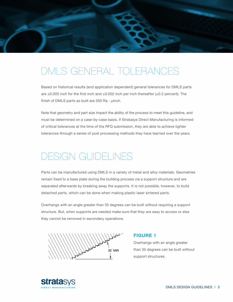
Overhangs with an angle greater than 35 degrees can be built without requiring a support
structure. But, when supports are needed make sure that they are easy to access or else
they cannot be removed in secondary operations.
FIGURE 1
Overhangs with an angle greater
than 35 degrees can be built without
support structures.
DMLS DESIGN GUIDELINES / 3
DESIGN GUIDELINES
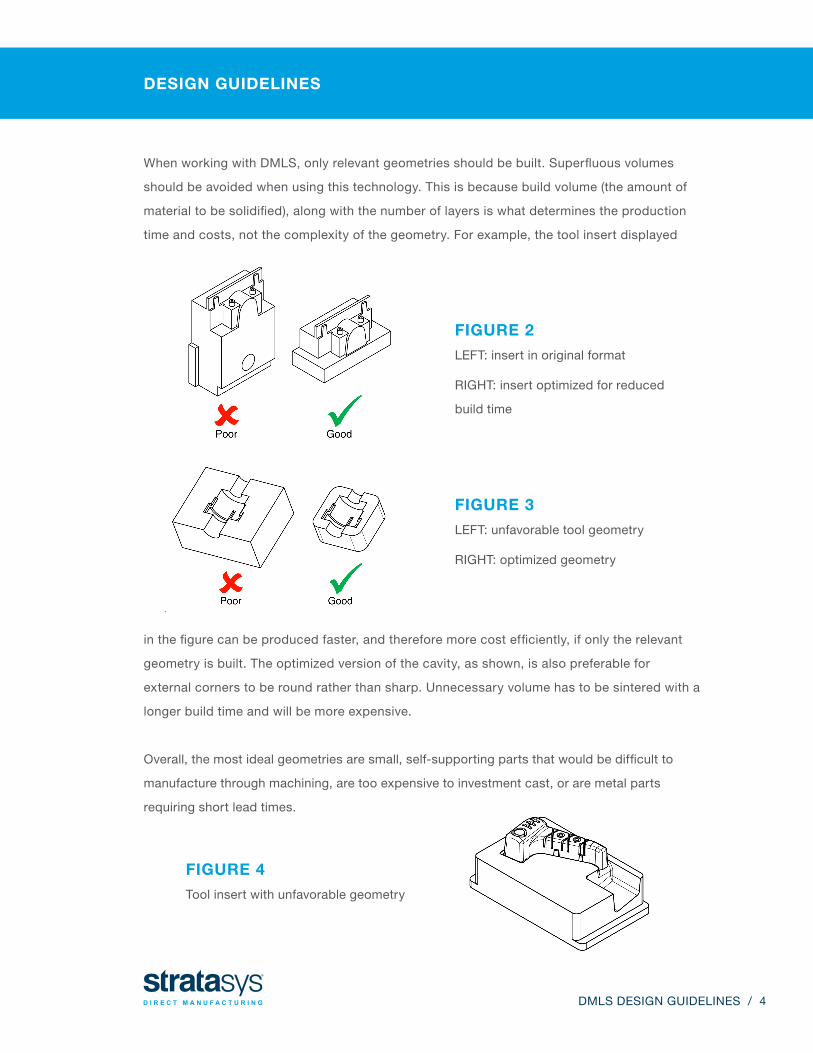
When working with DMLS, only relevant geometries should be built. Superfluous volumes
should be avoided when using this technology. This is because build volume (the amount of
material to be solidified), along with the number of layers is what determines the production
time and costs, not the complexity of the geometry. For example, the tool insert displayed
FIGURE 2
LEFT: insert in original format
RIGHT: insert optimized for reduced
build time
in the figure can be produced faster, and therefore more cost efficiently, if only the relevant
geometry is built. The optimized version of the cavity, as shown, is also preferable for
external corners to be round rather than sharp. Unnecessary volume has to be sintered with a
longer build time and will be more expensive.
Overall, the most ideal geometries are small, self-supporting parts that would be difficult to
manufacture through machining, are too expensive to investment cast, or are metal parts
requiring short lead times.
FIGURE 3
LEFT: unfavorable tool geometry
RIGHT: optimized geometry
FIGURE 4
Tool insert with unfavorable geometry
DMLS DESIGN GUIDELINES / 4
SECONDARY SERVICES FOR FINISHING & POLISHING
HAND FINISHING
DMLS parts may have a raw finish, where surface roughness may be approximately 350 Ra
– μinch or Ra – μmeter 8.75, or a medium turned surface. Our Basic hand finishing service
includes support removal and some layer line and support structure artifact removal.
At minimum, Basic finish is required for all DMLS parts. Our Premium hand finishing service
removes all layer lines, supports and artifacts for a cleaner part. As with any rough surface,
it can be improved up to 1 Ra - μinch or Ra - μmeter 0.025, which qualifies as a super mirror
finish. To achieve the desired surface finish, consider media blasting, tumbling, hand polishing
or secondary operations.
MEDIA BLASTING
Media Blasting is a surface treatment that forcibly propels a high-pressure stream of grit and
ceramic material against the surface of the part to smooth it. First, the part is blasted with an
aluminum oxide abrasive. This mattes the color and smooths the surface. Second, the part is
glass bead blasted. The process provides a satin, matte finish of approximately 98 - 236 μinch
Ra. The finish is largely uniform, but does not provide a 100 percent uniform finish.
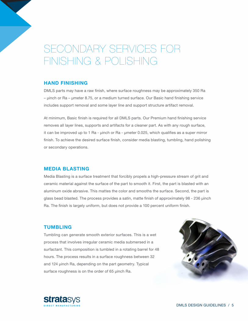
TUMBLING
Tumbling can generate smooth exterior surfaces. This is a wet
process that involves irregular ceramic media submersed in a
surfactant. This composition is tumbled in a rotating barrel for 48
hours. The process results in a surface roughness between 32
and 124 μinch Ra, depending on the part geometry. Typical
surface roughness is on the order of 65 μinch Ra.
DMLS DESIGN GUIDELINES / 5
©2015 Stratasys Direct, Inc. All rights reserved. SD-DG-TEMPLATE-LEGACY-0915
HAND POLISHING
Hand Polishing is performed when projects have geometries in low quantities that are
not tolerance dependent. These polishes are extremely cost effective, and provide a
brilliant, highly-reflective finish.
For this option, engineers must consult with Stratasys Direct Manufacturing prior to
building, because specific surfaces may need to be offset with additional material to
ensure part integrity after post-processing. Note that optical polishing is not the ideal
method for large batches because the finishes can be inconsistent from part to part.
N E E D H E L P S E L E C T I N G T H E B E S T M AT E R I A L & T E C H N O LO GY FO R YO U R PR O J E C T ?
Contact Stratasys Direct Manufacturing Project Engineers for knowledgeable
guidance at 888-311-1017 or at [email protected].
SECONDARY OPERATIONS
• CNC Machining
• Wire EDM
• Welding
• Chemical Etching
• Liquid Honing
• Hot Isostatic Pressing (HIP)
• Heat Treating
• Coating
DMLS parts may require additional finishing for certain applications. Most secondary
operations except for chemical etching and liquid honing require surfaces to be directly
accessible (within line of sight). Our secondary operations include:
STRATASYSDIRECT.COM