
DIL-1, DIL-1/H - M&C Tech Group · The two basic versions DIL-1 and DIL-1/H can be extended by...
29
Gas Dilution Unit DIL-1, DIL-1/H Instruction Manual Version 1.00.01
Transcript of DIL-1, DIL-1/H - M&C Tech Group · The two basic versions DIL-1 and DIL-1/H can be extended by...
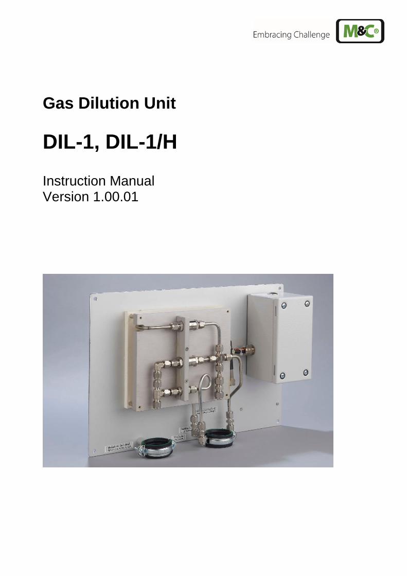
Gas Dilution Unit
DIL-1, DIL-1/H Instruction Manual Version 1.00.01
2 DIL1 | 1.00.01 www.mc-techgroup.com
Dear customer, we have made up this operating manual in such a way that all necessary information about the product can be found and understood quickly and easily. Should you still have any question, please do not hesitate to contact M&C directly or go through your appointed dealer. Respective contact addresses are to be found in the annexe to this operating manual. Please also contact our homepage www.mc-techgroup.com for further information about our products. There, you can read or download the data sheets and operating manuals of all M&C products as well as further information in German, English and French.
This Operating Manual does not claim completeness and may be subject to technical modifications. © 04/2016 M&C TechGroup Germany GmbH. Reproduction of this doc-ument or its content is not allowed without permission from M&C. Version: 1.00.01
www.mc-techgroup.com DIL1 | 1.00.01 3
Contents 1 General information .................................................................................................................... 5 2 declaration of conformity ........................................................................................................... 5 3 Safety instructions...................................................................................................................... 6 4 Warranty ...................................................................................................................................... 6 5 Used terms and signal indications ............................................................................................ 7 6 Introduction ................................................................................................................................. 8 7 Application .................................................................................................................................. 8
7.1 Variations ............................................................................................................................ 10 8 Technical Data .......................................................................................................................... 13 9 Dilution principle ...................................................................................................................... 14 10 Dimensions ............................................................................................................................... 15 11 Receipt and storage .................................................................................................................. 18 12 Installation information ............................................................................................................ 18 13 Installation ................................................................................................................................. 18
13.1 Connection of the supply or sample lines ............................................................................ 18 13.2 Connection of sample gas and heated sample lines ............................................................ 19 13.3 Connection of dilution gas or bypass gas ............................................................................ 20 13.4 Connection of calibration gas............................................................................................... 20 13.5 Electrical connection ............................................................................................................ 20
14 Initial starting ............................................................................................................................ 21 14.1 Calibration ........................................................................................................................... 23
15 Closing down ............................................................................................................................ 24 16 Maintenance .............................................................................................................................. 25
16.1 Disassembly of the crosspiece ............................................................................................ 26 16.2 Cleaning of the critical orifice and check or change of the O-rings ....................................... 27 16.3 Change and cleaning of the injection nozzle ........................................................................ 28 16.4 Removing the bypass T-piece ............................................................................................. 28 16.5 Change and cleaning of the bypass injection nozzle and control or change of the o-ring ..... 28
17 Spare parts list .......................................................................................................................... 29 18 Appendix ................................................................................................................................... 29
4 DIL1 | 1.00.01 www.mc-techgroup.com
List of Illustrations Figure 1 Dilution unit DIL-1 ............................................................................................................ 8 Figure 2 Dilution unit DIL-1/H ......................................................................................................... 9 Figure 3 Gas flow scheme DIL-1 with possible options .................................................................11 Figure 4 Gas flow scheme DIL-1/H with possible options ..............................................................11 Figure 5 Dilution unit DIL-1/H with control panel –S or -S1 ............................................................12 Figure 6 Dilution unit DIL-1/H with set -A or -A1 ............................................................................12 Figure 7 Dilution principle ..............................................................................................................14 Figure 8 Dimensions (mm) dilution units DIL–1.. and control panel –S or –S1 ..............................17 Figure 9 DIL-1 with control panel -S1 ............................................................................................17 Figure 10 Electrical connection for DIL-1/H.. ...................................................................................21 Figure 11 Extract from the injector data sheet .................................................................................23 Figure 12 Suction flow at 0,9 or 1bar abs. in dependence on the bypass gas pressure .................23 Figure 13 Explosion drawing of the dilution crosspiece ...................................................................26 Figure 14 Crosspiece with critical orifice and O-ring seals ..............................................................27 Figure 15 Bypass T-piece with injection nozzle and o-ring ..............................................................28

www.mc-techgroup.com DIL1 | 1.00.01 5
Head Office M&C TechGroup Germany GmbH Rehhecke 79 40885 Ratingen Germany Telephone: 02102 / 935 - 0 Fax: 02102 / 935 - 111 E - mail: [email protected] www.mc-techgroup.com
1 GENERAL INFORMATION
The product described in this operating manual has been examined before delivery and left our works in perfect condition related to safety regulations. In order to keep this condition and to guarantee a safe operation, it is important to heed the notes and prescriptions made in this operating manual. Further-more, attention must be paid to appropriate transportation, correct storage, as well as professional in-stallation and maintenance work. All necessary information a skilled staff will need for appropriate use of this product are given in this operating manual.
2 DECLARATION OF CONFORMITY
CE - Certification The product described in this operating manual complies with the following EU directives: EMV-Instruction The requirements of the EU directive 2014/30/EU “Electromagnetic compatibility“ are met. Low Voltage Directive The requirement of the EU directive 2014/35/EU “Low Voltage Directive“ are met. The compliance with this EU directive has been examined according to DIN EN 61010. Declaration of conformity The EU Declaration of conformity can be downloaded from the M&C homepage or directly requested from M&C.
6 DIL1 | 1.00.01 www.mc-techgroup.com
3 SAFETY INSTRUCTIONS
Please take care of the following basic safety procedures when mounting, starting up or operating this equipment: Read this operating manual before starting up and use of the equipment. The information and warnings given in this operating manual must be heeded. Any work on electrical equipment is only to be carried out by trained specialists as per the regulations currently in force. Attention must be paid to the requirements of VDE 0100 (IEC 364) when setting high-power electrical units with nominal voltages of up to 1000 V, together with the associated standards and stipulations. Check the details on the type plate to ensure that the equipment is connected to the correct mains voltage. Protection against touching dangerously high electrical voltages: Before opening the equipment, it must be switched off and hold no voltages. This also applies to any external control circuits that are connected. The device is only to be used within the permitted range of temperatures and pressures. Check that the location is weather-protected. It should not be subject to either direct rain or moisture. The device must not be used in hazardous areas. Installation, maintenance, monitoring and any repairs may only be done by authorized personnel with respect to the relevant stipulations.
4 WARRANTY
If the equipment fails, please contact M&C directly or else go through your M&C authorised dealer. We offer a one year warranty as of the day of delivery as per our normal terms and conditions of sale, and assuming technically correct operation of the unit. Consumables are hereby excluded. The terms of the warranty cover repair at the factory at no cost or the replacement at no cost of the equipment free ex user location. Reshipments must be send in a sufficient and proper protective packaging.
www.mc-techgroup.com DIL1 | 1.00.01 7
5 USED TERMS AND SIGNAL INDICATIONS
DANGER!
This means that death, severe physical injuries and/or important ma-terial damages will occur in case the respective safety measures are not fulfilled.
W A R N I N G !
This means that death, severe physical injuries and/or important ma-terial damages may occur in case the respective safety measures are not fulfilled.
CARE !
This means that minor physical injuries may occur in case the re-spective safety measures are not fulfilled.
C A R E ! Without the warning triangle means that a material damage may occur
in case the respective safety measures are not met. A T T E N T I O N ! This means that an unintentional situation or an unintentional status
may occur in case the respective note is not respected.
NOTE!
These are important information about the product or parts of the op-erating manual which require user’s attention.
SKILLED STAFF These are persons with necessary qualification who are familiar with
installation, use and maintenance of the product.

8 DIL1 | 1.00.01 www.mc-techgroup.com
6 INTRODUCTION
The non-heated or electrically heated M&C dilution unit DIL-1 /(H) is used in the analysis technique whereever the measuring method or the handling of the process gas requires a dilution of the sample gas or the components to be measured. Examples are the measurement of extremely toxic gases, the determination of the gas moisture or emission measurement. The M&C dilution unit is based on the functional dilution technique which is proved since years in the M&C gas sample probe SP2000-H/DIL. For further information or personal advice, we have pleasure to be at your disposal. Further you may contact our internet pages with our complete product catalogue under: www.mc-techgroup.com
7 APPLICATION
The following illustrations show versions DIL-1 and DIL-1/H.
Depression manometer*
300
280
Sample gas in* (non diluted)
Test gas* in
Bypass gas in*
Option I Bypass out* (diluted)
205 180
Ø6mm
95
Option II Sample gas out* (diluted)
Sample gas out** (non diluted)
Dilution gas in*
* Tube connection 6mm ( 1/4“ on request) ** Tube connection 8mm ( 3/8“ on request)
Figure 1 Dilution unit DIL-1
www.mc-techgroup.com DIL1 | 1.00.01 9
450 430
300 280
** Connection tube 8x1mm * Connection tube 6x1mm
Bypass-gas in*
Sample in* (non diluted)
Ø 6
Sample out** (non diluted)
Dilution gas in*
Testgas in* Depression-
manometer*
Option I Bypass out* (undiluted)
Alarm-Kontakt
230V,50Hz (115V,60Hz)
Temp.-min
Netz
Tsoll
Tu<-30°C 0-180°C To>+30°C
Reset
PG 13,5
104
Option II Sample out* (undiluted)
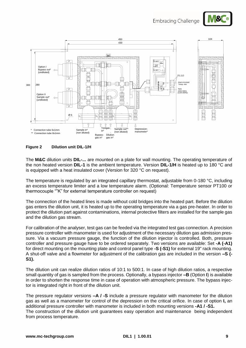
Figure 2 Dilution unit DIL-1/H
The M&C dilution units DIL-... are mounted on a plate for wall mounting. The operating temperature of the non heated version DIL-1 is the ambient temperature. Version DIL-1/H is heated up to 180 °C and is equipped with a heat insulated cover (Version for 320 °C on request). The temperature is regulated by an integrated capillary thermostat, adjustable from 0-180 °C, including an excess temperature limiter and a low temperature alarm. (Optional: Temperature sensor PT100 or thermocouple “”K” for external temperature controller on request) The connection of the heated lines is made without cold bridges into the heated part. Before the dilution gas enters the dilution unit, it is heated up to the operating temperature via a gas pre-heater. In order to protect the dilution part against contaminations, internal protective filters are installed for the sample gas and the dilution gas stream. For calibration of the analyser, test gas can be feeded via the integrated test gas connection. A precision pressure controller with manometer is used for adjustment of the necessary dilution gas admission pres-sure. Via a vacuum pressure gauge, the function of the dilution injector is controlled. Both, pressure controller and pressure gauge have to be ordered separately. Two versions are available: Set -A (-A1) for direct mounting on the mounting plate and control panel type -S (-S1) for external 19" rack mounting. A shut-off valve and a flowmeter for adjustment of the calibration gas are included in the version –S (-S1). The dilution unit can realize dilution ratios of 10:1 to 500:1. In case of high dilution ratios, a respective small quantity of gas is sampled from the process. Optionally, a bypass injector –B (Option I) is available in order to shorten the response time in case of operation with atmospheric pressure. The bypass injec-tor is integrated right in front of the dilution unit. The pressure regulator versions –A / -S include a pressure regulator with manometer for the dilution gas as well as a manometer for control of the depression on the critical orifice. In case of option I, an additional pressure controller with manometer is included in both mounting versions -A1 / -S1. The construction of the dilution unit guarantees easy operation and maintenance being independent from process temperature.
10 DIL1 | 1.00.01 www.mc-techgroup.com
7.1 VARIATIONS
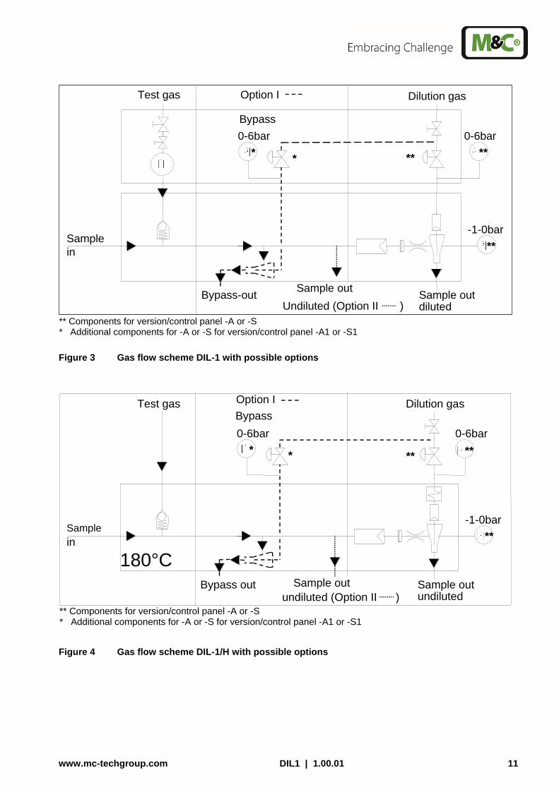
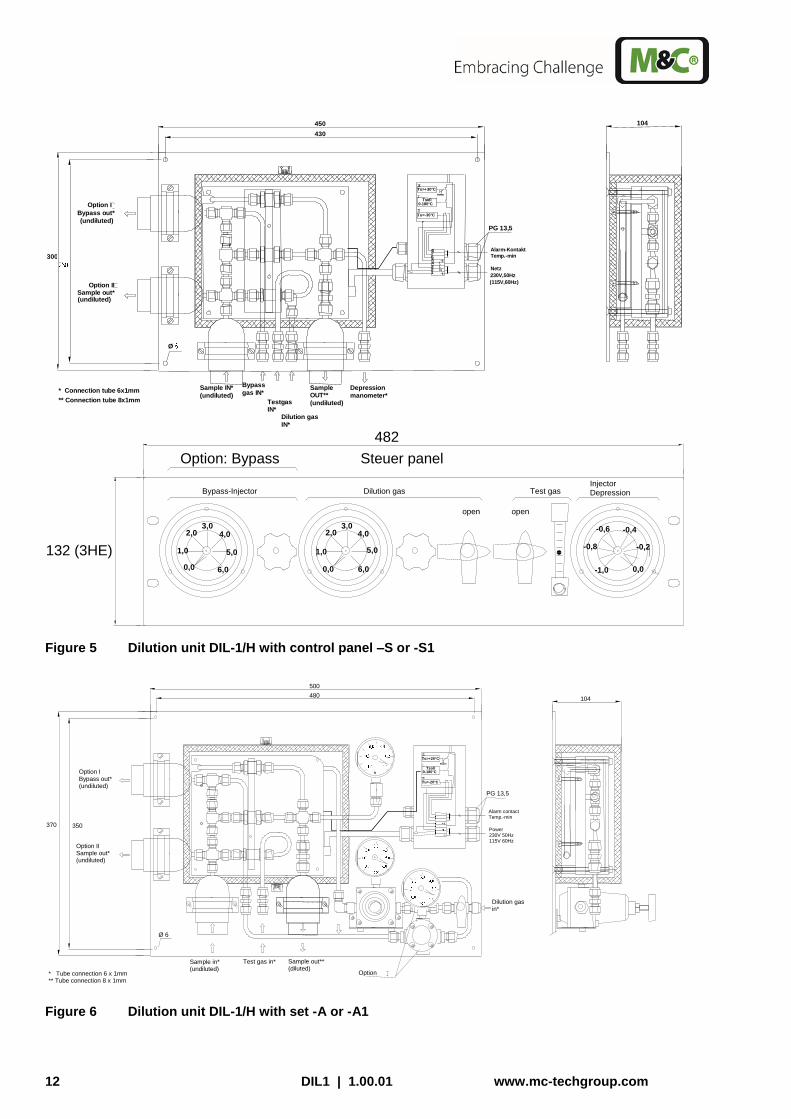
The two basic versions DIL-1 and DIL-1/H can be extended by several options. Option I Includes a bypass for dilution gas with bypass injector for a fast suction of sample gas in order to shorten for example the response time in case of high dilution ratios. Option II Includes an additional sample gas outlet „non-diluted“. Option –A Includes a pressure regulator with manometer and a manometer for control of the low pressure on the critical orifice. These are mounted directly onto the dilution unit. (see figure 6). Option –A1 Includes in addition to option -A a pressure regulator with manometer for operating the bypass of option I. This option is also mounted directly onto the dilution unit (see figure 6). Option –S Includes the necessary pressure regulator with manometer, shut-off valves and flowmeter, incorporated externally in a 19“ control panel (see figure 5). The connection of the sampling or the supply lines to the downstream analysis system have to be executed by the client. Connections which are marked accord-ingly are available on the back side of the 19“ unit. Option –S1 Includes in addition to option -S the pressure regulator with manometer for operating the bypass of option I, mounted externally into the 19“ control panel (see figure 5). The connection of the sampling or supply lines to the downstream analyse system has be made by the client. Connections which are marked accordingly are available on the back side of the 19” unit. The following illustrations show the gas flow of the dilution units DIL-1 and DIL-1/H with all possible options.
www.mc-techgroup.com DIL1 | 1.00.01 11
Bypass-out
Test gas
Sample
in
Sample out Sample out
Undiluted (Option II ) diluted
Dilution gas
-1-0bar
0-6bar
Option I
Bypass
0-6bar
*
**
** * **
** Components for version/control panel -A or -S * Additional components for -A or -S for version/control panel -A1 or -S1
Figure 3 Gas flow scheme DIL-1 with possible options
Bypass out
180°C
Sample
in
Test gas
Sample out undiluted (Option II )
Sample out
undiluted
Dilution gas
0-6bar
**
-1-0bar
0-6bar
*
Bypass
**
Option I
** *
** Components for version/control panel -A or -S * Additional components for -A or -S for version/control panel -A1 or -S1
Figure 4 Gas flow scheme DIL-1/H with possible options
12 DIL1 | 1.00.01 www.mc-techgroup.com
450 430
300
** Connection tube 8x1mm * Connection tube 6x1mm Bypass
gas IN* Sample IN*
(undiluted)
Ø
Sample OUT**
(undiluted)
Dilution gas
IN*
Testgas IN*
Depression
manometer*
Option II Sample out* (undiluted)
(undiluted)
Bypass out*
Option I
104
Alarm-Kontakt
230V,50Hz (115V,60Hz)
Temp.-min 3 2 1
L N
8 6 7 4 5 L’
Netz
Tsoll Tu<-30°C
0-180°C To>+30°C
Reset
PG 13,5
open
482 (84TE)
132 (3HE)
Option: Bypass
1,0 0,0 6,0
5,0
Bypass-Injector
3,0 2,0 4,0
Steuer panel
Dilution gas
1,0
0,0 6,0
5,0
3,0 2,0 4,0
open
-0,4
0,0
Injector Depression
-1,0
-0,8
Test gas
-0,6
-0,2
Figure 5 Dilution unit DIL-1/H with control panel –S or -S1
Option
500 480
370 350
Ø 6
Sample in* (undiluted)
Test gas in* Sample out** (diluted)
Option I Bypass out* (undiluted)
Dilution gas in*
104
PG 13,5
0-180°C
Tu<-20°C
To>+20°C Tsoll
Reset
Power 230V 50Hz 115V 60Hz
Alarm contact Temp.-min
Option II Sample out* (undiluted)
* Tube connection 6 x 1mm ** Tube connection 8 x 1mm Figure 6 Dilution unit DIL-1/H with set -A or -A1
www.mc-techgroup.com DIL1 | 1.00.01 13
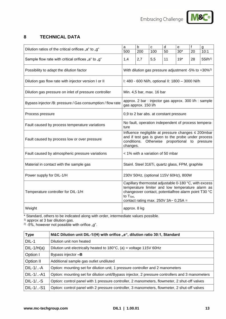
8 TECHNICAL DATA
Dilution ratios of the critical orifices „a“ to „g“ a b c d e f g
500 200 100 50 30* 20 10:1
Sample flow rate with critical orifices „a“ to „g“ 1,4 2,7 5,5 11 19* 28 55l/h1)
Possibility to adapt the dilution factor With dilution gas pressure adjustment -5% to +30%2)
Dilution gas flow rate with injector version I or II I: 480 - 600 Nl/h, optional II: 1800 – 3000 Nl/h
Dilution gas pressure on inlet of pressure controller Min. 4,5 bar, max. 16 bar
Bypass injector /B: pressure / Gas consumption / flow rate approx. 2 bar : injector gas approx. 300 l/h : sample gas approx. 150 l/h
Process pressure 0,9 to 2 bar abs. at constant pressure
Fault caused by process temperature variations No fault, operation independent of process tempera-ture
Fault caused by process low or over pressure
Influence negligible at pressure changes ≤ 200mbar and if test gas is given to the probe under process conditions. Otherwise proportional to pressure changes.
Fault caused by atmospheric pressure variations < 1% with a variation of 50 mbar
Material in contact with the sample gas Stainl. Steel 316Ti, quartz glass, FPM, graphite
Power supply for DIL-1/H 230V 50Hz, (optional 115V 60Hz), 800W
Temperature controller for DIL-1/H
Capillary thermostat adjustable 0-180 °C, with excess temperature limiter and low temperature alarm as changeover contact, potentialfree alarm point T30 °C to TSet, contact rating max. 250V 3A~ 0,25A =
Weight approx. 8 kg
* Standard, others to be indicated along with order, intermediate values possible. 1) approx at 3 bar dilution gas. 2) -5%, however not possible with orifice „g“.
Type M&C Dilution unit DIL-1/(H) with orifice „e“, dilution ratio 30:1, Standard
DIL-1 Dilution unit non heated
DIL-1/H(a) Dilution unit electrically heated to 180°C, (a) = voltage 115V 60Hz
Option I Bypass injector –B
Option II Additional sample gas outlet undiluted
DIL-1/..-A Option: mounting set for dilution unit, 1 pressure controller and 2 manometers
DIL-1/..-A1 Option: mounting set for dilution unit/Bypass injector, 2 pressure controllers and 3 manometers
DIL-1/..-S Option: control panel with 1 pressure controller, 2 manometers, flowmeter, 2 shut-off valves
DIL-1/..-S1 Option: control panel with 2 pressure controller, 3 manometers, flowmeter, 2 shut-off valves

14 DIL1 | 1.00.01 www.mc-techgroup.com
9 DILUTION PRINCIPLE
The functional principle of the dilution unit is based on ultrasonic flow through a critical orifice (see Fig. 4). The flow through the orifice is constant when the differential pressure via the orifice is higher than 500 mbar. For the atmospheric inlet pressure (Pin = 1020 mbar), this means a pressure at the orifice outlet (Pout) of less than 520 mbar absolute. The necessary vacuum at the orifice outlet is produced by an injector operated with dilution gas. Depending on the critical orifice selected, dilution rates can be between 10:1 and 500:1. The table be-low gives an overview of the dilution factor and sample gas volume using the injector I (480 – 600 Nl/h):
Orifice type a b c d e f g
Dilution ratio* 500:1 200:1 100:1 50:1 30:1 20:1 10:1
Volume flow through the orifice [Nl/h] 1,4 2,7 5,5 11 19 28 55 * with Injector II 50:1 to 2000:1
Figure 7 Dilution principle
How to check the dilution ratios and the exact adjustment of the pressure conditions are described in chapter 14.1.
www.mc-techgroup.com DIL1 | 1.00.01 15
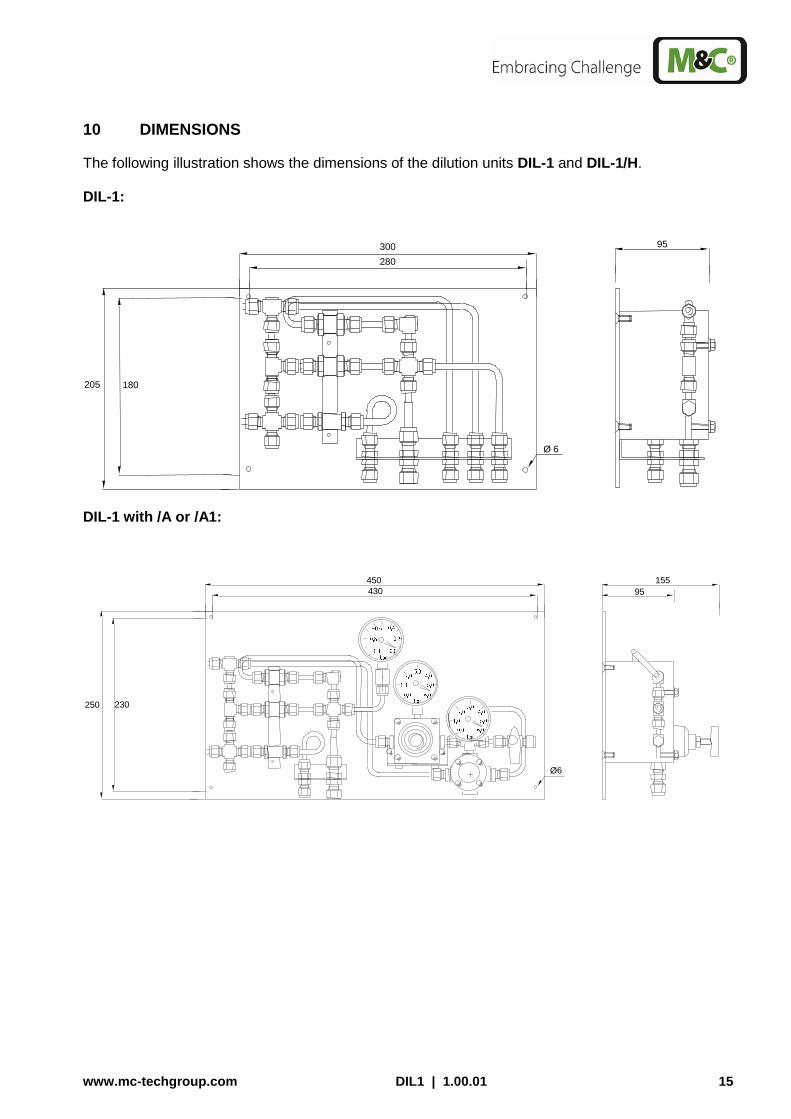
10 DIMENSIONS
The following illustration shows the dimensions of the dilution units DIL-1 and DIL-1/H. DIL-1:
300 280
205 180
95
Ø 6
DIL-1 with /A or /A1:
450
430
250 230
Ø6
155
95
16 DIL1 | 1.00.01 www.mc-techgroup.com
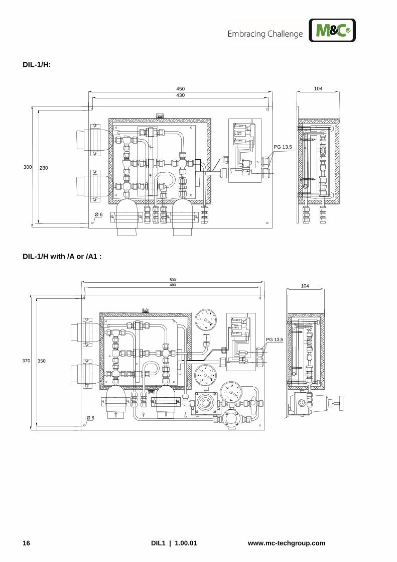
DIL-1/H:
450
430
300 280
Ø 6
Tsoll
Tu<-30°C
0-180°C To>+30°C
Reset
PG 13,5
104
DIL-1/H with /A or /A1 :
500 480
370 350
Ø 6
104
PG 13,5
0-180?C Tu<-30°C
To>+30°C
Tsoll Reset

www.mc-techgroup.com DIL1 | 1.00.01 17
Option control panel –S or -S1:
Auf Open
482 (84TE)
132 (3HE)
Option: Bypass
1,0
0,0 6,0
5,0
Bypass-Injector
Beipass-Injektor
3,0 2,0 4,0
Steuerpanel
Dilution gas Verdünnungsgas
1,0
0,0 6,0
5,0
3,0 2,0 4,0
Auf Open
-0,4
0,0
Injektor-Unterdruck Injector-vacuum
-1,0
-0,8
Test gas Prüfgas
-0,6
-0,2
Figure 8 Dimensions (mm) dilution units DIL–1.. and control panel –S or –S1
Figure 9 DIL-1 with control panel -S1
Back pressure max. 1,2 bar abs.
Sample gas IN

18 DIL1 | 1.00.01 www.mc-techgroup.com
11 RECEIPT AND STORAGE
Carefully remove the dilution unit and any accessories from the transport packaging immediately after receipt and check the completeness of the delivery against the packing list.
Check the goods for possible transport damages and, if necessary, notify immediately your transport insurer of any damage.
NOTE!
The dilution unit should be stored in a protected, frost-free room!
12 INSTALLATION INFORMATION
The safety rules and regulations for the prevention of accidents must be observed during installation and also subsequent operation. The information in chapter 3 “Important Safety Information“ must be observed. The following also applies:
Select the optimal sampling point according to the generally applicable directives or coordinate with the responsible departments.
NOTE!
The dilution unit must be checked for its suitability for use with the available operating parameters prior to installation (see type plate).
13 INSTALLATION
The M&C dilution units DIL-1... are designed for stationary use. With correct selection of the sample point and proper installation, they will work for many years with a minimum of maintenance required.
13.1 CONNECTION OF THE SUPPLY OR SAMPLE LINES
NOTE!
Increases of pressure due to use of long sample gas lines at the outlet may have a great influence on the measuring result. For this reason, we recom-mend the following nominal widths and lengths for the sample lines in de-pendence on the type of injector: Injector type I:
i 6mm max. 50m
i 8mm max. 150m
Injector type II:
i 8mm max. 15m
i 10mm max. 40m
i 12mm max. 80m
www.mc-techgroup.com DIL1 | 1.00.01 19
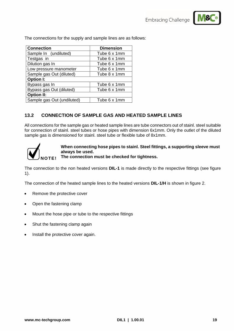
The connections for the supply and sample lines are as follows:
Connection Dimension
Sample In (undiluted) Tube 6 x 1mm
Testgas in Tube 6 x 1mm
Dilution gas In Tube 6 x 1mm
Low pressure manometer Tube 6 x 1mm
Sample gas Out (diluted) Tube 8 x 1mm
Option I:
Bypass gas In Tube 6 x 1mm
Bypass gas Out (diluted) Tube 6 x 1mm
Option II:
Sample gas Out (undiluted) Tube 6 x 1mm
13.2 CONNECTION OF SAMPLE GAS AND HEATED SAMPLE LINES
All connections for the sample gas or heated sample lines are tube connectors out of stainl. steel suitable for connection of stainl. steel tubes or hose pipes with dimension 6x1mm. Only the outlet of the diluted sample gas is dimensioned for stainl. steel tube or flexible tube of 8x1mm.
NOTE!
When connecting hose pipes to stainl. Steel fittings, a supporting sleeve must always be used. The connection must be checked for tightness.
The connection to the non heated versions DIL-1 is made directly to the respective fittings (see figure 1). The connection of the heated sample lines to the heated versions DIL-1/H is shown in figure 2.
Remove the protective cover
Open the fastening clamp
Mount the hose pipe or tube to the respective fittings
Shut the fastening clamp again
Install the protective cover again.
20 DIL1 | 1.00.01 www.mc-techgroup.com
13.3 CONNECTION OF DILUTION GAS OR BYPASS GAS
For connection of the supply lines, tube connectors with dimension 6 x 1mm are available. mm zur Verfügung. The connection fittings of the heated dilution units are located outside the cover and can be connected without disassembly. Only when using the heated versions and option I, a heated “undiluted” sample line is connected to the bypass outlet. Please act as follows:
Remove protective cover
Open the fastening clamp
Mount the hose pipe or tube to the respective fitting
Shut the fastening clamp again
Install the protective cover again. When using option –A (only dilution gas) or –A1 (dilution and bypass gas), the supply lines are con-nected to the connection fittings of the precision pressure regulator. When using the 19“ control panels –S or –S1, corresponding connectors for the supply gases are pro-vided at the rear of the unit.
13.4 CONNECTION OF CALIBRATION GAS
For all versions of DIL-1 and DIL-1/H, a tube connector 6 x 1 mm is available for connection of the calibration gas (see figure 4).
13.5 ELECTRICAL CONNECTION
The temperature setting on the dilution unit DIL-1/H is made on the internal capillary thermostate.
W A R N I N G !
The incorrect mains voltage can destroy the unit. Check the type plate for the correct voltage prior to connection!
The dilution units must be mounted in such a way that touching the live parts is excluded!
In any case, we recommend the use of temperature resistant cables!
The alarm contact for low temperature must be controlled!
In case of a low temperature alarm (failure of heating or sensor) the dilution gas or bypass gas supply must be interrupted to avoid seri-ous damage of the dilution unit. We recommend to switch the low temperature alarm onto external solenoid valves that provide the above mentioned function!
NOTE!
For the erection of power installations with nominal voltages of up to 1000V, the requirements of VDE 0100 and its associated standards and specifications must be observed. A main switch must be provided externally.

www.mc-techgroup.com DIL1 | 1.00.01 21
The supply circuit of the unit must be equipped with a fuse with the correct rating (over current protection); the electrical details see technical data.
Remove cover of the connection box.
Insert the mains cable (min. 3 x 1,5 mm2) through the cable gland and connect to the appropriate terminals.
Insert the signal cable (low temperature alarm) through the cable gland and connect to the appro-priate terminals (contact position Tu shows alarm event).
Screw cover back in place.
Mains 230V 50Hz or 115V 60Hz
Alarm outlet
1
2
1 2
+30
-30 800 W
Figure 10 Electrical connection for DIL-1/H..
W A R N I N G !
We recommend the use of temperature resistent cables!
14 INITIAL STARTING
Prior to initial use, system and process-specific safety measures must be observed. The relevant safety requirements and procedures for the medium to be sampled must be heeded.
22 DIL1 | 1.00.01 www.mc-techgroup.com
W A R N I N G !
The supply of gas to the injectors is only allowed when the heated dilution unit has reached its operating temperature (see technical data).
Prior to initial use, make sure that the mains voltage corresponds to the voltage indicated on the type plate!
Do not touch the surface of the heated dilution unit during operation. Due tp its high surface temperatures, it may cause burns. Protective gloves must be worn and the dilution unit must be protected against unauthorised access!
The following step-by-step procedure is recommended:
If possible, separate the dilution unit from the sample point, eg. above the ball valve.
In case of heated versions, check the set temperature on the installed thermostat.
NOTE!
If the set temperature on the capillary controller should be reduced by more than 30°C in one step, the excess temperature cut-off on the thermostat is activated (for re-starting press the reset button).
For heated versions, switch on the mains voltage.
NOTE!
The total heating time is about 2 hours. After about 1 hour, the lower threshold value ( 30°C below set value) is exceeded.
Open the valve for the dilution gas (for heated version: wait until the complete dilution unit is heated, approx. 2 h). Set the precision pressure reducer to the pressure specified on the enclosed injector data sheet (see figure 9).
NOTE!
For safety reasons, the low pressure gauge must show a low pres-sure of >-0,6 bar. With a low pressure of < -0, 6 bar, the critical orifice will not function properly. If the necessary low pressure will not be reached, the dilution gas supply pressure must be increased.
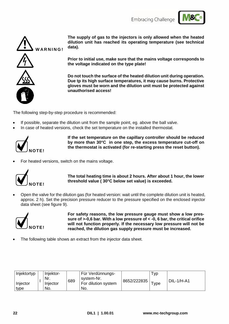
The following table shows an extract from the injector data sheet.
Injektortyp
I
Injektor-Nr.
689
Für Verdünnungs-system-Nr.
8652/222835
Typ
DIL-1/H-A1 Injector type
Injector No.
For dilution system No.
Type

www.mc-techgroup.com DIL1 | 1.00.01 23
Betriebsdruck Operating pres-
sure [bar]
Durchfluss Flow [l/h]
Unterdruck ohne kritische Düse Vacuum without critical orifice
[bar]
Unterdruck mit kritischer Düse Vacuum with critical orifice 5,1l/h [bar]
2,4 415 -0,62 -0,61
2,6 435 -0,65 -0,64
2,8 460 -0,68 -0,67
3,0 490 -0,80 -0,77
3,2 510 -0,79 -0,77
3,4 535 -0,79 -0,77
3,6 560 -0,78 -0,76
3,8 585 -0,77 -0,76
4,0 605 -0,77 -0,75
Überprüfung des Verdünnungsfaktors Check of the dilution ratio
Messgasdruck atmosphärisch Sample gas pressure atmospheric
Kritische Düse Critical nozzle
Verd.gas Dilution gas
Verdünnungsgasdruck Dilution gas pressure
Messgas Sample
Verdünnung Dilution
Messwert d. verd. Gases Meas. value of the dil. gas
5,1 l/h 100% N2 3,2 bar 100% O2 100:1 1,0 % O2
Figure 11 Extract from the injector data sheet
For the operation of an installed bypass injector, the necessary pressure must be set on the pressure regulator (see figure 12).
NOTE!
The attached bypass injector table shows the suction flows at corre-sponding bypass gas pressures for two different process pressures, 1 bar and 0,9 bar absolute (see figure 12).
Bypassgas / Bypass gas Prozessgas / Sample gas Betriebsdruck
Operating pressure [bar]
Durchfluss Flow [l/h]
Ansaugvolumenstrom bei 1bar abs. Suction flow at 1bar abs.
[l/h]
Ansaugvolumenstrom bei 0,9bar abs.
Suction flow at 0,9bar abs. [l/h]
0,5 110 45 -
1,0 155 115 -
1,5 190 200 65
2,0 235 250 135
2,5 270 300 200
3,0 310 350 250
3,5 355 370 270
4,0 395 390 305
4,5 430 425 350
Figure 12 Suction flow at 0,9 or 1bar abs. in dependence on the bypass gas pressure
W A R N I N G !
In the event of low temperature (failure of the heating) the supply of dilution gas must be interrupted!
14.1 CALIBRATION
A calibration of the downstream analyser system or checking the dilution factor must always be effected under operation conditions. Above the test gas valve, an appropriate test gas can be feeded.

24 DIL1 | 1.00.01 www.mc-techgroup.com
W A R N I N G !
The gas pressure must be above 0,7 bar, because the pressure con-trol valve installed has an opening pressure of 0, 7 bar.
When using the control panel, the respective ball valve for the test gas supply must be opened and the flow rate be set on the flowme-ter.
The procedure for calibration or checking the dilution ratio is as follows:
Supply test gas of a concentration you know.
Check the dilution ratio on the downstream analyser and, if necessary, correct the pressure on the pressure regulator of the dilution gas.
Test gas feeding without bypass injector In order to assure that sufficient test gas is available, the test gas quantity should be at least threefold of the flow quantity passing through the critical orifice (see injector data sheet). Test gas feeding with bypass injector The test gas quantity must be approximately 10% above the quantity of the volume flow passing though the bypass (see figure 12) and the critical orifice (see figure 11).
15 CLOSING DOWN
Prior to closing down, the heated dilution unit should be purged with inert gas or air to prevent the condensation of agressive components from the process gas.
www.mc-techgroup.com DIL1 | 1.00.01 25
16 MAINTENANCE
Prior to any maintenance of repairing works, system and process specific safety measures must be observed.
W A R N I N G !
Agressive condensate possible. Wear safety glasses and appropri-ate protective clothing!
Do not touch the surface of the dilution unit during operation as this can cause burns due to the high surface temperatures. Wear protec-tive gloves. The dilution unit must be protected against unauthorized access!
Before carrying out maintenance work on electrical components, the mains voltage must be disconnected in all poles. This also applies to any connected alarm and control circuits !
No recommendation for maintenance intervals can be given. Maintenance intervals must be determined depending on the particular process conditions and specific application. The maintenance of the dilution unit is limited mainly to the cleaning of the filter elements, inspection of the seals and maintenance of the dilution systems.
NOTE!
The dilution unit does not need to be removed for repair or mainte-nance.
26 DIL1 | 1.00.01 www.mc-techgroup.com
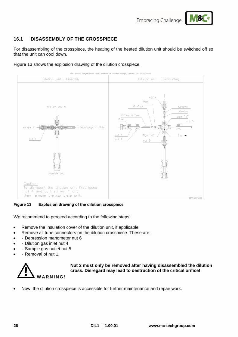
16.1 DISASSEMBLY OF THE CROSSPIECE
For disassembling of the crosspiece, the heating of the heated dilution unit should be switched off so that the unit can cool down. Figure 13 shows the explosion drawing of the dilution crosspiece.
Figure 13 Explosion drawing of the dilution crosspiece
We recommend to proceed according to the following steps:
Remove the insulation cover of the dilution unit, if applicable;
Remove all tube connectors on the dilution crosspiece. These are:
- Depression manometer nut 6
- Dilution gas inlet nut 4
- Sample gas outlet nut 5
- Removal of nut 1.
W A R N I N G !
Nut 2 must only be removed after having disassembled the dilution cross. Disregard may lead to destruction of the critical orifice!
Now, the dilution crosspiece is accessible for further maintenance and repair work.
www.mc-techgroup.com DIL1 | 1.00.01 27
16.2 CLEANING OF THE CRITICAL ORIFICE AND CHECK OR CHANGE OF THE O-RINGS
W A R N I N G !
Do not clean the critical orifice mechanically.
Cleaning should be effected in an ultrasonic bath !
Figure 13 shows the position of the orifice in the crosspiece and the O-ring seals.
Figure 14 Crosspiece with critical orifice and O-ring seals
Please proceed as follows:
Loosen union nut 3 and remove the jet pipe;
Loosen nut 2 and remove the pipe piece with both nuts;
Push the injection nozzle out of the jet pipe side by using the mounting tools (item 8, figure 14);
Push the critical orifice with its nozzle seat and o-ring carefully from the back side of the crosspiece by using the mounting tool (item 8, figure 14);
Check the o-rings and change them if necessary;
Push the new orifice or the cleaned old one into the o-rings until block.
Now, the dilution unit can be reassembled in reverse order.
W A R N I N G !
The Swagelok® fittings must be carefully tightened to avoid damage of the internal components. Do not tighten the fittings too fast.
If a fitting is believed to be leaking, do not tighten further. Disassem-ble the fitting completely and tighten it again.
8
28 DIL1 | 1.00.01 www.mc-techgroup.com
16.3 CHANGE AND CLEANING OF THE INJECTION NOZZLE
NOTE!
For cleaning the injector, it is not necessary to remove the nozzle out of the crosspiece. The nozzle can be cleaned together with the complete crosspiece in an ultrasonic bath.
For changing the injector nozzle, see figure 14:
Loosen nut 3 and remove jet pipe;
Push the injection nozzle out of the jet pipe side by using the mounting tools (item 8, figure 14);
Check the o-ring and change it if necessary;
Push the new nozzle with o-ring until blocking.
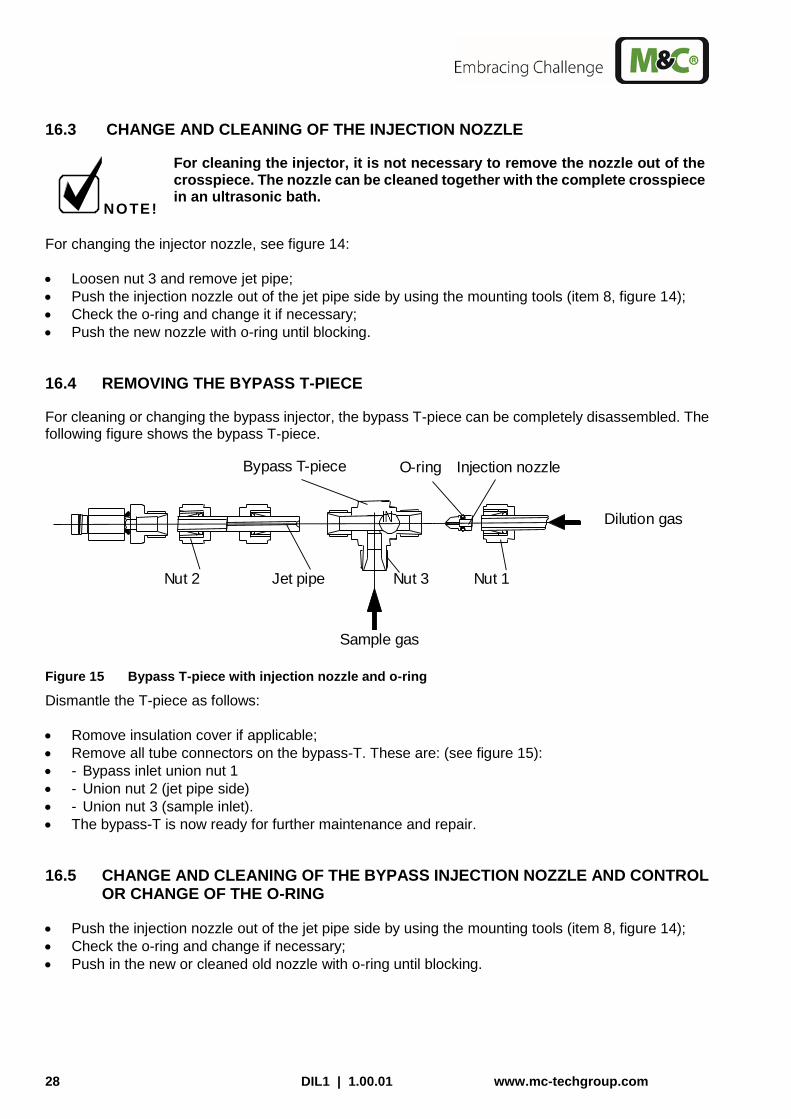
16.4 REMOVING THE BYPASS T-PIECE
For cleaning or changing the bypass injector, the bypass T-piece can be completely disassembled. The following figure shows the bypass T-piece.
Injection nozzle O-ring Bypass T-piece
Jet pipe Nut 2 Nut 1 Nut 3
Sample gas
Dilution gas
Figure 15 Bypass T-piece with injection nozzle and o-ring
Dismantle the T-piece as follows:
Romove insulation cover if applicable;
Remove all tube connectors on the bypass-T. These are: (see figure 15):
- Bypass inlet union nut 1
- Union nut 2 (jet pipe side)
- Union nut 3 (sample inlet).
The bypass-T is now ready for further maintenance and repair.
16.5 CHANGE AND CLEANING OF THE BYPASS INJECTION NOZZLE AND CONTROL OR CHANGE OF THE O-RING
Push the injection nozzle out of the jet pipe side by using the mounting tools (item 8, figure 14);
Check the o-ring and change if necessary;
Push in the new or cleaned old nozzle with o-ring until blocking.
www.mc-techgroup.com DIL1 | 1.00.01 29
NOTE!
For cleaning the injection nozzle, you need not necessarily pull the nozzle out of the T-piece. The nozzle can be cleaned together with the complete T-piece in an ultrasonic bath.
If you blow through the nozzle, this must be done from the jet pipe side.
17 SPARE PARTS LIST
The wear, tear and spare part requirements depend on the specific operating conditions. The following table shows an extract of the recommended spare parts for the diluiton units DIL-1 and DIL-1/H :
Recommended spare parts
Part No. Description
20 S 4300 Complete set critical orifice incl. 2x o-rings. Material: glass # Please specify dilution ratio along with order. #
93 S 4000 Injection nozzle incl. o-ring (crosspiece)
93 S 4006 Dilution crosspiece empty, without any inserts, material: SS316
93 S 4016 Bypass T-piece empty, without any inserts, material: SS316
93 S 4020 Crosspiece complete. # Please specify dilution ration along with order #
93 S 4025 Bypass T-piece complete
93 S 4035 Suction tube for DIL 6x1 mm with integrated filter sieve incl. Swagelok® nuts, silver-plate cutting ring for dilution crosspiece, material SS316
93 S 0010 Spare thermostate 0-180°C
93 S 0015 Spare heating cartridge HLP, 230 V 800 W
93 S 0017 Spare heating cartridge HLP, 115 V 800 W
93 S 0018 Heat conductivity paste for insertion of heating cartridge
93 S 4015 Eductor incl. O-ring for bypass-T-piece
18 APPENDIX
Further documentation of our products can be seen in our internet catalogue: www.mc-techgroup.com


![Bypass gastri corregidoo[1]](https://static.fdocuments.net/doc/165x107/55b800ffbb61ebe37c8b467d/bypass-gastri-corregidoo1-55bd331ceab27.jpg)


