DIGITAL PREDISTORTION BASED ON ENVELOPE FEEDBACKkalman.kaist.ac.kr/assets/papers/06288588.pdf ·...
4
DIGITAL PREDISTORTION BASED ON ENVELOPE FEEDBACK Jinhyun So † , Sungho Choi †† , Seung Hyeok Ahn † , Eui-Rim Jeong ††† , and Yong H. Lee † Dept. of Electrical Engineering KAIST, South Korea † Agency for Defense Development, South Korea †† Dept. of Electrical Engineering Hanbat Uinversity, South Korea ††† ABSTRACT A new digital predistortion (DPD) technique based on enve- lope feedback is proposed for linearization of power ampli- fiers (PAs). Unlike conventional DPD techniques that need frequency down converters (FDCs) in the feedback path to recover the complex envelope of the PA output, the proposed technique does not need an FDC. Instead it employs two enve- lope detectors, estimating the envelope of the PA output and that of the difference signal between the PA input and the PA output. It is shown that the complex envelope of the PA output can be estimated from the two envelope feedbacks if the sign of the phase distortion of the AM-PM characteristic remains the same for all PA input magnitudes. Simulation results show that the performance of the proposed DPD is comparable to the conventional DPD employing an FDC. Index Terms— Envelope feedback, indirect learning, polynomial, power amplifier(PA), predistortion 1. INTRODUCTION A power amplifier (PA) is an indispensable component to transmit signals to a remote destination in wireless commu- nications. To ensure good signal quality at the PA output, linear PAs are required. However, PAs are generally nonlin- ear devices causing problems such as spectral regrowth (or spectral broadening) and inband signal distortion: the former increases inter-channel interference and the latter degrades signal quality often measured by the error vector magnitude (EVM) [1]. To overcome these difficulties caused by the non- linearity, many linearization techniques have been proposed, including analog/digital predistortion, feedforward, and feed- back methods [2]. Among them, DPD has been recognized as a powerful tool that can exhibit excellent linearization characteristics. However, use of DPD is limited because of its complexity in implementation: DPD needs an FDC in the feedback path, which is not simple to implement, to recover the complex envelope of the PA output. The objective of this This research was supported by the KCC (Korea Communications Com- mission), Korea, under the R&D program supervised by the KCA (Korea Communications Agency) (KCA-2011-08913-04001). paper is to develope a DPD technique that does not require an FDC. The proposed DPD employs two envelope detectors in- stead of an FDC; they detect the envelope of the PA output and that of the difference signal between the PA input and output. It is shown that the complex envelope of the PA out- put can be estimated using the two envelopes if the sign of the phase difference between PA’s input and output signals, which is the phase distortion given by the AM-PM character- istic curve, remains the same for all magnitude values of the PA input. This condition on the sign of the phase distortion, which will be referred to as the phase sign condition , is sat- isfied by many practical PAs [3], [4]. Simulation results show that the performance of the proposed DPD is comparable to the conventional DPD employing an FDC. Since the envelope detectors are considerably simpler to implement than an FDC, the proposed DPD is a useful alternative to the conventional DPD when the PA meets the phase sign condition. The organization of this paper is as follows. Section 2 describes a transmitter model employing the proposed enve- lope feedback. The proposed DPD is developed in Section 3. Section 4 and Section 5 presents the simulation results and conclusion, respectively. 2. DPD STRUCTURE AND SIGNAL MODEL Fig. 1 compares the proposed DPD structure with the conven- tional one. The two structures are essentially the same with the exception that the former employs two envelope detectors in the feedback path while the latter employs an FDC. The envelope detectors of the proposed scheme estimate the en- velope of the PA output (feedback 2 in Fig. 1(b)) and that of the difference signal between PA input and the PA output (feedback 1 in Fig. 1(b)). Using these two feedback informa- tion, we extract exact amplitude and phase information of PA output as described in the next section. To derive the equiv- alent model of the transmitter in Fig. 1(b), we consider the memoryless power series PA model [2]. For simplicity, third order model is considered but extension to higher order PA is straightforward. Let y(t) and a(t) be the input and output of the PA, respectively, and G(·) denote the PA’s nonlinear 3169 978-1-4673-0046-9/12/$26.00 ©2012 IEEE ICASSP 2012
Transcript of DIGITAL PREDISTORTION BASED ON ENVELOPE FEEDBACKkalman.kaist.ac.kr/assets/papers/06288588.pdf ·...
DIGITAL PREDISTORTION BASED ON ENVELOPE FEEDBACK
Jinhyun So†, Sungho Choi††, Seung Hyeok Ahn†, Eui-Rim Jeong†††, and Yong H. Lee†
Dept. of Electrical Engineering KAIST, South Korea†
Agency for Defense Development, South Korea ††
Dept. of Electrical Engineering Hanbat Uinversity, South Korea †††
ABSTRACT
A new digital predistortion (DPD) technique based on enve-
lope feedback is proposed for linearization of power ampli-
fiers (PAs). Unlike conventional DPD techniques that need
frequency down converters (FDCs) in the feedback path to
recover the complex envelope of the PA output, the proposed
technique does not need an FDC. Instead it employs two enve-
lope detectors, estimating the envelope of the PA output and
that of the difference signal between the PA input and the PA
output. It is shown that the complex envelope of the PA output
can be estimated from the two envelope feedbacks if the sign
of the phase distortion of the AM-PM characteristic remains
the same for all PA input magnitudes. Simulation results show
that the performance of the proposed DPD is comparable to
the conventional DPD employing an FDC.
Index Terms— Envelope feedback, indirect learning,
polynomial, power amplifier(PA), predistortion
1. INTRODUCTION
A power amplifier (PA) is an indispensable component to
transmit signals to a remote destination in wireless commu-
nications. To ensure good signal quality at the PA output,
linear PAs are required. However, PAs are generally nonlin-
ear devices causing problems such as spectral regrowth (or
spectral broadening) and inband signal distortion: the former
increases inter-channel interference and the latter degrades
signal quality often measured by the error vector magnitude
(EVM) [1]. To overcome these difficulties caused by the non-
linearity, many linearization techniques have been proposed,
including analog/digital predistortion, feedforward, and feed-
back methods [2]. Among them, DPD has been recognized
as a powerful tool that can exhibit excellent linearization
characteristics. However, use of DPD is limited because of
its complexity in implementation: DPD needs an FDC in the
feedback path, which is not simple to implement, to recover
the complex envelope of the PA output. The objective of this
This research was supported by the KCC (Korea Communications Com-
mission), Korea, under the R&D program supervised by the KCA (Korea
Communications Agency) (KCA-2011-08913-04001).
paper is to develope a DPD technique that does not require an
FDC.
The proposed DPD employs two envelope detectors in-
stead of an FDC; they detect the envelope of the PA output
and that of the difference signal between the PA input and
output. It is shown that the complex envelope of the PA out-
put can be estimated using the two envelopes if the sign of
the phase difference between PA’s input and output signals,
which is the phase distortion given by the AM-PM character-
istic curve, remains the same for all magnitude values of the
PA input. This condition on the sign of the phase distortion,
which will be referred to as the phase sign condition , is sat-
isfied by many practical PAs [3], [4]. Simulation results show
that the performance of the proposed DPD is comparable to
the conventional DPD employing an FDC. Since the envelope
detectors are considerably simpler to implement than an FDC,
the proposed DPD is a useful alternative to the conventional
DPD when the PA meets the phase sign condition.
The organization of this paper is as follows. Section 2
describes a transmitter model employing the proposed enve-
lope feedback. The proposed DPD is developed in Section
3. Section 4 and Section 5 presents the simulation results and
conclusion, respectively.
2. DPD STRUCTURE AND SIGNAL MODEL
Fig. 1 compares the proposed DPD structure with the conven-
tional one. The two structures are essentially the same with
the exception that the former employs two envelope detectors
in the feedback path while the latter employs an FDC. The
envelope detectors of the proposed scheme estimate the en-
velope of the PA output (feedback 2 in Fig. 1(b)) and that
of the difference signal between PA input and the PA output
(feedback 1 in Fig. 1(b)). Using these two feedback informa-
tion, we extract exact amplitude and phase information of PA
output as described in the next section. To derive the equiv-
alent model of the transmitter in Fig. 1(b), we consider the
memoryless power series PA model [2]. For simplicity, third
order model is considered but extension to higher order PA
is straightforward. Let y(t) and a(t) be the input and output
of the PA, respectively, and G(·) denote the PA’s nonlinear
3169978-1-4673-0046-9/12/$26.00 ©2012 IEEE ICASSP 2012

characteristic, then the PA output can be written as follows:
a(t) = G(y(t)) = BPF{α1y(t)+α2y2(t)+α3y
3(t)}, (1)
where {αi} are real coefficients characterizing the PA and
BPF{·} denotes bandpass filtering around the carrier fre-
quency ωc. Substituting y(t) = Re{yb(t)ejωct} (where sub-
script ’b’ means the baseband signal) in (1), we can see that
the nonlinearity of PA causes nonlinear distortion at funda-
mental frequency ωc and generates harmonic signals at DC,
2ωc, and 3ωc. By bandpass filtering, harmonics are filtered
out and the PA output can be written as
a(t) = Re{ab(t)e
jωct}, (2)
where ab(t) is the baseband equivalent PA output given by
ab(t) � Gb(yb(t)) = (w1 + w2|yb(t)|2)yb(t). Gb(·) is the
baseband equivalent PA characteristic function and w1 = α1,
w2 = 3α3
22 . In general, the coefficients {wi} characterizing
the PA are complex values since real PA have some delay el-
ements in (1). For mathematical modeling of envelope detec-
tor, either the square-law envelope detector or the envelope
detector using the Hilbert transform can be used [5]. In this
paper, we consider the square-law envelope detector which is
represented as√LPF{2× (·)2} (here LPF{·} means low
pass filtering). Then, the feedback signal at the first path is
written as
f1(t) = |yb(t)− ab(t)/K| , (3)
where K is the attenuation factor. Similarly, the envelope
signal at the second path is
f2(t) = |ab(t)/K| . (4)
From (2)–(4), the baseband equivalent transmitter model can
be represented as Fig. 2.
3. DESIGN OF PROPOSED DPD
In this section, we first show that the PA output signal
ab(n)/K can be estimated from the two envelop signals.
Then the proposed DPD algorithm based on the estimated
PA output signal is derived. Specifically, a polynomial-based
DPD with indirect learning algorithm is developed.
3.1. PA Output Estimation
Referring to Fig. 2, our objective is to obtain ab(n) =|ab(n)|ej∠(ab(n)) from the two envelope signals. Since
|ab(n)| can be obtained directly from the second feedback
path, we need to estimate the phase of ab(n). Note that the
signals that we have are |ab(n)/K|, |yb(n) − ab(n)/K|, and
yb(n). Fig. 3 shows the relationship among ab(n)/K, yb(n),
DAC
cos(wct)
-sin(wct)
+
+
BPF
BPF
PA
DPD
parameter
extraction
DPD
ADC
cos(wct)
sin(wct)
LPF
LPF
DAC
ADC
Freq. Down-conv.
Feedback
Attenuator
bx n
Ry n
Iy n
Ry t
1/ K
Iy t
a t
/a t K
Ry t
Iy t
Ry n
Iy n
y t
G
b R Iy n y n jy n
Freq. Up-conv.
(a)
DAC
cos(wct)
-sin(wct)
+
+
BPF
BPF
PA
DPD
parameter
extraction
DPD
ADCEnvelope
Detector
Envelope
Detector
DAC
ADC
Envelope Detection
Feedback
Feedback_1
Attenuator
bx n
Ry n
Iy n
Ry t
1/ K
Iy t
a t
/a t K
y t
G
Feedback_2
2f t
1f t
b R Iy n y n jy n
+-
Freq. Up-conv.
(b)
Fig. 1. (a) A conventional transmitter model employing DPD
using an FDC in feedback path. (b) Proposed DPD structure
using envelope detection in feedback path.
and yb(n) − ab(n)/K in complex domain. Define θ �∠(ab(n))− ∠(yb(n)). Then, |θ| can be obtained (Fig. 3) as
|θ| = cos−1
(|yb(n)|2 + |ab(n)
K |2 − |yb(n)− ab(n)K |2
2|yb(n)||ab(n)K |
).
(5)
Thus, the absolute phase difference between the PA input and
the PA output can be obtained. If the sign of the phase differ-
ence θ remains the same for all PA input magnitude |yb(n)|(i.e., the phase sign condition is met) and the sign is known a
priori, then θ can be obtained from (5) and the PA output is
given by
ab(n) = |ab(n)|ej(∠(yb(n))+θ). (6)
The phase sign condition is met for typical TWTA PAs but
the condtion is not always satisfied for LDMOS PAs [4].
3.2. PD Algorithm
Given the PA output estimate, the proposed DPD is developed
following the steps for designing conventional DPD [6]– [8].
In this paper, a polynomial-based DPD is employed and its
parameters are estimated by indirect learning methods. Ex-
tending the baseband model in (2) to a higher order case, PA
3170

PA
Attenuator
bx n
1/ K
ba n
/b
a n K
by n
bG
ba n
K
( )b
b
a ny n
K
PA output
estimator
DPD
PA Inverse
Calculation
/b
a n K
1
bG
1
bG
Update
e n
ba n
+-
Copy
by n
+-
DPD parameter extraction
Fig. 2. Baseband equivalent transmitter model employing en-
velope detectors.
Im
()
ban
K
( )by n
( )b
b
a ny n
K
Re
Fig. 3. Input and output signals in complex domain.
can be modeled as
ab(n) = Gb(yb(n)) =P∑
k=1
w∗k|yb(n)|2(k−1)yb(n) = wHy(n),
(7)
where (2P − 1) is the maximum nonlinear order, w is
the coefficient vector of the PA model defined by w =[w1, w2, · · · , wP ]
T , and y(n) = [yb(n), yb(n)|yb(n)|2, · · · ,yb(n)|yb(n)|2(P−1)]T . Since it is difficult to find the ex-
act inverse of the nonlinear model in (7), an approximated
polynomial model is used for the DPD function. The DPD,
denoted by G−1b (·), can be written as
yb(n) = G−1b (xb(n)) =
Q∑k=1
h∗k|xb(n)|2(k−1)xb(n) = hHx(n),
(8)
where xb(n) is the DPD input; (2Q − 1) is the order of the
DPD; {hk} is the DPD coefficients that satisfy Gb(G−1b (xb(n)))
≈ xb(n); h = [h1, h2, · · · , hQ]T ; and x(n) = [xb(n),
xb(n)|xb(n)|2, · · · , xb(n)|xb(n)|2(Q−1)]T . Since the charac-
teristics of the PA can be changed over time and temperature,
the DPD parameters are adaptively updated based on indirect
learning method [8]. In this method, a post distorter in the
feedback path is updated, and the parameters of the post dis-
torter are copied to the DPD in the feedforward path as shown
in Fig. 2.
To find the post distortion parameters, we define the fol-
lowing mean square error cost function
E = E[|e(n)|2], (9)
where E[·] is the expectation operator and e(n) = yb(n) −G−1
b (ab(n)K ). For ab(n), the estimated output signal in (6) is
used. Then, the error e(n) can be written as
e(n) = yb(n)− hHa(n), (10)
where a(n) = [ab(n)K , ab(n)
K |ab(n)K |2, · · · , ab(n)
K |ab(n)K |2(Q−1)]T .
Using (10), the adaptive algorithm that minimizes (9) can be
derived as follows [9]:
h(n+ 1) =h(n)− 1
2μD
∂E∂h∗
=h(n) + μDe∗(n)a(n), (11)
where μ is the step size and D is a diagonal matrix for acceler-
ating the convergence. After the convergence, the parameters
h are copied to the PD in the feedforward path.
4. SIMULATION RESULTS
The performance of the proposed DPD technique is demon-
strated through a computer simulation. Simulation environ-
ments are as follows. Transmitted symbols are modulated
by 16 quadrature amplitude modulation (16-QAM) and pulse-
shaped by a square root raised cosine filter with roll-off factor
0.22. The operating (sampling) rate of the pulse shaping fil-
ter (PSF) is 10 times oversampled with respect to the symbol
rate. The output of PSF is predistorted by the DPD. To model
an analog up/down-converter, an analog RF PA, and an en-
velope detector, we interpolate the PD output by a factor of
30. The carrier frequency is ωc = 2π × 10Fs where Fs is
the symbol rate. We assume that K is equal to 1. The RF PA
is modeled by a 5-th order nonlinear model with some delay
elements [2]:
a(n) = BPF
{3∑
i=1
5∑k=1
wi,kyk(n− τi)
}. (12)
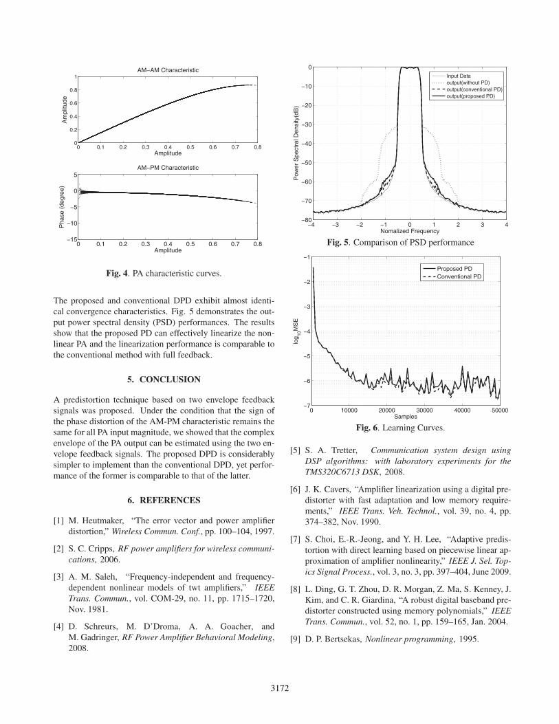
where w1,1 = 1.5, w1,2 = −0.5, w1,3 = −0.5, w1,4 =1.25, w1,5 = −0.75, w2,1 = −0.1, w2,2 = 0.1, w2,3 =0.1, w2,4 = −0.05, w2,5 = −0.05, w3,1 = 0.05, w3,2 =−0.2, w3,3 = −0.2, w3,4 = 0.05, w3,5 = 0.05, and τ1 =0, τ2 = 1, τ3 = 2. Fig. 4 shows AM-AM and AM-PM
characteristics of the RF PA model in (12). For modeling
the envelope detector, finite impulse response (FIR)-type low
pass filter is implemented. The initial value of the LMS al-
gorithm in (11) is: h = [1, 0, · · · , 0]T . The scaled diagonal
matrix μD in (11) is given by μD = diag[0.1, 1, 2, 5].Fig. 6 shows the learning curves for the mean square er-
rors (MSE), which are obtained by averaging over 100 trials.
3171
0 0.1 0.2 0.3 0.4 0.5 0.6 0.7 0.80
0.2
0.4
0.6
0.8
1
Amplitude
Am
plitu
deAM−AM Characteristic
0 0.1 0.2 0.3 0.4 0.5 0.6 0.7 0.8−15
−10
−5
0
5
Amplitude
Pha
se (
degr
ee)
AM−PM Characteristic
Fig. 4. PA characteristic curves.
The proposed and conventional DPD exhibit almost identi-
cal convergence characteristics. Fig. 5 demonstrates the out-
put power spectral density (PSD) performances. The results
show that the proposed PD can effectively linearize the non-
linear PA and the linearization performance is comparable to
the conventional method with full feedback.
5. CONCLUSION
A predistortion technique based on two envelope feedback
signals was proposed. Under the condition that the sign of
the phase distortion of the AM-PM characteristic remains the
same for all PA input magnitude, we showed that the complex
envelope of the PA output can be estimated using the two en-
velope feedback signals. The proposed DPD is considerably
simpler to implement than the conventional DPD, yet perfor-
mance of the former is comparable to that of the latter.
6. REFERENCES
[1] M. Heutmaker, “The error vector and power amplifier
distortion,” Wireless Commun. Conf., pp. 100–104, 1997.
[2] S. C. Cripps, RF power amplifiers for wireless communi-cations, 2006.
[3] A. M. Saleh, “Frequency-independent and frequency-
dependent nonlinear models of twt amplifiers,” IEEETrans. Commun., vol. COM-29, no. 11, pp. 1715–1720,
Nov. 1981.
[4] D. Schreurs, M. D’Droma, A. A. Goacher, and
M. Gadringer, RF Power Amplifier Behavioral Modeling,
2008.
−4 −3 −2 −1 0 1 2 3 4−80
−70
−60
−50
−40
−30
−20
−10
0
Nomalized Frequency
Pow
er S
pect
ral D
ensi
ty(d
B)
Input Dataoutput(without PD)output(conventional PD)output(proposed PD)
Fig. 5. Comparison of PSD performance
0 10000 20000 30000 40000 50000−7
−6
−5
−4
−3
−2
−1
Samples
log 10
MS
E
Proposed PDConventional PD
Fig. 6. Learning Curves.
[5] S. A. Tretter, Communication system design usingDSP algorithms: with laboratory experiments for theTMS320C6713 DSK, 2008.
[6] J. K. Cavers, “Amplifier linearization using a digital pre-
distorter with fast adaptation and low memory require-
ments,” IEEE Trans. Veh. Technol., vol. 39, no. 4, pp.
374–382, Nov. 1990.
[7] S. Choi, E.-R.-Jeong, and Y. H. Lee, “Adaptive predis-
tortion with direct learning based on piecewise linear ap-
proximation of amplifier nonlinearity,” IEEE J. Sel. Top-ics Signal Process., vol. 3, no. 3, pp. 397–404, June 2009.
[8] L. Ding, G. T. Zhou, D. R. Morgan, Z. Ma, S. Kenney, J.
Kim, and C. R. Giardina, “A robust digital baseband pre-
distorter constructed using memory polynomials,” IEEETrans. Commun., vol. 52, no. 1, pp. 159–165, Jan. 2004.
[9] D. P. Bertsekas, Nonlinear programming, 1995.
3172