Design and Implementation of a Microcontroller Based Forced Air Egg Incubator · 2020-02-03 ·...
146
Design and Impl Based Fo Mu DEPARTMENT OF ELE DHAKA UNIVERSITY OF lementation of a Microc Forced Air Egg Incubato uhammad Anowar Kabir ECTRICAL AND ELECTRONIC EN F ENGINEERING AND TECHNOL December 2014 controller or NGINEERING LOGY, GAZIPUR
Transcript of Design and Implementation of a Microcontroller Based Forced Air Egg Incubator · 2020-02-03 ·...

Design and Implementation of a Microcontroller Based Forced Air Egg Incubator
Muhammad Anowar Kabir
DEPARTMENT OF ELECTRICAL AND ELECTRONIC ENGINEERING
DHAKA UNIVERSITY OF ENGINEERING AND TECHNOLOGY, GAZIPUR
Design and Implementation of a Microcontroller Based Forced Air Egg Incubator
Muhammad Anowar Kabir
DEPARTMENT OF ELECTRICAL AND ELECTRONIC ENGINEERING
DHAKA UNIVERSITY OF ENGINEERING AND TECHNOLOGY, GAZIPUR
December 2014
Design and Implementation of a Microcontroller Based Forced Air Egg Incubator
DEPARTMENT OF ELECTRICAL AND ELECTRONIC ENGINEERING
DHAKA UNIVERSITY OF ENGINEERING AND TECHNOLOGY, GAZIPUR

Design and Implementation of Forced Air Egg Incubator
submitted to the Department of Electrical and Electronic Engineering, DUET in the partial fulfillment of the requirements for the award of the degree
Electr
Prof. Dr. Md. Anwarul Abedin
DEPARTMENT OF ELECTRICAL AND ELECTRONIC ENGINEERING
DHAKA UNIVERSITY OF ENGINEERING AND TECHNOLOGY, GAZIPUR
Design and Implementation of a Microcontroller Based Forced Air Egg Incubator
A project report submitted to the Department of Electrical and Electronic Engineering, DUET in the partial
fulfillment of the requirements for the award of the degree
of
Master of Engineering in
Electrical and Electronic Engineering
By
Muhammad Anowar Kabir Student No.: 102211-P
Under Supervision of
Prof. Dr. Md. Anwarul Abedin
Head, Department of EEE
DEPARTMENT OF ELECTRICAL AND ELECTRONIC ENGINEERING
UNIVERSITY OF ENGINEERING AND TECHNOLOGY, GAZIPUR
December 2014
Microcontroller Based
submitted to the Department of Electrical and Electronic Engineering, DUET in the partial fulfillment of the requirements for the award of the degree
DEPARTMENT OF ELECTRICAL AND ELECTRONIC ENGINEERING
UNIVERSITY OF ENGINEERING AND TECHNOLOGY, GAZIPUR


i
Declaration
I hereby declare that this project is my own work and has not been
submitted elsewhere for the award of any degree or diploma.
Signed: ……………………………………………………..
Date: ……………………………………………………..

ii
Acknowledgements
In this very moment, I would like to express my gratitude to the almighty Allah for
His blessing on me to complete this work successfully. I would like to extend my deepest
gratitude to all who have helped me in one way or another to finish the work at hand, this
dissertation.
I am greatly thankful to my supervisor Prof. Dr. Md. Anwarul Abedin for his
unending support throughout my M. Engineering study. For his students, he has always
taught to never forget that hard work is the only way to success. Without his continuous
monitoring, encouragement and tolerance to numerous mishaps, I could not have successfully
completed this work.
I am grateful to Prof Dr. Md. Shahid Ullah Head, EEE Department Islamic University
of Technology (IUT) for providing the facilities and advice in carrying out the study, and the
encouragement for the completion of this project. I am grateful to Jose Neuca, Incubator Repair and Fabrication, 12897 Antipas,
Mayondon Los Banos Laguna, Phylippins-4030 was always helpful and share his practical
experience of Egg Incubator and offered continuous support for my project works. Special
thanks and appreciations are due to the Faculty of Animal Husbandry, Bangladesh Agricultural
University, Mymensingh - 2202, Bangladesh, Poultry Rearing and Farming Department,
Technical School and College, Gazipur and poultry farmers in the study areas who provided the
relevant information for preparing this thesis. I want to thank all staff of my Indigenous
Technology Research and Development Laboratory, M A Aziz Peace Institute of
Technology, Gazipur for supporting me in building the hardware and test incubation
processes.
My deepest gratitude goes to my wife for her unflagging love and support throughout
my life. I would like to acknowledge the sacrifice and love of my parents. My father Md.
Abdul Aziz very helpful in fabricating and constructing the casing and egg turning system.
At last, I would like to thank to all the members of Department of Electrical and
Electronic Engineering Dhaka University of Engineering and Technology, Gazipur whose
love and affection made my course a memorable. I cannot forget the memories of each of the
moments during my study at DUET.
iii
Abstract
Incubation of eggs is an old process, but the act of incubation using the artificial
method is developing day by day. Creating an efficient incubator at a moderate and
affordable price is challenging because egg embryos (the developing chick in an egg) are
delicate, even a slight change of temperature, humidity and ventilation can affect the timing
of the hatchings, likewise a rough turning of the egg can kill the embryo. Commercial and
imported incubators available in the market are far greater in size than requirement of small
villages and costly. To acquire the goal of “One Home is One Farm”, it is present demand to
design low cost full function automatic high efficiency domestic incubator and to modernize
present mini-hatchery technology. The purpose of this project is to design, construct and
implement microcontroller based low cost universal domestic incubator which is able to
incubate different types of eggs and to modernize present mini-hatchery technology using
locally available material and resource to achieve a cost effective design.
The control unit is designed for monitoring and control the main incubation
parameters, like: temperature, humidity, ventilation (to control oxygen and carbon dioxide
level and air velocity), position of eggs and turning of eggs fulfills effective way as natural
incubation by using sensors and associated devices.
User friendly Human Machine Interfacing Menu Program (HMIMP) is implemented.
A twenty character by four lines liquid crystal display (LCD) allows the user to visualize
settings during configuration and the system status during operation. The implemented
control unit was tested in the laboratory as well as in the field.
The incubator combines the Setter and Hatcher together. The incubator can incubate
up to 120 eggs at a time. The incubator takes about 22 minutes to reach its Set Temperature
(from 22°C to 37.5°C). At that time it consumes 207 Watts. It consumes 69 Watts or
less after reaching its Set Temperature. It consumes approximately 35 kWh (kilowatt-hour)
electric powers for chick (21 days) incubation. It has automatic egg turning system, and alarm
on the high and low temperature and humidity.
It has advanced auto saving data log facility in excel which is very useful and realistic
for getting right prediction from output result to improve incubator operation for optimum
performance. This incubator can be used as educational egg incubator for Agricultural
School, college, institute, university and other research institutes and laboratory.

Contents
Declaration i
Acknowledgements ii
Abstract iii
List of Figures vii
List of Tables xi
1 Introduction 1 1.1 Background and Justification 1
1.2 Problem Statement 7
1.3 Aims and Objectives 8
1.4 Expected Benefits 9
1.5 Project Report Layout 10
2 Egg Incubation and Embryology 12 2.1 Introduction 12
2.2 Natural Incubation 12
2.3 Artificial Incubation 15
2.4 Egg Embryology 16
2.5 Important Incubation Factors Required to Maintain for Designing a
Successful Egg Incubator
17
2.5.1 Temperature 18
2.5.2 Eggs Position and Turning of eggs 24
2.5.3 Humidity 27
2.5.4 Ventilation and Oxygen Availability 34
2.5.5 Sanitation 35

Contents
v
2.6 Length of Incubation 37
2.7 Monitoring of Eggs and the Incubator 40
2.8 Different Types of Egg Incubators 41
2.9 Size of Incubator 42
2.10 Incubator Construction and Function 43
2.10.1 Still Air Incubators 43
2.10.2 Forced-Air Draft Incubators 44
3 Design of a Microcontroller Based Forced Air Egg Incubator 46 3.1 Introduction 46
3.2 Incubator Design Considerations and Implementation 46
3.3 Mechanical Structure Design of the Incubator 48
3.3.1 Incubator Casing 48
3.3.2 Heating Element and Heating Cable 52
3.3.3 Egg Setter Tray 52
3.3.4 Tray Supports 52
3.3.5 Egg Tray Turning Mechanism 53
3.3.6 Egg Hatcher Tray 54
3.3.7 Circulating Fan 54
3.3.8 Ventilation System 54
3.3.9 Water Supply and Water Pans 54
3.4 Embedded System Design of the Incubator 55
3.4.1 Electronic Hardware Design 56
3.4.1.1 The Microcontroller Unit (MCU) 56
3.4.1.2 The Sensor Unit 58
3.4.1.3 The Real Time Clock (RTC) Unit 69
3.4.1.4 The User Interface 72
3.4.1.5 Auto Saving Data Logging in MS Excel 75
3.4.1.6 The Driver Unit 76
3.4.1.7 The Power Supply Unit 78
3.4.1.8 Overall Circuit Diagram of the Incubator 80
3.4.1.9 IR Remote Control for Egg Turning System 82

Contents
vi
3.4.2 Software Development 84
3.4.2.1 Main Program Flow of the System 84
3.4.2.2 Block Diagram for Menu Program 85
3.4.2.3 DS18B20 Temperature Sensors Read and Process Sub-program 87
3.4.2.4 LM35 Temperature Sensors Read and Process Sub-program 87
3.4.2.5 Humidity Sensors Read and Process Sub-Program 87
3.4.2.6 Temperature Control Sub-Program 87
3.4.2.7 Humidity Control Sub-Program 90
3.4.2.8 Egg Turning Control Sub-Program 90
3.4.2.9 Ventilation Control and Alarm System Sub-Program 90
3.4.2.10 IR Remote Control Transmitter 91
3.4.2.11 IR Remote Control Receiver 91
3.4.2.12 Program Coding 91
3.4.2.13 Chips Programming 91
3.5 PCB Design, Fabrication and Electrical Wiring 92
3.5.1 MBFAEIC Motherboard 92
3.5.2 PC Interface Card 93
3.5.3 Relay Driver Card 94
3.5.4 Fabrication MBFAEI Controller Unit 95
3.5.5 Electrical Wiring 96
4 Test Hatching and Performance Analysis 98 4.1 Introduction 98
4.2 Incubation of Eggs in Incubator (MBFAEI) 100
4.3 The Incubator (MBFAEI) Hatching Tests and Performance Analysis 112
5 Conclusion and Recommendation 116 5.1 Conclusion 116
5.2 Recommendation 118
References 119
Appendices 124
List of Figures
Fig. No. Caption Page
1.1 Egyptian Incubator …………...……………………..………………..…….. 03
1.2 A Chinese Incubator (From the Journal “The Baby Chick”) ………….……. 04
1.3 Rice Husk Method, Mini-hatchery PKSF/IFAD ………………………….. 05
1.4
Sand Method, Mini-hatchery PKSF/IFAD …………………………….…... 06
2.1 Birds Nest Engineering for Proper Incubating Environment ……………… 14
2.2 Heat Production of Incubating Eggs ……………………………………… 17
2.3 Five Incubation Temperature Zones for Chicken Eggs …………………… 19
2.4 The Proper Orientation of the Egg During Incubation ………………..…… 24
2.5 Egg Tray Turning Method ……………………………………………… 26
2.6 Optimum Weight Loss of Eggs during Incubation ...……………………… 29
2.7 The Growth of Air Cell during the Incubation …….……………………… 32
2.8 The Average Actual Weights of Incubating Eggs against the Ideal Weight
Loss Line …………………………………………………………………...
33
2.9 Candler (a) Candler using Light Bulb, (b) Candler using Torch ………… 41
2.10 Still-air Egg Incubator ………………………………………………… 43
2.11
Forced-air Draft Incubator ………………………………………………….. 44
3.1 Microcontroller Based Forced Air Egg Incubator Implementation Flow Chart. 47
3.2 Microcontroller Based Forced Air Egg Incubator Prototype ……………….. 49
3.3 Typical View of the Incubator Casing During Construction Process ………. 50
3.4 Insulation Layer in Between Plywood ……………………………………… 51
3.5 Typical View of Door with Glass Window …………………………………. 51
3.6 Egg Tray ……………………………………………………………………. 52

List of Figures
viii
Fig. No. Caption Page
3.7 Tray Supports ………………………………………………………………. 53
3.8 Egg Tray Turning Mechanism ……………………………………………… 53
3.9 Microcontroller Based Forced Air Egg Incubator Controller Block Diagram 55
3.10 PIC16F877A Microcontroller (a) Physical Layout (b) Pin Configuration .. 57
3.11 PIC16F877A Internal Block Diagram ……………………………………… 59
3.12 LM35Voltage Output Temperature Sensor ………………………………… 61
3.13 DS18B20 Digital Output Temperature Sensors ………………………….. 62
3.14 DS18B20 Detail Pin Description …………………………………………… 62
3.15 DS18B20 Block Diagram …………………………………………………… 63
3.16 DS18B20 Typical Connection ……………………………………………. 63
3.17 Physical Sensor Connection ……………………………………………… 64
3.18 DS18B20 Memory Map …………………………………………………… 64
3.19 Temperature/Data Relationship …………………………………………… 65
3.20 DS18B20 Initialization Timing …………………………………………… 65
3.21 HSM20G Humidity Sensor (a) Front View , (b) Back View ……………… 67
3.22 Relative Humidity Response of HSM-20G ……………………….………... 67
3.23 Physical Sensor Connection (HSM20G) ………………………………… 68
3.24 DS1302 Pin Diagram ………………………………………………………. 69
3.25 Wiring Diagram for the DS1302 …………………………………………… 70
3.26 Typical PC Board Layout for Crystal …………………………………….. 71
3.27 Register Address / Definition ……………………………………………….. 72
3.28 Human Machine Interfacing Push Buttons Control Circuitry ………………. 73
3.29 The Switch Contacts Bounce ………………………………………………. 74
3.30 The Ideal Waveform of Switch Contact ……………………………………. 74
3.31 Signal as it Leaves the PIC Pin (The PIC Side of the MAX232) ………… 76
3.32 Signal on an RS232 Line (The PC Side of the MAX232) ………………… 76
3.33 RS232 Data Logger Circuit …………………………………………………. 76
3.34 Buzzer Circuit ……………………………………………………………… 77
3.35 Interfacing Relay with Microcontroller ………………………………….… 77
3.36 Interfacing Relay with Microcontroller using Opto-Isolator ……………… 78
3.37 Independent +5V Regulated Power Supply ……………………………… 78
List of Figures
ix
Fig. No. Caption Page
3.38 Independent +12V Regulated Power Supply ...…………………………… 79
3.39 Overall Circuitry of the MCBFAEI (Part-1) ……………………………… 80
3.40 Overall Circuitry of the MCBFAEI (Part-2) ……………………………… 81
3.41 IR Remote Control Transmitter and Receiver System ……………………… 82
3.42 Modulation of SIRC Protocol ………………………….…………………… 82
3.43 SIRC Protocol Signal Pattern ……………………………………………… 83
3.44 Main Program Flow of the Incubator ………………………………………. 84
3.45 Human Machine Interfacing Menu Program (HMIMP) Operation (Part 1) .. 85
3.46 Human Machine Interfacing Menu Program (HMIMP) Operation (Part 2) .. 86
3.47 Temperature Control Sub-Program ………………………………………… 89
3.48 Humidity Control Sub-Program …………………………………………… 90
3.49 MBFAEIC Motherboard (Bottom Copper View) ………………………….. 92
3.50 MBFAEIC Motherboard (Top View) …………………………………….… 92
3.51 MBFAEIC Motherboard (3D Visualization using ARES Professional) ……. 93
3.52 PC Interface Card (Top View, Bottom Copper View and 3D visualization) 93
3.53 Relay Driver Card (Top View and Bottom Copper View) ………………… 94
3.54 Relay Driver Card (3D Visualization) …………………………………….. 94
3.55 Relay Driver Card with Opto-Isolator (Top View, Bottom Copper View and
3D Visualization) ……………………………………………………………
94
3.56 MBFAEIC Housing of the PCB Cards …………………………………….. 95
3.57 MBFAEI Controller in Operation (Data Logging) …………………………. 95
3.58 Electrical Wiring of Egg Turning Motor, Ventilation and Humidity Control
System ……………………………………………………………………...
96
3.59
Electrical Wiring of Four Heating Elements ……………………………… 97
4.1 The Incubators Normal Run and Operation Mode Display Information ….. 98
4.2 Fumigation of Hatching Eggs …………………………………….………… 100
4.3 Egg Storage ………………………………………………………………… 101
4.4 Loading of Hatching Eggs to Setter Tray …………………………………… 102
4.5 Eggs are Transferred to Hatcher Tray ……………………………………. 109
4.6 Successfully Hatched DOCs (Day Old Chicks) ………………………… 110
4.7 Steps Involved in Successfully Egg Incubation Operations ………………… 111
4.8 The Incubator (MBFAEI) Hatched Chicks-1 ……………………………… 112
List of Figures
x
Fig. No. Caption Page
4.9 The Incubator (MBFAEI) Hatched Ducks …………..…………………… 112
4.10 The Incubator (MBFAEI) Hatched Chicks-2 ……………………………… 113
4.11 The Incubator (MBFAEI) Hatched (Multistage) Coturnix Quail ………… 113
4.12 The Incubator (MBFAEI) Hatched (Multistage) Chicks-3 ………………… 114
4.13 Coturnix Quail and Indigenous Chicks Intensive Rearing ………………….. 114
4.14 Implemented Incubators ………………………………………………….. 115

xi
List of Tables
Fig. No. Caption Page
2.1 The Incubation Period and Incubator Operation for Common Domestic Birds (Part-1) 38
2.2 The Incubation Period And Incubator Operation For Common Domestic Birds (Part-2) 39
2.3
The Advantages and Disadvantages the Still-Air and the Forced-Air Incubator 45
3.1 Internal and External Dimensions of the Incubator ……………………….. 49
3.2 Egg Setter Tray Dimension ………………………………………………… 52
3.3 Relative Humidity Verses Output Voltage Relation ………………………. 68

Chapter 1
Introduction
1.1 Background and Justification
Bangladesh is the biggest delta landscape in the world with a large human and
natural resources [1]. Over 74% of the total population lives in rural areas and they are
dependent on agriculture [2] for their livelihood. Agriculture is one of the most important
segments in Bangladesh and growth and sustainability of agricultural production are
prerequisite for attaining the rate of overall growth of the economy. Agriculture sector
plays an important role in the overall economic development of Bangladesh and it is
regarded as the lifeline of Bangladesh economy. It is also an important social sector
concerned with some issues like food and nutritional security, income generation, and
poverty reduction. The increasing ratio of eggs, meat and milk production is considered as
a good sign and a step for the improvement of our nation’s health nutrition. The
agriculture sector in Bangladesh is gradually diversifying in favor of high-value
commodities, mainly fruits, vegetables, livestock, poultry and fish products. After
readymade garment sector, poultry farming has turned out to be promising dynamic
enterprise with enormous potential for rapid poverty reduction in Bangladesh. Poultry
enterprise is also most vital due to its contributions to national economy in sphere of
generation of local income-employment creation and improving the nutrition level of third
world country like Bangladesh. The term “poultry” applies to a rather wide variety of birds
of several species. Men’s can get financial benefit from those kinds of birds and the birds
reproduce with the care of man is called poultry. Chickens, ducks, geese, Guinea fowl,
pigeon, turkeys etc. are generally considered as poultry birds [3-4]. Poultry industry is one
of the major among livestock sub-sectors that committed to supply cheap sources of good

Chapter 1. Introduction
2
quality nutritious animal protein to the nation. Poultry meat contributes approximately
37% of the total animal protein in our country [5].
People in our country raise poultry mainly with a view to get meat and egg to
fulfill their day to day consumption. Poultry meat and egg holds an important position in
our daily diet. The per capita consumption of all meat is 14.67 Kg and that of egg is 31
numbers as against the requirements of 56 Kg meat and 365 eggs, respectively [6].
Approximately 70% people in our country are suffering from malnutrition and 81%
families don’t get calories according to their needs [3-4]. Malnutrition is caused for the
lacking of protein. The worst victims of malnutrition of this country are usually the
children and the women. A large portion of children are suffered from anemia and
underweight for lacking of nutrition. Today the concept of human nutrition has taken a
new dimension. The emphasis has been given on high protein and low calorie diet, as
protein plays a vital role in the balanced and health growth of human being. Poultry is a
great source of protein by providing eggs and meat. It provides palatability and is a good
source of essential amino acids, vitamins and minerals. Poultry meat shared second
position of the meat production. In this circumstance, poultry appears to be a good way of
meeting the protein gap by providing eggs and meat with low cost. The price of poultry
meat is comparatively lower than other livestock like beef, muttons meat and others.
With the unfavorable land-man ratio accompanied by unexpectedly high growth
rate of population, the number of disguised unemployed manpower in the country is
increasing day by day. About 31.5% people live under poverty line in our country [7].
Profitable intensive poultry rearing can play a vital role in Bangladesh because the
landless people and owner of low land in our country can easily rear intensive poultry
through of the limitation of land scarcity. It is difficult to set up commercial dairy or goat
farm in a large scale to fulfill the protein demand.
Egg incubator plays an important role in the overall poultry production system
especially during the day old chick development. In Bangladesh, poultry production is a
lucrative business but lack of commercially owned hatchery machines hinder the
expansion and make poultry products for instance day old chicks costly more especially in
the remote village area of Bangladesh. A part of the disguised unemployed people can be
employed with the family poultry development and production business by producing their
Chapter 1. Introduction
3
own DOC (Day Old Chick) in their own egg incubator, to reduce the present DOC and
hatching egg problem.
An egg incubator is a piece of equipment that creates the perfect conditions for an
egg to incubate. Successful incubation environment depends on maintaining favorable
conditions for hatching fertile eggs. Temperature, Humidity, Ventilation (for oxygen,
carbon dioxide and the internal pH) and Turning frequency during the incubation period
markedly affect the hatchability of fertile eggs and chick quality [8].
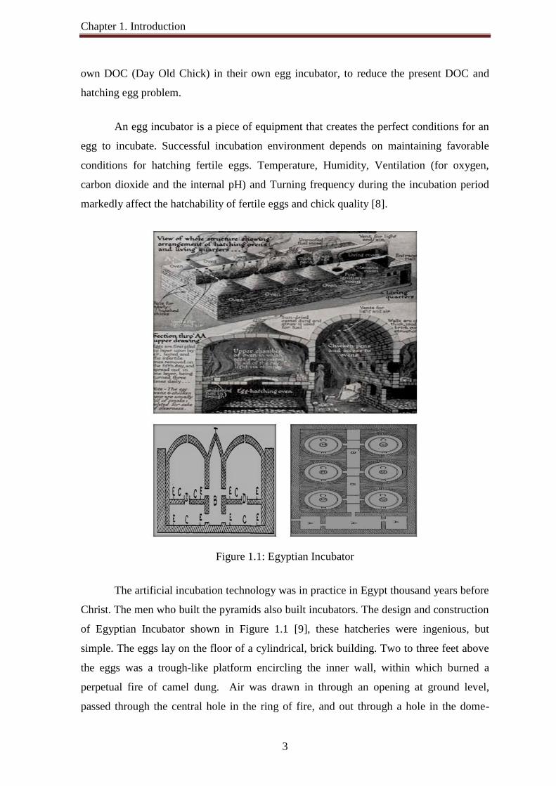
Figure 1.1: Egyptian Incubator
The artificial incubation technology was in practice in Egypt thousand years before
Christ. The men who built the pyramids also built incubators. The design and construction
of Egyptian Incubator shown in Figure 1.1 [9], these hatcheries were ingenious, but
simple. The eggs lay on the floor of a cylindrical, brick building. Two to three feet above
the eggs was a trough-like platform encircling the inner wall, within which burned a
perpetual fire of camel dung. Air was drawn in through an opening at ground level,
passed through the central hole in the ring of fire, and out through a hole in the dome-

Chapter 1. Introduction
shaped roof. Double rows of these incubating ovens faced on to a central corridor.
Openings in the roof and ends of this corridor admitted light and ventilation. Th
temperature of the eggs was measured by placing them against the eye
by stoking or raking the fires. Humidity requirements and air cell size were judged by the
sound made by rolling two eggs together in one hand.
The Egyptians did not, however, have a monopoly on egg hatching. Their Chinese
counterparts had developed two very successful methods by at least 1,000 B.C. The
and simplest, used the heat of rotting manure. The eggs were placed in a mixture of
chopped straw and rice hulls on top of the manure; it appears to have been moderately
successful. The second method, more widely used and still functional today, was just as
ingenious as the Egyptian hatchery. The basic structure was again a cylindrical building,
but the fire was on the floor, with the eggs contained in an inverted cone above it, partially
filled with ashes. Placed on the ashes were egg baskets made of woven straw. The eggs
were contained in muslin bags, the whole being covered in an insulating layer of rice hu
A straw thatch roof, shaped like the traditional coolie's hat, completed the insulation, and
kept out the rain. The Figure 1.2 shows a Chinese incubator found in the journal The Baby
Chick.
Figure 1.2: A Chinese I
Every seven days a fresh bag of eggs was added to each basket, and the bags were
continually moved about to turn the eggs. After the first three weeks of the hatching
season, the fire was allowed to go out; the self
going. They had also developed the art of candling, for clear eggs were removed on the
third day and sold for normal consumption.
4
shaped roof. Double rows of these incubating ovens faced on to a central corridor.
Openings in the roof and ends of this corridor admitted light and ventilation. Th
temperature of the eggs was measured by placing them against the eye-
by stoking or raking the fires. Humidity requirements and air cell size were judged by the
sound made by rolling two eggs together in one hand.
not, however, have a monopoly on egg hatching. Their Chinese
counterparts had developed two very successful methods by at least 1,000 B.C. The
and simplest, used the heat of rotting manure. The eggs were placed in a mixture of
e hulls on top of the manure; it appears to have been moderately
method, more widely used and still functional today, was just as
ingenious as the Egyptian hatchery. The basic structure was again a cylindrical building,
was on the floor, with the eggs contained in an inverted cone above it, partially
filled with ashes. Placed on the ashes were egg baskets made of woven straw. The eggs
were contained in muslin bags, the whole being covered in an insulating layer of rice hu
A straw thatch roof, shaped like the traditional coolie's hat, completed the insulation, and
kept out the rain. The Figure 1.2 shows a Chinese incubator found in the journal The Baby
A Chinese Incubator (From the Journal “The B
Every seven days a fresh bag of eggs was added to each basket, and the bags were
continually moved about to turn the eggs. After the first three weeks of the hatching
season, the fire was allowed to go out; the self-generative heat of the eggs
going. They had also developed the art of candling, for clear eggs were removed on the
third day and sold for normal consumption.
shaped roof. Double rows of these incubating ovens faced on to a central corridor.
Openings in the roof and ends of this corridor admitted light and ventilation. The
-lids, and controlled
by stoking or raking the fires. Humidity requirements and air cell size were judged by the
not, however, have a monopoly on egg hatching. Their Chinese
counterparts had developed two very successful methods by at least 1,000 B.C. The first,
and simplest, used the heat of rotting manure. The eggs were placed in a mixture of
e hulls on top of the manure; it appears to have been moderately
method, more widely used and still functional today, was just as
ingenious as the Egyptian hatchery. The basic structure was again a cylindrical building,
was on the floor, with the eggs contained in an inverted cone above it, partially
filled with ashes. Placed on the ashes were egg baskets made of woven straw. The eggs
were contained in muslin bags, the whole being covered in an insulating layer of rice hulls.
A straw thatch roof, shaped like the traditional coolie's hat, completed the insulation, and
kept out the rain. The Figure 1.2 shows a Chinese incubator found in the journal The Baby
The Baby Chick”)
Every seven days a fresh bag of eggs was added to each basket, and the bags were
continually moved about to turn the eggs. After the first three weeks of the hatching
generative heat of the eggs kept the process
going. They had also developed the art of candling, for clear eggs were removed on the

Chapter 1. Introduction
5
The Greeks were not to be outdone, for Aristotle described in detail a method using
rotting manure in 400 B.C. Several records exist of high-born Roman ladies foretelling the
sex of their offspring by hatching an egg tucked under their breasts. Numerous
descriptions of methods using the heat of the human body are recorded throughout history
and from all over the world. Philippine islanders paid their servants to lie on eggs. The
eggs were laid between rows of sticks on a bed of ashes, and both servant and eggs were
covered with blankets. South African farmers employed native girls to hatch ostrich eggs
with body heat, when the feathers of these birds were in terrific demand. Over the year’s
incubators have been refined and developed so they are almost completely automatic.
Mini-hatcheries have been in use in Bangladesh since the 1970s. In 1992, BRAC
has taken up a program on Rice Husk Incubator in various parts of Bangladesh. It is
named as “Rice husk method of incubation” because the rice husk is used as the main
ingredient (element) to insulate against heat loss [10]. However, the system was not
widely adopted, largely because of poor management of fertile eggs in the supply chain.
The Palli Karma Sahayak Foundation (PKSF) has led the implementation of the IFAD
funded Microfinance and Technical Support Project (MFTSP) across 97 sub-districts in
southern and north-eastern Bangladesh, in partnership with other NGOs to adopting a
mini-hatchery techniques as an income generating activities of their beneficiaries. Mini-
hatchery becomes popular among the rural peoples of Kishoregonj, Hobigonj and Sylhet
district of Bangladesh for its low installation and management cost and high benefit.
Rural peoples of various part of Bangladesh are using three types of mini-
hatcheries like Rice Husk method, Rice Husk & Quilt method and Sand method, which are
modified Chinese incubator. For rice husk incubation technique, the items needed are:
incubation room, incubation box, incubation cylinder, hatching bed, petrol lamp,
thermometer, bamboo tray, color cloth, candling box and rice husk. For sand incubation
technique, the items needed are: incubation box, tray (made with net), thermometer, lamp
(hurricane), water pot, and sand.
In Rice Husk Incubation Technique in shown Figure 1.3 [11], the bamboo made
incubation box and two (or three) cylinders (which are also bamboo made) are needed to
be set up in a dark room (incubation room), possibly well insulated. The cylinders are
placed in a central point. Then the incubation chamber should be filled up with rice husk.

Chapter 1. Introduction
6
A petrol lamp (Hurricane) should always be kept in one cylinder alternately during the
entire hatching period to keep the chamber warm up to 98-100° F or 37-38°C.
(a) Incubation cylinder (Bamboo) placed inside the rise husk filled Incubation box, along with the thermo-meter Incubation cylinder heated with kerosene lamp.
(b) A poultry rearer heating the eggs on a bamboo strainer to putting them in the Incubation cylinders.
(c) An incubation box housing three incubation cylinders.
Figure 1.3: Rice Husk Method, Mini-hatchery PKSF/IFAD In Sand Incubation Technique shown in Figure 1.4 [11], an insulated box like an
almirah (cupboard) is made up of wooden or particle board composed of outlet for gas
emission and ventilation to control temperature. Inside the box there are 3 to 5 gunny sac
trays supported by the wire net which are used as egg setting and hatching trays as well.
At the bottom of the incubator there are two kerosene based hurricane lamps placed as a
source of heat and the bowl with water to maintain the humidity. The lower-most tray
contains sand to be heated and give a distributed uniform temperature (98-100° F or 37-
38°C) within the surrounding area of the incubator.
(a) Diagram of the sand-based incubator and its internal arrangement
(b) Four-shelved incubating box for the sand-type mini hatchery
(c) Front doors of the incubi-tion box are covered with rice-husk filled gunny bags
Figure 1.4: Sand Method, Mini-hatchery PKSF/IFAD

Chapter 1. Introduction
7
A person may easily get a net benefit of around 5,000 to 10,000 taka per month
from a hatchery of 1000 eggs. This technology has been changed socioeconomic status of
many people in the rural areas. Many educated unemployed person are also engaged
themselves in this sector and earning their livelihood, which is encouraging many other
people to engage themselves in this sector.
1.2 Problem Statement
Many people of our country are very much interested in adopting a mini-hatchery
technology, but the main problem is lack of proper technical and financial support. The
PKSF was not very successful in their projects largely on account of poor management of
the supply chain of hatching eggs, poor quality of eggs and the high labor inputs required.
Due to the lack of technology and proper technical knowledge, they could not maintain
proper temperature of the hatchery and the hatching percentage may reduce (below 50%)
or completely stop during the winter period from mid November till February, when
temperatures fall to a low of 20° C [12]. Thus, the hatcheries remain closed for 2-3 months
in winter.
The problems of early hatching, late hatching, pipped eggs with no hatching, blood
rings and dead embryos (the developing chick in an egg is called an embryo) at early stage
of egg embryo development are common problem in these analogues (manual) egg
incubators. These symptoms are a commonly caused by incorrect incubation
measurements. For example, early hatching is caused by high incubation temperature
while late hatching is a result of low temperature. Pipped eggs without hatching that is,
cannot escape from the egg shell are caused by two factors, namely; improper ventilation
and insufficient moisture (low humidity). Blood rings in the eggs are caused by inaccurate
incubation temperature due to manual temperature control; dead embryos at an early stage
are caused by improper egg turnings (needed three times a day) and ventilation [13].
Very few farmers locally manufacture box type egg incubators for their own DOC
production but in those system there are improper control of temperature, humidity, egg
turnings and ventilation. They are not user-friendly and easy to maintain. Commercial and
imported incubators available in the market are far greater in size than requirement of
small villages and highly costly.
Chapter 1. Introduction
8
Incubation and hatching of eggs is an old process, but the act of incubation using
the artificial method is developing day by day. Creating an efficient incubator at a
moderate and affordable price is challenging because egg embryos are delicate even a
slight change of temperature, humidity and ventilation can affect the timing of the
hatchings, likewise a rough turning of the egg can kill the embryo. This situation has
received the attention of researchers, academicians and some non-governmental
organizations to improve the DOC production and to improve the economic condition of
the rural people through poultry rearing.
1.3 Aims and Objectives The aims and objectives of this project are:
i. To design and construct a low cost incubator using microcontroller, IC based
sensors and other materials those are readily available in the local market.
ii. To design an egg incubator that is able to incubate different types of eggs like hen,
duck, quail etc. with minimum external supervision.
iii. To design user friendly Human Machine Interfacing Menu Program (HMIMP) to
adjust and set the different incubation conditions necessary for each type of eggs.
iv. To design an incubator with data logging facility which will help different
Institution’s research laboratories to get a right prediction from output result.
v. To design an incubator to serve a dual purposes i.e. combination of Setter and
Hatcher in a single unit.
1.4 Expected Benefits
In this project, microcontroller based forced air egg incubator is designed,
implemented and tested for multi-stage incubation; the incubator contains different eggs
(Duck, hen and Quail) and of different embryonic ages. The expected benefits of this
project works are:
The construction of the incubator use locally available cheap materials, so its
manufacturing cost is low. It’s all accessories are locally available; maintenance is
easy and low cost. It consumes less power than other egg incubators available in the
market; it can also be operated with alternative source of energy.

Chapter 1. Introduction
9
Present capacities of the incubators are 120 and 400 eggs using same control unit,
same control unit can be use up to 2000 eggs.
Its controller also can help to modernize present mini-hatchery techniques.
By changing the settings any kind of egg (i.e. hen, duck, quail etc.) can be hatched.
It made as user-friendly, portable and easy to maintain, no special skills required to
operate it. It requires minimum external supervision or control that makes it relatively affordable
to the average physically semi-disabled people and poor farmer dwelling in a rural
area.
It is a full function automatic incubator but comparatively very cheap than others
(approximate cost of control unit about Tk. 2000 to 2200 and casing of incubator about
Tk. 1000 to 3000 depending on size and materials used).
A part of the disguised unemployed people can be employed with the family poultry
development and production business by producing their own DOC (Day Old Chick)
in their own egg incubator.
It will play an important role in the day old chick development in the remote village
area in Bangladesh. This egg incubator will save time for farmers, increase their production and hence their
income.
It will help to acquire the goal of “One Home is One Farm” and increase the production of chicks and protein intake in Bangladesh.
Its advance auto saving data log facility in excel is very useful and realistic for getting
right prediction from output result to improve incubator operation for optimum
performance.
It can be used in Agriculture University, Research Institute, College and School for
their (egg embryo) research and laboratory works.

Chapter 1. Introduction
10
1.5 Project Report Layout This report is combination of four chapters that contain the Introduction,
Incubation and Egg embryology, Microcontroller based forced air egg incubator and the
last chapter is a Conclusion and Recommendation of the project.
Chapter 1 introduces the research topic and sets the direction in which the thesis
will proceed. The Background and Justification, Problem statement, Aims and Objectives,
Expected Benefits of the project are explained. The concept of the project and the overall
overview of the project are also discussed in this chapter.
Chapter 2 focuses on the natural and artificial egg incubation process, egg
embryology, important incubation factors required to maintain, to design a successful egg
incubator and various types of egg incubator.
The explanation about Microcontroller Based Forced Air Egg Incubator
(MBFAEI) project is given in Chapter 3.
The project designs, developments and implementations consist of three main parts
which are incubators mechanical structure design, embedded system design (hardware
design and software design) and test hatching for troubleshooting and upgrading the
system.
In mechanical structure design, it is about the development of the case/cabinet of
incubator, egg turning system and ventilation system. This section also, discussed the
construction and assembling procedure in detail with dimension.
In Embedded system design, it is about the development of the software, interface
circuit and hardware design. The design of this system includes two parts. These are the
hardware and software design. For proper functionality of the system, these two parts
adjust to agree with each other.
The hardware unit consists of the following sub-unit: the microcontroller unit, the
sensor unit, the real time clock calendar unit, the user interface and display unit, the auto
saving data logging in MS excel unit, the current driver unit, the actuator unit and the
power supply unit.
Chapter 1. Introduction
11
The control program for the microcontroller was written in Basic language for
code economy and speed reasons. The controller of the egg incubator development to
satisfy the incubation factors during incubation process automatically.
Chapter 4 focuses on test hatching and performance analysis of the designed
incubator. Each stage of the embryonic development and the results obtained during
incubation are also described here.
In Chapter 5, the conclusions and recommendation of the project are presented.
Chapter 2
Egg Incubation and Embryology
2.1 Introduction
Incubation refers to the process by which certain oviparous (egg-laying) animals
hatch their eggs, and to the development of the embryo within the egg. Most female birds
will become broody and sit on and hatch the clutch of eggs (generally 10-12) they have
just laid. The act of sitting on the eggs to incubate them is called brooding. The action or
behavioral tendency to sit on a clutch of eggs is also called broody, and most egg laying
breeds of chicken have had this behavior selectively bred out of them to increase
production. The most vital factor of incubation is the constant temperature required for its
development over a specific period. The more nearly the artificial method of incubation
can copy the natural one, the more successful will be the results. In this project, at first the
conditions of the natural process is observed and these are implemented in the artificial
method.
2.2 Natural Incubation
When a hen becomes broody, the arteries (blood vessel) and veins under the body
become more highly charged with blood and cover the abdomen with a warm network,
which, being pressed against the eggs, keep the latter at a temperature approximating that
of the fowl’s body. During the incubation period she sits on her eggs she frequently turns

Chapter 2. Egg Incubation and Embryology
13
them in the nest for re-arranging them to her own comfort and at the same time fulfill an
absolutely necessary condition for the successful development of the embryo. In settling
down to her eggs, after being off for a time, she generally performs the operation with a
wriggling motion, and in so doing separates the eggs slightly and partly surrounds them
with her downy feathers, a small portion only of each egg coming in contact with her
body. As incubation advances, the small end of each egg has a tendency to turn towards
the middle of the nest, and the broader ends to become slightly elevated and the enlarging
air space in the broad end causing the narrow end to be the heaviest. The number of time a
good sitter leaves her nest, and the length of time she will stay away, depends on the
weather, the degree of fertility in the eggs, and the stage of incubation. In warm weather
this will be of more frequent and of longer duration than in cold weather. She may
sometimes be noticed, when the weather is hot, to rise in the nest and shake out her
feathers as if to cool herself and the eggs. The same remark applies, even in cooler
weather, when the eggs are well fertilized with strong germs at an advanced stage, when
the animal heat in the eggs themselves is great.
In natural incubation heat is applied to the eggs by actual contact with the
incubating body, the body temperature of the sitter diminishes a little as incubation
advances, the fowl loses fat which brings the rich network of blood-vessels in the
abdomen more closely in contact with the eggs. In addition to direct contact, warmth is
applied by the diffusion of heat downwards by the feathers which partially fill the spaces
between the eggs and round the outside of the nest. Cool fresh air comes in under the eggs
and close to the bottom of the nest, gradually ascends to the heat-generating body and
becomes heated, but instead of passing out on the tops of the eggs only its exit laterally is
resisted and retarded by the downy fluff and feathers, which conduct and diffuse the heat
downwards as well as outwards, and hold suspended among them a large volume of warm
moist air, any rapid movement of which being impossible.
Moreover, the outgoing warm air meets and imports most of its heat to the
incoming cool air, so that in the gradual replacement of the volume of air around the eggs
little heat is lost. In addition to this, the earth is a poor conductor, and the heat, instead of
being absorbed, is largely radiated back to the under surfaces of the eggs. Although the
white and yolk of the egg are bad conductors, the shell is an extremely good conductor of
heat, and this property greatly assists in more evenly distributing the warmth to all parts of
Chapter 2. Egg Incubation and Embryology
14
the egg. The development of the vascular system also adds another important aid to the
conveyance and uniform distribution of heat from the upper to the under surface, and from
the outside to the inside of the egg. Birds are capable of grand engineering feats.
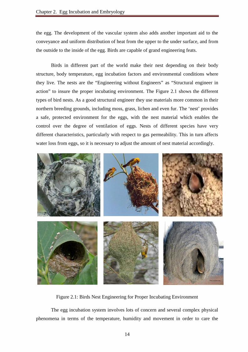
Birds in different part of the world make their nest depending on their body
structure, body temperature, egg incubation factors and environmental conditions where
they live. The nests are the “Engineering without Engineers” as “Structural engineer in
action” to insure the proper incubating environment. The Figure 2.1 shows the different
types of bird nests. As a good structural engineer they use materials more common in their
northern breeding grounds, including moss, grass, lichen and even fur. The ‘nest’ provides
a safe, protected environment for the eggs, with the nest material which enables the
control over the degree of ventilation of eggs. Nests of different species have very
different characteristics, particularly with respect to gas permeability. This in turn affects
water loss from eggs, so it is necessary to adjust the amount of nest material accordingly.
Figure 2.1: Birds Nest Engineering for Proper Incubating Environment
The egg incubation system involves lots of concern and several complex physical
phenomena in terms of the temperature, humidity and movement in order to care the

Chapter 2. Egg Incubation and Embryology
15
health of the egg. The principles and conditions of natural method, to see wherein, and to
what extent, those principles are applicable to the artificial method, and to endeavour to
show the various influences that may affect, either beneficially or deleteriously, the
embryonic development of the chick in its different stages, are studies during this
MBFAEI project design and implementation. The MBFAEI project designed to enable, to
set all the incubation parameters so that the eggs would experience in their natural nest.
2.3 Artificial Incubation
Artificial incubator is an insulated enclosure in which temperature, humidity, and
other environmental conditions can be regulated at levels optimal for growth and to the
development of the embryo within the egg. The most important difference between natural
and artificial incubation is the fact that the natural parent provides warmth by contact
rather than surrounding the egg with warm air. Artificial incubation was developed with
the main objectives to recreate the temperature and relative humidity close to the natural
conditions. The most vital factor of incubation is the constant temperature required for its
development over a specific period. By allowing mass production of chicks, artificial
incubation has greatly contributed to the rapid expansion of the poultry industry.
Moreover, it has also kept the pace with technical progress. For artificial incubation eggs
of exotic birds and common chickens require a standard measure of care in storage and
incubation to ensure a successful hatch. Environmental conditions, handling, sanitation
and record-keeping can impact the success of incubating and hatching eggs.
Necessity of Artificial Incubation 1. Possible to plan incubate eggs any time.
2. Many eggs can be incubated at a time.
3. Incubation is not affected by the sudden change in the weather condition.
4. Save to spread parasites and diseases to the chicks.
5. The production of rare Aviculture species can be significantly increased.
6. Many pairs lay a second clutch and in some cases triple clutch by removing eggs
and incubating eggs artificially.
7. Save space and cost that are the major factor in obtaining good profit.
8. Chances of eggs spoilage are minimized since all eggs are subjected to the
optimum hatching temperatures.

Chapter 2. Egg Incubation and Embryology
16
2.4 Egg Embryology
Embryonic development is a continuous process that can roughly be divided into
three different phases. They are differentiation, growth and the maturation. Typically,
differentiation of organs occurs in the early days of incubation. At the start of incubation
the embryo produces little amount heat and then eggs must be warmed. This means that
the air temperature must be higher than Physiological Zero of the egg temperature
(Physiological zero is the temperature below which embryonic growth is arrested and
above which it is initiated). The embryo starts developing when the temperature exceeds
the Physiological Zero. The physiological zero for chicken eggs is about 75oF (24oC). The
optimum temperature for chicken egg in the setter (during the first 18 days) ranges from
99.50oF (37.50oC) to 99.75oF (37.64oC) and in the hatcher (last 3 days) is 98.50oF
(36.94oC). Because, the developing embryo reacts as a poikilotherm, any changes in
incubation temperature may affect embryo size, organ growth, metabolic rate,
physiological development, and hatching success [16-17].
The growth and the maturation of the organs occur in the later phases of
development. Each of these phases requires specific incubator conditions. As the embryo
grows, it’s metabolic rate increases and this is accompanied by increased heat production.
Consequently, the natural pattern of the embryo and eggshell temperature shows an
increase towards the end of incubation. The typical heat production during incubation of
chicken eggs shown in Figure 2.2. The artificial incubator must differentiate between the
temperature set point at which the incubator operates and the temperature of the air at the
level of the eggs, which determines the temperature of the egg and embryo. The
temperature experienced by a developing embryo depends on three factors: incubator
temperature, ability of heat to pass between the incubator and the embryo and metabolic
heat production of the embryo itself [18].

Chapter 2. Egg Incubation and Embryology
17
Figure 2.2: Heat Production of Incubating Eggs
There are actually two different thermal phases during incubation:
1. The first phase (until 8 days of incubation approximately), when the embryo
requires heat in order to develop, is called the endothermic phase. During this first
phase, insufficient heating, too slow temperature rise or interruption of the “warm
chain” can result in early embryonic deaths and impair the incubation final
outcome.
2. The second phase (from approximately 8 days of incubation onwards) is when the
embryo produces heat, which is needed to be dissipated; hence, this is the
exothermic phase. Besides, some breeds with high growth potential release more
heat than others and it should be taken into account during incubation.
2.5 Important Incubation Factors Required to Maintain for Designing a Successful Egg Incubator
All bird eggs require five environmental conditions to be controlled to enable the
correct development of the embryo:
The egg must be maintained at the right temperature to enable the metabolic processes
within the developing embryo to occur at the correct rate.
The egg must be frequently turned and carefully positioned so that the embryo passes
through fresh nutrients in the white of the egg, while forming in the correct position
for hatching.

Chapter 2. Egg Incubation and Embryology
18
The egg loses water through pores in the shell. The humidity of the air around it must
be controlled to ensure the right amount of water is lost over the incubation period.
The egg “breathes” so there must be a supply of fresh air to provide oxygen and to
remove waste carbon dioxide.
Eggs are susceptible to infection so the incubator must provide a clean, disinfected
environment.
Many research and studies were carried out by a number of scientists over many years
to identify important incubation factors, those needs to control for creating proper
environmental condition, to enable the correct development of the embryo in an artificial
incubator and to increase its percentage hatchability.
2.5.1 Temperature
The temperature has been indicated to be the most critical and important factor
controlling embryo growth and development [19-20], hatchability [21], and post hatch
performance [22]. Many studies concerning the effects of temperature on hatchability have
been reviewed [23]. The Embryo body temperature has been shown to be governed by
incubation temperature as studies concerning thermogenesis in the chick embryo have
indicated that the embryo cannot properly regulate its body temperature until the hatching
process has been completed [24-27]. Researchers have shown that the major factors
affecting the developing embryo were incubation temperature, thermal conductance of the
egg and surrounding air, and metabolic heat production of the embryo [18]. The rate of
embryonic development is dependent on temperature. Incorrect temperature may alter the
timing of the hatch and may result in incomplete absorption of the yolk. Chicks that
hatched following a severe heat stress were weaker, less alert, and had matted, coarse
down that resulted in an abnormal and unthrifty appearance [28]. Such chicks have been
reported to have a high incidence of clubbed, wiry down, and an unsteady gait [29].
In 1969, H. Lundy’s review five incubation Temperature Zones (shown in Figure
2.3) for chicken eggs in an artificially controlled environment. In common with the most
scientific work on incubation, this data assumes for forced air egg incubator with a fan
(virtually no temperature differences within the incubator) and was based on chicken eggs.
The temperature is measured at the level where the embryos develop (at the top of the egg)
with touch the eggs or incubator.
Chapter 2. Egg Incubation and Embryology
19
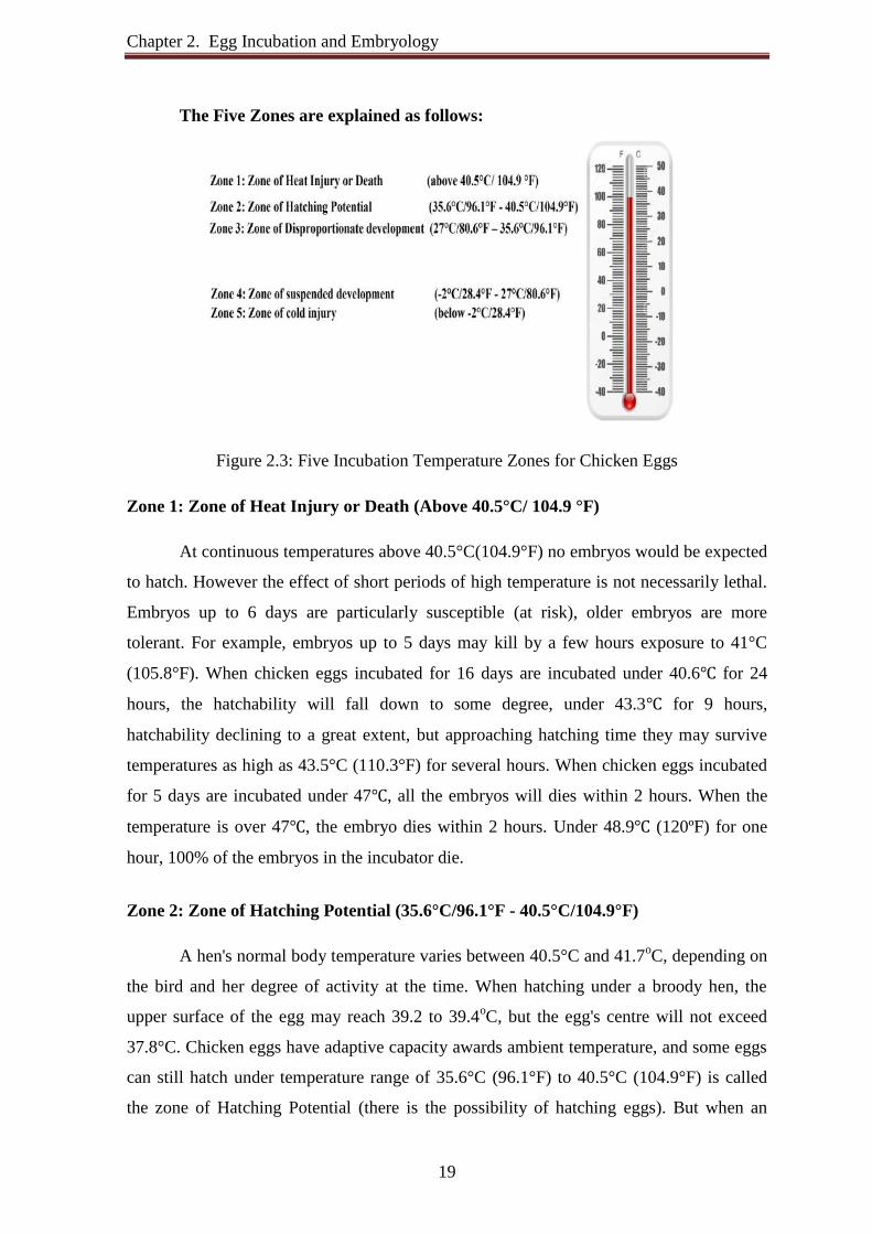
The Five Zones are explained as follows:
Figure 2.3: Five Incubation Temperature Zones for Chicken Eggs
Zone 1: Zone of Heat Injury or Death (Above 40.5°C/ 104.9 °F)
At continuous temperatures above 40.5°C(104.9°F) no embryos would be expected
to hatch. However the effect of short periods of high temperature is not necessarily lethal.
Embryos up to 6 days are particularly susceptible (at risk), older embryos are more
tolerant. For example, embryos up to 5 days may kill by a few hours exposure to 41°C
(105.8°F). When chicken eggs incubated for 16 days are incubated under 40.6℃ for 24
hours, the hatchability will fall down to some degree, under 43.3℃ for 9 hours,
hatchability declining to a great extent, but approaching hatching time they may survive
temperatures as high as 43.5°C (110.3°F) for several hours. When chicken eggs incubated
for 5 days are incubated under 47℃, all the embryos will dies within 2 hours. When the
temperature is over 47℃, the embryo dies within 2 hours. Under 48.9℃ (120ºF) for one
hour, 100% of the embryos in the incubator die.
Zone 2: Zone of Hatching Potential (35.6°C/96.1°F - 40.5°C/104.9°F)
A hen's normal body temperature varies between 40.5°C and 41.7oC, depending on
the bird and her degree of activity at the time. When hatching under a broody hen, the
upper surface of the egg may reach 39.2 to 39.4oC, but the egg's centre will not exceed
37.8°C. Chicken eggs have adaptive capacity awards ambient temperature, and some eggs
can still hatch under temperature range of 35.6°C (96.1°F) to 40.5°C (104.9°F) is called
the zone of Hatching Potential (there is the possibility of hatching eggs). But when an

Chapter 2. Egg Incubation and Embryology
20
incubation machine is use, the temperature mentioned above is not the most favorable
temperature because the developing embryo can only withstand small fluctuations during
the period. Therefore, it is essential to determine and use a temperature that promotes the
highest hatchability [30],[18] and the best hatchling quality [31], known as optimum
incubation temperature. Setting off optimum incubation temperature leads to the best
hatchability and chick quality [32],[18].
In order to hatch a good percentage of fertile eggs, an incubator must be able to
maintain a constant optimum incubation temperature. Several broad conclusions were
drawn in these reviews: optimum continuous incubation temperature for poultry is
between 37°C to 38°C. Optimum incubation temperature for avian embryos ranges from
37 to 37.5°C [32]. The optimum temperature for chicken egg in the setter (during the first
18 days) ranges from 37.5°C (99.50ºF) to 37.64°C (99.75ºF) and in the Hatcher (last 3
days) is 36.94°C (98.50º F). The best hatch obtained by keeping the temperature at 37.5°C
throughout the incubation period when using a forced-air incubator. Minor fluctuations
(less than 0.5°C) above or below were 37.5°C tolerated, but did not let the temperatures
vary more than a total of 1°C [33], which the implemented Microcontroller Based Forced
Air Egg Incubator (MBFAEI) can accurately provide.
In modern fan-forced incubators, the manufacturer's recommended temperature
setting is between 37.5ºC and 37.64ºC. The lethal temperature for eggs is 39.4ºC. The
constant and rapid air movement in this type of incubator keeps the eggs' temperature the
same as the incubators. Most of the large commercial type incubators and hatchers are run
at 37.22ºC (99ºF). On the other hand, most of the smaller incubators and hatchers, like
those commonly used by game bird producers, are run at 37.78oC (100ºF). Remote
monitoring of egg temperatures during natural incubation has found lower temperatures
than those commonly used for artificial incubation [32],[34].
An embryo's heat production increases as incubation progresses. The temperature
increase is greatest during the last two days due to embryo activity. Egg temperature rises
up to 2ºC above the incubator’s ambient air temperature, for this reason the temperature is
often lowered by up to 1oC during hatching. A decrease in incubation temperature by 2ºC
to 3ºC towards the end of incubation result in an improved embryo growth rate and
Chapter 2. Egg Incubation and Embryology
21
metabolism while decreasing embryonic mortality and improving chick quality at hatching
[35].
The effect of incubation temperature on egg hatchability and hatching quality may
be related to its influence on incubation length and water loss during incubation. However,
such effects depend on how long and how intense is the shift from optimum temperature.
Temperature fluctuations for short periods of time usually do not severely affect
hatchability or chick quality because the temperature inside the egg changes more slowly
than the air inside the incubator. Developing embryos are fairly tolerant of short-term
temperature drops and the user need not be concerned about cooling that occurs when
inspecting eggs. Therefore opening the incubator regularly to check fertility or for piped
eggs is probably not harmful and will also bring in fresh air. Some recommend that
artificially incubated eggs be cooled once a day to recreate the natural cooling which
occurs when the brooding parent leaves the nest to eat [36].
The embryo development is delayed in temperatures below optimum and
accelerated in temperatures above optimum [20],[29]. Embryo exposed to a lower than
optimal incubation temperature for more than 36 h also had improper positioning of the
embryo and reduced chick weight [37]. Incubation of eggs consistently at below optimal
temperatures resulted in a retard development, delayed hatching time, fewer pipped eggs,
and consequently a lower hatching rate [38]. The chicks may be large, soft bodied, and
weak. However it is again evident that early embryos are more susceptible to continuous
slightly low temperatures than older embryos. It is also reported that at low incubation
temperatures affect the timing of the onset of key physiological processes and their control
that specifically influence growth and maturation of the respiratory system [17].
The increase in temperature during incubation was very critical for embryos [39].
Overheating is much more critical than under heating, under high temperature, the chicken
embryo develops very fast, which may lead to a shortening of incubation period and hence
leads to increase of embryo death rate or decreases the quality of chicks.
The death rate may vary depending on the degree of the temperature overshooting
and the duration of this overheating. Embryos were very sensitive to acute high
temperature during early stages of incubation [40-41]. Moreover, it was reported that

Chapter 2. Egg Incubation and Embryology
22
growth was retarded or ceased and the incidence of poor second quality chicks increased
as the temperature was raised [29], and lower the percentage of hatchability [13].
Zone 3: Zone of Disproportionate Development (27°C/80.6°F – 35.6°C/96.1°F)
Eggs kept above 27°C (80.6°F) will start to develop, however the development will
be disproportionate in the sense that some parts of the embryo will develop faster than
others and some organs may not develop at all. Below 35°C (95°F) no embryo is likely to
survive to hatch. Typically the heart is much enlarged and the head development more
advanced than the trunk and limbs. Embryos in eggs that spend too much time in this zone
can develop unevenly, leading to crippling injuries or death. Successful hatching is greatly
reduced. When incubated under 35.6℃ (96.1ºF), most of the embryos die in the egg shells.
Little deviation from proper temperature will cause less influence to the embryonic
development, due to adjustment from embryo itself.
The temperature at the lower end of this range is sometimes referred to as
‘Physiological zero’- the threshold temperature for embryonic development. Unfortunately
different organs appear to have different thresholds resulting in an enviable entity.
Zone 4: Zone of Suspended Development (-2°C/28.4°F - 27°C/80.6°F):
Below about 27°C (80.6°F) no embryonic development takes place. Freshly laid
eggs can spend a lot of time at this temperature with no harm to the egg or embryo. Prior
to incubation, eggs must be stored in this temperature range (preferably around
15°C/59°F).
Zone 5: Zone of Cold Injury (Below -2°C/28.4°F):
Below this threshold ice crystals will start to form in the egg and permanent
damage may be done to internal structures. Eggs may lie for some considerable time in
temperatures close to freezing without suffering damage.
The analysis above gives us a fair idea of what may be happening to embryos kept
continuously or for long periods within these temperature bands. Further scientific data

Chapter 2. Egg Incubation and Embryology
23
has resulted from experiments concerned specifically with intermittent chilling of eggs.
There is evidence that, during the early phase of incubation, chilling of eggs to below
‘physiological zero’ does less harm than chilling to temperatures above that level.
Embryos up to 7 days old may well survive cooling to near freezing for 24 hours or more
without damage. The cooling delays hatching, but not by as much as the period of chilling,
so there appears to be some degree of compensation. The older the embryo, the more
likely it is to die as a result of chilling to below 27°C/80.6°F, but the effect on surviving
embryos is not detrimental.
A number of conclusions from this data which have practical implications that
cooling eggs for short periods, say 30 to 40 minutes, on a regular basis (say once every 24
hours) at any stage during incubation has no detrimental effect and is probably of benefit.
Certainly there is no evidence to suggest that short-term cooling is likely to be harmful. It
may also be best to treat eggs this way up to about the 14th day, although greater losses
must be expected if severe cooling occurs later in incubation. Incubator thermometer
readings will not be the same as embryonic temperatures when cooling or heating occurs.
The eggs will lag behind the air temperature. For example, cooling hens’ eggs by taking
them out of the incubator into a room at 20°C/68°F for 30-40 minutes is likely to cool the
internal egg temperature by only 3°C - 5°C (7°F - 10°F).
There is a very little data on the effects of cooling eggs of other species. Duck eggs
and to an even greater extent, goose eggs, are said to benefit from periodic cooling. The
eggs of both duck and domestic geese have been subjected to severe cooling for prolonged
periods without harm. There is an obvious analogy with the natural process in cooling
eggs periodically. Most species of bird leave the nest for short periods to feed. It is quite
possible that the resulting cooling and re-heating provides a stimulus to the embryo, which
actually encourages growth.
It needs to avoid subjecting the eggs to over-temperature at any time, but
particularly in the early days of incubation.

Chapter 2. Egg Incubation and Embryology
24
2.5.2 Eggs Position and Turning of Eggs
The eggs position and of turning of eggs are very important during egg incubation.
The proper egg position and turning of the eggs facilitate position of developing embryos
and ensure that nutrients are evenly distributed for embryonic development. Egg Position:
It is natural that the head of the embryo develops toward the large end of the egg
where the air cell is located. In this region each hatching egg should be positioned with the
large end up or horizontally with the large end slightly elevated during incubation. The
proper orientation of the incubating eggs shown in Figure 2.4. This enables the embryo to
remain oriented in a proper position for hatching. When the eggs are incubated with the
small end up, about 60% of the embryos will disorient and develop with the head near the
small end. Thus, when the chick is ready to hatch, its beak cannot break into the air cell to
initiate pulmonary respiration, the chick is likely to drown on pipping and will not hatch.
Figure 2.4: The Proper Orientation of the Egg During Incubation
Eggs positioned horizontally will incubate and hatch normally as long as they are
turned frequently. Under normal circumstances, the eggs are set with large end up for the
first 18 days (in setter) and in horizontal position for the last 3 days (in hatcher). Never set
eggs with the small end upward. When setting in trays, the proper orientation of the egg
during incubation is with the small end pointed down. The air cell should grow at the blunt
end.
Turning of Eggs:
Turning of eggs is very important to fulfill necessary condition for the successful
development of the embryo. The albumen (white) of an egg contains virtually no fat
particles and has a specific gravity near that of water. The yolk has a relatively high fat

Chapter 2. Egg Incubation and Embryology
25
content. Fats and oils have specific gravities lower than water and float on water. The egg
yolk tries to do the same thing float on the albumen. If an egg is left in one position and
not turned, the yolk tends to float upward through the albumen toward the shell and pushes
the embryo nearer the shell. If the yolk travels rise enough, the developing embryo is
squeezed between the yolk and shell and the embryo will stick to the shell and
development can be fatally distorted or the chick may be malpositioned for proper
hatching or the embryo can be damaged or killed. Turning the egg causes the yolk to be
repositioned away from the shell, making it safe for the developing embryo until time to
turn the egg again and prevents the embryo from sticking to the shell membranes. Turning
of eggs during incubation prevents the developing embryo adhering to the extra-
embryonic membranes and reduces the possibility of embryo mortality and unhealthy
hatches. By this way turning regulates accumulation of protein in amniotic fluid, affecting
embryo growth, hatchability and consequently chick quality. Turning also influences
thyroid hormone levels and corticosteroid production, affecting embryonic response to
stress. It prevents the germ from migrating through the albumen and adhering to the shell.
Moreover, as the embryo develops on the yolk, it causes that part of the yolk to become
lighter and float upwards. The importance of egg turning has been documented in several
studies.
The egg turning is critical for the first week when the embryo has no circulation
system. The turning in the first week of incubation enables proper formation of extra-
embryonic membrane [42]. Egg turning facilitated the transfer of yolk nutrients to the
embryo via the sub-embryonic fluid [43]. Eggs must be turned at least five times within a
24-hour period or better still once every two hours for the first 75% of the incubation
period.
Turning more frequently is better; an automatic turner is recommended. If the
incubator is equipped with an automatic turner, eggs will be turned at least every few
hours. In large commercial incubators the eggs are turned automatically each hour i.e., 24
times a day. Egg turning is particularly crucial during the first 8 days, after the first week,
eggs still need to be turned, but not as often. Take extra precautions when turning eggs
during the first week of incubation. An error in machine programming can lead to 70%
death among embryos. The developing embryos have delicate blood vessels that rupture
easily when severely jarred or shaken, thus killing the embryo. Turning is essential during

Chapter 2. Egg Incubation and Embryology
26
the first 14 days of incubation and after the first 15 days, egg turning becomes somewhat
more optional. The turning of chicken eggs can be stopped at 16 days (normal incubation
period 21 days) without adversely affecting hatchability [44]. After 18 days, the embryos
are moving into hatching position and turning is not required in hatcher. The incubator
needs to close during hatching to maintain proper temperature and humidity. The air vents
should be almost fully open during the latter stages of hatching.
For small incubators good results can be obtained by turning the eggs the first
thing in the morning, again at noon, and the last thing at night. It is best to turn the eggs
more than three times a day, they should be turned an odd number of times so that the egg
will not be in the same position every night because that is the longest stretch of time
between turns. Eggs in small incubators in the home sometimes get turned only twice a
day, once in the morning and again in the evening. It may be helpful to place an “X” on
one side of each egg and an “O” on the other side, using a pencil. This serves as an aide to
determine whether all eggs are turned. During egg turning, be sure hands are free of all
greasy or dusty substances. Eggs soiled with oils suffer from reduced hatchability.
There is some controversy over the positioning of the egg, on rollers or in a tray.
Rollers are able to turn the eggs completely and the eggs can be set in a more natural
horizontal position. No scientific studies have compared rollers versus trays although
some breeders report better success with rollers.
Figure 2.5: Egg Tray Turning Method
Most commercial incubators are provided with plastic egg trays that hold the egg
vertically, with the small end down. The tray is then tilted through an angle of about 40º
either side of horizontal (an overall angle of 80º). The egg tray turning method is shown in
Figure 2.5. This method works well with poultry for which it was developed, and is very
efficient to operate on a commercial scale. However this is very different from the natural
process adopted by birds.

Chapter 2. Egg Incubation and Embryology
27
In this project tilting trays turning method with an angle of about 40º either side of
horizontal used.
2.5.3 Humidity
Humidity is one of most critical incubation factors which must be controlled
during egg incubation also it is difficult to measure and control accurately. Incubation
humidity determines the rate of moisture loss from the eggs during incubation. In general,
the humidity is recorded as relative humidity. Relative humidity (RH) is a measure of the
amount of moisture (water vapor) in the air relative to the total amount of moisture the air
can hold. Warmer air can hold more moisture than colder air. Because maximum possible
water content increases at higher temperature, if the temperature was increased, but no
additional water added then, the % RH level would drop.
The relative humidity is expressed as a percentage, so the maximum is 100 %. The
formula for relative humidity is:
One of the most reliable, cheap methods of measuring relative humidity is to
measure wet and dry bulb temperatures and convert the information to %RH by using a
simple chart. Some incubator industry refers to the level of humidity in terms of degrees
F., (wet-bulb) rather than percent relative humidity. The two terms are inter-convertible
and actual humidity depends upon the temperature (F) as measured with a dry-bulb
thermometer. Conversion between the two humidity measurements can be made using a
psychometric table.
Egg shells are porous-the average chicken egg has thousands of pores running
through the shell allowing the embryo to exchange oxygen, carbon dioxide and water.
Soon after an egg is laid, a small air bubble or “air cell” forms in the large end of the egg
of this water loss. During incubation moisture is lost from the egg through the tiny holes in
the shell; this increases the size of the air cell, which after 19 days of incubation occupies
about one-third of the egg [45]. The air cell is crucial for the chick to break out of the egg

Chapter 2. Egg Incubation and Embryology
28
shell at the end of the incubation period. The chick can drown if the air cell is too small or
the chick may be retarded in growth if the air cell is too large.
The amount of water that an egg loses during incubation is important and this is
determined by the humidity levels within an incubator; if the air is too dry the humidity
level is too low it causes excess evaporation of water, while humidity is too high prevents
the evaporation of sufficient amount of water from the egg. This hatching problem called
red hocks. These chicks could possibly suffer from weak legs [33]. In both cases,
hatchability is reduced [45]. This is why maintaining the proper humidity is crucial. Too
low or too high water loss influences embryo development, and consequently, egg
hatchability [46]. The amount of moisture lost from the eggs during incubation can affect
hatchability [22] and chick weight [47]. Slightly lower humidity levels are more likely to
be less disastrous than slightly higher humidity levels.
Recommended incubation relative humidity for the first 18 days ranging between
55% and 60% (in Setter) and for the last 3 days ranging between 65% and 75% (in
Hatcher). Higher humidity during hatching period is given to avoid dehydration of chicks.
Although a variation of 5 to 10% is acceptable. For higher hatchability the relative
humidity of air within an incubator for the first 18 days should be about 60% during the
last 3days (matching period) should be nearer 70%.
An egg must lose approximately 13-14% of its weight during the incubation
process. For best hatchability, an egg must lose 12% of its weight by 18 days of
incubation. The air cell of the egg should become larger as incubation progresses. Chicken
eggs will lose 12 percent to 14 percent of their total weight by evaporation during
incubation. The mean total weight loss of piped eggs was 12.1% for artificial and 16.0%
for natural incubation [48].
The weight loss rate from lay to pip is linear if the eggs are exposed to the same
temperature and humidity during this period [49] and can be controlled by differing the
level of humidity in the incubator. If the egg is losing weight too quickly, raising the
humidity will slow the rate of evaporation through the egg's pores and conversely
lowering the humidity will increase the rate of weight loss. Convection or a draft created
by the incubator fan has a minimal effect on egg water loss [50].

Chapter 2. Egg Incubation and Embryology
29
The weight loss rate after piping and up to hatching may be greater than that during
the “setting” period of incubation. The optimum weight loss of eggs during incubation is
shown in Figure 2.6. To determine the entire incubation weight loss the egg should be
weighed moments before hatching which is difficult to time correctly. As the embryo was
turning in the egg and determined that peregrine eggs lost 2.2% of the fresh egg weight
between piping and hatching in a forced air hatcher set at 37.0°C and 60% humidity. This
weight loss could be used as an approximate estimate for other altricial (pattern of growth
and development in organisms which are incapable of moving around on their own soon
after hatching or being born) species to add to lay to pipe data to determine the total
fractional weight loss over the entire incubation period.
Figure 2.6: Optimum Weight Loss of Eggs during Incubation
Incubator humidity has correlation with incubator temperature, ventilation forced
air fan speed and also with incubator room humidity. The temperature can highly
influence the relative humidity, and both contribute to water loss during incubation, this
way temperature and humidity must be carefully monitored during incubation, because the
embryo is not able to control the water loss of egg. For optimum hatchability during
incubation, eggs need to lose 11-14% of their weight in the form of water vapors.
Incubation temperatures above the optimum cause excessive egg water loss (higher than
14%), leading to embryo mortality by dehydration. On the other hand, temperatures below
the optimum decrease hatchability due to reduced water loss (< 12%), which causes an
over-hydration of the embryo and an impairment of gas exchange [31].
If by restricting ventilation the humidity is made too high (92 ºF to 94ºF) during
the final stages of incubation, the embryos are moist and develop to the 19th, 20th, or 21st

Chapter 2. Egg Incubation and Embryology
30
day of incubation, but die in the shell from suffocation. This suffocation results from
improper ventilation rather than high humidity.
Effect of Higher Humidity:
In natural incubation the membranes cannot dry quickly because the parent bird is
sitting on the egg but in an incubator drying membranes can be a problem, but for artificial
incubation higher humidity levels are required to prevent the membranes of egg drying too
fast as the chick hatches and becoming tough and difficult to tear. The actual level of
humidity is not too critical for hatching but needs to be at least 60% RH.
If the humidity in the incubator is too high during incubation, too little water will
evaporate from the egg, in that case the air space will be too small, the chick’s respiration
will be affected and the young bird will have difficulty breaking out of the shell because of
the lack of space. The chick will either drown or the chick will be too swollen with water
to turn itself within the egg. The yolk sac will also be too large for the navel to completely
close. These problems will cause the hatch to fail.
If several large, soft bodied, mushy chicks are observed that make it through
pipping and hatching but are dead in the tray, it is a sign of high humidity. A bad odor
usually accompanies this condition. The condition normally occurs only in incubators and
hatchers that have forced spray humidity systems that force too much moisture into the
machines. Rarely does humidity run too high on a machine that relies on evaporation from
pans if you are using the recommended evaporative pans, if the temperature is correct, and
if the machines are properly and amply ventilated with fresh air.
Effect of Lower Humidity:
Low incubation humidity levels lead to small chicks with large air spaces by the
time the hatch is due. These chicks will tend to be weak and may also die just before,
during or just after hatching. It should be noted that in general that a slightly lower
humidity level than optimum is likely to be less disastrous than a slightly higher than ideal
level.

Chapter 2. Egg Incubation and Embryology
31
Excessive moisture loss from the eggs during storage before setting can produce
the same symptoms that low humidity in the machines produces. A sign of low humidity is
sticky embryos during piping and hatching that results in embryos not being able to turn
themselves in the shell and complete the act of piping and detaching themselves from the
shell. Low humidity also results in short down on the chicks, malformed, malpositioned,
weak, and small chicks. Low humidity contributes to (but is not wholly responsible for)
spraddlers, star gazers, and those that cannot stand, walk, or orient themselves well enough
to reach food and water.
When humidity is too low during incubation, too little moisture results in excessive
evaporation, the air cell did too large at the time of hatch causing chicks to stick to the
shell sometimes and hatch crippled at hatching time. The contents of the egg will be too
thick and sticky for the chick to turn. The membranes will be too tough to break. The
navel will not close properly.
An egg loses 11-13 per cent of its inherent moisture during incubation. If humidity
is too low, the moisture loss is excessive, hatching is delayed and many embryos fail to
hatch even if they go to full term. If humidity is too high, the chicks tend to be forced out
early and are wet.
The relative humidity of the air within an incubator for the first 18 days should be
able 60 percent. During the last 3 days (the hatching period) the relative humidity should
be nearer 65-70 percent.
Controlling Humidity:
Humidity needs to carefully control to prevent unnecessary loss of egg moisture.
Setters will need to be adjusted to ensure that the weight loss of the egg is 12% by 18 days
of incubation. The relative humidity in the incubator between setting and 3 days prior to
hatching should remain at 58%-60% or 84-86º F wet-bulb during incubation is
satisfactory. On day 19, the humidity needs to raise about 65% -70% for hatching. By this
stage the weight loss of the egg should be 13-15% and water loss for the last 24-48 hours
will not significantly affect this. Then, towards the end of the day 21 when all chicks that
are likely to hatch have hatched, reduce humidity to 60 per cent. This enables chicks to dry
off before being taken out.

Chapter 2. Egg Incubation and Embryology
Achieving Correct Humidity Levels Humidity can control by the size of the intake
shutting ventilation holes, However proper ventilation is needed to provide O2 and remove
CO2 from the incubator and restriction of this flo
recommended.
Incubators and hatchers have pans filled with water to create humid conditions and
to provide humidity inside the incubator. The water's surface area rather than depth
influence humidity. The total sur
adjusted until the correct humidity is achieved.
Humidity can be control
over the water tray. During the hatching period, using an atomizer to
of water into the ventilating holes may increase the humidity in the incubator. This is
especially helpful when duck o
Achieving Correct Humidity Levels by
Figure 2.7
It is also possible to determine whether there is too much or too little humidity in
the incubator by candling the eggs and observing the size of the air cells and marking air
cells and also by weighing. The growth of this air cell is a balance between tem
and humidity during the incubation.
shown in Figure 2.7. Racks of eggs can be weighed during incubation to detect problems
with humidity and evapora
Egg Incubation and Embryology
32
Correct Humidity Levels by Changing Water's Surface:
Humidity can control by the size of the intake-exhaust air vents and by opening or
shutting ventilation holes, However proper ventilation is needed to provide O2 and remove
CO2 from the incubator and restriction of this flow to increase incubator humidity is not
Incubators and hatchers have pans filled with water to create humid conditions and
to provide humidity inside the incubator. The water's surface area rather than depth
influence humidity. The total surface area of water determines the humidity and should be
adjusted until the correct humidity is achieved.
controlled by using the water tray’s position or moving slides
over the water tray. During the hatching period, using an atomizer to spray a small amount
of water into the ventilating holes may increase the humidity in the incubator. This is
especially helpful when duck or goose eggs are being hatched.
Correct Humidity Levels by the Size of the Air Cells:
7: The Growth of Air Cell during the Incubation
It is also possible to determine whether there is too much or too little humidity in
the incubator by candling the eggs and observing the size of the air cells and marking air
cells and also by weighing. The growth of this air cell is a balance between tem
and humidity during the incubation. The proper growth of air cell during the incubation
Racks of eggs can be weighed during incubation to detect problems
with humidity and evaporate loss before a hatch is destroyed.
exhaust air vents and by opening or
shutting ventilation holes, However proper ventilation is needed to provide O2 and remove
w to increase incubator humidity is not
Incubators and hatchers have pans filled with water to create humid conditions and
to provide humidity inside the incubator. The water's surface area rather than depth
face area of water determines the humidity and should be
s position or moving slides
spray a small amount
of water into the ventilating holes may increase the humidity in the incubator. This is
the Incubation
It is also possible to determine whether there is too much or too little humidity in
the incubator by candling the eggs and observing the size of the air cells and marking air
cells and also by weighing. The growth of this air cell is a balance between temperature
growth of air cell during the incubation is
Racks of eggs can be weighed during incubation to detect problems
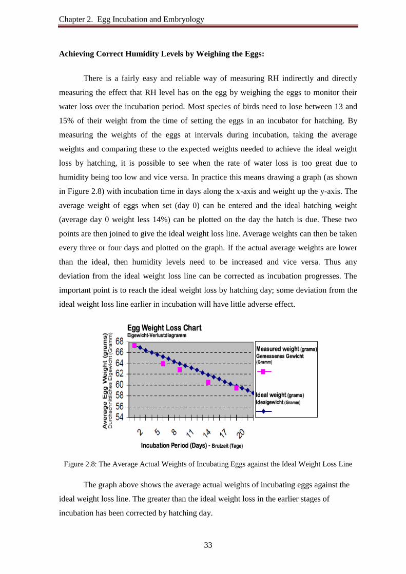
Chapter 2. Egg Incubation and Embryology
33
Achieving Correct Humidity Levels by Weighing the Eggs:
There is a fairly easy and reliable way of measuring RH indirectly and directly
measuring the effect that RH level has on the egg by weighing the eggs to monitor their
water loss over the incubation period. Most species of birds need to lose between 13 and
15% of their weight from the time of setting the eggs in an incubator for hatching. By
measuring the weights of the eggs at intervals during incubation, taking the average
weights and comparing these to the expected weights needed to achieve the ideal weight
loss by hatching, it is possible to see when the rate of water loss is too great due to
humidity being too low and vice versa. In practice this means drawing a graph (as shown
in Figure 2.8) with incubation time in days along the x-axis and weight up the y-axis. The
average weight of eggs when set (day 0) can be entered and the ideal hatching weight
(average day 0 weight less 14%) can be plotted on the day the hatch is due. These two
points are then joined to give the ideal weight loss line. Average weights can then be taken
every three or four days and plotted on the graph. If the actual average weights are lower
than the ideal, then humidity levels need to be increased and vice versa. Thus any
deviation from the ideal weight loss line can be corrected as incubation progresses. The
important point is to reach the ideal weight loss by hatching day; some deviation from the
ideal weight loss line earlier in incubation will have little adverse effect.
Figure 2.8: The Average Actual Weights of Incubating Eggs against the Ideal Weight Loss Line
The graph above shows the average actual weights of incubating eggs against the
ideal weight loss line. The greater than the ideal weight loss in the earlier stages of
incubation has been corrected by hatching day.

Chapter 2. Egg Incubation and Embryology
34
The Importance of Keeping the Incubator Closed During the Hatching Period:
To increase humidity within an incubator it is very important to keep the incubator
closed for in the last 3 days of incubation. Humidity levels drop rapidly when the
incubator is opened and took much longer than temperature levels to re-establish. It is very
tempting to keep opening and checking or wanting to help a baby chick out of the shell.
Normally the chick does just fine on its own. The hatching may take several hours. Do not
rush the chick. Many chicks have died in the shell without having the opportunity to hatch
because someone just could not leave the incubator closed during this critical time.
2.5.4 Ventilation and Oxygen Availability
Ventilation is very important during the incubation process. Egg shells contain
three to six thousand small holes, called “pores”, oxygen enters the egg through the shell
and carbon dioxide escapes in the same manner. The embryo's lungs are not developed
during early embryonic development to the point that they can accommodate respiration
by breathing. Respiration, therefore, is provided during the first three to five days by the
vitelline blood circulation plexus growing from the embryo. To reach this plexus the
gaseous exchange must travel through the egg pores and the albumen (egg white) to reach
the vitelline circulation, which lies on the surface of the egg yolk. After the 4th or 5th day
of development another structure, called the “allantois” grows from the embryo, extends
through the albumen, and positions itself just underneath the egg shell. The allantois
becomes the primary respiratory organ of the developing embryo and remains such until
just before piping begins. The transfer of respiratory function from the allantois to the
lungs begins three or four days before pipping. The transfer is gradual and is completed by
the time the chick finishes pipping the egg shell. The important thing to remember about
embryonic respiration is that ventilation is important throughout the incubation process,
especially toward the end, because the embryos are larger and respiring at a much higher
rate than in the beginning. The egg breathes, taking in oxygen (7 grams in 21 days) and
giving off carbon dioxide (9 grams).
Ventilation must be minimal at the beginning of hatching in order to help initiate
pulmonary respiration (which is prompted by a high-level of carbon dioxide), and later
must be increased until becoming maximal at the end of hatching. If ventilation is poor the

Chapter 2. Egg Incubation and Embryology
35
first thing noticed may be a poor hatch. Lack of proper ventilation can contribute to low
hatchability if, after examining numerous dead embryos in the shell, the majority of
embryos reaches the 19th or 20th day of incubation. Ventilation is a major factor at the end
of the cycle.
The fresh air drawn from the incubation room therefore provides the eggs with the
oxygen and humidity that they need, and takes away the carbon dioxide and excessive heat
that they produce. As embryos grow, the air vent openings are gradually opened to satisfy
increased embryonic oxygen demand. The supply of fresh air must be sufficient to prevent
a lack of oxygen and choking. Care must be taken to maintain humidity during the
hatching period. Unobstructed ventilation holes, both above and below the eggs, are
essential for proper air exchange.
The best hatching results are obtained with normal atmospheric air, which usually
contains 21 percent oxygen and approximately 0.4% for carbon dioxide (0.2% during the
first phase and 0.5% at the time of transfer). For every 1% drop in oxygen there is 5%
reduction in hatchability. The tolerance level of CO2 for the first 4 days in the setter is
0.3%. CO2 levels above 0.5% in the setter reduce hatchability and completely lethal at
5.0%. Since the normal oxygen and carbon dioxide concentration presents in the air seem
to represent an optimum gaseous environment for incubating egg, no special provision to
control these gases is necessary other than to maintain adequate circulation of fresh-air at
the proper temperature and humidity. It is difficult to provide too much oxygen, but a
deficiency is possible. Make sure that the ventilation holes are open to allow a normal
exchange of air. The air supply to the setter room should be 8cfm (13.52 cubic meters hr)
per 1000 eggs.
2.5.5 Sanitation
Good sanitation must be maintained to prevent disease in the hatchery. The
conditions provided to maintain embryonic growth in the incubators are also ideal for the
growth of bacteria and molds. Good design is essential for cost-effective incubator
operation. Incubators should have the durable wall; wall surfaces should have a minimum
of joints and fastenings that impede effective cleaning.
Chapter 2. Egg Incubation and Embryology
36
It is imperative that people wash and sanitize their hands before collecting eggs
from the nests or egg belts. The flats that eggs are placed on must also be sanitized and
free of organic material. Birds need to provide clean and nest place for egg laying and
collect hatching eggs three times a day. Eggs laid in dirty place can be covered by
contaminating microorganisms from the feces or feather material of the parents or
previous nestlings. Dirty, cracked, or porous eggs will not set for incubation. The washing
and rubbing action also serves to force disease organisms through the pores of the
shell. Omphalitis, yolk sack infection is caused by a bacterium that enters through the
porous egg shell and easily kills embryo's and newly hatched chicks. Unfortunately,
incubation conditions are ideal for breeding bacteria as well as incubating eggs. Eggs that
are of good size, not abnormally big or small, clean should be select for hatching. Soiled
eggs should be carefully dry cleaned by gently buffing the soiled area with fine sandpaper
or steel wool.
Eggs should not be washed. Washing or wiping with a damp cloth removes a
protective layer that coats the egg. Washing eggs transfers disease infection agents from
the surface to the inside of the eggs. Contraction of egg contents draws water into the egg
through pores in the shell. This water carries infecting microorganisms into the egg. If an
egg is washed, it should be washed briefly in 110-degree F water that contains a
commercial egg sanitizer. Washing an egg in water that is cooler than the egg itself causes
egg contents to contract.
It is essential to use a disinfectant, which is formulated to be used for cleaning
eggs, incubators, safe and effective against yeasts, fungi, viruses and bacteria which can
cause fatal damage to the growing embryo. Fumigation of eggs has been a common
method to kill shell surface micro-organisms. Fumigation should only be done with fresh
eggs, older eggs can be killed. Incubators made out of porous wood or polystyrene and
others with hard to reach areas can only be effectively disinfected by fumigation. Eggs to
be hatched should always be put into a place with proper sanitation.
The pans of water used in incubators for humidity control, provide growing media
for pathogenic bacteria, especially in the warm environment of an incubator, and should be
disinfected periodically. Use distilled water or the use of boiled water that has been
Chapter 2. Egg Incubation and Embryology
37
cooled, in incubator trays will reduce the chance of unwanted organisms being introduced
from the tap water. Whenever adding water to an incubator, it should be about the same
temperature as the incubator, a good test is to add water just warm to the touch.
Omphalitis, Mushy Chick Disease and Yolk Sack Infection may be caused by a bacterium
that enters through the porous egg shell.
Broken, infertile and spoiled eggs need to remove as soon as possible. When
chicks and ducklings start to hatch, egg shells and weak or dead chicks remove
immediately. After all the eggs have hatched, remove the trays and cloth liners and wash
and disinfect them thoroughly.
Sources of contamination other than infected eggs and chick fluff are airs, people
(both workers and visitors), animals such as rats and mice, wild birds and insects, and
equipment such as boxes, trays and buggies.
It needs to ensure that all workers and visitors wear suitable protective clothing. It
is good practice to use different colored uniforms according to location (clean or dirty part
of the hatchery) or task. This helps to identify incorrect movement of workers and hence
possible cross contamination.
2.6 Length of Incubation
Chicken eggs require 21 days to hatch, but the incubation period for the eggs of
other species of poultry varies. The incubator period and incubator operation for eggs of
domestic birds are shown in Table 2.1:

Chapter 2. Egg Incubation and Embryology
38
Table 2.1: The Incubation Period and Incubator Operation for Common Domestic Birds (Part-1)
Chicken Duck Coturnix Quail Pigeon
Egg Storage before Incubation
Egg Storage before Incubation <8 days <7 days <7 days <7 days Temperature 13ºC -18ºC 13ºC -18ºC 13ºC -18ºC 13ºC -18ºC Best Temperature 55ºF(13ºC) 55ºF(13ºC) 55ºF(13ºC) 55ºF(13ºC) Humidity 70‐85% RH 70‐85% RH 70‐85% RH 70‐85% RH Best Humidity 75% RH 75% RH 75% RH 75% RH
Incubation Period (Days)
Incubation Period (days) 21 28 17 17 Successful Incubation (days) 20-22 27-29 17-18 17-18
Setter Operation
Temperature 37.5ºC-37.64ºC 37.5ºC-37.64ºC 37.5ºC-37.64ºC 37.2ºC-37.5ºC Best Temperature 37.5ºC
(99.5ºF) 37.28ºC (99.1ºF)
37.64ºC (99.75ºF)
37.64ºC (99.75ºF)
Humidity (% rH) 55%-60% 55%-60% 45%-55% 45%-55% Best Humidity (% rH) 55% 55% 55% 55% Egg turning per day (Manual) 8 times 8 times 8 times Egg turning per day (Automatic) 24 times 24 times 24 times
Hatcher Operation
Do Not Turn Eggs After 19 th day 25th day 15th day 15th day Temperature 36.94ºC-37.22ºC 36.89ºC-37.01ºC 37.22ºC 37.22ºC Best Temperature 36.94ºC
(98.5ºF) 36.89ºC (98.4ºF)
37.22ºC (99ºF)
37.22ºC (99ºF)
Humidity (% rH) 65%-70% 65%-70% 55%-65% 55%-65% Best Humidity (% rH) 65% 65% 60% 60% Increase Ventilation 10 th and
18 th day 12th day and
25th day
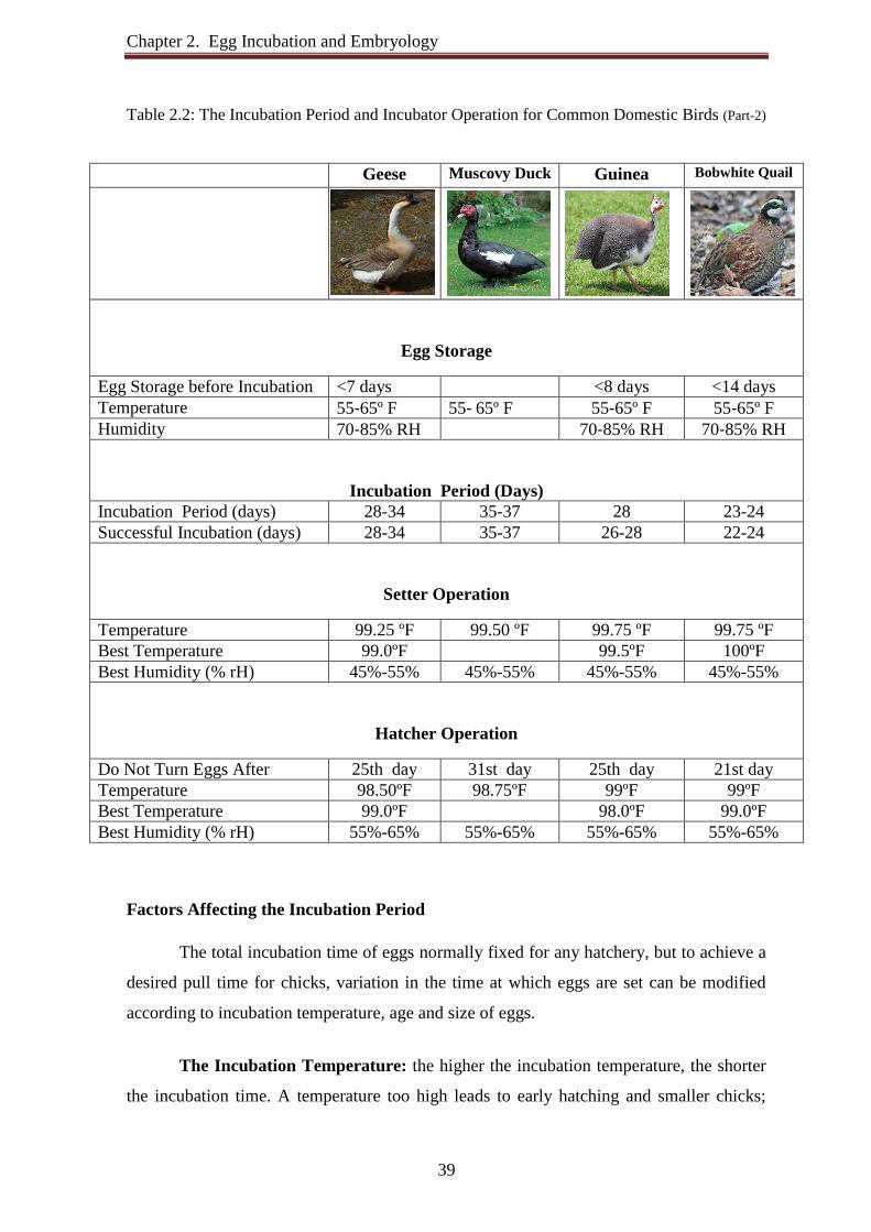
Chapter 2. Egg Incubation and Embryology
39
Table 2.2: The Incubation Period and Incubator Operation for Common Domestic Birds (Part-2)
Geese Muscovy Duck
Guinea Bobwhite Quail
Egg Storage
Egg Storage before Incubation <7 days <8 days <14 days Temperature 55‐65º F 55‐ 65º F 55‐65º F 55‐65º F Humidity 70‐85% RH 70‐85% RH 70‐85% RH
Incubation Period (Days) Incubation Period (days) 28-34 35-37 28 23-24 Successful Incubation (days) 28-34 35-37 26-28 22-24
Setter Operation
Temperature 99.25 ºF 99.50 ºF 99.75 ºF 99.75 ºF Best Temperature 99.0ºF 99.5ºF 100ºF Best Humidity (% rH) 45%-55% 45%-55% 45%-55% 45%-55%
Hatcher Operation
Do Not Turn Eggs After 25th day 31st day 25th day 21st day Temperature 98.50ºF 98.75ºF 99ºF 99ºF Best Temperature 99.0ºF 98.0ºF 99.0ºF Best Humidity (% rH) 55%-65% 55%-65% 55%-65% 55%-65%
Factors Affecting the Incubation Period
The total incubation time of eggs normally fixed for any hatchery, but to achieve a
desired pull time for chicks, variation in the time at which eggs are set can be modified
according to incubation temperature, age and size of eggs.
The Incubation Temperature: the higher the incubation temperature, the shorter
the incubation time. A temperature too high leads to early hatching and smaller chicks;

Chapter 2. Egg Incubation and Embryology
40
whereas a temperature too low results in hatching delay from 2 to 12 hours depending on
temperature, and larger chicks. In both cases, extremes also lead to an increase in
embryonic mortality.
The Age of the Eggs: stored eggs take longer to incubate, beyond 5/6 days of
storage, each additional day prolongs the incubation time by one hour.
The Size of the Eggs: larger eggs take longer to incubate, beyond 50 grams, each
2.5gram range prolongs the incubation time by half an hour.
Numerous secondary factors also influence incubation time: breed (layer type or
meat type chickens), period of the year, the number and type of eggs in the incubator, type
of incubator used.
2.7 Monitoring of Eggs and the Incubator
Eggs need to be monitored during incubation to determine embryo progress and
where incubation adjustment may be necessary.
Candling is the process of shining light with a concentrated beam that may be
shone through the shell of the egg to illuminate the egg contents to determine whether the
egg is fertile, infertile or spoiled. It allows the size of the airspace to be determined which
offers a guide to the weight loss rate.
If the air space is larger than expected too much water is being lost and the
humidity in the incubator should be increased to reduce the rate of water loss. If the air
space is smaller than expected, then the opposite applies.
The candling recommends on Day 7 and Day 14 for chicken eggs, and Day 7 and
21 for duck eggs. The principle is simple: In a dark room a source of light is placed against
the eggshell, and the light passes through illuminating its contents. If the egg is fertile a
tiny network of blood vessels emerging from a dark red spot (similar to a spider) will be
seen (see photo below). If the egg is infertile the yolk will appear as a floating shadow
with no sign of blood vessels and if the egg is spoiled it will appear opaque.
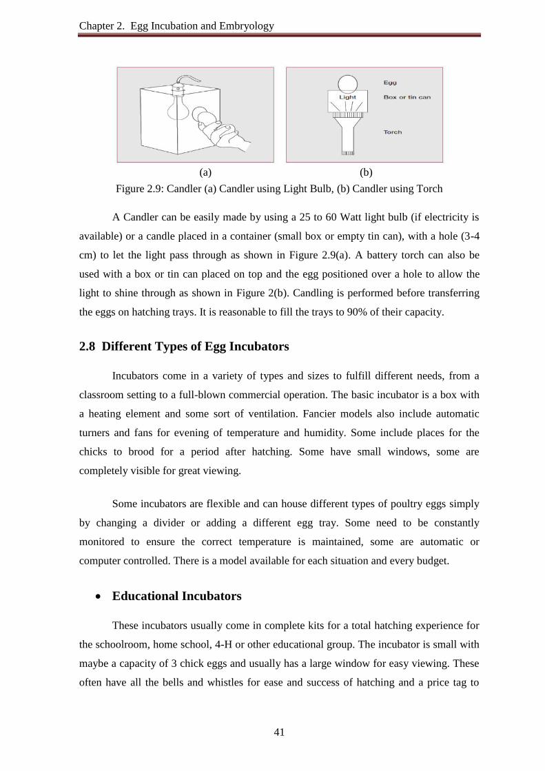
Chapter 2. Egg Incubation and Embryology
41
Figure 2.9: Candler (a) Candler using Light Bulb, (b) Candler using Torch
A Candler can be easily made by using a 25 to 60 Watt light bulb (if electricity is
available) or a candle placed in a container (small box or empty tin can), with a hole (3-4
cm) to let the light pass through as shown in Figure 2.9(a). A battery torch can also be
used with a box or tin can placed on top and the egg positioned over a hole to allow the
light to shine through as shown in Figure 2(b). Candling is performed before transferring
the eggs on hatching trays. It is reasonable to fill the trays to 90% of their capacity.
2.8 Different Types of Egg Incubators
Incubators come in a variety of types and sizes to fulfill different needs, from a
classroom setting to a full-blown commercial operation. The basic incubator is a box with
a heating element and some sort of ventilation. Fancier models also include automatic
turners and fans for evening of temperature and humidity. Some include places for the
chicks to brood for a period after hatching. Some have small windows, some are
completely visible for great viewing.
Some incubators are flexible and can house different types of poultry eggs simply
by changing a divider or adding a different egg tray. Some need to be constantly
monitored to ensure the correct temperature is maintained, some are automatic or
computer controlled. There is a model available for each situation and every budget.
Educational Incubators
These incubators usually come in complete kits for a total hatching experience for
the schoolroom, home school, 4-H or other educational group. The incubator is small with
maybe a capacity of 3 chick eggs and usually has a large window for easy viewing. These
often have all the bells and whistles for ease and success of hatching and a price tag to
(a) (b)

Chapter 2. Egg Incubation and Embryology
42
match. It is possible to purchase just the small incubator for about $20 or the whole kit and
caboodle, including small brooder for $300-$400.
Small Hobby Farm Incubators
There are a variety of incubators available for the hobby farmer with a backyard
flock. A basic Styrofoam model can hold 30-40 chicken eggs, with no fan or automatic
turner for the cheapest alternative. Add the fan and turner for a more consistent
temperature and increased hatchability. There are also fancier models with more reliable
controls and long-term reliability. Extra attachments are available for some models that
allow a variety of eggs to be used (chicken or quail or duck etc.) The prices in this
category range from $50 to over $600.
Large Capacity Incubators
For the more serious enthusiast or commercial enterprise there are large capacity
incubators. Hundreds of eggs can be hatched at once, some with staggered hatching dates
so that a new batch is ready every week. These units are computer run for precise
management of all the parameters and fantastic hatch rate. These incubators start at $750
and go up from there, depending on size and features.
2.9 Size of Incubator
The size and type of incubator selected depends on the needs and future plans of
each producer. Many different models are available. For continuous settings, separate
incubator and hatcher units are recommended. If all eggs in the unit are at the same stage
of incubation, a single unit can be used.
Locate the incubator and Hatcher units indoors to protect them from major weather
changes. It is essential that the room has a good ventilation system to supply plenty of
fresh air. Keeping the units indoors makes it easier to maintain uniform temperature and
humidity. The size and type of incubator selected depends on the needs and future plans of
each producer. Many different models are available. For continuous settings, separate
incubator and hatcher units are recommended. If all eggs in the unit are at the same stage
of incubation, a single unit can be used.

Chapter 2. Egg Incubation and Embryology
43
Locate the incubator and hatcher units indoors to protect them from major weather
changes. It is essential that the room has a good ventilation system to supply plenty of
fresh air. Keeping the units indoors makes it easier to maintain uniform temperature and
humidity.
2.10 Incubator Construction and Function
Incubators are machines, which artificially provide the egg with the correct,
controlled environment for the developing chick. Depending on complexity, an incubator
will give varying degrees of control over temperature, humidity, egg turning, fresh air
flow and hygiene, while providing a secure place for the eggs.
There are two types of incubators depending on construction, function and the
process of surrounding the egg with warm air. These are the much smaller still-air type
used for incubating small numbers of eggs and the larger forced-air type found in
commercial hatcheries.
2.10.1 Still Air Incubators
Still air incubators are the most basic form of incubator. The typical still-air egg
incubator shown in Figure 2.10. The air inside a still air incubator circulates by
convection. As the air is heated it expands and rises to the top of the incubator. The
amount of air flow achieved in a still air machine is therefore determined by the ratio of air
temperature inside the box to outside.
Figure 2.10: Still-air Egg Incubator
The lower the air temperature outside the box the greater the airflow inside. To
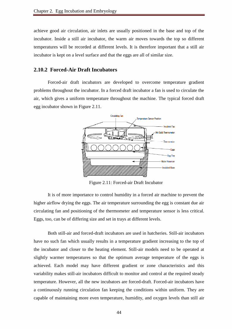
Chapter 2. Egg Incubation and Embryology
44
achieve good air circulation, air inlets are usually positioned in the base and top of the
incubator. Inside a still air incubator, the warm air moves towards the top so different
temperatures will be recorded at different levels. It is therefore important that a still air
incubator is kept on a level surface and that the eggs are all of similar size.
2.10.2 Forced-Air Draft Incubators
Forced-air draft incubators are developed to overcome temperature gradient
problems throughout the incubator. In a forced draft incubator a fan is used to circulate the
air, which gives a uniform temperature throughout the machine. The typical forced draft
egg incubator shown in Figure 2.11.
Figure 2.11: Forced-air Draft Incubator
It is of more importance to control humidity in a forced air machine to prevent the
higher airflow drying the eggs. The air temperature surrounding the egg is constant due air
circulating fan and positioning of the thermometer and temperature sensor is less critical.
Eggs, too, can be of differing size and set in trays at different levels.
Both still-air and forced-draft incubators are used in hatcheries. Still-air incubators
have no such fan which usually results in a temperature gradient increasing to the top of
the incubator and closer to the heating element. Still-air models need to be operated at
slightly warmer temperatures so that the optimum average temperature of the eggs is
achieved. Each model may have different gradient or zone characteristics and this
variability makes still-air incubators difficult to monitor and control at the required steady
temperature. However, all the new incubators are forced-draft. Forced-air incubators have
a continuously running circulation fan keeping the conditions within uniform. They are
capable of maintaining more even temperature, humidity, and oxygen levels than still air

Chapter 2. Egg Incubation and Embryology
45
incubators. Most of today’s large incubators are the forced-air type. They have fans that
circulate the air in the incubator and around the eggs.
The Table 2.3 shows the advantages and disadvantages of still air incubator and
forced draft incubator.
Table 2.3: The advantages and disadvantages the still-air and the forced-air incubator
Option Advantages Disadvantages
Still Air
Incubator Simple
Cheap
All eggs should be similar sizes
Only one level of hatching is
available
Temperature distribution isn’t
uniform
Forced air
incubator
Different egg sizes can be
hatched at different levels
Gives a uniform
temperature distribution
Allows the use different
types of sensor
Reliable
More complex
More cost
This project option involves the use of discrete components in easy, efficient and
cost effective egg incubator. Considering the advantage and disadvantage of these two
types of egg incubator Forced-draft incubator is preferred. That is why this project works
based on the forced-air draft incubation method.
Chapter 3 Design of a Microcontroller Based Forced Air Egg Incubator 3.1 Introduction In this project microcontroller based low cost incubator design, construct and
implement using locally available material and resource, to achieve a cost effective design.
It is able to incubate different types of eggs and it is a full function automatic forced air
egg incubator. The incubator automatically controls temperature, humidity, ventilation.
Also automatically eggs turning usually by slowly rocking them backwards and forwards
continuously. The incubator consists of three main parts. The first part is the incubator
casing. The casing has good physical properties to ensure good thermal isolation between
the interior room of the incubator and the external environment. The capacity of this
incubator is to incubate 120 eggs at a time. The second part is the automatic eggs tray
turning system. The last part is the microcontroller based controller used to measure and
control temperature, humidity, ventilation and eggs turning. The heart of the control unit is
the PIC16F877A which can determine the critical heat required and transfer function in
the incubator and regulate automatically.
3.2 Incubator Design Considerations and Implementation
Good design is essential for cost-effective incubation operation and design must
therefore incorporate food hygiene standards. The conditions provided to maintain
embryonic growth in the incubators are also ideal for the growth of bacteria and molds.
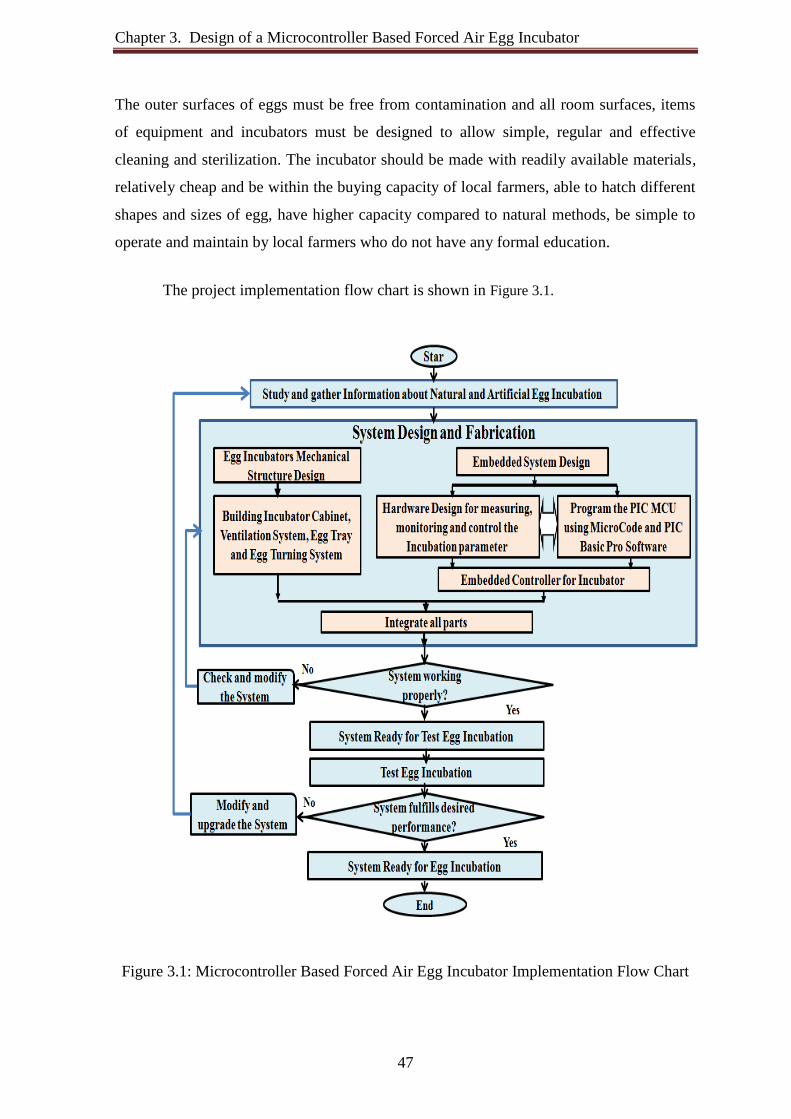
Chapter 3. Design of a Microcontroller Based Forced Air Egg Incubator
47
The outer surfaces of eggs must be free from contamination and all room surfaces, items
of equipment and incubators must be designed to allow simple, regular and effective
cleaning and sterilization. The incubator should be made with readily available materials,
relatively cheap and be within the buying capacity of local farmers, able to hatch different
shapes and sizes of egg, have higher capacity compared to natural methods, be simple to
operate and maintain by local farmers who do not have any formal education.
The project implementation flow chart is shown in Figure 3.1.
Figure 3.1: Microcontroller Based Forced Air Egg Incubator Implementation Flow Chart

Chapter 3. Design of a Microcontroller Based Forced Air Egg Incubator
48
Design and implementation of a Microcontroller Based Forced Air Egg Incubator
(MBFAEI) project development divided into three main design parts. There are: part 1 is
Mechanical structure design, part 2 is Embedded system design, this part is divided in to
two (a) Hardware design and (b) Software design. Then part 1 and part 2 are combined
together to perform the overall system operation and to provide proper embryonic
development environment and last part is test hatching to troubleshooting and upgrading
the system.
The microcontroller based forced air egg incubator have the following features; the
incubator has heating device, egg turning device, ventilation device and humidity device.
It has total four-heating bulbs with individual control and control parameter setup. This
forced air draft incubator has two circulating fans circulate the hot air and gives a uniform
temperature throughout the incubator. This helps to overcome the temperature gradients
throughout the incubator. Automatic ventilation system provides oxygen properly to
increase successful hatchability.
3.3 Mechanical Structure Design of the Incubator
The egg incubators mechanical structure design consist the development of
incubators enclosure where the eggs are sets to incubate successfully.
3.3.1 Incubator Casing
The first step for making the incubator was to build the incubator enclosure or
casing. The enclosure has good thermal isolation properties to keep the eggs warm and the
temperature constant in all parts of the incubator. A unique combined incubator was
designed that combines both the setting and hatching phase incorporate in a single unit to
save money and space by combining the two processes in a single unit.
The size of the incubator cabinet is taken depending on the number of 120 eggs to
be incubated and with necessary space to inspect the eggs. Incubator casing has the
following features: Durable wall and floor finishes and easy-to-clean. Wall surfaces have a
minimum joints and fastenings that impede effective cleaning. Microcontroller based
forced air egg incubator prototype is shown in Figure 3.2.

Chapter 3. Design of a Microcontroller Based Forced Air Egg Incubator
49
Figure 3.2: Microcontroller Based Forced Air Egg Incubator Prototype
A good quality material was used such as locally available hard plywood for
making casing of incubator. Wood is a good choice as long as it can be kept clean and free
of moisture. The softer wood will warp during the incubation process. The dimensions of
the incubator are given in table 3.1.
Table 3.1: Internal and External Dimensions of the Incubator
Dimensions Length (mm) Width (mm) Height (mm)
External 490 470 1280 Internal 440 420 1220
Thickness 50 50 60

Chapter 3. Design of a Microcontroller Based Forced Air Egg Incubator
50
Typical view of the incubator casing during construction process shown in Figure 3.3.
Figure 3.3: Typical View of the Incubator Casing during Construction Process
The performance of the incubator is directly related to the quality of its insulation.
Insulation is very important to keep the temperature constant. The incubator consists of a
wooden cabinet lined with multilayer insulating material as main ingredient (element) to
insulate against heat loss and system is properly lagged, thus leading to very small loss of
energy.
From inside to outside multilayer insulating layer are: First insulating layer is
formed by two coats of varnish allowing each coat to dry. The varnish prevents the hidden
ends are sealed against humidity and infiltration of disease organism and warping in the
high humidity of the incubator and allows washing the trays with disinfectant. Second
insulating layer is case is made of 19 mm plywood. Third insulating layer is made of 12
mm Polystyrene insulation sheet. The Figure 3.4 shows insulation layer in between
plywood. Forth insulating layer is again case is made of 19 mm plywood and fifth
insulating layer is again formed by two coats of varnish allowing each coat to dry. The
varnish prevents the hidden ends are sealed against outside weather. Bottom layer is
covered with Formica sheet.
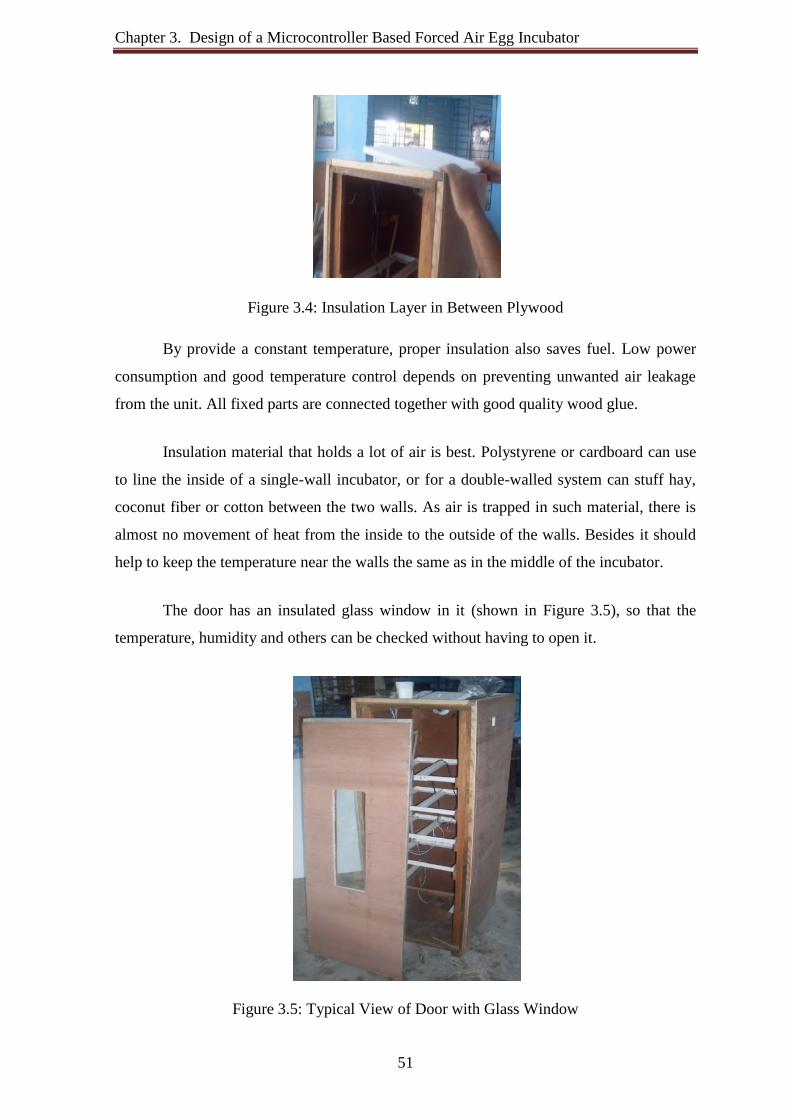
Chapter 3. Design of a Microcontroller Based Forced Air Egg Incubator
51
Figure 3.4: Insulation Layer in Between Plywood
By provide a constant temperature, proper insulation also saves fuel. Low power
consumption and good temperature control depends on preventing unwanted air leakage
from the unit. All fixed parts are connected together with good quality wood glue.
Insulation material that holds a lot of air is best. Polystyrene or cardboard can use
to line the inside of a single-wall incubator, or for a double-walled system can stuff hay,
coconut fiber or cotton between the two walls. As air is trapped in such material, there is
almost no movement of heat from the inside to the outside of the walls. Besides it should
help to keep the temperature near the walls the same as in the middle of the incubator.
The door has an insulated glass window in it (shown in Figure 3.5), so that the
temperature, humidity and others can be checked without having to open it.
Figure 3.5: Typical View of Door with Glass Window
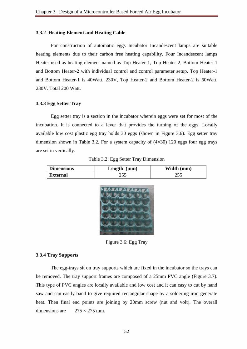
Chapter 3. Design of a Microcontroller Based Forced Air Egg Incubator
52
3.3.2 Heating Element and Heating Cable
For construction of automatic eggs Incubator Incandescent lamps are suitable
heating elements due to their carbon free heating capability. Four Incandescent lamps
Heater used as heating element named as Top Heater-1, Top Heater-2, Bottom Heater-1
and Bottom Heater-2 with individual control and control parameter setup. Top Heater-1
and Bottom Heater-1 is 40Watt, 230V, Top Heater-2 and Bottom Heater-2 is 60Watt,
230V. Total 200 Watt.
3.3.3 Egg Setter Tray
Egg setter tray is a section in the incubator wherein eggs were set for most of the
incubation. It is connected to a lever that provides the turning of the eggs. Locally
available low cost plastic egg tray holds 30 eggs (shown in Figure 3.6). Egg setter tray
dimension shown in Table 3.2. For a system capacity of (4×30) 120 eggs four egg trays
are set in vertically.
Table 3.2: Egg Setter Tray Dimension
Dimensions Length (mm) Width (mm) External 255 255
Figure 3.6: Egg Tray
3.3.4 Tray Supports
The egg-trays sit on tray supports which are fixed in the incubator so the trays can
be removed. The tray support frames are composed of a 25mm PVC angle (Figure 3.7).
This type of PVC angles are locally available and low cost and it can easy to cut by hand
saw and can easily band to give required rectangular shape by a soldering iron generate
heat. Then final end points are joining by 20mm screw (nut and volt). The overall
dimensions are 275 × 275 mm.

Chapter 3. Design of a Microcontroller Based Forced Air Egg Incubator
53
Figure 3.7: Tray Supports
There a gap of 305 mm between the top edges of the top tray and a gap of 440 mm
between the bottom edges of the trays the bottom walls, a gap of 65 mm between the
edges of the trays and side the walls and doors of the cabinet to allow air to circulate to
regulate the temperature inside the incubator. The tray supports are mounted in as a H
shaped horizontal support mount of the unit.
3.3.5 Egg Tray Turning Mechanism
The four egg tray supports are mounted properly so that, they rock together freely at
least 30° in each direction from horizontal. The system can adjust by loosen the screws or
add washers under them to keep the strap from bind with the supports.
A rocker arm attached to the right end of the top support tray extends thru the top of
the case and is bent to form a handle of sorts. The bend for the handle limits tray rocking
to the right, a clamp on the arm inside the case limits the travel of rockers to the left.
Figure 3.8: Egg Tray Turning Mechanism

Chapter 3. Design of a Microcontroller Based Forced Air Egg Incubator
54
DC gear motor with Egg tray turning mechanism used to rotate the egg tray at a
very low speed. It requires 12V/400mA DC power supply.
3.3.6 Egg Hatcher Tray
Hatcher tray is a tray with tray covers, where eggs were positioned after the 18th
day of incubation until they hatched. The external dimensions are 300 × 440 × 90 mm
PVC plastic tray. The hatching tray is 220mm above the bottom layer.
3.3.7 Circulating Fan
The circulating fan use for the purpose of circulating the hot air uniformly around
the chamber. Two DC brash less 12V, 0.6A fan is used to circulating the hot air from top
to bottom and bottom to top to make an air cycle inside the box. Fans are always kept on
during incubation.
3.3.8 Ventilation System
The developing embryo receives oxygen from the atmosphere and releases carbon-
dioxide; there is a ventilation hole with small fans to serves as heat and CO2 extractor and
the fan hole as oxygen in-let. Ventilation is provided automatically through holes pierced
in the sides of the incubator.
3.3.9 Water Supply and Water Pans
Water pans are placed at the bottom of the incubator to regulate humidity. Water
regulates the humidity inside the incubator. The fan blows warm air over a shallow pan of
water. The water evaporates, maintaining the high humidity but also cooling the air
somewhat. The surface area of the pan determines the humidity. For a higher humidity it
needs to increase the diameter of the evaporating pan.
This mechanical incubators imitate a hens natural brooding abilities by providing
an artificial micro-climate with the proper temperature, humidity, and ventilation, as well
as by allowing the eggs to be turned regularly.
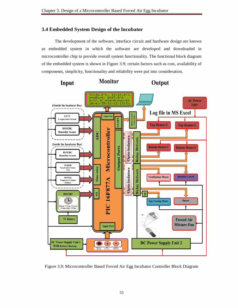
Chapter 3. Design of a Microcontroller Based Forced Air Egg Incubator
55
3.4 Embedded System Design of the Incubator
The development of the software, interface circuit and hardware design are known
as embedded system in which the software are developed and downloaded in
microcontroller chip to provide overall system functionality. The functional block diagram
of the embedded system is shown in Figure 3.9; certain factors such as cost, availability of
components, simplicity, functionality and reliability were put into consideration.
Figure 3.9: Microcontroller Based Forced Air Egg Incubator Controller Block Diagram

Chapter 3. Design of a Microcontroller Based Forced Air Egg Incubator
56
For measuring and automatic controlling temperature, humidity, ventilation and
egg turning, the Microcontroller Based Forced Air Egg Incubator Controller (MBFAEIC)
board designed and implemented, which is based on the PIC16F877A micro-controller,
DS1302 clock and the DS18B20, HSM20G, LM35 sensor. The input devices used inside
the incubator box are named as the Top Temperature sensor DS18B20 used to measure
temperature at top egg tray, the Bottom Temperature sensor DS18B20 used to measure
temperature at bottom egg tray, the incubator humidity sensor HSM-20G used to measure
incubation humidity and the real time clock/calendar used for getting real time to operate
egg tray turning motor timely and to keep incubation day. The input devices used outside
the incubator box are named as LM35 Temperature sensor used to measure outside room
temperature and humidity sensor hsm-20g used to measure outside room humidity. The
user interface consists of three push button named as Menu/Set, Up and Down are used to
set the temperature, humidity, Egg turning period , Clock setting and other parameter.
The design of this system includes two parts. These are the Electronic Hardware
Design and software development. For proper functionality of the system, these two parts
must agree with each other. The hardware and software design are discussed as follows:
3.4.1 Electronic Hardware Design The hardware unit consists of the following sub-unit:
The microcontroller unit, The Sensor Unit, The Real Time Clock calendar Unit, The Human Machine Interfacing unit, The Auto Saving Data Log in MS Excel Unit The Driver Unit and The Power Supply Unit.
These units are discussed below:
3.4.1.1 The Microcontroller Unit (MCU)
The microcontroller is a device which can make decision with the help of given
instruction. The microcontroller is called single chip microcomputer; it is a “one-chip-
solution”. In this forced air egg incubator implementation the microcontroller used to

Chapter 3. Design of a Microcontroller Based Forced Air Egg Incubator
57
controls, schedule and directs all the activities and behaviors based on the control program
written for it.
The 40 pin DIP microcontroller PIC16F877A form Microchip [51], satisfies the
criterion necessary for the Forced Air Egg Incubator application, used to control the
activities of all other sections. The Physical layout and Pin configuration PIC16F877A
microcontroller shown in Figure 3.10
(a) (b)
Figure 3.10: PIC16F877A Microcontroller (a) Physical Layout (b) Pin Configuration
The following basic criteria were considered in selecting this microcontroller for
the system. Ability to handle the task at hand efficiently and cost effectiveness; Maximum
operating speed the microcontroller can support; Power consumption; The number of I/O
pins and the easy of developing products around the chip, these include availability of
assembler, debugger, compiler and technical support Currently of the leading 8-bit
microcontrollers. The 8-bit microcontroller PIC16F877A was selected due to its good
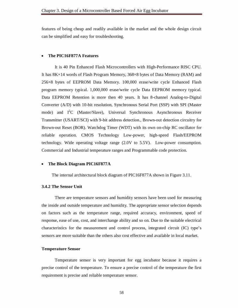
Chapter 3. Design of a Microcontroller Based Forced Air Egg Incubator
58
features of being cheap and readily available in the market and the whole design circuit
can be simplified and easy for troubleshooting.
The PIC16F877A Features
It is 40 Pin Enhanced Flash Microcontrollers with High-Performance RISC CPU.
It has 8K×14 words of Flash Program Memory, 368×8 bytes of Data Memory (RAM) and
256×8 bytes of EEPROM Data Memory. 100,000 erase/write cycle Enhanced Flash
program memory typical. 1,000,000 erase/write cycle Data EEPROM memory typical.
Data EEPROM Retention is more then 40 years. It has 8-channel Analog-to-Digital
Converter (A/D) with 10-bit resolution, Synchronous Serial Port (SSP) with SPI (Master
mode) and I2C (Master/Slave), Universal Synchronous Asynchronous Receiver
Transmitter (USART/SCI) with 9-bit address detection., Brown-out detection circuitry for
Brown-out Reset (BOR). Watchdog Timer (WDT) with its own on-chip RC oscillator for
reliable operation. CMOS Technology Low-power, high-speed Flash/EEPROM
technology. Wide operating voltage range (2.0V to 5.5V). Low-power consumption.
Commercial and Industrial temperature ranges and Programmable code protection.
The Block Diagram PIC16F877A
The internal architectural block diagram of PIC16F877A shown in Figure 3.11.
3.4.2 The Sensor Unit
There are temperature sensors and humidity sensors have been used for measuring
the inside and outside temperature and humidity. The appropriate sensor selection depends
on factors such as the temperature range, required accuracy, environment, speed of
response, ease of use, cost, and interchange ability and so on. Due to the suitable electrical
characteristics for the measurement and control process, integrated circuit (IC) type’s
sensors are more suitable than the others also cost effective and available in local market.
Temperature Sensor
Temperature sensor is very important for egg incubator because it requires a
precise control of the temperature. To ensure a precise control of the temperature the first
requirement is precise and reliable temperature sensor.
Chapter 3. Design of a Microcontroller Based Forced Air Egg Incubator
59
There are many types of sensors to measure the temperature, depending on the
accuracy, the temperature range, speed of response, thermal coupling, the environment and
the cost. The new generation semiconductor integrated circuit sensors used in this project.
Figure 3.11: PIC16F877A Internal Block Diagram
Integrated circuit temperature sensors are semiconductor devices fabricated in a
similar way to other semiconductor devices such as microcontrollers. A power supply is
required to operate these sensors.

Chapter 3. Design of a Microcontroller Based Forced Air Egg Incubator
60
Integrated circuit semiconductor temperature sensors can be divided into the following categories:
(a) Analog temperature sensors
(b) Digital temperature sensors
(a) Analog sensors are further divided into: Voltage output temperature sensors
Current output temperature sensors
Analog sensors can either be directly connected to measuring devices (such as
voltmeters), or A/D converters can be used to digitize the outputs so that they can be used
in computer based applications.
Voltage output temperature sensors
This sensor provides a voltage output signal which is proportional to the temperature
measured. LM35
LM35 can measure temperature more accurately than a using a thermistor. The
LM35 generates a higher output voltage than thermocouples and may not require that the
output voltage be amplified. LM35 is a 3-pin device and it has two versions and they both
provide a linear output voltage of 10mV/ºC [52]. The pin configuration of LM 35 shown
in Figure 3.12. The temperature range of the "CZ" version is -20 ºC to +120 ºC while the
"DZ" version only covers the range 0 ºC to +100 ºC. The LM35 does not require any
external calibration or trimming and maintains an accuracy of +/-0.4oC at room
temperature and +/- 0.8 oC over a range of 0oC to +100oC. The popular LM35DZ
temperature sensor can operate at the maximum supply voltage of +35 V, but the sensor is
normally operated at +5 V. When operated at +5 V, the supply current is around 80 µA.
The typical accuracy is ± 0.6 ºC at +25 ºC.
The output voltage is a direct indication of the temperature in 10mV/ ºC. An A/D
converter used to digitize the output voltage to interface with computer based applications.
The output voltage from the sensor converted to a 10-bit digital number using the internal

Chapter 3. Design of a Microcontroller Based Forced Air Egg Incubator
61
ADC of the PIC16F877A. Since the voltage to be measured by the ADC ranges from 0 to
1.0V that corresponds to temperature ranges from 0ºC to 100 °C.
Figure 3.12: LM35Voltage Output Temperature Sensor
ADC converts to mV: 1024 adc value means= 5000mV 1 adc value means= 5000mV/1024 ADCResult adc value means= (5000/1024* ADCResult) mV mV convert to º C: 10 mV is equivalent to 1º C 1 mV is equivalent to 1º C/10 (5000/1024* ADCResult) mV is equivalent to (5000/1024* ADCResult)*1/10º C = (0.48828125* ADCResult) º C
In this project one LM35DZ temperature sensor is used to measure the Incubation
room temperature.
(B) Digital Output Temperature Sensors
The digital output temperature sensors produce digital outputs which can be
interfaced directly to computer-based equipment. The outputs are usually non-standard
and the temperature can be extracted by using suitable algorithms. Digital temperature
sensors usually provide 1-wire or 3-wire interface, I2C bus, SPI bus, or some other to the
outside world.

Chapter 3. Design of a Microcontroller Based Forced Air Egg Incubator
62
DS18B20 DS18B20 is direct-to-digital temperature sensor which also incorporates digitally
programmable thermostat outputs [53]. The resolution of the temperature sensor is user-
configurable to 9, 10, 11, or 12 bits, corresponding to increments of 0.5°C, 0.25°C,
0.125°C, and 0.0625°C, respectively. The default resolution at power-up is 12-bit. The
DS18B20 communicates over a 1-Wire bus that by definition requires only one data line
(and ground) for communication with a central microprocessor. It has an operating
temperature range of -55°C to +125°C and is accurate to ±0.5°C over the range of -10°C
to +85°C. For continuous control of the temperature, the temperature sensor DS18B20 is
suitable for precisely measure temperatures in wet environments.
Pin assignment, pin description and block diagram of DS18B20 shown in Figure
3.13, Figure 3.14 and Figure 3.15.
Figure 3.13: DS18B20 Digital Output Temperature Sensors
Figure 3.14: DS18B20 Detail Pin Description
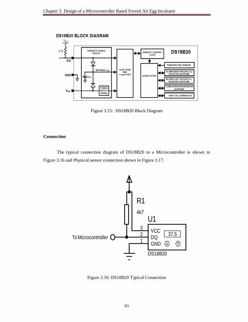
Chapter 3. Design of a Microcontroller Based Forced Air Egg Incubator
63
Figure 3.15: DS18B20 Block Diagram
Connection
The typical connection diagram of DS18B20 to a Microcontroller is shown in
Figure 3.16 and Physical sensor connection shown in Figure 3.17.
Figure 3.16: DS18B20 Typical Connection
37.5DQ2 VCC3
GND1
U1
DS18B20
R14k7
To Microcontroller

Chapter 3. Design of a Microcontroller Based Forced Air Egg Incubator
64
Figure 3.17: Physical Sensor Connection
DS18B20 Memory.
Scratchpad is 9 bytes of SRAM that organized as figure shown in Figure 3.18. The
first two bytes (byte 0 and byte 1) are read-only memory that contain the LSB and the
MSB of the temperature register. Bytes 2 and 3 provide access to TH and TL registers.
Byte 4 is a configuration register. Bytes 5,6 and 7 are reserved. Byte 8 is read-only and
contains CRC code (cyclic redundancy check) for byte 0 through byte 7 of the scratchpad.
Figure 3.18: DS18B20 Memory Map
The output temperature data from DS18B20 is calibrated in degree centigrade and
the default resolution at power up is 12-bit. The temperature register format shown in
Figure 3.19, where as sign bits (S) indicate if the temperature is positive (S=0) or negative
(S=1).

Chapter 3. Design of a Microcontroller Based Forced Air Egg Incubator
65
Figure 3.19: Temperature/Data Relationship Programming steps of DS18B20 To access the DS18B20's data, 3 steps sequence as follows is need. 1. Initialization: All transactions on the 1-wire bus begin with an initialization sequence.
It consists of a reset pulse transmitted by the bus master followed by presence pulse
transmitted by the slave. Timing for the reset and presence pulse is shown in Figure 3.20.
Figure 3.20: DS18B20 Initialization Timing
2. Issue a ROM Command: Issue a ROM command after the bus master has detected a
presence pulse. ROM commands are : Search ROM[F0h], Read ROM[33h], Match
ROM[55h], Skip ROM[CCh] and Alarm Search[ECh].

Chapter 3. Design of a Microcontroller Based Forced Air Egg Incubator
66
3. Issue a DS18B20 Function Command: Issue a DS18B20 function command after a
ROM command. A ROM command is to select which DS18B20 that the master wants to
communicate with. A function command allows the master to read and to write from the
DS18B20's scratchpad, etc. DS18B20 function commands are: Convert T[44h], Write
Scratchpad[4Eh], Read Scratchpad[BEh], Copy Scratchpad[48h], Recall E2[B8h], and
Read Power Supply[B4h]. It is very important to follow this sequence every time the
DS18B20 is accessed. Exceptions to this rule are Search ROM[F0] and Alarm Search[EC]
commands. The master must return to step 1 after issue either of those ROM commands.
In this project two DS18B20 temperature sensor are used to measure the inside
temperature of egg incubator.
Humidity Sensor
Absolute Humidity is the mass of water vapor divided by the mass of dry air in a
volume of air at a given temperature. The hotter the air is, the more water it can contain.
Relative humidity is the ratio of the current absolute humidity to the highest possible
absolute humidity which depends on the current air temperature.
A reading of 100 % relative humidity means that the air is totally saturated with
water vapor and cannot hold any more, creating the possibility of rain. This doesn't mean
that the relative humidity must be 100 percent in order for it to rain. It must be 100 percent
where the clouds are forming, but the relative humidity near the ground could be much
less.
Due to the suitable electrical characteristics for the measurement and control
process, integrated circuit (IC) type’s humidity sensors are more suitable than the others.
HSM-20G
HSM-20G is a Humidity and Temperature sensor [54]. It converts the relative
humidity to standard voltage output. Its storage relative humidity (RH) Range 0 to 99%
RH, measurement accuracy ±5% RH. Output voltage range DC 1-3.19V. Input voltage
range is DC 5.0±0.2V, Operating Current (Maximum) is 2mA.

Chapter 3. Design of a Microcontroller Based Forced Air Egg Incubator
67
The HSM-20G humidity sensor shown in Figure 3.21 are cost effective (cost
around 300 taka) and available in local market.
(a) (b)
Figure 3.21: HSM20G Humidity Sensor (a) Front View, (b) Back View
HSM-20G is an analog sensor. HSM-20G, datasheet have given output voltage
data from the humidity sensor for certain relative humidity values and also have a plotted
graph too. Same with the Temperature Sensor this sensor too is connected to an ADC
(analog to digital converter) in order to get the output in digital.
Typical Response of HSM-20G at 25ºC
The typical response of Relative humidity verses output voltage at 25ºC of HSM-
20G shown in Figure 3.22(a).
(a) Relative Humidity Verses Output Voltage Plot [54] (b) Linear Equation for Relative Humidity, % RH
Figure 3.22: Relative Humidity Response of HSM-20G

Chapter 3. Design of a Microcontroller Based Forced Air Egg Incubator
68
Standard Characteristics
The module of HSM-20G is essential for those applications where the relative
humidity can be converted to standard voltage output. The Relative humidity verses output
voltage of HSM-20G shown in Table 3.3[54]. By using Table 3.3 the suitable linear
equation for determine the Relative Humidity from the output voltage of HSM-20G is
%RH = (30.85 × Output Voltage - 11.50) shown in Figure 3.22 (b).
Table 3.3: Relative Humidity Verses Output Voltage Relation
Relative
Humidity,
%RH
10
20
30
40
50
60
70
80
90
Output
Voltage,
V
0.74V
0.95V
1.31V
1.68V
2.02V
2.37V
2.69V
2.99V
3.19V
In order to use this sensor, a connector cable was build to connect the sensor to main
MBFAEIC control board. The Physical connection of sensor HSM20G shown in Figure
3.23, the 3-pin header was connected to the circuit required such that:
(-) negative pin connects to GND
(+) positive pin connects to Vcc
H (humidity sensor) pin connects to ADC.
Figure 3.23: Physical Sensor Connection (HSM20G)
For continuous control of the humidity, the humidity sensor hsm-20g is the right choice and suitable for it’s precisely measure humidity. One hsm-20g humidity sensor is used to measure the current humidity inside the egg incubator and another humidity sensor hsm-20g is used to measure the incubation room humidity.

Chapter 3. Design of a Microcontroller Based Forced Air Egg Incubator
69
3.4.3 The Real Time Clock (RTC) Unit The Real Time Clock (RTC) unit provides real time measure which the
microcontroller used to maintain the automatic schedule egg turning system and to keep
incubation period of the egg.
The DS1302 real time clock was used for this unit [55]. It is a trickle-charge
timekeeping chip contains a real-time clock/calendar and 31 bytes of 31 x 8 Battery-
Backed General-Purpose static RAM [56]. The real-time clock/calendar provides seconds,
minutes, hours, day, date, month, and year information with Leap-Year Compensation
Valid Up to 2100. The end of the month date is automatically adjusted for months with
fewer than 31 days, including corrections for leap year. The clock operates in either the
24-hour or 12-hour format with an AM/PM indicator. It can operate in full operation at
2.0V to 5.5V. The DS1302 pin diagram shown in Figure 3.24.
Figure 3.24: DS1302 Pin Diagram
It communicates with PIC16F877A microcontroller via synchronous serial
communication. Only three wires are used to communicate with the clock/RAM are CE,
I/O (data line), and SCLK (serial clock). Data are transferred to and from the clock/RAM
in a Multiple-Byte Burst of up to 31 bytes for Read or Write of Clock or RAM Data. PIN DESCRIPTION
PIN NAME FUNCTION 1
VCC2
Primary Power-Supply Pin in Dual Supply Configuration. VCC1 is connected to a backup source to maintain the time and date in the absence of primary power. The DS1302 operates from the larger of VCC1 or VCC2. When VCC2 is greater than VCC1 + 0.2V, VCC2 powers the DS1302. When VCC2 is less than VCC1, VCC1 powers the DS1302.
2 X1
Connections for Standard 32.768kHz Quartz Crystal. 3 X2

Chapter 3. Design of a Microcontroller Based Forced Air Egg Incubator
70
4
GND
Ground 5
CE or
RST
Input. CE signal must be asserted high during a read or a write. This pin has an internal 40kΩ pull-down resistor to ground.
6 I/O
Input/Push-Pull Output. The I/O pin is the bidirectional data pin for the 3-wire interface. This pin has an internal 40kΩ pull-down resistor to ground.
7 SCLK
Input. SCLK is used to synchronize data movement on the serial
interface. This pin has an internal 40kΩ pull-down resistor to ground.
8 VCC1
Low-Power Operation in Single Supply and Battery-Operated Systems and Low-Power Battery Backup. In systems using the trickle charger, the rechargeable energy source is connected to this pin.
Uninterrupted Power
A lithium battery was used to provide a source of alternative power supply to the
RTC. It is used to maintain accurate time even when there is no power supply to the
system. A supper capacitor can be used in case of uninterrupted power. The capacitor will
be charged through the DS1302 chip. The charge (true) method will charge the capacitor
which works only for a SuperCap.
Figure 3.25: Wiring Diagram for the DS1302
RST
RST
SCLKDTA
DTASCLK
RA0/AN02
RA1/AN13
RA2/AN2/VREF-4
RA4/T0CKI6
RA5/AN4/SS7
RE0/AN5/RD8
RE1/AN6/WR9
RE2/AN7/CS10
OSC1/CLKIN13
OSC2/CLKOUT14
RC1/T1OSI/CCP2 16
RC2/CCP1 17
RC3/SCK/SCL 18
RD0/PSP0 19
RD1/PSP1 20
RB7/PGD 40RB6/PGC 39RB5 38RB4 37RB3/PGM 36
RB2 35RB1 34RB0/INT 33
RD7/PSP7 30RD6/PSP6 29RD5/PSP5 28RD4/PSP4 27RD3/PSP3 22RD2/PSP2 21
RC7/RX/DT 26RC6/TX/CK 25RC5/SDO 24RC4/SDI/SDA 23
RA3/AN3/VREF+5
RC0/T1OSO/T1CKI 15
MCLR/Vpp/THV1
PIC16F877A
PIC16F877
33k
VCC
X1CRYSTAL
C5
100n
C6
100n
T_out_HSM20GH_out_HSM20G
LM35_1H_in_HSM20G
C3100n
2.2k
RST 5
SCLK 7
I/O 6
X12
X23
VCC1 8
VCC2 1
U_DS1302
DS1302
12
BAT13.2V
12
XT1
XT_PCB
VCC
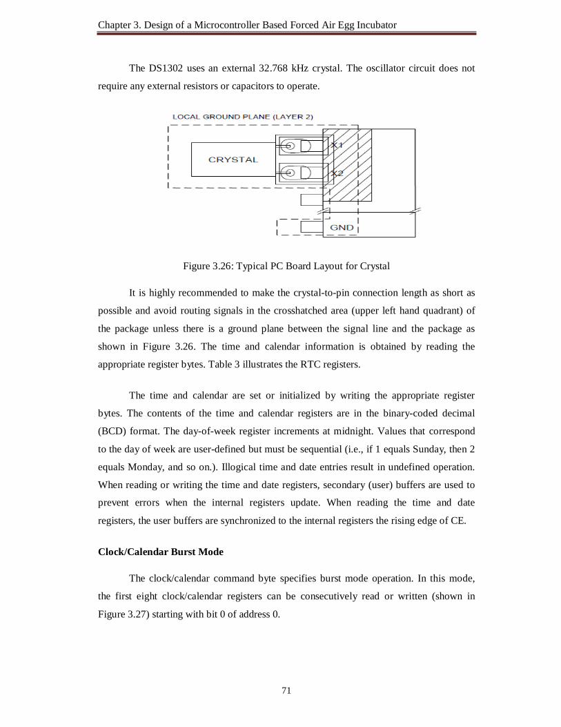
Chapter 3. Design of a Microcontroller Based Forced Air Egg Incubator
71
The DS1302 uses an external 32.768 kHz crystal. The oscillator circuit does not
require any external resistors or capacitors to operate.
Figure 3.26: Typical PC Board Layout for Crystal
It is highly recommended to make the crystal-to-pin connection length as short as
possible and avoid routing signals in the crosshatched area (upper left hand quadrant) of
the package unless there is a ground plane between the signal line and the package as
shown in Figure 3.26. The time and calendar information is obtained by reading the
appropriate register bytes. Table 3 illustrates the RTC registers.
The time and calendar are set or initialized by writing the appropriate register
bytes. The contents of the time and calendar registers are in the binary-coded decimal
(BCD) format. The day-of-week register increments at midnight. Values that correspond
to the day of week are user-defined but must be sequential (i.e., if 1 equals Sunday, then 2
equals Monday, and so on.). Illogical time and date entries result in undefined operation.
When reading or writing the time and date registers, secondary (user) buffers are used to
prevent errors when the internal registers update. When reading the time and date
registers, the user buffers are synchronized to the internal registers the rising edge of CE.
Clock/Calendar Burst Mode
The clock/calendar command byte specifies burst mode operation. In this mode,
the first eight clock/calendar registers can be consecutively read or written (shown in
Figure 3.27) starting with bit 0 of address 0.
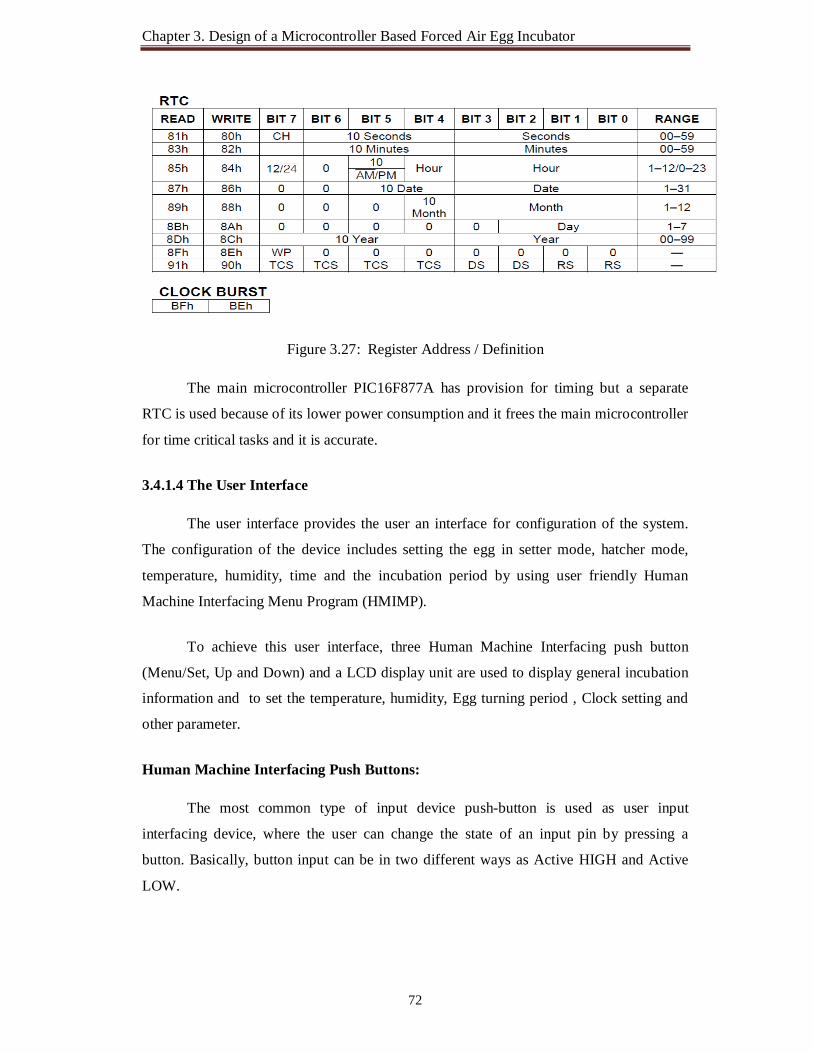
Chapter 3. Design of a Microcontroller Based Forced Air Egg Incubator
72
Figure 3.27: Register Address / Definition
The main microcontroller PIC16F877A has provision for timing but a separate
RTC is used because of its lower power consumption and it frees the main microcontroller
for time critical tasks and it is accurate.
3.4.1.4 The User Interface
The user interface provides the user an interface for configuration of the system.
The configuration of the device includes setting the egg in setter mode, hatcher mode,
temperature, humidity, time and the incubation period by using user friendly Human
Machine Interfacing Menu Program (HMIMP).
To achieve this user interface, three Human Machine Interfacing push button
(Menu/Set, Up and Down) and a LCD display unit are used to display general incubation
information and to set the temperature, humidity, Egg turning period , Clock setting and
other parameter.
Human Machine Interfacing Push Buttons:
The most common type of input device push-button is used as user input
interfacing device, where the user can change the state of an input pin by pressing a
button. Basically, button input can be in two different ways as Active HIGH and Active
LOW.

Chapter 3. Design of a Microcontroller Based Forced Air Egg Incubator
73
The Human Machine Interfacing Push Buttons are connected as Active HIGH
configurations. In this configuration the button is connected between the supply voltage
and the port pin. A resistor (this is also called a pull-down resistor) is connected between
the port pin and ground. Normally, the port pin is at logic 0. When the button is pressed
the port pin goes to the supply voltage which is logic 1.When switch S1 is open, there is
practically no current flowing through the pull-down resistors. Therefore, the voltage at
point A is the same as ground (0 volts), since there is no voltage drop across pull-down
resistors. The PIC pin is held to LOW (0 volts) until the switch is closed, at which point
the PIC pin goes HIGH (+5 volts).
Figure 3.28: Human Machine Interfacing Push Buttons Control Circuitry
If nothing is connected to the input pin, the voltage at the input is considered
floating, i.e., some unknown voltage between 0 and +5 volts. Pull-down resistor will
allow the pin to keep a steady state at 0 volts until switch S1 is closed.
D7
D6 D7
D5
D4
ERS
D6D5D4E
RS
MENU
DOWNUP
DOWN
UPMENU
RA0/AN02
RA1/AN13
RA2/AN2/VREF-4
RA4/T0CKI6
RA5/AN4/SS7
RE0/AN5/RD8
RE1/AN6/WR9
RE2/AN7/CS10
OSC1/CLKIN13
OSC2/CLKOUT14
RC1/T1OSI/CCP2 16
RC2/CCP1 17
RC3/SCK/SCL 18
RD0/PSP0 19
RD1/PSP1 20
RB7/PGD 40RB6/PGC 39RB5 38RB4 37RB3/PGM 36RB2 35RB1 34RB0/INT 33
RD7/PSP7 30RD6/PSP6 29RD5/PSP5 28RD4/PSP4 27RD3/PSP3 22RD2/PSP2 21
RC7/RX/DT 26RC6/TX/CK 25RC5/SDO 24RC4/SDI/SDA 23
RA3/AN3/VREF+5
RC0/T1OSO/T1CKI 15
MCLR/Vpp/THV1
PIC16F877A
PIC16F877
33k
VCC
X1CRYSTAL
C5
100n
C6
100n
RB0DQ1
T_out_HSM20GH_out_HSM20G
LM35_1H_in_HSM20G
C3100n
2.2k
D7
14D
613
D5
12D
411
D3
10D
29
D1
8D
07
E6
RW5
RS
4
VSS
1
VDD
2
VEE
3
A15
K16
LCD1LCD_PCB
VCC
MENU DownUP 100n
> <
10k 10k 10k
LCD Display
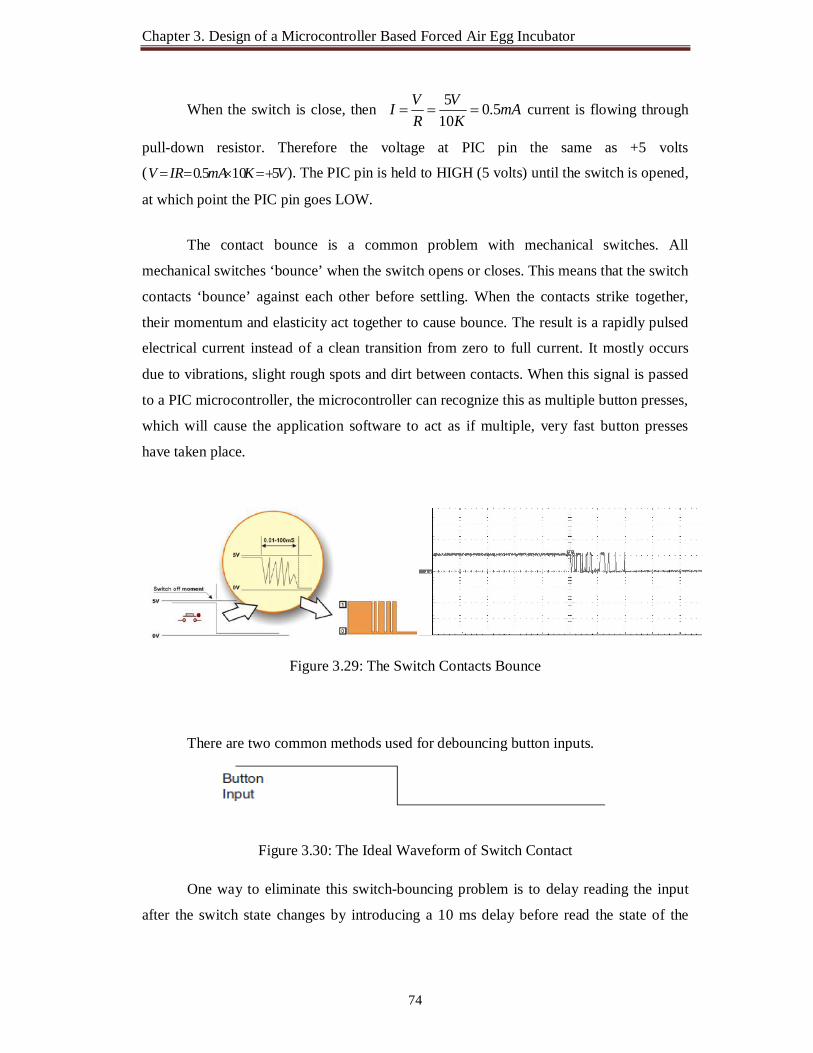
Chapter 3. Design of a Microcontroller Based Forced Air Egg Incubator
74
When the switch is close, then mAK
VRVI 5.0
105
current is flowing through
pull-down resistor. Therefore the voltage at PIC pin the same as +5 volts
( VKmAIRV 5105.0 ). The PIC pin is held to HIGH (5 volts) until the switch is opened,
at which point the PIC pin goes LOW.
The contact bounce is a common problem with mechanical switches. All
mechanical switches ‘bounce’ when the switch opens or closes. This means that the switch
contacts ‘bounce’ against each other before settling. When the contacts strike together,
their momentum and elasticity act together to cause bounce. The result is a rapidly pulsed
electrical current instead of a clean transition from zero to full current. It mostly occurs
due to vibrations, slight rough spots and dirt between contacts. When this signal is passed
to a PIC microcontroller, the microcontroller can recognize this as multiple button presses,
which will cause the application software to act as if multiple, very fast button presses
have taken place.
Figure 3.29: The Switch Contacts Bounce
There are two common methods used for debouncing button inputs.
Figure 3.30: The Ideal Waveform of Switch Contact
One way to eliminate this switch-bouncing problem is to delay reading the input
after the switch state changes by introducing a 10 ms delay before read the state of the
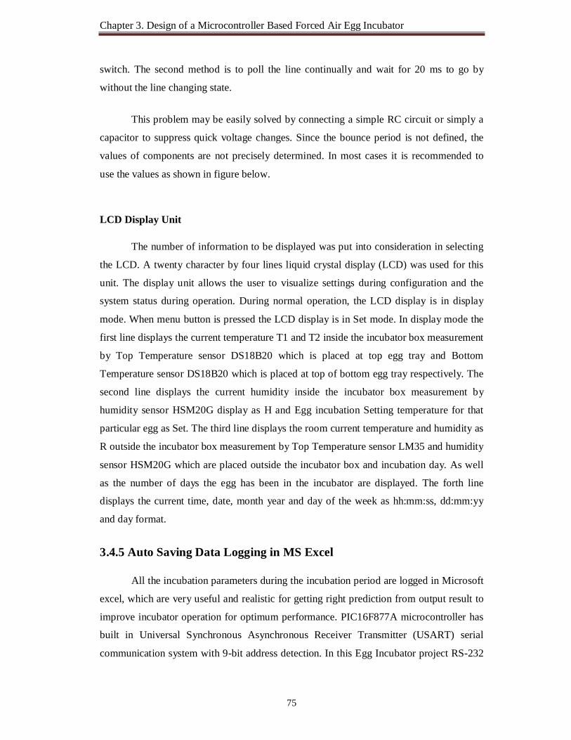
Chapter 3. Design of a Microcontroller Based Forced Air Egg Incubator
75
switch. The second method is to poll the line continually and wait for 20 ms to go by
without the line changing state.
This problem may be easily solved by connecting a simple RC circuit or simply a
capacitor to suppress quick voltage changes. Since the bounce period is not defined, the
values of components are not precisely determined. In most cases it is recommended to
use the values as shown in figure below.
LCD Display Unit
The number of information to be displayed was put into consideration in selecting
the LCD. A twenty character by four lines liquid crystal display (LCD) was used for this
unit. The display unit allows the user to visualize settings during configuration and the
system status during operation. During normal operation, the LCD display is in display
mode. When menu button is pressed the LCD display is in Set mode. In display mode the
first line displays the current temperature T1 and T2 inside the incubator box measurement
by Top Temperature sensor DS18B20 which is placed at top egg tray and Bottom
Temperature sensor DS18B20 which is placed at top of bottom egg tray respectively. The
second line displays the current humidity inside the incubator box measurement by
humidity sensor HSM20G display as H and Egg incubation Setting temperature for that
particular egg as Set. The third line displays the room current temperature and humidity as
R outside the incubator box measurement by Top Temperature sensor LM35 and humidity
sensor HSM20G which are placed outside the incubator box and incubation day. As well
as the number of days the egg has been in the incubator are displayed. The forth line
displays the current time, date, month year and day of the week as hh:mm:ss, dd:mm:yy
and day format.
3.4.5 Auto Saving Data Logging in MS Excel
All the incubation parameters during the incubation period are logged in Microsoft
excel, which are very useful and realistic for getting right prediction from output result to
improve incubator operation for optimum performance. PIC16F877A microcontroller has
built in Universal Synchronous Asynchronous Receiver Transmitter (USART) serial
communication system with 9-bit address detection. In this Egg Incubator project RS-232

Chapter 3. Design of a Microcontroller Based Forced Air Egg Incubator
serial communication use to send and receive data between a PIC microcontroller and a
PC. By using RS232 to USB converter incubation data are store in laptop during test
hatching.
A MAX 232 was used to provide voltage matching of the different types of logic
used in the microcontroller and those in the P C, because of voltage level differences of
the devices. The Max 232 is a 16 pin dip IC that is used to convert CMOS voltages to TTL
voltages. An example of a signal on both sides of a MAX232 converter chip:
Figure 3.31: Signal as it Leaves the PIC Pin (The PIC Side of the MAX232)
Figure 3.32: Signal on an RS232 Line (The PC Side of the MAX232)
Figure 3.33: RS232 Data Logger Circuit A straight-through cable is used to connect a PC to a remote egg incubator. 3.4.1.6 The Driver Unit
The microcontroller cannot directly drive the relays to which the actuators are
connected as it could not supply the required current needed to drive the relay. In

Chapter 3. Design of a Microcontroller Based Forced Air Egg Incubator
77
designing the current driver the switching current for the relays was put into consideration.
The PIC Microcontroller output pins can either act as a source of current or as a sink for
current to drive electronic devices. The maximum output current sunk or source by any
I/O pin is 25mA.
The transistor connects as the High Active Switch (Logical High) also known as
low side switch using NPN transistor.
Buzzer and Relay interface:
Figure 3.34: Buzzer Circuit
Figure 3.35: Interfacing Relay with Microcontroller
Q_BZBC547
R_BZ1k
BZREX
T_v
BD1351k
REL
AY1
(H1)
12
+12V
123
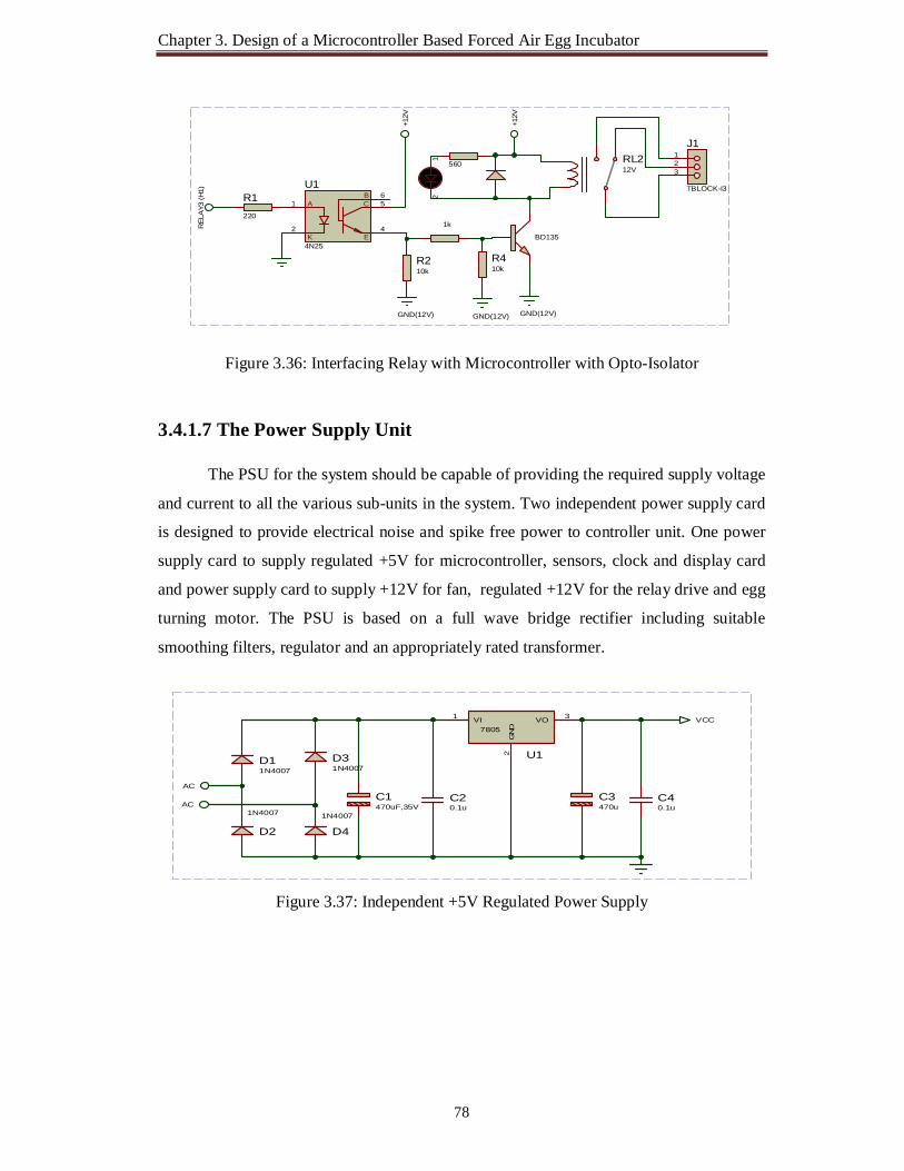
Chapter 3. Design of a Microcontroller Based Forced Air Egg Incubator
78
Figure 3.36: Interfacing Relay with Microcontroller with Opto-Isolator
3.4.1.7 The Power Supply Unit
The PSU for the system should be capable of providing the required supply voltage
and current to all the various sub-units in the system. Two independent power supply card
is designed to provide electrical noise and spike free power to controller unit. One power
supply card to supply regulated +5V for microcontroller, sensors, clock and display card
and power supply card to supply +12V for fan, regulated +12V for the relay drive and egg
turning motor. The PSU is based on a full wave bridge rectifier including suitable
smoothing filters, regulator and an appropriately rated transformer.
Figure 3.37: Independent +5V Regulated Power Supply
BD135
1k
GND(12V)
560
12
+12V
A
K
C
E
B1
2 4
56
U1
4N25
R1220
GND(12V)
+12V
RL212V
R210k
R410k
GND(12V)
123
J1
TBLOCK-I3
REL
AY3
(H1)
D11N4007
D2
1N4007
D31N4007
D4
1N4007
C1470uF,35V
C20.1u
VI1 VO 3
GND
2 U1
7805
C3470u
C40.1u
VCC
AC
AC

Chapter 3. Design of a Microcontroller Based Forced Air Egg Incubator
79
Figure 3.38: Independent +12V Regulated Power Supply
Beside this power supply computer ATX power supply also suitable and used in
this project.
In order to enable the PIC16F877A microcontroller to operate properly it provide
Power Supply, Reset Signal and Clock Signal is called minimum hardware requirements
of PIC microcontroller. The device operates at 8MHz, so a high execution speed achieved
with a single chip microcontroller unit.
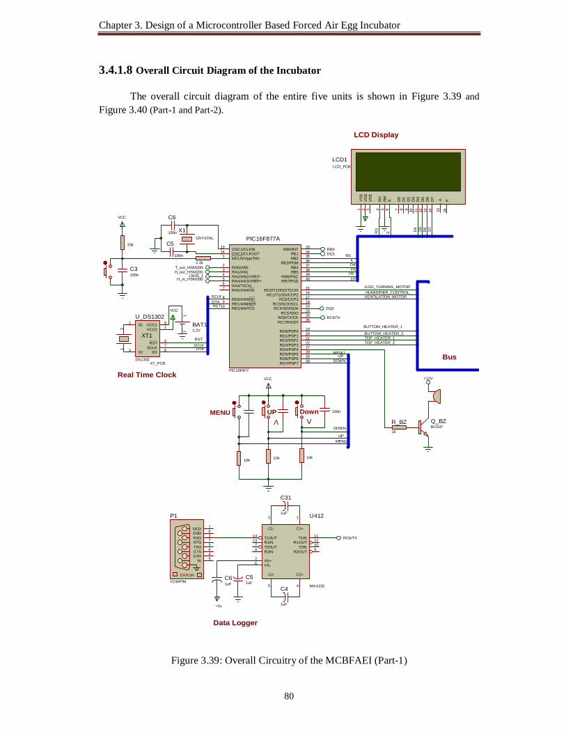
Chapter 3. Design of a Microcontroller Based Forced Air Egg Incubator
80
3.4.1.8 Overall Circuit Diagram of the Incubator The overall circuit diagram of the entire five units is shown in Figure 3.39 and
Figure 3.40 (Part-1 and Part-2).
Figure 3.39: Overall Circuitry of the MCBFAEI (Part-1)
D7
D6 D7
D5
D4
ERS
D6D5D4E
RS
RST
RST
SCLKDTA
DTASCLK
MENU
DOWNUP
DOWN
UPMENU
BUTTOM_HEATER_1
BUTTOM_HEATER_2TOP_HEATER_1TOP_HEATER_2
EGG_TURNING_MOTORHUMIDIFIER_CONTROL
VENTILATION_MOTOR
RA0/AN02
RA1/AN13
RA2/AN2/VREF-4
RA4/T0CKI6
RA5/AN4/SS7
RE0/AN5/RD8
RE1/AN6/WR9
RE2/AN7/CS10
OSC1/CLKIN13
OSC2/CLKOUT14
RC1/T1OSI/CCP2 16
RC2/CCP1 17
RC3/SCK/SCL 18
RD0/PSP0 19
RD1/PSP1 20
RB7/PGD 40RB6/PGC 39RB5 38RB4 37RB3/PGM 36RB2 35RB1 34RB0/INT 33
RD7/PSP7 30RD6/PSP6 29RD5/PSP5 28RD4/PSP4 27RD3/PSP3 22RD2/PSP2 21
RC7/RX/DT 26RC6/TX/CK 25RC5/SDO 24RC4/SDI/SDA 23
RA3/AN3/VREF+5
RC0/T1OSO/T1CKI 15
MCLR/Vpp/THV1
PIC16F877A
PIC16F877
33k
VCC
X1CRYSTAL
C5
100n
C6
100n
RB0DQ1
RC6/Tx
T_out_HSM20GH_out_HSM20G
LM35_1H_in_HSM20G
C3100n
2.2k
D7
14D
613
D5
12D
411
D3
10D
29
D1
8D
07
E6
RW5
RS
4
VSS
1
VDD
2
VEE
3
A15
K16
LCD1LCD_PCB
RST 5
SCLK 7
I/O 6
X12
X23
VCC1 8
VCC2 1
U_DS1302
DS1302
12
BAT13.2V
12
XT1
XT_PCB
VCC
VCC
MENU DownUP 100n
> <
10k 10k 10k
RC6/TXT1IN 11
R1OUT 12
T2IN 10
R2OUT 9
T1OUT14
R1IN13
T2OUT7
R2IN8
C2+
4
C2-
5
C1+
1
C1-
3
VS+2
VS-6
U412
MAX232
C31
1uF
C4
1uF
C61uF
+5v
C51uF
ERROR
TXD 3
RXD 2
CTS 8
RTS 7
DSR 6
DTR 4
DCD 1
RI 9
P1
COMPIM
Q_BZBC547
R_BZ1k
+12V
Bus
DQ2
Data Logger
Real Time Clock
LCD Display

Chapter 3. Design of a Microcontroller Based Forced Air Egg Incubator
81
Figure 3.40: Overall Circuitry of the MCBFAEI (Part-2)
TOP_HEATER_2
BUTTOM_HEATER_2
EGG_TURNING_MOTOR
TOP_HEATER_1
BUTTOM_HEATER_1
VENTILATION_MOTOR
HUMIDIFIER_CONTROL
37.5DQ2 VCC3
GND1
U1
DS18B20
R14k7
VCC
DQ1
TOP_HEAT_SENSOR
36.7DQ2VCC3
GND1
U112
DS18B20
R1124k7
VCC
BOTTOM_HEAT_SENSOR
VCC
H
H
BD1351k
12
+12V
BD135
1k
12
+12V
Heater
T
OV1OVEN
Heater
T
OV2OVEN
BD1351k
560 R
12
+12V
BD135
1k
12
+12V
Heater
T
OV1OVEN
Heater
T
OV2OVEN
AC 230 Volt (L)
Heater
T
OV3OVEN
BD1351k
12
+12V
BD135
1k
12
+12V
BD1351k
12
+12V +1
2V
+12V
H_IN_HSM20G
Bus
DQ2
EGG INCUBATOR
EGG INCUBATOR
VENTILATION FAN
TOP_HEATER_1 TOP_HEATER_2
BUTTOM_HEATER_2BUTTOM_HEATER_1 HUMIDIFIER_CONTROL
Busses Mode
VCC
HH_OUT_HSM20G
Room Humidity Sensor
LM35_1
37.5
3
1
VOUT2
U4LM35
Room Temperature Sensor
EGG INCUBATOR
EGG INCUBATOR
Incubator Humidity Sensor
Egg Turning Motor

Chapter 3. Design of a Microcontroller Based Forced Air Egg Incubator
82
3.4.1.9 IR Remote Control for Egg Turning System
IR remote control also use for operating the egg turning mechanism. For this
purpose SIRC Protocol based IR transmitter and receiver is designed in this project works
using PIC microcontroller. SIRC Protocol is selected for this project work because of
Sony use SIRC Protocol and Sony remote control(Rx) are locally available very low cost
approximately 40 taka to 100 taka. To make a unique egg turning mechanism SIRC
Protocol based IR transmitter with device code 4 is designed also receiver circuit is
designer for a device code 4.
The PIC microcontroller PIC12F675 used for IR remote control egg turning system
has built-in oscillator circuits and they do not require any external timing components. The
built-in oscillator is usually set to operate at 4 MHz and is selected during the
programming of the device. A factory-calibrated oscillator constant is loaded into the last
location of the memory. By copying this constant value into the oscillator register we can
have a more accurate 4 MHz clock frequency for our microcontroller.
Figure 3.41: IR Remote Control Transmitter and Receiver System SIRC Protocol
Figure 3.42: Modulation of SIRC Protocol

Chapter 3. Design of a Microcontroller Based Forced Air Egg Incubator
83
The SIRC protocol uses a pulse width encoding of the bits. The pulse representing
a logical “1” is a 1.2ms long burst of the 38kHz to 40kHz carrier, while the burst width for
a logical “0” is 0.6ms long. All bursts are separated by a 0.6ms long space interval. The
recommended carrier duty-cycle is 1/4 or 1/3.
Features
5-bit address and 7-bit command length (12-bit protocol)
Pulse width modulation
Carrier frequency of 38kHz to 40kHz
Bit time of 1.2ms or 0.6ms
Figure 3.43: SIRC Protocol Signal Pattern
The picture above shows a typical pulse train of the SIRC protocol. With this
protocol the LSB is transmitted first. The start burst is always 2.4ms wide, followed by a
standard space of 0.6ms. Apart from signaling the start of a SIRC message this start burst
is also used to adjust the gain of the IR receiver. Then the 7-bit Command is transmitted,
followed by the 5-bit Device address. In this case Address 1 and Command 19 are
transmitted. Commands are repeated every 45ms (measured from start to start) for as long
as the key on the remote control is held down.

Chapter 3. Design of a Microcontroller Based Forced Air Egg Incubator
84
3.4.2 Software Development
Software Development deals with developing of software for the control of
parameters such as temperature, humidity, ventilation and eggs turning of incubator to
provide proper embryonic development environment. Software is an integral part the
control system; it interacts with hardware to carry out different functions which are
responsible for the control of parameters.
Flowcharts has been developed in this part depicting step by step development of
the software which issue instructions to various components of the hardware thereby
making monitoring and control of parameters efficient and automatic.
3.4.2.1 Main Program Flow of the System
The main program flow of the microcontroller based forced air egg incubator
controller (MBFAEIC) is shown in Figure 3.44.
Figure 3.44: Main Program Flow of the Incubator

Chapter 3. Design of a Microcontroller Based Forced Air Egg Incubator
85
When the system power ON, then MCU execute main loop and LCD display is in
incubator operation and display. When menu button is pressed then process goes to Menu
program.
3.4.2.2 Block Diagram for Menu Program
User friendly Human Machine Interfacing Menu Program (HMIMP) is
implemented. The user interface consists of three push button (Menu/Set, Up and Down)
and display unit. A twenty character by four lines liquid crystal display (LCD) display unit
allows the user to visualize settings during configuration and the system status during
operation. set point temperature, set point humidity, top tray temperature, bottom tray
temperature, room temperature, inside humidity, outside humidity, real time clock,
calendar, first heater sensitivity, second heater sensitivity, egg turning motor on off
condition, egg turning interval, egg turning motor on time and incubation day in the
incubator are displayed. These whole processes can be done as flowing block diagram
shown in Figure 3.45 and Figure 3.46 (Part 1and Part 2).
Figure 3.45: Human Machine Interfacing Menu Program (HMIMP) Operation (Part 1)

Chapter 3. Design of a Microcontroller Based Forced Air Egg Incubator
86
Figure 3.46: Human Machine Interfacing Menu Program (HMIMP) Operation (Part 2)

Chapter 3. Design of a Microcontroller Based Forced Air Egg Incubator
87
3.4.2.3 DS18B20 Temperature Sensors Read and Process Sub-Program
This sub-program is used to read DS18B20 Temperature Sensors data and also
convert the data to degree Celsius. There are two DS18B20 Temperature Sensors inside
the incubator to control incubation temperature.
3.4.2.4 LM35 Temperature Sensors Read and Process Sub-Program
This sub-program is used to read LM35 temperature Sensors data and also convert
the data to degree Celsius. There is one LM35 Temperature Sensor to measure incubation
room temperature.
3.4.2.5 Humidity Sensors Read and Process Sub-Program
This sub-program is used to read HSM20G Humidity Sensor data and also convert
the data to relative humidity (%r H). There are two HSM20G Humidity Sensors, used
inside the incubator to control incubation humidity and to measure incubation room
humidity.
3.4.2.6 Temperature Control Sub-Program
This sub-program is used to control temperature inside the egg incubator. There
are two DS18B20 Temperature named as Top temperature and Bottom temperature
Sensors inside the incubator.
T1 is the value from the Top temperature sensor in ºC. Top_Temp is T1×10
T2 is the value from the Bottom temperature sensor in ºC. Bottom_Temp is T2×10
Also, there are four Heating elements:
Two Heating elements situate on the top of the incubator named as
Top_Heater-1 and Top_Heater-2.
Another Two Heating elements situate on the bottom of the incubator named as
Bottom _Heater-1 and Bottom _Heater-2.
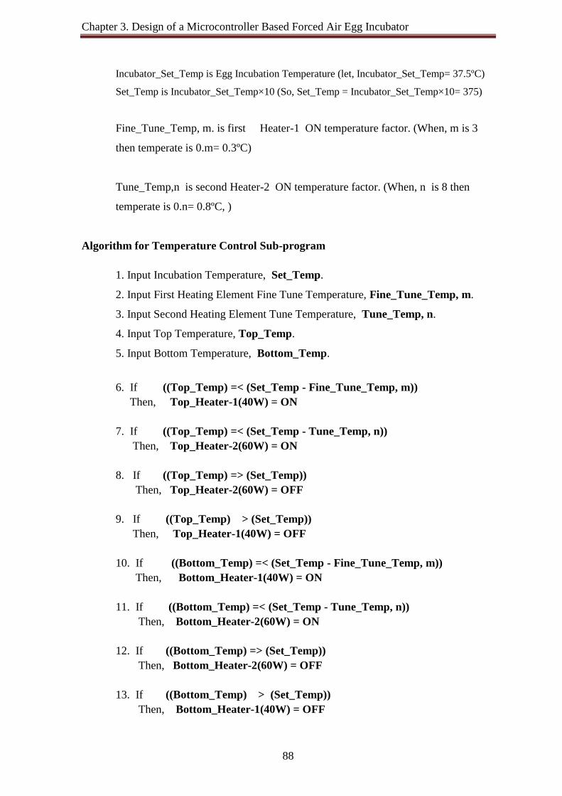
Chapter 3. Design of a Microcontroller Based Forced Air Egg Incubator
88
Incubator_Set_Temp is Egg Incubation Temperature (let, Incubator_Set_Temp= 37.5ºC)
Set_Temp is Incubator_Set_Temp×10 (So, Set_Temp = Incubator_Set_Temp×10= 375)
Fine_Tune_Temp, m. is first Heater-1 ON temperature factor. (When, m is 3
then temperate is 0.m= 0.3ºC)
Tune_Temp,n is second Heater-2 ON temperature factor. (When, n is 8 then
temperate is 0.n= 0.8ºC, )
Algorithm for Temperature Control Sub-program
1. Input Incubation Temperature, Set_Temp.
2. Input First Heating Element Fine Tune Temperature, Fine_Tune_Temp, m.
3. Input Second Heating Element Tune Temperature, Tune_Temp, n.
4. Input Top Temperature, Top_Temp.
5. Input Bottom Temperature, Bottom_Temp.
6. If ((Top_Temp) =< (Set_Temp - Fine_Tune_Temp, m)) Then, Top_Heater-1(40W) = ON 7. If ((Top_Temp) =< (Set_Temp - Tune_Temp, n)) Then, Top_Heater-2(60W) = ON 8. If ((Top_Temp) => (Set_Temp)) Then, Top_Heater-2(60W) = OFF 9. If ((Top_Temp) > (Set_Temp)) Then, Top_Heater-1(40W) = OFF 10. If ((Bottom_Temp) =< (Set_Temp - Fine_Tune_Temp, m)) Then, Bottom_Heater-1(40W) = ON 11. If ((Bottom_Temp) =< (Set_Temp - Tune_Temp, n)) Then, Bottom_Heater-2(60W) = ON 12. If ((Bottom_Temp) => (Set_Temp)) Then, Bottom_Heater-2(60W) = OFF 13. If ((Bottom_Temp) > (Set_Temp)) Then, Bottom_Heater-1(40W) = OFF
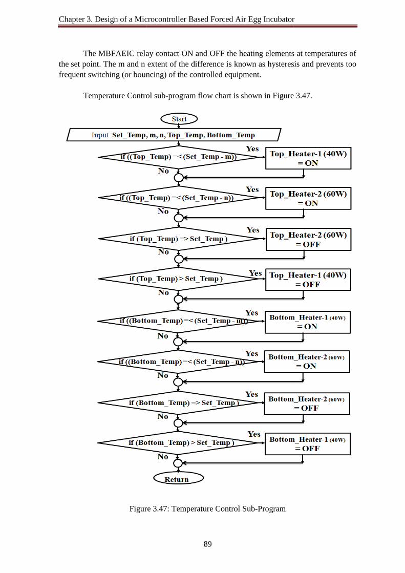
Chapter 3. Design of a Microcontroller Based Forced Air Egg Incubator
The MBFAEIC relay contact ON and OFF the heating elements at temperatures of the set point. The m and n frequent switching (or bouncing) of the controlled equipme
Temperature Control sub
Figure
Microcontroller Based Forced Air Egg Incubator
89
The MBFAEIC relay contact ON and OFF the heating elements at temperatures of m and n extent of the difference is known as hysteresis and prevents too
frequent switching (or bouncing) of the controlled equipment.
Temperature Control sub-program flow chart is shown in Figure
Figure 3.47: Temperature Control Sub-Program
Microcontroller Based Forced Air Egg Incubator
The MBFAEIC relay contact ON and OFF the heating elements at temperatures of extent of the difference is known as hysteresis and prevents too
Figure 3.47.

Chapter 3. Design of a Microcontroller Based Forced Air Egg Incubator
90
3.4.2.7 Humidity Control Sub-Program
The humidity control sub-program flowchart is Figure 3.48:
Figure 3.48: Humidity Control Sub-program 3.4.2.8 Egg Turning Control Sub-Program
This sub-program is used to control the egg tray turning motor based on predefine
turning schedule and real time clock.
3.4.2.9 Ventilation Control and Alarm System Sub-Program
Ventilation Control and Alarm System Sub-Program is used to control ventilation
window and ventilation fan are installed to control proper environmental inside the
incubator. Alarm system help the farmer to is used to take necessary action during
unavailable circumstance. It will give long beep when temperature and humidity is higher

Chapter 3. Design of a Microcontroller Based Forced Air Egg Incubator
91
than required level and short beep when temperature and humidity is lower than required
level.
3.4.2.10 IR Remote Control Transmitter
The PIC16F628A microcontroller is used for IR remote control transmitter. The
built-in oscillator is usually set to operate at 4 MHz and is selected during the
programming of the device. A factory-calibrated oscillator constant is loaded into the last
location of the memory. SIRC protocol based modified IR Transmitter with egg incubator
proposed device code-4 is designed for this incubator.
3.4.2.11 IR Remote Control Receiver
SIRC protocol based IR receiver is designed for and used for operating the egg
turning mechanism.
3.4.2.12 Program Coding
In the design and development of microcontroller based forced air egg incubator
controller, PicBasic Pro Software has been used, it is a Basic compiler for PICs from
microEngineering Labs and MicroCode Studio Plus an IDE from another vendor that
provides a Windows interface, a program editor, an in-circuit debugger, and boot loading
software. The control program for the microcontroller was written in Basic language for
code economy and speed reasons. The overall process includes writing, compiling,
assembling, running, and testing the program. PBP installation typically includes
PICBASIC PRO Compiler, Mecanique's MicroCode Studio IDE, Microchip's MPLAB
IDE, and Microchip's MPASM assembler [56-60].
3.4.2.13 Chips Programming
The PicBasic Pro™ compiler converts the user written BASIC code to assembly
code. It then launches MPLAB assembler which converts the assembly code to a hex file.
Top 2005 programmer is used in chips programming step, when the program is written to
the PIC chip the hex code is converted to binary machine code, which is the only code that
the CPU can understand.

Chapter 3. Design of a Microcontroller Based Forced Air Egg Incubator
92
3.5 PCB Design, Fabrication and Electrical Wiring
The PCBs are designed by using Proteus ISIS to Netlist transfer to ARES. Printed
PCB is etching using toner transfer process then fabricates component and PCBs to a
suitable box.
3.5.1 MBFAEIC Motherboard
The Microcontroller Based Forced Air Egg Incubator Controller (MBFAEIC)
Motherboard build-in with the microcontroller unit and the real time clock-calendar, also it
have interfacing facility of others units like HMI unit, the auto saving data log unit, the
driver unit and the power supply unit. The MBFAEIC motherboard Bottom Copper view,
Top view and 3D visualization shown in Figure 3.49, Figure 3.50 and Figure 3.51.
Figure 3.49: MBFAEIC Motherboard (Bottom Copper View)
Figure 3.50: MBFAEIC Motherboard (Top View)

Chapter 3. Design of a Microcontroller Based Forced Air Egg Incubator
93
Figure 3.51: MBFAEIC Motherboard (3D Visualization using ARES Professional) 3.5.2 PC Interface Card
The PC Interface Card (Top view, Bottom Copper view and 3D visualization)
shown in Figure 3.52.
Figure 3.52: PC Interface Card (Top View, Bottom Copper View and 3D Visualization)

Chapter 3. Design of a Microcontroller Based Forced Air Egg Incubator
94
3.5.3 Relay Driver Card
The four in one Relay Driver Card (Top view and Bottom Copper view and 3D
visualization) shown in Figure 3.53 and Figure 3.54.
Figure 3.53: Relay Driver Card (Top view and Bottom Copper view)
Figure 3.54: Relay Driver Card (3D Visualization)
The single Relay Driver Card with opto-isolator (Top view, Bottom Copper view
and 3D visualization) shown in Figure 3.55.
Figure 3.55: Relay Driver Card with Opto-isolator (Top View, Bottom Copper View and 3D Visualization)

Chapter 3. Design of a Microcontroller Based Forced Air Egg Incubator
95
3.5.4 Fabrication MBFAEI Controller Unit
The PCB cards are assembled in the housing shown in Figure 3.56.
Figure 3.56: MBFAEIC Housing of the PCB Cards The incubator (MBFAEI) Controller in Operation (with Data logging) shown in Figure 3.57.
Figure 3.57: MBFAEI Controller in Operation (Data Logging)

Chapter 3. Design of a Microcontroller Based Forced Air Egg Incubator
96
3.5.5 Electrical Wiring
The Electrical Wiring of Egg turning motor, ventilation and humidity control
System shown in Figure 3.58.
Figure 3.58: Electrical Wiring of Egg turning motor, ventilation and humidity control System
GN
D
+12V
12V
12V
12V
Relay Contact(Control via MBFAEIC)
+88.8kRPM
EGG TRAY TURNINGDC GEAR MOTOR
HUMIDITY CONTROL
+88.8kRPM
VENTILATION FAN
+88.8kRPM
IR R
emote C
ontrol
Manual Sw
itch

Chapter 3. Design of a Microcontroller Based Forced Air Egg Incubator
97
The Electrical Wiring of four heating elements shown in Figure 3.59.
Figure 3.59: Electrical Wiring of Four Heating Elements
BOTTOM HEATER 1
BOTTOM HEATER 2
TOP HEATER 1
TOP HEATER 2
Nut
ral (
N)
Line
(230
V)
40W,230V
60W,230V
40W,230V
Relay Contact(Control via MBFAEIC)
Relay Contact ( Optional Temperature Security System)
60W,230V

Chapter 4 Test Hatching and Performance Analysis 4.1 Introduction
The pre-programmed microcontrollers were placed in the controller PCB. All
temperature and humidity sensors were also placed in their appropriate place in the
incubator and connect the controller. The heating elements, forced air fans, humidification
system, ventilation fan and egg turning system are installed and wiring from the controller.
Incubator Operation
Step 1: When Power of the Incubator is ON. Following welcome screen will appear:
Step 2: The Incubator will initialize itself and restore all previous Set values from
EEPROM and goes for normal operation and Run Mode.
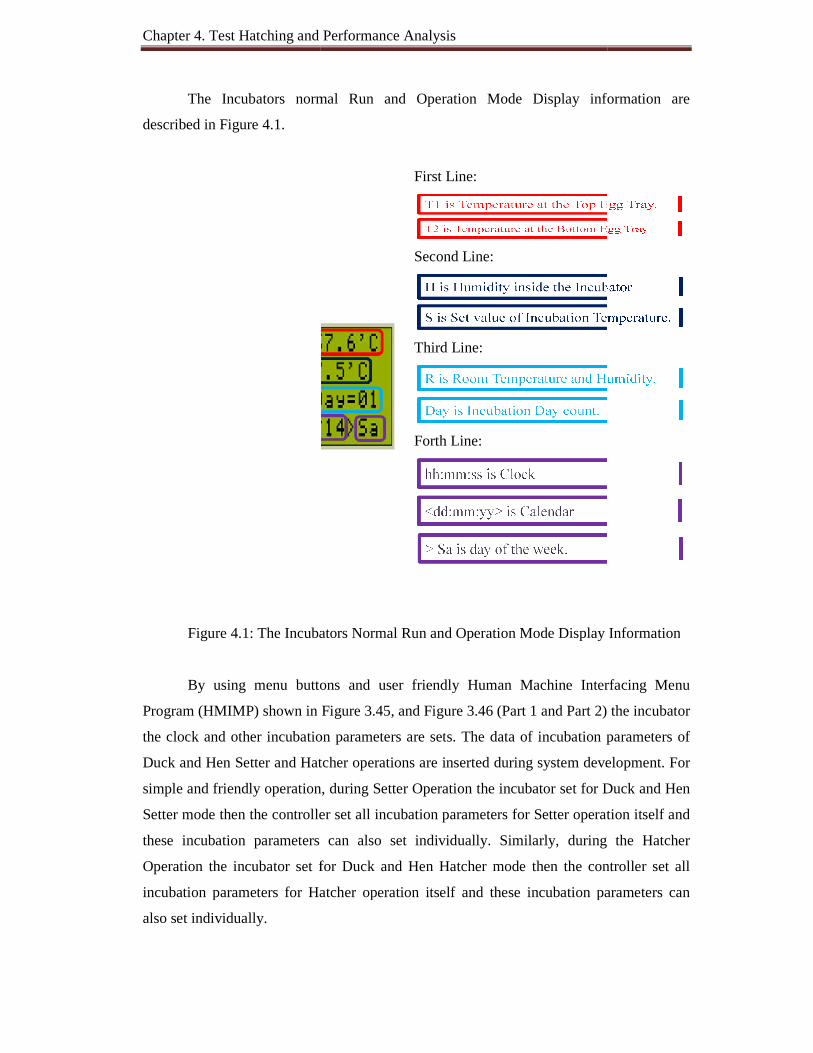
Chapter 4. Test Hatching and Performance Analysis
The Incubators normal Run and Operation Mode Display information are
described in Figure 4.1.
Figure 4.1: The Incubators Normal Run and Operation Mode Display Information
By using menu buttons and user friendly Human Machine Interfacing Menu
Program (HMIMP) shown in Figure 3.45, and Figure 3.46 (Part 1 and Part 2) t
the clock and other incubation parameters are sets.
Duck and Hen Setter and Hatcher operations are inserted during system development.
simple and friendly operation,
Setter mode then the controller set all incubation parameters for Setter operation itself and
these incubation parameters can also set individually. Similarly,
Operation the incubator set for Duck and H
incubation parameters for Hatcher operation itself and these incubation parameters can
also set individually.
Chapter 4. Test Hatching and Performance Analysis
The Incubators normal Run and Operation Mode Display information are
First Line:
Second Line:
Third Line:
Forth Line:
: The Incubators Normal Run and Operation Mode Display Information
buttons and user friendly Human Machine Interfacing Menu
Program (HMIMP) shown in Figure 3.45, and Figure 3.46 (Part 1 and Part 2) t
incubation parameters are sets. The data of incubation parameters of
d Hatcher operations are inserted during system development.
friendly operation, during Setter Operation the incubator set for Duck and Hen
Setter mode then the controller set all incubation parameters for Setter operation itself and
these incubation parameters can also set individually. Similarly, during the
the incubator set for Duck and Hen Hatcher mode then the controller set all
incubation parameters for Hatcher operation itself and these incubation parameters can
The Incubators normal Run and Operation Mode Display information are
: The Incubators Normal Run and Operation Mode Display Information
buttons and user friendly Human Machine Interfacing Menu
Program (HMIMP) shown in Figure 3.45, and Figure 3.46 (Part 1 and Part 2) the incubator
The data of incubation parameters of
d Hatcher operations are inserted during system development. For
the incubator set for Duck and Hen
Setter mode then the controller set all incubation parameters for Setter operation itself and
during the Hatcher
controller set all
incubation parameters for Hatcher operation itself and these incubation parameters can
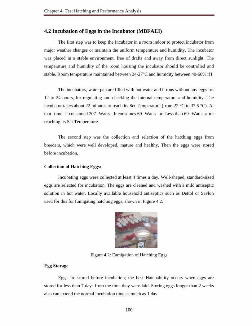
Chapter 4. Test Hatching and Performance Analysis
100
4.2 Incubation of Eggs in the Incubator (MBFAEI)
The first step was to keep the Incubator in a room indoor to protect incubator from
major weather changes or maintain the uniform temperature and humidity. The incubator
was placed in a stable environment, free of drafts and away from direct sunlight. The
temperature and humidity of the room housing the incubator should be controlled and
stable. Room temperature maintained between 24-27°C and humidity between 40-60% rH.
The incubators, water pan are filled with hot water and it runs without any eggs for
12 to 24 hours, for regulating and checking the internal temperature and humidity. The
incubator takes about 22 minutes to reach its Set Temperature (from 22 °C to 37.5 °C). At
that time it consumed 207 Watts. It consumes 69 Watts or Less than 69 Watts after
reaching its Set Temperature.
The second step was the collection and selection of the hatching eggs from
breeders, which were well developed, mature and healthy. Then the eggs were stored
before incubation.
Collection of Hatching Eggs:
Incubating eggs were collected at least 4 times a day. Well-shaped, standard-sized
eggs are selected for incubation. The eggs are cleaned and washed with a mild antiseptic
solution in hot water. Locally available household antiseptics such as Dettol or Savlon
used for this for fumigating hatching eggs, shown in Figure 4.2.
Figure 4.2: Fumigation of Hatching Eggs Egg Storage
Eggs are stored before incubation; the best Hatchability occurs when eggs are
stored for less than 7 days from the time they were laid. Storing eggs longer than 2 weeks
also can extend the normal incubation time as much as 1 day.
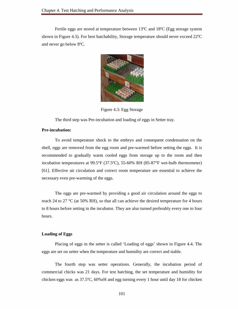
Chapter 4. Test Hatching and Performance Analysis
101
Fertile eggs are stored at temperature between 13ºC and 18ºC (Egg storage system
shown in Figure 4.3). For best hatchability, Storage temperature should never exceed 22ºC
and never go below 8ºC.
Figure 4.3: Egg Storage
The third step was Pre-incubation and loading of eggs in Setter tray. Pre-incubation:
To avoid temperature shock to the embryo and consequent condensation on the
shell, eggs are removed from the egg room and pre-warmed before setting the eggs. It is
recommended to gradually warm cooled eggs from storage up to the room and then
incubation temperatures at 99.5°F (37.5ºC), 55-60% RH (85-87°F wet-bulb thermometer)
[61]. Effective air circulation and correct room temperature are essential to achieve the
necessary even pre-warming of the eggs.
The eggs are pre-warmed by providing a good air circulation around the eggs to
reach 24 to 27 °C (at 50% RH), so that all can achieve the desired temperature for 4 hours
to 8 hours before setting in the incubator. They are also turned preferably every one to four
hours.
Loading of Eggs
Placing of eggs in the setter is called ‘Loading of eggs’ shown in Figure 4.4. The
eggs are set on setter when the temperature and humidity are correct and stable.
The fourth step was setter operations. Generally, the incubation period of
commercial chicks was 21 days. For test hatching, the set temperature and humidity for
chicken eggs was as 37.5ºC, 60%rH and egg turning every 1 hour until day 18 for chicken
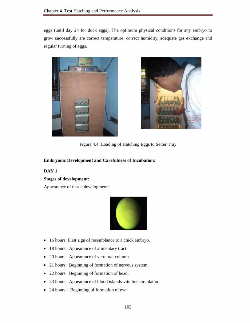
Chapter 4. Test Hatching and Performance Analysis
102
eggs (until day 24 for duck eggs). The optimum physical conditions for any embryo to
grow successfully are correct temperature, correct humidity, adequate gas exchange and
regular turning of eggs.
Figure 4.4: Loading of Hatching Eggs to Setter Tray
Embryonic Development and Carefulness of Incubation: DAY 1
Stages of development:
Appearance of tissue development:
16 hours: First sign of resemblance to a chick embryo.
18 hours: Appearance of alimentary tract.
20 hours: Appearance of vertebral column.
21 hours: Beginning of formation of nervous system.
22 hours: Beginning of formation of head.
23 hours: Appearance of blood islands-vitelline circulation.
24 hours : Beginning of formation of eye.

Chapter 4. Test Hatching and Performance Analysis
103
Precaution / Remarks:
Allow the temperature in the incubator to rise to 36.5° C to 37.5° C.
Maintain the humidity in the incubation box at 55-65% rH.
DAY 2
Stages of development:
• Tissue development very visible
• Appearance of blood vessels
25 hours: Beginning of formation of heart.
35 hours: Beginning of formation of ear.
DAY 3
Stages of development:
Heart beats
Blood vessels very visible
50 hours: Beginning of formation of amnion.
60 hours: Beginning of formation of nasal structure.
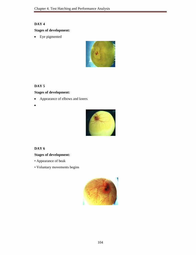
Chapter 4. Test Hatching and Performance Analysis
104
DAY 4
Stages of development:
Eye pigmented
DAY 5
Stages of development:
Appearance of elbows and knees
DAY 6
Stages of development:
• Appearance of beak
• Voluntary movements begins
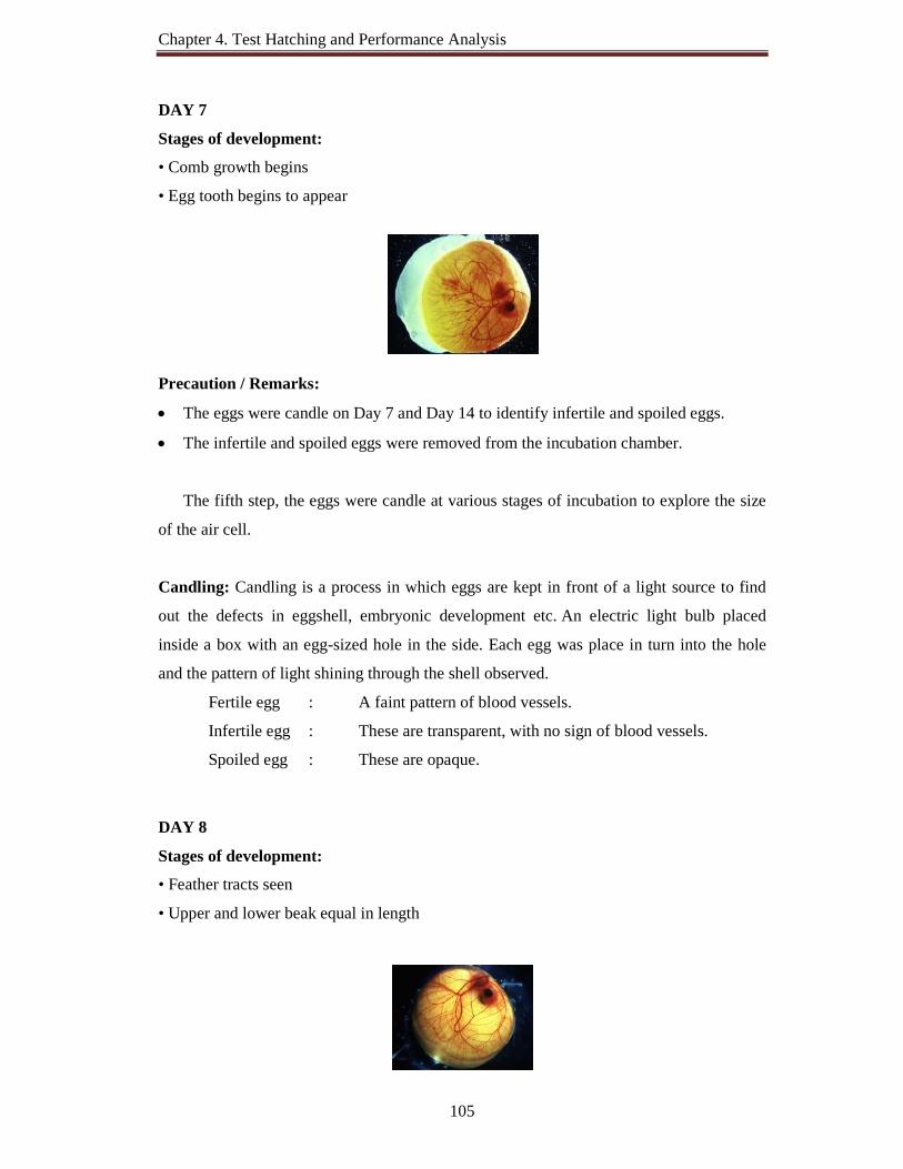
Chapter 4. Test Hatching and Performance Analysis
105
DAY 7
Stages of development:
• Comb growth begins
• Egg tooth begins to appear
Precaution / Remarks:
The eggs were candle on Day 7 and Day 14 to identify infertile and spoiled eggs.
The infertile and spoiled eggs were removed from the incubation chamber.
The fifth step, the eggs were candle at various stages of incubation to explore the size
of the air cell.
Candling: Candling is a process in which eggs are kept in front of a light source to find
out the defects in eggshell, embryonic development etc. An electric light bulb placed
inside a box with an egg-sized hole in the side. Each egg was place in turn into the hole
and the pattern of light shining through the shell observed.
Fertile egg : A faint pattern of blood vessels.
Infertile egg : These are transparent, with no sign of blood vessels.
Spoiled egg : These are opaque.
DAY 8
Stages of development:
• Feather tracts seen
• Upper and lower beak equal in length

Chapter 4. Test Hatching and Performance Analysis
106
DAY 9
Stages of development:
• Embryo starts to look bird-like
• Mouth opening appears
DAY 10
Stages of development:
• Egg tooth prominent
• Toe nails
DAY 11
Stages of development:
• Comb serrated
• Tail feathers apparent
DAY 12
Stages of development:
• Appearance of elbows and knees

Chapter 4. Test Hatching and Performance Analysis
107
DAY 13
Stages of development:
• Appearance of scales
• Body covered lightly with feathers
DAY 14
Stages of development:
• Embryo turns head toward large end of egg
The sixth step, the eggs were again candle on Day 14 to identify infertile and
spoiled eggs. After 14 days, spoiled eggs need to be discarded.
DAY 15
Stages of development:
• Gut is drawn into abdominal cavity.
DAY 16
Stages of development:
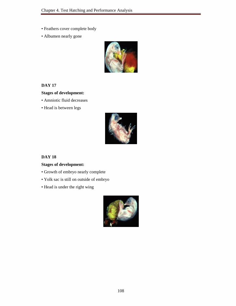
Chapter 4. Test Hatching and Performance Analysis
108
• Feathers cover complete body
• Albumen nearly gone
DAY 17
Stages of development:
• Amniotic fluid decreases
• Head is between legs
DAY 18
Stages of development:
• Growth of embryo nearly complete
• Yolk sac is still on outside of embryo
• Head is under the right wing
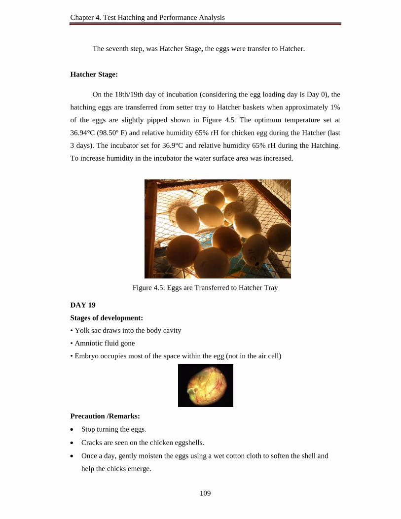
Chapter 4. Test Hatching and Performance Analysis
109
The seventh step, was Hatcher Stage, the eggs were transfer to Hatcher.
Hatcher Stage:
On the 18th/19th day of incubation (considering the egg loading day is Day 0), the
hatching eggs are transferred from setter tray to Hatcher baskets when approximately 1%
of the eggs are slightly pipped shown in Figure 4.5. The optimum temperature set at
36.94°C (98.50º F) and relative humidity 65% rH for chicken egg during the Hatcher (last
3 days). The incubator set for 36.9°C and relative humidity 65% rH during the Hatching.
To increase humidity in the incubator the water surface area was increased.
Figure 4.5: Eggs are Transferred to Hatcher Tray DAY 19
Stages of development:
• Yolk sac draws into the body cavity
• Amniotic fluid gone
• Embryo occupies most of the space within the egg (not in the air cell)
Precaution /Remarks:
Stop turning the eggs.
Cracks are seen on the chicken eggshells.
Once a day, gently moisten the eggs using a wet cotton cloth to soften the shell and
help the chicks emerge.

Chapter 4. Test Hatching and Performance Analysis
110
DAY 20 and DAY 21
Stages of development:
• Yolk sac drawn completely into body
• Embryo becomes a chick (breathing in air in cell)
• Internal and external pip Precaution /Remarks:
Chicks start to come out from the eggs.
Most of the chicks have hatched as shown in Figure 4.6.
Figure 4.6: Successfully Hatched DOCs (Day Old Chicks)
The last step is pulling the hatch, hatchery waste disposal, washing and cleaning
the incubator.
Pulling the Hatch
The process of removing the chicks from the hatcher is often called pulling the
hatch. Chicks are removed from the hatcher as soon as all are hatched and about 95% are
dry. Chicks are held in a room where a temperature of 24°C or more and a relative
humidity of 50% have to be ensured.

Chapter 4. Test Hatching and Performance Analysis
111
Steps involved in Successful Egg Incubation Operations shown in Figure 4.7.
Figure 4.7: Steps Involved in Successful Egg Incubation Operations

Chapter 4. Test Hatching and Performance Analysis
112
4.3 The Incubator (MBFAEI) Hatching Tests and Performance Analysis
Figure 4.8: The Incubator (MBFAEI) Hatched Chicks-1
Figure 4.9: The incubator (MBFAEI) Hatched Ducks

Chapter 4. Test Hatching and Performance Analysis
113
Figure 4.10: The Incubator (MBFAEI) Hatched Chicks-2
Figure 4.11: The Incubator (MBFAEI) Hatched (Multistage) Coturnix Quail

Chapter 4. Test Hatching and Performance Analysis
114
Figure 4.12: The Incubator (MBFAEI) Hatched (Multistage) Chicks
Figure 4.13: Coturnix Quail and Indigenous Chicks Intensive Rearing

Chapter 4. Test Hatching and Performance Analysis
115
The Incubator (MBFAEI) hatching tests were carried out step by step five times.
Depending on the test results the incubator was modified several times and advanced
features are added. The implemented incubator was tested for Hen, Quail and Duck eggs
for single and multistage egg incubation (different types of eggs, of different embryonic
ages).
Figure 4.14: Implemented Incubators
The incubator takes about 22 minutes to reach its Set Temperature (from 22°C to
37.5°C). At that time it consumes 207 Watts. It consumes 69 Watts or less after reaching
its Set Temperature. It consumes approximately 35 kWh (kilowatt-hour) electric powers
for chick (21 days) incubation.
The designed and implemented egg incubators during this project work are shown
in Figure 4.14. The Incubators were developed to serve a dual purpose (i.e. the
combination of Setter and Hatcher in a single unit), unlike the imported type which has a
separate Hatcher and Setter. This Incubator can therefore be adopted by small scale
poultry farmers. The Incubator may use for egg embryo research and laboratory works.
The advanced data logging facility will help to get a right prediction from output data.

Chapter 5 Conclusion and Recommendation 5.1 Conclusion
In this project, microcontroller based forced air egg incubator is designed,
implemented and tested. This project uses microcontroller to control the parameters of
incubator for stable and accurate egg incubation process. The control unit is based on a
PIC microcontroller. It is built for monitoring (room temperature), control (incubator
temperature, egg turning, ventilation and humidity) and displaying different parameters
i.e. temperature, humidity, time, date, set temperature and incubation day etc. User-
friendly Human Machine Interfacing Menu Program (HMIMP) is implemented which
allows the user to visualize different parameters during setting system configuration. The
advanced auto saving data log in excel is very useful and realistic for getting right
prediction from output result to improve incubator operation for optimum performance.
The implemented incubator is tested for Duck, hen and Quail eggs.
On first test Hatching, many clear eggs show no development due to infertile eggs,
One blood ring and dead embryo at an early stage found and late death (17th day)
occurred due egg turning system breakdown problem.
On second test Hatching, the incubator successfully hatches chicken eggs, the
infertile clear egg problem reduced by using selected eggs and Hatching start on 21th
days, only two paralyzed chicks and one piped eggs without hatching problem occurred
due to improper temperature and humidity during load shedding.

Chapter 5. Conclusion and Recommendation
117
Depending on second test hatching the incubator is modified for third Hatching,
the incubator successfully hatches duck eggs, hatching start on 2127 days. During hatching
eggs are collected from local farmer most of eggs laid in dirty place and covered by
contaminating microorganisms from the feces or feather material of the parents, some eggs
are unhatched because of infection caused by a bacterium that enters through the porous
egg shell and kills some embryo’s and newly hatched chicks but other ducks are still alive
and going on full egg production.
For Fourth test hatching, the incubator casing was reconstructed and the insulation
layers are increased to reduce the heat loss, IPS was connected for continuous power
supply. Eggs are collected from own parent breeders. In this test hatching, all chicken eggs
are successfully hatched in good condition; the chicks were healthy and standard size.
Hatching started on the 20th day, and most of the chicks hatch within 4-5 hours, 100%
hatchability found during this hatching.
Multistage incubation tested on Fifth test hatching containing different eggs (Quail,
Hen and Duck) of different embryonic ages. Hen and Quail eggs are collected from own
parent breeders and duck eggs were collected from local farmers. Quail hatching starts on
the 16th day, and the entire Quail baby hatched within 2-3 hours. 100% hatchability found
during multistage Quail hatching. Chick hatching started on 20th day and the entire chick
hatched within 4-5 hours. 100% hatchability found during multistage chick hatching. Duck
hatching started on 27th day and some eggs were successfully hatched but some eggs were
unhatched because of infertility and infection. The Quail and Chicks are put in same
brooder and due to intensive rearing they are in good condition; due to lack of sufficient
brooder and proper knowledge of duck rearing, baby ducks cannot rearing properly.
During test hatching it is found that when continuous power supply used then
incubation period slightly decrease, chicks were healthy and good size and 100%
hatchability found, also when eggs are collected from own parent breeders than there is no
infection and infertility problems.
Chapter 5. Conclusion and Recommendation
118
5.2 Recommendations
This designed incubator model could be one of the cheapest with a manageable
capacity of eggs, beneficial to small scale to large scale poultry farmers and research
laboratory. The incubator can be modified to run on solar or wind power since the power
requirement of the incubator after reaching its set temperature is quite low (69 Watts or
less than 69 Watts), which may be helpful for the rural breeders, where there is a frequent
power cut or no electrical power supply. In future, this project can be modified by using a
PID controller with overshoot as low as possible using higher-end microcontroller to
control temperature also improve the turning system.

References
[1] M. M. H. Mandol, P. M. Das, M. A. Haqu, M. K. Islam, “Common Diseases of Smallholder Poultry and Their Control in Bangladesh,” The Bangladesh Model and Other Experiences in Family Poultry Development, 2002.
[2] “Statistical Pocket Book of Bangladesh,” Bangladesh Bureau of Statistics, Statistics Division, Ministry of Planning, Government of the People’s Republic of Bangladesh, Dhaka, 2008, 2010.
[3] S. Akhter, “Broiler Farming under Aftab Bahamuhkhi Farm Limited Supervision and Farmers Own Management: a Comparative Efficiency Analysis,” M. S. Thesis, Department of Agricultural Economics, Bangladesh Agricultural University, Mymensingh, 2008.
[4] N. Akter, “An Economic Analysis of Layer Farming in Some Selected Areas of Taingail District,” M. S. Thesis, Department of Agricultural Economics, Bangladesh Agricultural University, Mymensingh, 2008.
[5] M. S. Islam, “Comparative Performance of Sonali and Fayoumi Chickens from Day Old to Eight Weeks of Age with or without Supplementary Feeding,” M.S. Thesis, Department of Poultry Science, Bangladesh Agricultural University, Mymensingh, 2005.
[6] S. D. Chowduary, “Opportunities and Challenges Facing Commercial Poultry Production in Bangladesh,” Eighth International Poultry Show and Seminar, WPSA-BB, Dhaka, Bangladesh, 2013.
[7] “Bangladesh Economic Review,” Economic Advisers Wing, Finance Division, Ministry of Finance, Government of Peoples Republic of Bangladesh, Dhaka, 2011.
[8] T. M. Shafey, H. A. Al-Batshan and M. M. Ghannam, “Effects of electrical field on hatchability performance of eggs from a layer-type breeder,” British poultry science, Vol. 48, No. 2, pp. 145-153, 2007.
[9] J. H. Sutcliffe, INCUBATION Natural and Artificial, Cornell University Library.

References
120
[10] B. C. Roy, H. Ranvig, S. D. Chowdhury, M. M. Rashid and M. R. Faruque, “Production of day-old chicks from crossbred chicken eggs by broody hens, rice husk incubator and electric incubator, and their rearing up to 6 weeks,” Project Report of Livestock Research for Rural Development, Vol. 16, No. 3, 2004. ISSN 0121-3784.
[11] A. Rota and S. R. M. Rahman, Building and operating a mini-hatchery: Sand method, Training Manual, Published by PKSF and IFAD, Rome, Italy.
[12] J. Hassan, “Mini-hatchery: a low cost hatching technology,” BDvat iNewsletter, Vol. 1, Issue 2, April 2011.
[13] M. L. Hamre, “Hatching and Brooding Small Numbers of Chicks,” University of Minnesota Extension, University of Minnesota, 2008.
[14] Reininger, “Artificial incubation of bird eggs: update”, American Association of Zoo Parks and Aquarium Regional Proceedings, pp. 427 – 435, K.1985.
[15] Van Der Heyden, “Artificial incubation,” Bird World Vol. 9, No. 5, pp. 62-65, N 1987.
[16] S. Yalçin and P. B. Siegel, “Exposure to cold or heat during incubation on developmental stability of broiler embryos,” Poultry Science Vol. 82, pp. 1388-1392, 2003.
[17] J. L. Black and W. W. Burggren, “Acclimation to hypothermic incubation in developing chicken embryos (Gallus domesticus) I. Developmental effects and chronic and acute metabolic adjustments,” J. Exp. Biol. Vol. 207, pp. 1543–1552, 2004.
[18] N. A. French, “Modeling incubation temperature: the effect of incubation design,” Embryonic development and egg size poultry, Vol. 76, pp. 124-133, 1997.
[19] Meijerhof, R., Embryo temperature as a tool in the incubation process, Incubation and fertility Research Group [WPSA Working Group 6], Edmund Hall, Oxford, UK, 2000.
[20] AL. Romanoff, “The avian embryo: structural and functional development,” New York, Macmillan, 1960.
[21] C. Deeming, “Relative humidity affects water loss from eggs. Weight loss from bird eggs and relative humidity,” Misset-World Poultry, Vol. 9, No. 5, pp. 33-37, 1993.
[22] H. Lundy, “A review of the effects of temperature, humidity and gaseous exchange environment in the incubator on the hatchability of the hen’s eggs,” Pages 143–176 in The Fertility and Hatchability of the Hen’s Egg. T. C. Carter and B. M. Freeman, ed. Oliver and Boyd, Edinburgh, UK, 1969.

References
121
[23] H. G. Barott, “Effect of temperature, humidity, and other factors on hatch of hen's eggs and on energy metabolism of chick embryo,” USD, A Technical Bulletin N0. 553, Washington, DC, 1937.
[24] B. M. Freeman, “The emergence of the homoeothermic metabolic response in the fowl,” Comp. Biochem. Physiol., Vol. 13, pp. 413-422, 1964.
[25] B. M. Freeman, “The effects of cold, noradrena-line and adrenaline on oxygen consumption and carbo-hydrate metabolism of the young fowl,” Comp. Biochem, Physiol, Vol. 18, pp. 369–382, 1966.
[26] D. R. Wekstein and J. F. Zolman, “Development of the young chick,” Proc. Soc. Exp. Biol. Med., Vol. 125, pp. 294–297, 1967.
[27] D. R. Wekstein and J. F. Zolman , “Cold stress regulation in young chicks,” Poultry Science, Vol. 50, pp. 56–61, 1971.
[28] J. B. Thompson, H. R. Wilson and R. A. Voitle, “Influence of high temperature stress of 16-day embryos on subsequent hatchability,” Poultry Science, Vol. 55, pp. 892-894, 1976.
[29] H. R. Wilson, “Physiological requirements of the developing embryo: temperature and turning,” In: Avian Incubation (Tullett, S.G.,Ed.), Butterworth Heinemann, London, pp. 145-156, 1991.
[30] G. S. Swann, J. Brake, “Effect of dry-bulb temperature, relative humidity, and eggshell conductance during the first three days of incubation on egg weight loss and chick weight,” Poultry Science, Vol. 69, pp. 535-544, 1990b.
[31] A. L. Romanoff, “Effect of composition of air on the growth and mortality of the chick embryo,” J. Morph. Physiol., Vol. 50, pp. 517-525, 1930.
[32] Decuypere, E. Michels, “Incubation temperature as a management tool: a review,” Poultry Science, Vol. 48, pp. 28-38, 1992.
[33] J. S. Jeffrey, G.P. Martin and R.C. Fanguy, “The incubation of ratite eggs,” Texas A & M University System, 2008.
[34] A. Schwartz, J. D. Weaver, N.R. Scott and T.J. Cade, “Measuring the temperature of eggs during incubation under captive Falcons,” Journal of Wildlife Management, Vol. 41, pp. 12-17, 1977.
[35] A. L. Romanoff and H. A. Faber, “Effect of temperature on the growth, fat, and calcium metabolism and mortality of the chick embryo during the latter part of incubation,” J. Cell. Comp. Physiol., Vol. 2, pp. 457–466, 1933.

References
122
[36] Reininger, Artificial incubation of bird eggs. Animal Keepers Forum, Vol. 10, pp. 418-423, 1983.
[37] M. E. Suarez, H. R. Wilson, F. B. Mather, C. J. Wilcox and B N McPherson, “Effects of strain and age of the broiler breeder female on incubation time and chick weight,” Poultry Science, Vol.76, pp. 1029–1036, 1997.
[38] W. M. Insko, Physical conditions in incubation, Pages 210–243 in The Fertility and Hatchability of Chicken and Turkey Eggs. L. W. Taylor, ed. J. Wiley and Sons Inc., London, UK, 1949.
[39] W. Landauer, “Hatchability of chicken eggs as influenced by environment and heredity,” Storrs Agricultural Experiment Station, Connecticut, 1967.
[40] A. L. Romanoff, L. L. Smith and R. A. Sullivan, “Biochemistry and biophysics of the developing hen’s egg & Influence of temperature,” Memorandum of Cornell University Ag. Exp. Sta., Vol. 216, pp. 1-42, 1938.
[41] T. B. Ande and H. R. Wilson, “Hatchability of chicken embryos exposed to acute high temperature stress at various ages,” Poultry Science, Vol. 60, pp. 1531-1566, 1981.
[42] K. Tona, O. Onagbesan, B. De Ketelaere, E. Decuypere, and V. Bruggeman “Effects of turning duration during incubation on corticosterone and thyroid hormone levels, gas pressures in air cell, chick quality and juvenile growth,” Poultry Science, Vol. 82, pp. 1974–1979, 2003.
[43] D. C. Deeming, “Characteristics of unturned eggs: critical period, retarded embryonic growth and poor albumen utilization,” Poultry Science, Vol. 30, pp. 239-249, 1989a.
[44] H. R. Wilson and R. F. Wilmering, “Hatchability as affected by egg turning in high density plastic egg flats during the last half of incubation,” Poultry Science, Vol. 67, pp. 685-688, 1988.
[45] A. H. Lourens, Van den brand, R. Meijerhot and B. Kemp, “Effect of eggshell temperature during incubation on embryo development, hatchability and post hatch development,” Poultry Science, Vol. 84, pp. 914-920, 2005.
[46] M Meir and A Ar, “Increasing hatchability of turkey eggs by matching incubator humidity to shell conductance of individual eggs,” Poultry Science, Vol. 63, pp. 1489-1496, 1984.
[47] F. G. Burton and Tullet, “The effect of egg weight and shell porosity on the growth and water balance of the chicken embryo,” Comparative Biochemistry and Physiology-Part A, Vol. 75, pp. 167-174, S.G.,1985.
References
123
[48] D. M. Bird and Laque, “Fertility, egg weight loss, hatchability, and fledgling success in replacement clutches of captive American Kestrels,” Canadian Journal of Zoology , Vol. 60, pp. 80-88, P. C. 1980.
[49] P. D. Olsen and Olsen, “Egg weight loss during incubation in captive Australian Kestrels Falco cenhroides and Brown Goshawks Accipiter fasciatus,” Emu, Vol. 87, pp. 196-199, 1987.
[50] C. A. Weinheimer and J. R Spotila, “Shell resistance and evaporative water loss from bird eggs: Effects of wind speed and egg size,” American Zoologist, Vol. 18, p. 636, 1978.
[51] PIC16F87X Data Sheet - Microchip, ww1.microchip.com/downloads/en/DeviceDoc / 30292c .pdf
[52] LM35 datasheet, http://www.ti.com/ general/docs/lit/getliterature.tsp? generic PartNumber= lm35 &fileType=pdf
[53] DS18B20 datasheet , http://datasheets.maximintegrated.com/en/ds/DS18B20.pdf
[54] HSM-20G datasheet, http://www.seeedstudio.com/ depot/ datasheet/ HSM-20G.pdf
[55] DS1302 datasheet, http://datasheets. maximintegrated.com /en/ds /DS1302.pdf
[56] www.microchip.com
[57] www.melabs.com
[58] http://PBP3.com.
[59] www.mecanique.co.uk
[60] http://pbp3.com/downloads/PBP_Reference_Manual.pdf
[61] R. Haigh, “The breeding and artificial incubation of hawks, buzzards and falcons Accipiter,” International Zoo Year book, Vol. 23, pp. 51-58, 1984.

Appendix A: Firmware Development for MBFAEI
'******************************************************************************************** '* Name : Design and Implementation of a Microcontroller Based Forced Air Egg Incubator * '* * '* Author : * '* Muhammad Anowar Kabir (MIEB-26234), [email protected] * '* Master of Engineering in Electrical and Electronic Engineering,DUET * '* Supervisor: Prof. Dr. Md. Anwarul Abedin, * '* Head, EEE Department, DUET,Gazipur * '* Notice : Sample Code * * Version : * '* Notes : 01818713364 * '* : * '* Date : 7/20/2014,, * '******************************************************************************************** '''''''''''''''''''''''''''''''''''''''''''''''''''''''''''''''''''''''''''''''' ''''''''''''''''''''''''''''CONFIGERATION''''''''''''''''''''''''''''''''''''''' #CONFIG __CONFIG _CP_OFF & _WDT_ON & _BODEN_ON & _PWRTE_ON & _HS_OSC & _WRT_OFF & _LVP_OFF & _CPD_OFF #ENDCONFIG '''''''''''''''''''''''''''''''''''''''''''''''''''''''''''''''''''''''''''''''' DEFINE OSC 8 '''''''''''''''''''''''''''''CONFIGERATION'''''''''''''''''''''''''''''''''''''' '''''''''''''''''''''''''''''''''''''''''''''''''''''''''''''''''''''''''''''''' '''''''''''''''''''''''''''''''''''''''''''''''''''''''''''''''''''''''''''''''' '''''''''''''''''''''''''''''''''PORT SETUP''''''''''''''''''''''''''''''''''''' TRISA=%111111 TRISB=%00000001 TRISC=%00000000 TRISD=%11100000 TRISE=%00000000 PORTA=0 PORTB=0 PORTC=0 PORTD=0 PORTE=0 '''''''''''''''''''''''''''''''''''''''''''''''''''''''''''''''''''''''''''''''' '''''''''''''''''''''''''''''''''PORT SETUP''''''''''''''''''''''''''''''''''''' 'LCD PORT SETUP DEFINE LCD_DREG PORTB DEFINE LCD_DBIT 4 DEFINE LCD_RSREG PORTB DEFINE LCD_RSBIT 2 DEFINE LCD_EREG PORTB DEFINE LCD_EBIT 3 DEFINE LCD_BITS 4 DEFINE LCD_LINES 4 symbol BUTTOM_HEATER_1 =PORTD.0 symbol BUTTOM_HEATER_2 =PORTD.1 symbol TOP_HEATER_1 =PORTD.2 symbol TOP_HEATER_2 =PORTD.3 SYMBOL BUZER =PORTD.4 MENU_BUTTON VAR PORTD.5 UP_BUTTON VAR PORTD.6 DOWN_BUTTON VAR PORTD.7 SYMBOL EGG_TURNING_MOTOR =PORTC.0 symbol HUMIDIFIER_FAN =PORTC.1 symbol VENTILATION_MOTOR =PORTC.2 RTC_CLK var PORTE.0 RTC_DTA var PORTE.1 RTC_RST var PORTE.2

Appendix A: Firmware Development for MBFAEI
125
m var byte n var byte 'VERIABLE USED FOR RTC SEC VAR BYTE MINITE VAR BYTE HOUR VAR BYTE INCUBATION_DAY VAR BYTE DATE VAR BYTE MONTH var byte YEAR var byte DAY VAR BYTE BOX var byte 'VERIABLE USED FOR RTC NUMBER VAR BYTE ONETH VAR BYTE TENTH VAR BYTE ADCON1 = %10000010 'AE0-AE2 =Digital ,AN0-AN5=Analog Define ADC_BITS 10 Define ADC_CLOCK 3 Define ADC_SAMPLEUS 50 adchsm var word 'word is 16 bit , 65535 hsm var word HUM_abc var word HUM_ab var word HUM_cd var word hum_d_ab var word adclm35_1 var word lm35_1 var word adchsm2 var word hsm2 var word HUMIDITY VAR BYTE HUM VAR BYTE TSET VAR BYTE T_SET VAR BYTE TSET_T VAR word ''''''''''''''''''''''''''''''''''''''''''''''''''''''''''''''''''''''''' SYMBOL DS18_COMM_PIN_DQ_TOP=PORTB.1 DS18_TEMP_IN_CELCIUS VAR WORD Float VAR WORD PLUS_MINUS_SIGN VAR BYTE Busy VAR BIT RAW_TEMP VAR WORD NEGATIVE_TEST_BIT VAR RAW_TEMP.Bit11 NEGATIVE_TEMP CON 1 '''''''''''''''''''''''''''''''''''''''''''''''''''''''''''''''''''''''' SYMBOL DS18_COMM_PIN_DQ_BUTTOM=PORTC.4 DS18_TEMP_IN_CELCIUS1 VAR WORD Float1 VAR WORD Busy1 VAR BIT PLUS_MINUS_SIGN1 VAR BYTE RAW_TEMP1 VAR WORD NEGATIVE_TEST_BIT1 VAR RAW_TEMP1.Bit11 NEGATIVE_TEMP1 CON 1 '''''''''''''''''''''''''''''''''''''''''''''''''''''''''''''''''''''''' SET VAR BYTE AIR VAR BIT MOTOR_C VAR BIT EGG_TURNING_TYPE VAR BYTE SEC_STOP VAR BYTE MENU_NO VAR BYTE

Appendix A: Firmware Development for MBFAEI
126
CREADITE_GOES_TO: LCDOUT $FE,$84,"Ok." 'LCDOUT $FE,$80,"Automatic Incubator" 'lcdout $FE,$C0," M A Kabir" 'LCDOUT $FE,$94," MEng.-102211" 'lcdout $FE,$D4," DR. A ABDIN,DUET" PAUSE 1000 '''''''''''''''''''''''''''''''''''''''''''''''''''''''''''''''''''''''''''''''' START: MENU_NO=0 SET=1 READ $01,TSET:IF TSET=255 THEN TSET=0 READ $02,HUMIDITY:IF HUMIDITY=255 THEN HUMIDITY=0 READ $09,SEC_STOP:IF SEC_STOP=255 THEN SEC_STOP=0 READ $07,INCUBATION_DAY:IF INCUBATION_DAY=255 THEN INCUBATION_DAY=0 READ $10,EGG_TURNING_TYPE:IF EGG_TURNING_TYPE=255 THEN EGG_TURNING_TYPE=0 READ $11,T_SET:IF T_SET=255 THEN T_SET=1 READ $06,MOTOR_C AIR=1 READ $04,m:IF m=255 THEN m=0 READ $05,n:IF n=255 THEN n=0 Pause 2 gosub RTC_SENSOR_READ Pause 2 GOSUB TEMP_SENSOR_DS18_READ Pause 10 GOSUB TEMP_SENSOR_DS18_READ1 Pause 1000 LCDOUT $FE,1 'Clear screen. Pause 10 ''''''''''''''''''''''''''''''''''''''''''''''''''''''''''''''''''''''''''''''' 'MAIN PROGRAM '''''''''''''''''''''''''''''''''''''''''''''''''''''''''''''''''''''''''''''''' MAIN: GOSUB HSM_20G_HUM GOSUB HSM_20G_HUM2 gosub read_LM35_1 Pause 1 GOSUB TEMP_SENSOR_DS18_READ Pause 1 GOSUB TEMP_SENSOR_DS18_READ1 Pause 1 GOSUB RTC_SENSOR_READ Pause 1 GOSUB DAY_OF_WEEK GOSUB DISPLAY GOSUB ROOM_HEATING_CONTROL GOSUB HUMIDITY_CONTROL Pause 3 GOSUB DATA_LOGGER IF MOTOR_C=1 THEN GOSUB EGG_TURNING_MOTOR_CONTROL ENDIF IF MENU_BUTTON=1 THEN GOTO MENU_CHANGE goto MAIN '''''''''''''''''''''''''''''''''''''''''''''''''''''''''''''''''''''''''''''''' 'MAIN PROGRAM ''''''''''''''''''''''''''''''''''''''''''''''''''''''''''''''''''''''''''''''''

Appendix A: Firmware Development for MBFAEI
127
'''''''''''''''''''''''''''''''''''''''''''''''''''''''''''''''''''''''''''''''' 'DS18B20 Temperature sensor read '''''''''''''''''''''''''''''''''''''''''''''''''''''''''''''''''''''''''''''''' TEMP_SENSOR_DS18_READ: OWOUT DS18_COMM_PIN_DQ_TOP, 1, [$CC, $44] WAIT_H: OWIN DS18_COMM_PIN_DQ_TOP, 4, [Busy] ' IF Busy = 0 THEN WAIT_H OWOUT DS18_COMM_PIN_DQ_TOP, 1, [$CC, $BE] OWIN DS18_COMM_PIN_DQ_TOP, 2, [RAW_TEMP.Lowbyte, RAW_TEMP.Highbyte] GOSUB DS18_DATA_TO_CELCIUS_CAL RETURN DS18_DATA_TO_CELCIUS_CAL: PLUS_MINUS_SIGN = "+" IF NEGATIVE_TEST_BIT = NEGATIVE_TEMP THEN PLUS_MINUS_SIGN = "-" RAW_TEMP=~RAW_TEMP+2 endif float = (RAW_TEMP*10)/16 DS18_TEMP_IN_CELCIUS=FLOAT/10 IF MENU_BUTTON=1 THEN GOTO MENU_CHANGE RETURN '''''''''''''''''''''''''''''''''''''''''''''''''''''''''''''''''''''''''''''''' '''''''''''''''''''''''''''''''''''''''''''''''''''''''''''''''''''''''''''''''' ‘’’’’’’’’’’’’’’’’’’’’’’’’’’’’’’’’’’’’’’’’’’’’’’’’’’’’’’’’’’’’’’’’’’’’’’’’’’’’’’ '''''''''''''''''''''''''''''''''''''''''''''''''''''''''''''''''''''''''''''''' 'Temperature Control Sub-program '''''''''''''''''''''''''''''''''''''''''''''''''''''''''''''''''''''''''''''''' ROOM_HEATING_CONTROL: '''''''''''''''''''''''''''''''''''''''''''''''''''''''''''''''''''''''''''''''' TSET_T =TSET*10+T_SET if FLOAT>TSET_T then LOW TOP_HEATER_2 ENDIF '''''''''''''''''''''''''''''''''''''''''''''''''''''''''''''''''''''''''''''''' '''''''''''''''''''''''''''''''''''''''''''''''''''''''''''''''''''''''''''''''' if FLOAT=<TSET_T-m then high TOP_HEATER_1 ENDIF if FLOAT=<TSET_T-n then high TOP_HEATER_2 ENDIF '''''''''''''''''''''''''''''''''''''''''''''''''''''''''''''''''''''''''''''''' '''''''''''''''''''''''''''''''''''''''''''''''''''''''''''''''''''''''''''''''' if float1>TSET_T then LOW BUTTOM_HEATER_1 LOW BUTTOM_HEATER_2 ENDIF '''''''''''''''''''''''''''''''''''''''''''''''''''''''''''''''''''''''''''''''' '''''''''''''''''''''''''''''''''''''''''''''''''''''''''''''''''''''''''''''''' if float1=<TSET_T-m then high BUTTOM_HEATER_1 ENDIF if float1=<TSET_T-n then high BUTTOM_HEATER_2 ENDIF '''''''''''''''''''''''''''''''''''''''''''''''''''''''''''''''''''''''''''''''' '''''''''''''''''''''''''''''''''''''''''''''''''''''''''''''''''''''''''''''''' if FLOAT=>TSET_T+2 OR float1=>TSET_T+2 OR HUMIDITY+5<hum_d_ab then HIGH VENTILATION_MOTOR GOSUB BIPBIP ELSE LOW VENTILATION_MOTOR '

Appendix A: Firmware Development for MBFAEI
128
ENDIF '''''''''''''''''''''''''''''''''''''''''''''''''''''''''''''''''''''''''''''''' '''''''''''''''''''''''''''''''''''''''''''''''''''''''''''''''''''''''''''''''' if FLOAT<TSET_T-30 OR float1<TSET_T-30 OR HUMIDITY-5>hum_d_ab then GOSUB BIP ENDIF '''''''''''''''''''''''''''''''''''''''''''''''''''''''''''''''''''''''''''''''' IF MENU_BUTTON=1 THEN GOTO MENU_CHANGE RETURN '''''''''''''''''''''''''''''''''''''''''''''''''''''''''''''''''''''''''''''''' '''''''''''''''''''''''''''''''''''''''''''''''''''''''''''''''''''''''''''''''' '''''''''''''''''''''''''''''''''''''''''''''''''''''''''''''''''''''''''''''''' '''''''''''''''''''''''''''''''''''''''''''''''''''''''''''''''''''''''''''''''' 'Display '''''''''''''''''''''''''''''''''''''''''''''''''''''''''''''''''''''''''''''''' DISPLAY: lcdout $FE,$80,"T1=",DEC DS18_TEMP_IN_CELCIUS1,".",DEC1 (FLOAT1),"'C, T2=",DEC DS18_TEMP_IN_CELCIUS,".",DEC1 (FLOAT),"'C" lcdout $FE,$C0,"H=",DEC hum_d_ab,"%rH, Set=",DEC2 TSET,".",DEC1 T_SET,"'C" LCDOUT $FE,$94,"R=",DEC lm35_1/100,".",DEC1 lm35_1,"C,",DEC hsm2,"%rH",",Day=",DEC2 INCUBATION_DAY LCDOUT $FE,$D4,DEC2 HOUR,":",DEC2 MINITE,":",DEC2 SEC,"<",DEC2 DATE,"/",DEC2 MONTH,"/",DEC2 YEAR IF SEC=>SEC_STOP THEN LOW EGG_TURNING_MOTOR IF HOUR=6 AND MINITE=6 AND SEC=6 THEN INCUBATION_DAY=INCUBATION_DAY+1 IF INCUBATION_DAY=31 THEN INCUBATION_DAY=0 WRITE $07,INCUBATION_DAY ENDIF IF SEC>60 THEN GOSUB bip SEC=0 GOSUB TIMESET Pause 4 SEC=0 GOSUB TIMESET GOTO START ENDIF RETURN '''''''''''''''''''''''''''''''''''''''''''''''''''''''''''''''''''''''''''''''' '''''''''''''''''''''''''''''''''''''''''''''''''''''''''''''''''''''''''''''''' '''''''''''''''''''''''''''''''''''''''''''''''''''''''''''''''''''''''''''''''' 'DS1302 Real Time Clock(RTC) Read '''''''''''''''''''''''''''''''''''''''''''''''''''''''''''''''''''''''''''''''' RTC_SENSOR_READ: high RTC_RST OUTPUT RTC_DTA shiftout RTC_DTA, RTC_CLK, 0, [$BF] INPUT RTC_DTA SHIFTIN RTC_DTA, RTC_CLK, 1, [SEC, MINITE, HOUR,DATE , MONTH, DAY, YEAR, BOX] BOX=SEC :GOSUB BCDTODEC :SEC=NUMBER BOX=MINITE :GOSUB BCDTODEC :MINITE=NUMBER BOX=HOUR :GOSUB BCDTODEC :HOUR=NUMBER BOX=DATE :GOSUB BCDTODEC :DATE=NUMBER BOX=MONTH :GOSUB BCDTODEC :MONTH=NUMBER BOX=YEAR :GOSUB BCDTODEC :YEAR=NUMBER BOX=DAY :GOSUB BCDTODEC :DAY=NUMBER low RTC_RST return BCDTODEC: ONETH=BOX & %01110000 ONETH=ONETH>>4 TENTH=BOX & %00001111 NUMBER=ONETH*10+TENTH return DAY_OF_WEEK: SELECT CASE DAY

Appendix A: Firmware Development for MBFAEI
129
CASE 1 LCDOUT $FE,$E5,">Su" CASE 2 LCDOUT $FE,$E5,">Mo" CASE 3 LCDOUT $FE,$E5,">Tu" CASE 4 LCDOUT $FE,$E5,">We" CASE 5 LCDOUT $FE,$E5,">Th" CASE 6 LCDOUT $FE,$E5,">Fr" CASE 7 LCDOUT $FE,$E5,">Sa" END SELECT RETURN ''''''''''''''''''''''''''''''''''''''''''''''''''''''''''''''''''''''''''''''' MENU_NAMEs: SELECT CASE MENU_NO CASE 0 lcdout $fe,$80,"Pres MENU/UP/Dn" 'LCDOUT $FE,$C0," " 'lcdout $fe,$80,"MENU PROGM.IN/OUT" 'lcdout $fe,$c0,"Press BUTTON " 'LCDOUT $FE,$94,"MENU >to Set " 'LCDOUT $FE,$D4,"UP/DOWN>next Menu" 'LCDOUT $FE,$D4,"Press MENU/UP/Down" IF MENU_BUTTON=1 THEN END_MENU_SET CASE 1 ' ' lcdout $fe,$80,"Hen & Duck Eggs" LCDOUT $FE,$c0," Setter mode" IF MENU_BUTTON=1 then GOSUB BIP TSET =37:T_SET=5:m=2:n=5:HUMIDITY= 60:MOTOR_C=1:SEC_STOP=1:EGG_TURNING_TYPE=1 'SEC_STOP=1 Depends on Gear System WRITE $01,TSET:PAUSE 2 WRITE $11,T_SET:PAUSE 2 WRITE $02,HUMIDITY:PAUSE 2 WRITE $06,MOTOR_C:PAUSE 2 WRITE $10,EGG_TURNING_TYPE :PAUSE 2 WRITE $09,SEC_STOP:PAUSE 2 WRITE $04,m:PAUSE 2 WRITE $05,n:PAUSE 2 WHILE MENU_BUTTON=1:WEND GOTO MENU_CHANGE ENDIF CASE 2 ' lcdout $fe,$80,"Hen & Duck Eggs" LCDOUT $FE,$c0," Hatcher mode" IF MENU_BUTTON=1 then GOSUB BIP TSET =36:T_SET=8:HUMIDITY= 70:MOTOR_C=0:SEC_STOP=0:EGG_TURNING_TYPE=0:m=2:n=5 WRITE $01,TSET:PAUSE 2 WRITE $11,T_SET:PAUSE 2 WRITE $02,HUMIDITY:PAUSE 2 WRITE $06,MOTOR_C:PAUSE 2 WRITE $09,SEC_STOP:PAUSE 2 WRITE $10,EGG_TURNING_TYPE :PAUSE 2 WRITE $04,m:PAUSE 2 WRITE $05,n:PAUSE 2 WHILE MENU_BUTTON=1:WEND GOTO MENU_CHANGE ENDIF CASE 3 ' lcdout $fe,$80,"HUMIDITY SETING" LCDOUT $FE,$c0," " IF MENU_BUTTON=1 then WHILE MENU_BUTTON=1:WEND GOSUB BIP GOTO HUMIDITY_SETTING ENDIF
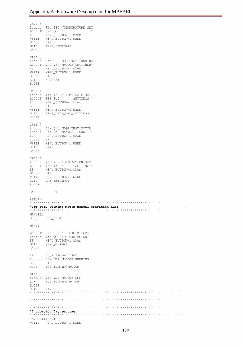
Appendix A: Firmware Development for MBFAEI
130
CASE 4 lcdout $fe,$80,"TEMPERATURE SET" LCDOUT $FE,$C0," " IF MENU_BUTTON=1 then WHILE MENU_BUTTON=1:WEND GOSUB BIP GOTO TEMP_SETTINGS ENDIF CASE 5 ' lcdout $fe,$80,"EGGTRAY TURNING" LCDOUT $FE,$c0,"MOTOR SETTINGS" IF MENU_BUTTON=1 then WHILE MENU_BUTTON=1:WEND GOSUB BIP GOTO MOT_SET ENDIF CASE 6 ' lcdout $fe,$80," TIME-DATE-DAY " LCDOUT $FE,$c0," SETTINGS " IF MENU_BUTTON=1 then GOSUB BIP WHILE MENU_BUTTON=1:WEND GOTO TIME_DATE_DAY_SETTINGS ENDIF CASE 7 ' lcdout $fe,$80,"EGG TRAY MOTOR " lcdout $fe,$c0,"MANUEL RUN " IF MENU_BUTTON=1 theN GOSUB BIP WHILE MENU_BUTTON=1:WEND GOTO MANUEL ENDIF CASE 8 ' lcdout $fe,$80,"INCUBATION DAY " LCDOUT $FE,$c0," SETTING " IF MENU_BUTTON=1 then GOSUB BIP WHILE MENU_BUTTON=1:WEND GOTO DAY_SETTINGS ENDIF END SELECT RETURN '''''''''''''''''''''''''''''''''''''''''''''''''''''''''''''''''''''''''''''''' 'Egg Tray Turning Motor Manual Operation(Run) ‘ '''''''''''''''''''''''''''''''''''''''''''''''''''''''''''''''''''''''''''''''' MANUEL: GOSUB LCD_CLEAR MANU: LCDOUT $FE,$80," PRESS <UP>" lcdout $fe,$C0,"TO RUN MOTOR " IF MENU_BUTTON=1 then GOTO MENU_CHANGE ENDIF IF UP_BUTTON=1 THEN lcdout $fe,$D4,"MOTOR RUNNING" GOSUB BIP HIGH EGG_TURNING_MOTOR ELSE lcdout $fe,$D4,"MOTOR OFF " LOW EGG_TURNING_MOTOR ENDIF GOTO MANU '''''''''''''''''''''''''''''''''''''''''''''''''''''''''''''''''''''''''''''''' '''''''''''''''''''''''''''''''''''''''''''''''''''''''''''''''''''''''''''''''' '''''''''''''''''''''''''''''''''''''''''''''''''''''''''''''''''''''''''''''''' 'Incubation Day setting '''''''''''''''''''''''''''''''''''''''''''''''''''''''''''''''''''''''''''''''' DAY_SETTINGS: WHILE MENU_BUTTON=1:WEND
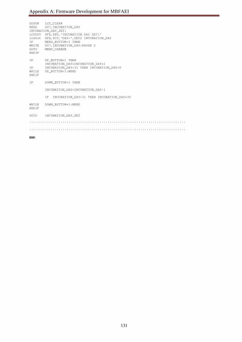
Appendix A: Firmware Development for MBFAEI
131
GOSUB LCD_CLEAR READ $07,INCUBATION_DAY INCUBATION_DAY_SET: LCDOUT $FE,$80,"INCUBATION DAY SET:" lcdout $FE,$C0,"DAY=",DEC2 INCUBATION_DAY IF MENU_BUTTON=1 THEN WRITE $07,INCUBATION_DAY:PAUSE 2 GOTO MENU_CHANGE ENDIF IF UP_BUTTON=1 THEN INCUBATION_DAY=INCUBATION_DAY+1 IF INCUBATION_DAY=31 THEN INCUBATION_DAY=0 WHILE UP_BUTTON=1:WEND ENDIF IF DOWN_BUTTON=1 THEN INCUBATION_DAY=INCUBATION_DAY-1 IF INCUBATION_DAY>31 THEN INCUBATION_DAY=30 WHILE DOWN_BUTTON=1:WEND ENDIF GOTO INCUBATION_DAY_SET '''''''''''''''''''''''''''''''''''''''''''''''''''''''''''''''''''''''''''''''' '''''''''''''''''''''''''''''''''''''''''''''''''''''''''''''''''''''''''''''''' END

Appendix B: Firmware Development for IR Remote Control based Egg Turning System
'**************************************************************** '* Name : IR Remote Control for Egg Turning System (IR Receiver) '**************************************************************** @ Device PIC12F675,WDT_ON,PWRT_ON,PROTECT_OFF,MCLR_OFF,BOD_OFF ANSEL=0 'ADC off CMCON=7 'analog comparators off DEFINE OSCCAL_1K 1 'Internal Clock Auto-Cal 'The PULSIN resolution is 10uS with PIC running at 4MHz Pulse var byte[12] Start var byte Command var byte Device var byte Counter var byte WaitForStart: 'Wait for Start signal PuLSIN GPIO.3,0,start 'Check the low pulse width if start < 180 then WaitForStart 'If the Start pulse < 1.8mS repeat the loop '''''''''''''''''''''''''''''''''''''''''''''''''''''''''''''''''''''''''' for counter=0 to 11 'Get the 12 pulses of the signal pulsin GPIO.3,0,pulse[counter] next StoreBits: command=0 device=0 for counter=0 to 6 if pulse[counter] < 90 then 'Determine if the pulse represents 0 or 1 command.0[counter] = 0 Else command.0[counter] = 1 endif next for counter=7 to 11 if pulse[counter] < 90 then device.0[counter-7] = 0 Else device.0[counter-7] = 1 endif next select case command case 0
high GPIO.1=1 ; Egg Turning Motor On case 1
high GPIO.1=0 ;Egg Turning Motor OFF case 2
high GPIO.1=1 ;Egg Turning Motor ON and OFF pause 100 high GPIO.1=0 end select pause 100 goto WaitForStart end