design and fabrication of a novel light guiding plate for backlight ...
6
HAL Id: hal-00189286 https://hal.archives-ouvertes.fr/hal-00189286 Submitted on 20 Nov 2007 HAL is a multi-disciplinary open access archive for the deposit and dissemination of sci- entific research documents, whether they are pub- lished or not. The documents may come from teaching and research institutions in France or abroad, or from public or private research centers. L’archive ouverte pluridisciplinaire HAL, est destinée au dépôt et à la diffusion de documents scientifiques de niveau recherche, publiés ou non, émanant des établissements d’enseignement et de recherche français ou étrangers, des laboratoires publics ou privés. DESIGN AND FABRICATION OF A NOVEL LIGHT GUIDING PLATE FOR BACKLIGHT SYSTEM BY MEMS TECHNOLOGY Zhi Peng Chen, Chao-Heng Chien To cite this version: Zhi Peng Chen, Chao-Heng Chien. DESIGN AND FABRICATION OF A NOVEL LIGHT GUIDING PLATE FOR BACKLIGHT SYSTEM BY MEMS TECHNOLOGY. DTIP 2006, Apr 2006, Stresa, Lago Maggiore, Italy. TIMA Editions, 5 p., 2006. <hal-00189286>
Transcript of design and fabrication of a novel light guiding plate for backlight ...
HAL Id: hal-00189286https://hal.archives-ouvertes.fr/hal-00189286
Submitted on 20 Nov 2007
HAL is a multi-disciplinary open accessarchive for the deposit and dissemination of sci-entific research documents, whether they are pub-lished or not. The documents may come fromteaching and research institutions in France orabroad, or from public or private research centers.
L’archive ouverte pluridisciplinaire HAL, estdestinée au dépôt et à la diffusion de documentsscientifiques de niveau recherche, publiés ou non,émanant des établissements d’enseignement et derecherche français ou étrangers, des laboratoirespublics ou privés.
DESIGN AND FABRICATION OF A NOVEL LIGHTGUIDING PLATE FOR BACKLIGHT SYSTEM BY
MEMS TECHNOLOGYZhi Peng Chen, Chao-Heng Chien
To cite this version:Zhi Peng Chen, Chao-Heng Chien. DESIGN AND FABRICATION OF A NOVEL LIGHT GUIDINGPLATE FOR BACKLIGHT SYSTEM BY MEMS TECHNOLOGY. DTIP 2006, Apr 2006, Stresa,Lago Maggiore, Italy. TIMA Editions, 5 p., 2006. <hal-00189286>
Stresa, Italy, 26-28 April 2006
DESIGN AND FABRICATION OF A NOVEL LIGHT GUIDING PLATE FOR BACKLIGHT
SYSTEM BY MEMS TECHNOLOGY
Chao-Heng Chien and Zhi-Peng Chen
Mechanical Engineering Department, Tatung University 40 Chung Shan N. Rd. Sec. 3 Taipei, Taiwan
ABSTRACT
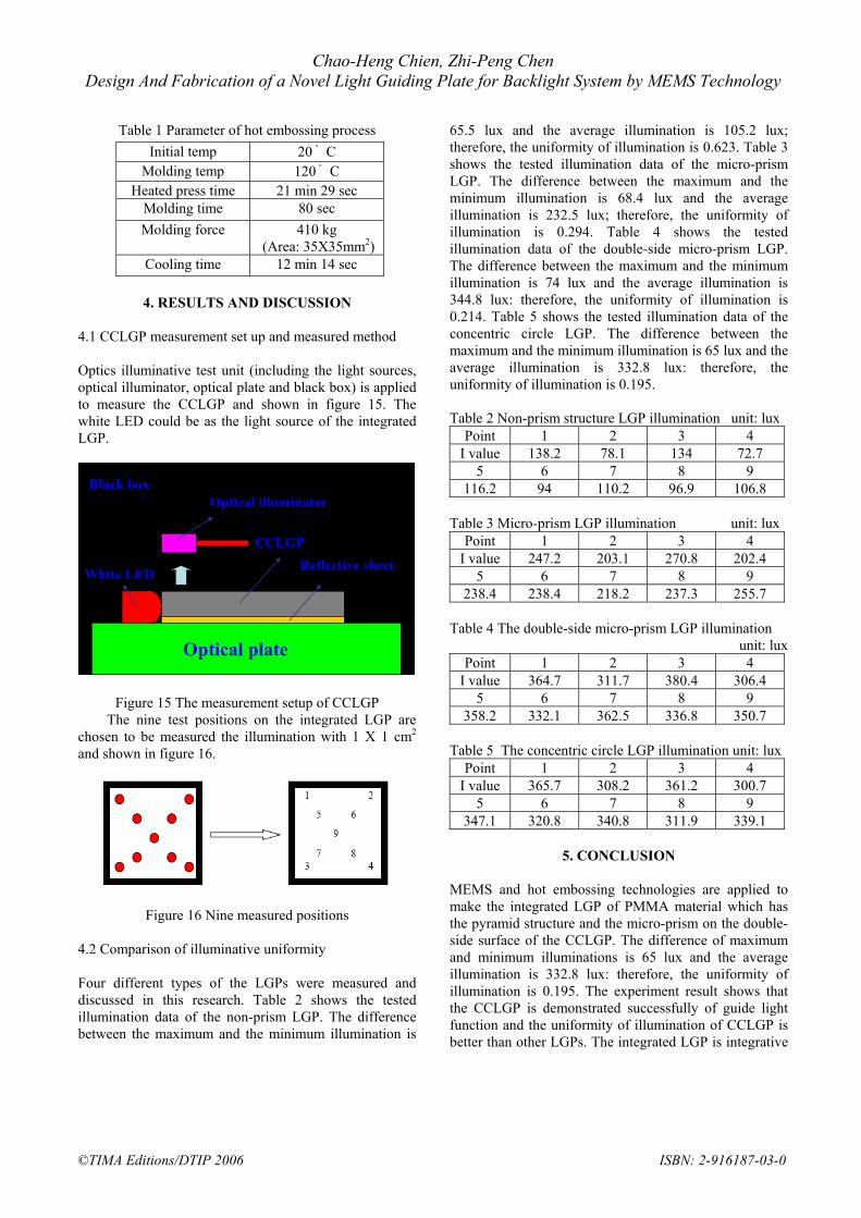
Generally, the traditional LGP is fabricated by injection molding technology. MEMS and hot embossing technologies are applied to fabricate the integrated LGP in this research. The concentric circle v-cut structure and the pyramid arrays are constructed on the integrated LGP. Therefore, the new backlight system could be simplified to use only one integrated light guiding plate without any other optical sheets. The concentric circle light guiding plate (CCLGP) can eliminate four optical sheets (including two diffusive sheets and two pyramids sheets) in backlight system, so it can save the space and the process cost of backlight system.
1. INTRODUCTION Backlight system is applied in TFT-LCD which consists of light source (as a fluorescent lamp), a light guiding plate, prism sheets, diffusive sheets and a reflective sheet. Figure 1 shows the structure of a traditional backlight mould. Following the development of the thin LCD, many researchers improve the traditional backlight modules and make it thinner, lighter, and brighter which has already become the trend. The LGP made of Polymethyl methacrylate (PMMA) material is a very important optical element in backlight system. Injection technology is applied to fabricate the traditional LGP. The diffusive points are built on the bottom of the traditional LGP which can guide light to the LCD panel actually.
In this research, the CCLGP is fabricated by using MEMS and hot-embossing technologies. The double side micro-structure is designed into the CCLGP. The v-cut structure and the pyramid structure of the CCLGP are considered to alter the direction of the light travels and to make the light emit in a direction perpendicular to the top surface of the CCLGP. A white LED is used to be light sources of the CCLGP and optical illuminator is applied to measure the optical illumination of the CCLGP. The 1.8 inch of CCLGP is designed in this research such as for mobile phones panel chosen.
Diffusive sheets
Prism sheets
Figure 1 Traditional backlight mould
2. DESIGN AND CONCEPT
The cold cathode fluorescent lamp (CCFL) was used to be the light sources of the traditional backlight system. The CCFL isn’t a green product, so a white LED is applied to be the light sources of the backlight mould in this research. The diffusive points are printed in the bottom of the traditional LGP and shown in figure 2. The output illuminative angle of the traditional LGP isn’t easy controlled, so it must be added some optical elements, including two diffusive sheets and two prism sheets and a reflective sheet; that can make the light emit in a direction perpendicular to the top surface of the traditional LGP and shown in figure 3.
Figure 2 Traditional LGP
Light guiding plate
Reflective sheet
CCFL
Diffusive points
©TIMA Editions/DTIP 2006 ISBN: 2-916187-03-0

Chao-Heng Chien, Zhi-Peng Chen Design And Fabrication of a Novel Light Guiding Plate for Backlight System by MEMS Technology
Figure 3 Traditional LGP added five optical sheets
In this research, the two micro structures are designed on the double side of the CCLGP, and are fabricated by MEMS and hot embossing technologies. The widths of the v-cut structures are designed 50 um with depth of 35.3 um and shown in figure 4. The area of the each pyramid is 50× 50 um2
on the top of CCLGP and shown in figure 5. There are three LED light sources for the traditional LGP of mobile phone. In order to use only one LED and to make the light which is distributed uniformly, the concentric distribution of v-cut and pyramid arrays are applied to fabricate the CCLGP. The input light is inserted into the surface of the v-cut structure, and then the light is reflected to the top surface of the CCLGP. The light is guided to the pyramid arrays which make the light emit in a direction perpendicular to the top surface of the CCLGP and shown in figure 6.
Figure 4 The arrangement of v-cut with width of 50um
Figure 5 The arrangement of pyramid arrays with area of 50 um2
Diffusive sheet
Pyramid sheet
Figure 6 The light guide situation of CCLGP
Reflective sheet 2.1 Design of micro structure of the LGP The design positions of the micro structures are along the circle trajectory and shown in figure 7.The concentric distribution of v-cut and pyramid structure arrays are designed by the equation 1 as:
T=rθ 1 where T: Trajectory of circle r : The distance from the light sources to the v-cut and
pyramid structures θ: The distributed varies of the micro structures with
the trajectory angle
50um
Figure 7 The concentric distribution of micro structures
100um 2.2 Material choice PMMA material with refractive index 1.5 is used to fabricate the CCLGP by MEMS and hot embossing technologies. The N-type (100) silicon mould with the micro structures of the CCLGP is etched by KOH solution which is anisotropic etchant and shown in figure 8. 50um
Figure 8 The characterization of anisotropic etching on N-type (100) silicon
50um
©TIMA Editions/DTIP 2006 ISBN: 2-916187-03-0

Chao-Heng Chien, Zhi-Peng Chen Design And Fabrication of a Novel Light Guiding Plate for Backlight System by MEMS Technology
After etching process, the silicon mould with angle is used to be the mould to make the micro structures. The relationship between the depth D and the width w could be:
2)74.54(tan 0WD = 2
3. EXPERIMENT
3.1 Fabrication procedure MEMS and hot-embossing technologies are applied to fabricate the CCLGP. The N-type (100) silicon is used to be the micro structure mould by using the anisotropic etching technology, and then silicon mould and the PMMA material is passed through the hot-embossing process. Finally, the CCLGP is completed. 3.2 Fabrication of V-cut mould The photo-resist (polyimide) is spun on the (100)-oriented silicon wafer with nitride (Si3N4) and shown in figure 9(a). After lithography process, the pattern is defined and shown in figure 9(b). The mask nitride layer is etched through reaction ion etching (RIE) technology and shown in figure 9(c). After the PR stripped, the silicon material was etched by anisotropic etching technology and the shape of the V cut is formed, as shown in figure 9(e), and then the nitride as the mask layer was removed. The v-cut mould is completed and shown in figure 9(f) and figure 10.
(a) Spin-casting
(b) Lithography process
(c) Nitride etching
(d) Unexposed-PR stripped
(e) Silicon etching
(f) V-cut mould
Figure 9 Fabrication of V-cut mould
3.3 Fabrication of Pyramid mould The first, the polyimide is spun on the (100)-oriented silicon wafer with nitride (Si3N4). After that, the pattern is defined through lithography process. RIE process is used to etch the nitride layer. After the unexposed-PR is
stripped, anisotropic etching process is applied to make pyramid mould. Finally, the pyramid mould is completed and shown in figure 11.
Figure 10 V-cut mould Figure 11 Pyramid mould
3.4 Fabrication of CCLGP PMMA material is used to fabricate the CCLGP with micro-structure on the double-side surface using hot embossing technology and shown in figure 12. PMMA is deformed through the silicon mould by hot embossing with the molding temperature up to 120 ゚ C and the clamping force 410 kg. The clamping force is kept during cooling to preserve the shrinkage of the microstructure. The operation parameter of the hot embossing process is shown in table 1. Figure 13 and figure 14 indicate the micro-prism and the micro-pyramid structures of double-side surface of the CCLGP.
Pyramid mould
PMMA materialV-cut mould
Figure 12 Hot-embossing process
Figure 13 Prism structure of CCLGP
Figure 14 Pyramid structure of CCLGP
©TIMA Editions/DTIP 2006 ISBN: 2-916187-03-0
Chao-Heng Chien, Zhi-Peng Chen Design And Fabrication of a Novel Light Guiding Plate for Backlight System by MEMS Technology
Table 1 Parameter of hot embossing process
4. RESULTS AND DISCUSSION
4.1 CCLGP measurement set up and measured method Optics illuminative test unit (including the light sources, optical illuminator, optical plate and black box) is applied to measure the CCLGP and shown in figure 15. The white LED could be as the light source of the integrated LGP.
CCLGP
Black box
White LED
Optical plate
Optical illuminator
CCLGPReflective sheet
CCLGP
Black box
White LED
Optical plate
Optical illuminator
CCLGPReflective sheet
Figure 15 The measurement setup of CCLGP The nine test positions on the integrated LGP are
chosen to be measured the illumination with 1 X 1 cm2 and shown in figure 16.
Figure 16 Nine measured positions
4.2 Comparison of illuminative uniformity
Four different types of the LGPs were measured and discussed in this research. Table 2 shows the tested illumination data of the non-prism LGP. The difference between the maximum and the minimum illumination is
65.5 lux and the average illumination is 105.2 lux; therefore, the uniformity of illumination is 0.623. Table 3 shows the tested illumination data of the micro-prism LGP. The difference between the maximum and the minimum illumination is 68.4 lux and the average illumination is 232.5 lux; therefore, the uniformity of illumination is 0.294. Table 4 shows the tested illumination data of the double-side micro-prism LGP. The difference between the maximum and the minimum illumination is 74 lux and the average illumination is 344.8 lux: therefore, the uniformity of illumination is 0.214. Table 5 shows the tested illumination data of the concentric circle LGP. The difference between the maximum and the minimum illumination is 65 lux and the average illumination is 332.8 lux: therefore, the uniformity of illumination is 0.195. Table 2 Non-prism structure LGP illumination unit: lux
Point 1 2 3 4 I value 138.2 78.1 134 72.7
5 6 7 8 9 116.2 94 110.2 96.9 106.8
Table 3 Micro-prism LGP illumination unit: lux
Point 1 2 3 4 I value 247.2 203.1 270.8 202.4
5 6 7 8 9 238.4 238.4 218.2 237.3 255.7
Table 4 The double-side micro-prism LGP illumination
unit: lux Point 1 2 3 4
I value 364.7 311.7 380.4 306.4 5 6 7 8 9
358.2 332.1 362.5 336.8 350.7 Table 5 The concentric circle LGP illumination unit: lux
Point 1 2 3 4 I value 365.7 308.2 361.2 300.7
5 6 7 8 9 347.1 320.8 340.8 311.9 339.1
5. CONCLUSION
MEMS and hot embossing technologies are applied to make the integrated LGP of PMMA material which has the pyramid structure and the micro-prism on the double-side surface of the CCLGP. The difference of maximum and minimum illuminations is 65 lux and the average illumination is 332.8 lux: therefore, the uniformity of illumination is 0.195. The experiment result shows that the CCLGP is demonstrated successfully of guide light function and the uniformity of illumination of CCLGP is better than other LGPs. The integrated LGP is integrative
Initial temp 20 ゚ C Molding temp 120 ゚ C
Heated press time 21 min 29 sec Molding time 80 sec Molding force 410 kg
(Area: 35X35mm2)Cooling time 12 min 14 sec
©TIMA Editions/DTIP 2006 ISBN: 2-916187-03-0
Chao-Heng Chien, Zhi-Peng Chen Design And Fabrication of a Novel Light Guiding Plate for Backlight System by MEMS Technology
other optics sheets in one structure, so it can reduce the process of the traditional LGP. In the future, the integrated LGP could make displays thinner and brighter for thin LCD applications.
REFERENCES [1] Di Feng, Yingbai Yan, Xingpeng Yang, Guofan Jin,
Shoushan Fan, “Novel integrated light-guide plates for liquid crystal display backlight”, Journal of Optics Applied A, IOP, UK, pp 111-117, Jan 2005.
[2] Chao-Heng Chien, Zhi-Peng Chen, “Fabrication of
Light Guiding Plates of Micro-Prism”, The 3nd conference on precision Machinery and Manufacturing Technology, Taiwan, pp 136-142, May 2005.
[3] Chao-Heng Chien, Zhi Peng Chen, “Fabrication of Light Guiding Plate of Double-Side Hot-Embossing”, MATER SCI FORUM, TTP, Switzerland, pp 211-216, Jan 2006.
[4] Chao-Heng Chien, Zhi Peng Chen, “Fabrication of integrated light Guiding Plate for backlight system”, PROCEEDINGS OF SPIE, CA USA, pp 73-80, Jan 2006.
©TIMA Editions/DTIP 2006 ISBN: 2-916187-03-0