Data sheet Actuators for 3-point control · Actuators for 3-point control ... Code No. AMV 655 24...
8
© Danfoss | 2016.04 VD.LE.S6.02 | 1 Actuators for 3-point control AMV 655 – without safety function AMV 658 SU, AMV 658 SD – with safety function (spring up/down) Data sheet Description Actuators are primarily designed to control the valve in response to the demand of a controller in District Heating/cooling, Heating, Ventilating and Air conditioning systems. Actuators AMV 655 and 658 can be controlled by electronic controllers with 3-point output. Ordering Actuators can be used without any adapter in combination with: - Valve types VFM, VFS (DN 65-100), VF (DN 100-150) and VL (DN 100) - Self-acting flow controller AFQM 6 and AFQM*. * With adapter 065B3527 for AFQM 6 or AFQM PN 25, if produced before March 2015. Used with adapter 065B3527 in combination with: - Valve types VFG(S) and VFU. Features: • Manual operation mechanical and/or electrical • Position indication, LED signalization • Selectable speed 2 or 6 s/mm • Integrated auxiliary switch • External reset button • 3-point control regulation • Thermal and overload protection • Precise control and fast response in 3-point mode (0,01 s) Main data: • Nominal voltage (AC or DC): - 24 V, 50 Hz/60 Hz - 230 V, 50 Hz/60 Hz • Control input signal: 3-point • Force: 2000 N • Stroke: 50 mm • Speed (selectable): 2 or 6 s/mm • Max. medium temperature: 200 °C Actuator Picture Type Power supply (V) Code No. AMV 655 24 082G3440 230 082G3441 AMV 658 SU 24 082G3446 230 082G3447 AMV 658 SD 24 082G3444 230 082G3445 Accessories - Stem heater Type DN Code No. Stem heater for VFM valve 65-250 065Z7022 Accessories - Adapter Type Code No. Adapter for VFG/S, VFU and AFQM 6 & AFQM PN 25 if produced before March 2015. 065B3527
Transcript of Data sheet Actuators for 3-point control · Actuators for 3-point control ... Code No. AMV 655 24...

© Danfoss | 2016.04 VD.LE.S6.02 | 1
Actuators for 3-point control AMV 655 – without safety functionAMV 658 SU, AMV 658 SD – with safety function (spring up/down)
Data sheet
Description
Actuators are primarily designed to control the valve in response to the demand of a controller in District Heating/cooling, Heating, Ventilating and Air conditioning systems.
Actuators AMV 655 and 658 can be controlled by electronic controllers with 3-point output.
Ordering
Actuators can be used without any adapter in combination with:- Valve types VFM, VFS (DN 65-100), VF (DN 100-150) and VL (DN 100)- Self-acting flow controller AFQM 6 and AFQM*. * With adapter 065B3527 for AFQM 6 or AFQM PN 25, if produced before March 2015. Used with adapter 065B3527 in combination with:- Valve types VFG(S) and VFU.
Features:• Manual operation mechanical and/or electrical• Position indication, LED signalization• Selectable speed 2 or 6 s/mm• Integrated auxiliary switch• External reset button• 3-point control regulation• Thermal and overload protection• Precise control and fast response in 3-point
mode (0,01 s)
Main data:• Nominal voltage (AC or DC):
- 24 V, 50 Hz/60 Hz- 230 V, 50 Hz/60 Hz
• Control input signal: 3-point• Force: 2000 N• Stroke: 50 mm• Speed (selectable): 2 or 6 s/mm• Max. medium temperature: 200 °C
Actuator
Picture Type Power supply(V) Code No.
AMV 65524 082G3440
230 082G3441
AMV 658 SU24 082G3446
230 082G3447
AMV 658 SD24 082G3444
230 082G3445
Accessories - Stem heaterType DN Code No.
Stem heater for VFM valve 65-250 065Z7022
Accessories - AdapterType Code No.
Adapter for VFG/S, VFU and AFQM 6 & AFQM PN 25 if produced before March 2015. 065B3527

Data sheet Actuators for 3-point control AMV 655/658/659
2 | © Danfoss | 2016.04 VD.LE.S6.02
Actuator type AMV 655 AMV 658 SD AMV 658 SU
Power supply V 24 or 230 ; +10 … –15 % ; AC or DC
Power consumption VA 14,4 (24 V)16,1 (230 V)
19,2 (24 V)35,7 (230 V)
19,2 (24 V)35,7 (230 V)
Frequency Hz 50/60
Control input 3-point
Closing force N 2000
Max. stroke mm 50
Speed (selectable) s/mm 2 or 6
Max. medium temperature
°C
200 (350 with extension piece for VFGS valve)
Ambient temperature 0 … + 55
Storage and transport temperature −40 … +70 (storing for 3 days)
Humidity 5-95% (no condensing)
Protection class II
Grade of enclosure IP 54
Weight kg 5,3 8,6 8,6
Safety function - Yes Yes
Safety function runtime/50 mm stroke s - 120 120
Manual operation Mechanical Electrical and mechanical
Electrical and mechanical
Power failure response Stem remains in last position
Safety function extracts the stem
Safety function retracts the stem
– marking in accordance with the standards
Low Voltage Directive 2006/95/EECEMC Directive 2004/108/EEC
The actuator must be dismantled and the elements sorted into various material groups before disposal.
Before disassembly please contact Danfoss support for disassembly instructions.
Disposal
Complete the mechanical and electrical installation (see instructions) and perform the necessary checks and tests:
- Turn on the power- Set the appropriate control signal and check
that the valve stem direction is correct for the application.
The unit is now fully commissioned.
Commissioning
Technical data
Please check power supply and power consumption prior connection!
Data sheet Actuators for 3-point control AMV 655/658/659
© Danfoss | 2016.04 | 3VD.LE.S6.02
VFU 2 + adapter 065B3527 VFU 2 + adapter 065B3527 + ZF4/5
VFG/S + adapter 065B3527 VFG/S + adapter 065B3527 + ZF4/5VFG/S + adapter 065B3527
VFU 2 + adapter 065B3527
>120°C200-300°C ZF4200-350°C ZF5
<120°C >120°C 200-300°C ZF4200-350°C ZF5
<120°C
Installation
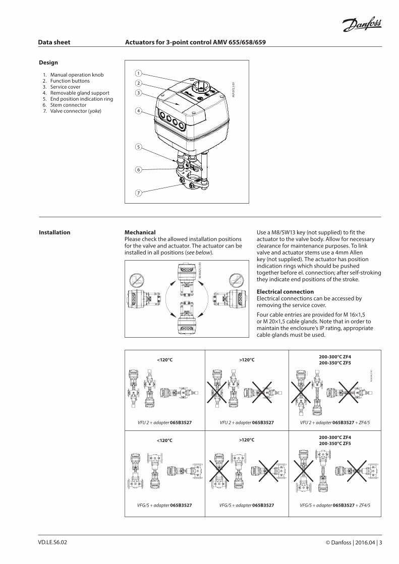
Design
1. Manual operation knob 2. Function buttons 3. Service cover 4. Removable gland support 5. End position indication ring 6. Stem connector 7. Valve connector (yoke)
Mechanical Please check the allowed installation positions for the valve and actuator. The actuator can be installed in all positions (see below).
Use a M8/SW13 key (not supplied) to fit the actuator to the valve body. Allow for necessary clearance for maintenance purposes. To link valve and actuator stems use a 4mm Allen key (not supplied). The actuator has position indication rings which should be pushed together before el. connection; after self-stroking they indicate end positions of the stroke.
Electrical connection Electrical connections can be accessed by removing the service cover.
Four cable entries are provided for M 16×1,5 or M 20×1,5 cable glands. Note that in order to maintain the enclosure’s IP rating, appropriate cable glands must be used.
Data sheet Actuators for 3-point control AMV 655/658/659
4 | © Danfoss | 2016.04 VD.LE.S6.02
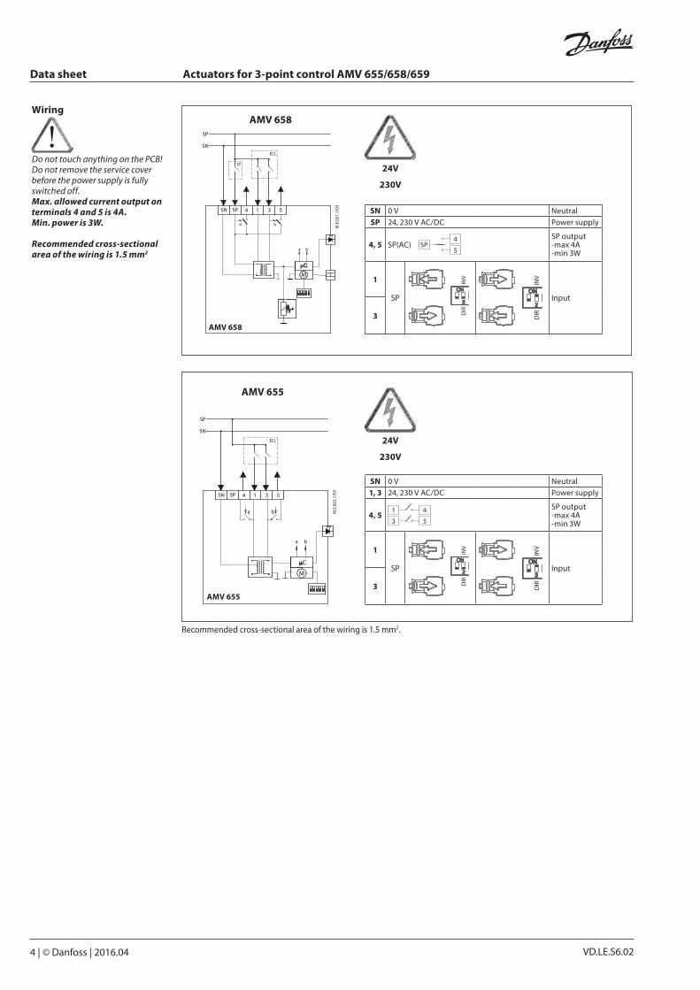
AMV 655
AMV 655
SN 0 V NeutralSP 24, 230 V AC/DC Power supply
4, 5 SP(AC)4
5SP
SP output-max 4A -min 3W
1
SP
Input
3
AMV 658
AMV 658
24V
230V
24V
230V
SN 0 V Neutral1, 3 24, 230 V AC/DC Power supply
4, 54
5
1
3
SP output-max 4A -min 3W
1
SP
Input
3
Recommended cross-sectional area of the wiring is 1.5 mm2.
Wiring
Do not touch anything on the PCB! Do not remove the service cover before the power supply is fully switched off.Max. allowed current output on terminals 4 and 5 is 4A. Min. power is 3W.
Recommended cross-sectional area of the wiring is 1.5 mm2

Data sheet Actuators for 3-point control AMV 655/658/659
© Danfoss | 2016.04 | 5VD.LE.S6.02
LED operating mode indicatorThe three-colour (green/yellow/red) LED function indicators are located on the actuator cover. They indicate different operating modes.
RESET button (versions AMV 658)Actuators AMV 658 have external RESET button which is located on top cover of the actuator next to LED indicators. With this button you can enter or exit Stand-By mode (press once) See next paragraph for mode details.
Operating modes• Stand-By mode (versions AMV 658)
Press the RESET button for 1 sec. to enter Stand-By mode. The actuator stops in current position and stops responding to any control signal. Red light is constantly lit. You can manually operate the actuator with mechanical handle (version AMV 655/658) or control buttons (versions AMV 658). This mode can be very useful during the commissioning of other equipment, or for service purposes. To exit Stand-By mode press the RESET button again.
• Positioning mode The actuator is operating automatically. The stem is extending or retracting according to the control signal. When positioning is finished the actuator goes to Stationary mode.
• Stationary mode The actuator is operating without errors.
• Error mode Working temperature is too high - check the ambient temperature.
Stroke is too short - check the connection with valve and valve operation or check if valve is blocked.
LED indication for AMV 655/658
NOTE! LED signalling is a direct indicator of the signal from controller therefore lengths of LED indication can vary and sometimes even look like a short flash if the controlling signal is present for a very short period.
Actuator type AMV 655 doesn’t have constant power supply and operates only when the controller provides a signal. Therefore limited LED indication possibilities are available.
LED Indication type Operating mode Actuator type
Green
Constantly lit Positioning mode - Actuator is retracting the stem
AMV 655AMV 658
Constantly lit Positioning mode - Actuator is extending the stem
AMV 655AMV 658
Yellow
Constantly lit Stationary mode - Actuator has reached upper end position (retracted stem)
AMV 655AMV 658
Constantly lit Stationary mode - Actuator has reached bottom end position (extending stem)
AMV 655AMV 658
Flashing Stationary mode AMV 658
Red
Constantly lit Stand - By mode AMV 658
Flashing Error ModeAMV 655AMV 658
Dark No indicationNo power supply
AMV 655AMV 658
No control signal AMV 655
Actuator operating modes
LED signalling

Data sheet Actuators for 3-point control AMV 655/658/659
6 | © Danfoss | 2016.04 VD.LE.S6.02
A
A
B
B
1
SP
3
1
SP
3
DIP switch setting The actuator has a selection of DIP switches (Fig. 1) under the service cover.
DIP1: FAST/SLOW – Speed selection - FAST; 2 s/mm- SLOW; 6 s/mm
DIP2: DIR/INV – Direct or inverse actingselector (Fig. 2):- DIR position; the actuator is direct acting to
input signal.- INV position; the actuator is (reverse) inverse
acting to input signal.
Fig. 2
Fig. 1
Actuator type Mechanical operation
Electrical operation
AMV 655
AMV 658 The actuator AMV 655 can be manually positioned and remains in selected position until it receives signal from the controller.The actuator AMV 658 can be manually positioned when in Stand-By mode or when there is no power supply (mechanically).
Mechanical manual operationActuators AMV 655/658 have a knob & crank on the top of the housing which enables hand positioning of the actuator.
Use Mechanical manual operation only when the power is disconnected.
Electrical manual operationThe actuator AMV 658 has two buttons on the top of the housing that are used for electrical manual positioning (up or down) if the actuator is in Stand-By mode. First press the RESET button until the actuator goes to Stand-By mode (red LED is lit). By pressing the upper button the stem will be extending and by pressing the lower button the stem will be retracted.
Mechanical and electrical operation are not allowed to be used at the same time!
Manual operation

Data sheet Actuators for 3-point control AMV 655/658/659
© Danfoss | 2016.04 | 7VD.LE.S6.02
AMV 65x + AFQM PN 16 (DN 65-125)
AMV 65x + AFQM 6 *
AMV 65x + VFG(S) 2 +adapter:
065B3527 (DN 15-250)
AMV 65x + VFM 2
AMV 65x + VF 2 (DN 100-150)
VL 2 (DN 100) VFS 2 (DN 65-100)
AMV 65x + VF 3 (DN 100-150)
VL 3 (DN 100)
AMV 65x + VFG 3 +
adapter: 065B3527 (DN 25-125)
AMV 65x + VFU +
adapter: 065B3527 (DN 15-125)
AMV 65x + AFQM PN 25 *
* Please use adapter 065B3527 for combination with AFQM PN25 & AFQM 6 if produced before March 2015.
Actuator – valves combinations

VD.LE.S6.028 | © Danfoss | DHS-SRMT/SI | 2016.04
Danfoss can accept no responsibility for possible errors in catalogues, brochures and other printed material. Danfoss reserves the right to alter its products without notice. This also applies to products already on order provided that such alterations can be made without subsequential changes being necessary eady agreed.All trademarks in this material are property of the respective companies. Danfoss and the Danfoss logotype are trademarks of Danfoss A/S. All rights reserved.
Data sheet Actuators for 3-point control AMV 655/658/659
Min
. 450
186
191
369
353
Dimensions