CVSeries Process Control Valves - Control Center INCcontrolcentertn.com/images/new1/T3 valves.pdfThe...
12
CV Series Process Control Valves
Transcript of CVSeries Process Control Valves - Control Center INCcontrolcentertn.com/images/new1/T3 valves.pdfThe...

CVSeriesProcess ControlValves

The CVE’s innovative design makes it among themost versatile process control valves in the world.
Its cage-guided Kwik-Change Trim® utilizes multi-interchangeable trim styles, eliminating the need tochange body style.
The CVE Series Process Control Valves are availablewith balanced or un-balanced trim for oil, gas, chemical,power and refining applications. Body styles includeboth globe and angle configurations with a choice offlanged, buttweld, or threaded connections.
SERIES CVE
PROCESS CONTROL VALVE
T3 Energy Services high pressure globe style control valves arein accordance with the following standards.
Flanged Connections: ANSI - B16.5 / API 6AISA - S75.16
Butt Weld Connections: ISA - S75.16Socket Weld Connections: ISA - S75.16Screwed Connections: ISA - S75.16
1.800.314.4753

SERIES CVE
SINGLE SEATED GLOBE CONTROL VALVES
CVES CVETCVEDCVEZ
The CVES trim design isun-balanced and cage guidedwith cage profiled flow charac-teristics. With optional shutoffclasses IV, V and VI, this designis used over a wide range of tem-peratures and pressures in a mul-titude of clean services.
The CVEZ trim design isun-balanced with rugged “post-guiding” and plug profiled flowcharacteristics. Offering shutoffclasses IV, V and VI, this designis especially suited for erosive,viscous or particle contaminatedfluids and in “low flow” applica-tions.
The CVED trim design isbalanced* and cage guided withcage profiled flow characteris-tics. Standard class II shutoff,with class III and IV optional.The CVED is designed for useover a wide range of pressuresand temperatures in clean fluids,gases and/or vapors.
*Balanced trims substantially
reduce actuator thrust
requirements.
The CVET trim design is amodified version of the CVED
model. Standard class IV and Vshutoff is achieved with anupgraded plug seal ring and a“soft seat” insert. Metal seating isoptional. Maximum tempera-ture limit is 450°F.
FEATURES
• 100% materials traceability• High flow capacity• Internal parts interchangeability• Low recovery trims available to combine multi-state pressure reduction and velocity control• Wide range of material options• Top entry facilitates ease of parts removal and maintenance
SPECIFICATIONS:
Size: 1” to 8” nominal boreBody styles: Through globe and angleBonnets: Standard, normalizing, bellows seal and cryogenic bonnets are supplied to suit
application requirementsRatings: ANSI Class 150 to 600Connections: ANSI RF or RTJ flanged, screwed through 2”, welding ends as specified - butt weld
or socketValve Trim: CVES, CVED & CVET - cage guided, balanced or unbalanced in single or
multi-stage designCVEZ - post guided, and unbalanced. Low recovery trim options available
Characteristics: Linear, equal percentage, or quick openAccessories: Steam jackets. Purging Assemblies.
1.800.314.4753

FEATURES:• 100% Materials Traceability• Economic alternative for standard or severe services.• Trim options for erosive service.• Design flexibility.• Top entry allows ease of repair and maintenance.• End connections accommodate ANSI & API pressure ratings.• Wide range of material options.
SPECIFICATIONS:
Size: 1” and 2” nominal bore.Body Styles: Through globe or angle with screwed-on bonnet.Bonnets: Standard bonnets are supplied to suit application requirements to 450°F.Ratings: ANSI Class 150 through 1500; API 2000 and 3000.Connections: ANSI and API flanges. Screwed connections. Welding ends as specified -
butt weld or socket.Valve Trims: Unbalanced Micro-Form, Micro-Flow, and Micro-Flute. Micro-Form available in seat
sizes up to 1-1/4” nominal bore. Severe service and erosion resistant trims available to suit applications.
Characteristics: Linear, Equal Percentage, or Quick Open.
The CVD Globe Control Valves are designed for many standard andsevere service application in most process control industries includingPower Generation, Petrochemical Production and Refining.
The design is of simple construction with a top-entry screwedbody/bonnet arrangement. The valve plug has heavy duty post guiding with screwed-in seat. These features allow ease of repair and maintenance.
The CVD Series valves are especially suited for erosive service conditions and viscous or particle contaminated fluids.
SERIES CVD
SINGLE SEATED GLOBE CONTROL VALVES
SERIES CVD
1.800.314.4753

SERIES CVHG
FEATURES:• 100% Materials Traceability• High integrity pressure containment.• Forged body facilitates high pipe stress, eliminating distortion.• Low recovery trims available to combine multi-stage pressure reduction and velocity control.• A wide range of material options are readily available which reduces lead times normally
encountered with high pressure casting.
SPECIFICATIONS:
Size: 1” to 8” nominal bore.Body Styles: Through globe and angle.Bonnets: Standard, normalizing, bellows seal and cryogenic bonnets are supplied to suit
application requirements.Ratings: ANSI 150 to 4500; API 2000# to 15,000#.Connections: ANSI and API flanges. Screwed connections. Welding ends as specified -
butt weld or socket.Valve Trims: Ported cage, low recovery cage, solid or balanced in single or multi-stage design.Characteristics: Linear, Equal Percentage, or Quick Open.Accessories: Removable blindheads; steam jackets; purging assemblies.
SERIES CVHA
SERIES CVHHIGH DUTY SINGLE SEATED GLOBE VALVES
The CVHG Control Valvesare designed for high duty appli-cations in most Process ControlIndustries, including PowerGeneration, PetrochemicalProduction and Refining. Theoverall construction of the SeriesCVHG provides a high perform-ance concept capable of extend-ing many standard variationsinto specialized applications.
The forged body ensures highmaterial integrity and is propor-tioned to withstand high stresseswithout distortion.
1.800.314.4753
SERIES CVYD AND CVYSTHREE-WAY GLOBE CONTROL VALVES
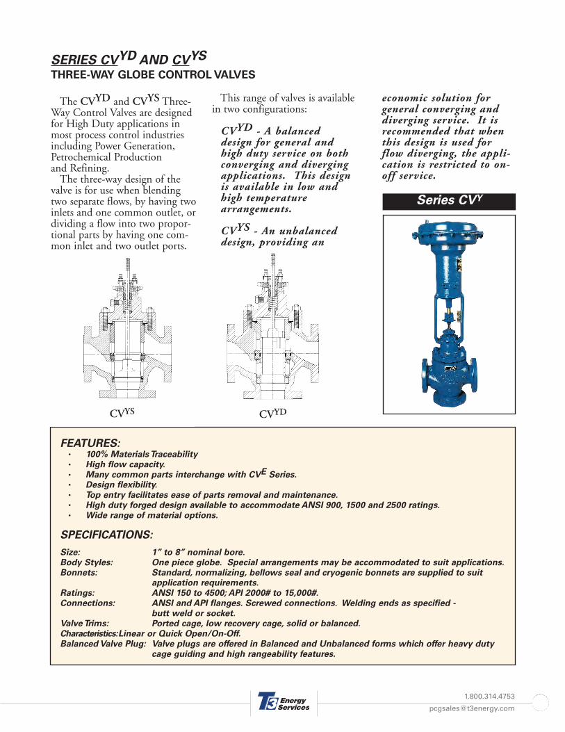
The CVYD and CVYS Three-Way Control Valves are designedfor High Duty applications inmost process control industriesincluding Power Generation,Petrochemical Production and Refining.
The three-way design of thevalve is for use when blendingtwo separate flows, by having twoinlets and one common outlet, ordividing a flow into two propor-tional parts by having one com-mon inlet and two outlet ports.
This range of valves is availablein two configurations:
CVYD - A balanceddesign for general andhigh duty service on bothconverging and divergingapplications. This designis available in low andhigh temperaturearrangements.
CVYS - An unbalanceddesign, providing an
economic solution forgeneral converging anddiverging service. It isrecommended that whenthis design is used forflow diverging, the appli-cation is restricted to on-off service.
FEATURES:• 100% Materials Traceability• High flow capacity.• Many common parts interchange with CVE Series.• Design flexibility.• Top entry facilitates ease of parts removal and maintenance.• High duty forged design available to accommodate ANSI 900, 1500 and 2500 ratings.• Wide range of material options.
SPECIFICATIONS:
Size: 1” to 8” nominal bore.Body Styles: One piece globe. Special arrangements may be accommodated to suit applications.Bonnets: Standard, normalizing, bellows seal and cryogenic bonnets are supplied to suit
application requirements.Ratings: ANSI 150 to 4500; API 2000# to 15,000#.Connections: ANSI and API flanges. Screwed connections. Welding ends as specified -
butt weld or socket.Valve Trims: Ported cage, low recovery cage, solid or balanced.Characteristics:Linear or Quick Open/On-Off.Balanced Valve Plug: Valve plugs are offered in Balanced and Unbalanced forms which offer heavy duty
cage guiding and high rangeability features.
Series CVY
CVYS CVYD
1.800.314.4753

SERIES CV CRYO
CRYOGENIC CONTROL VALVES
T3 Energy Services manufac-tures a range of specialized auto-matic and manual control valvesfor cryogenic service. The experi-ence of the engineering staff inthe field of cryogenic design hasled to the development of variousconstructions to suit the majorityof applications.
The basic cryogenic bonnetdesign may be modified forinstallation into fabricated ‘coldbox’ units.
Two main features of the T3Energy Services extended bonnetsfor cryogenic applications includethe capability of removing thevalve ‘topworks’ from outside a
‘cold-box’ to withdraw the plugand stem assembly for inspectionand the inclusion of PTFE spoolswith carefully machined labyrinthgrooves and vapor pockets toreduce heat transfer by conduc-tion.
Series CVCRYO
FEATURES:• Overall weight kept to a minimum to reduce vaporization during plant start-up.• Stem sealing takes place in purpose designed vapor pockets to maximize efficiency.• Design flexibility.• Modular construction accommodates most installations.• Low recovery trims combine multi-stage pressure reduction and velocity control.• Selection of material options given to minimize heat transfer by conduction.
SPECIFICATIONS:
Size: 1” to 8” nominal bore.Body Styles: Through globe and angle.Bonnets: Cryogenic bonnets are supplied to suit application requirements.Ratings: ANSI 150 to 4500.Connections: ANSI flanges; welding ends as specific - butt weld or socket.Valve trims: Ported cage, low recovery cage, solid or balanced in single or multi-stage designCharacteristics: Linear, Equal Percentage, or Quick Open.
COLD BOX WALL
PTFE SPOOLS
LABYRINTH GROOVES
VAPOR POCKETS
DIMENSION TOCENTER LINE OFVALVE MAY BE
ADJUSTED TO SUITINSTALLATION
1.800.314.4753

SERIES CV EF
HIGH DUTY GLOBE AND ANGLE VALVES
The CVEF series controlvalve utilizes all of the Kwik-Change® internal parts of theCVE series but in a “Fabricated”body and bonnet. A wide rangeof “bar Stock” or forged materialsare readily available whichreduces lead times normallyencountered with castings.
CVEF Control Valves areavailable in “Balanced”* or“Unbalanced” plug designs forapplication in most ProcessControl Industries includingPower Generation, PetrochemicalProduction and Refining. Body styles include throughglobe and angle configurations
with a choice of flanged, but-tweld or threaded connections.
*Balanced trims substantially reduce cactuator thrust requirements.
Series CVEF
FEATURES:
• 100% Materials Traceability• Parts interchangeability with the CVE Series• High integrity pressure containment• A wide range of Forged or “Bar Stock” material options• Low recovery “Anti-Cavitation” and “Low Noise” trims available• Top Entry facilitates ease of parts removal and maintenance
SPECIFICATIONS:
Size: 1/2” to 4” nominal bore (Consult Factory for other sizes).Body Styles: Through globe and angle.Bonnets: Standard, normalizing, bellows seal and cryogenic.Ratings: ANSI Class 150 to 600 (See CVHG for higher pressure ratings).Connections: ANSI RF or RTJ flanged, threaded through 2”, buttweld or socket.Valve trims: Cage Guided Balanced or Un-balanced, Post Guided Un-balanced.Characteristics: Linear, Equal Percentage, or Quick Open.
CVEF CVEFA
1.800.314.4753

SERIES CVH-S
, CVH-M
, CVH-L
MANUAL OPERATED ACTUATOR
The Series CVH Manual Operated Actuator is used when onlydirect manual operation is required. Control valves are positionedprecisely and an indicator is provided to show valve position and travel.
The handwheel operates through a revolving nut mechanism, whichengages with a lead screw. An anti-twist device is incorporated intothe basic design to provide linear motion.
Low friction thrust bearings ensure ease of operation throughoutthe valve travel. The actuator stem is positively coupled directly tothe valve stem by a split connector.
FEATURES:
• High power.• Positive stem connector, split for ease of attachment.• Spring-loaded detent action ball built into handwheel • prevents movement due to vibration.• Rigid iron and steel construction.• Stainless Steel travel indicator and scale.
SPECIFICATIONACTUATOR SIZE
CVH-S CVH-M CVH-L
YOKE BOSS DIAMETER(Inches)
2-1/8 2-13/16 3-9/16
ACTUATOR STEM SIZE(Inches)
0.75 0.75 1.125
STANDARD VALVE STEMSIZE (Inches)
0.375 0.5 0.75
MAXIMUM THRUST*(Pounds per foot)
4200 6000 6000
MAXIMUM TRAVEL(Inches)
1-1/8 2 & 3 3 & 5
APPROXIMATE WEIGHTS(Pounds)
44 52 84
*Recommended thrust with 60 lbs.f max. turning force.
Series CVH
1.800.314.4753
1.800.314.4753
SERIES CVD and CVR
DIRECT & REVERSE ACTING DIAPHRAGM ACTUATOR
FEATURES:• High power.• Fast response, excellent stability, and low hysteresis.• Design flexibility - a wide range of size, travel, and spring options.• Positive stem connector, split for ease of attachment.• Stainless steel actuator stem; friction bearings for spring adjustment are standard features.
SPECIFICATIONS:
Size: 45S, 59S. 59M, 87M, 87L, 169M, 169L.Styles: CVD - Direct acting (Fail Up);
CVR - Reverse acting (Fail Down).Travel Indication: Stainless steel disc and graduated scale.
Accessories: Top-mounted handwheelSide-mounted handwheelMaximum / minimum limit stopsSnubbers
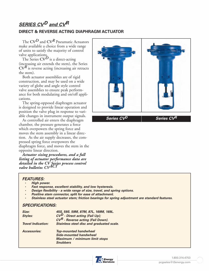
Series CVD Series CVR
The CVD and CVR Pneumatic Actuatorsmake available a choice from a wide rangeof units to satisfy the majority of controlvalve applications.
The Series CVD is a direct-acting(increasing air extends the stem), the SeriesCVR is reverse acting (increasing air retractsthe stem).
Both actuator assemblies are of rigid construction, and may be used on a widevariety of globe and angle style controlvalve assemblies to ensure peak perform-ance for both modulating and on/off appli-cations.
The spring-opposed diaphragm actuatoris designed to provide linear operation andposition the valve plug in response to vari-able changes in instrument output signals.
As controlled air enters the diaphragmchamber, the pressure generates a forcewhich overpowers the spring force andmoves the stem assembly in a linear direc-tion. As the air supply decreases, the com-pressed spring force overpowers thediaphragm force, and moves the stem in theopposite linear direction.
Actuator sizing procedures, and a fulllisting of actuator performance data aredetailed in the CV Series process controlvalve bulletin: CVACT

SPECIFICATIONACTUATOR SIZE
45S 59S 59M 87M 87L 169M 169L 240L
NOMINAL EFFECTIVE AREA(Square Inches)
45 59 59 87 87 169 160 240
YOKE BOSS DIAMETER(Inches)
2-1/8 2-1/8 2-13/16 2-13/16 3-9/16 2-13/16 3-9/16 3-9/16
ACTUATOR STEM SIZE(Inches)
3/4 3/4 3/4 3/4 1-1/8 3/4 1-1/8 1-1/8
VALVE STEM SIZE(Inches)
0.375 0.375 0.5 0.5 0.75 0.5 0.75 0.75
MAXIMUM THRUST(Pounds per foot)
2025 2655 2655 4350 4350 7605 7605 9600
MAXIMUM CONTINUOUSW.P. (PSIG)
60 60 60 65 65 60 60 55
MAXIMUM TRAVEL(Inches)
3/4 1-1/8 1-1/2 2 2 3 3 4
APPROXIMATE WEIGHTS(Pounds)
34 48 50 90 94 121 122 175
PRESSURE CONNECTIONS1/4" NPT STANDARD
LARGER SIZES AVAILABLE
CVD CVR
1.800.314.4753

Flow Control Equipment,Manufacturing & Service Center103 Venture Blvd. Houma, LA 70360
Phone: (985) 851-3160 Fax: (985) 851-5102E-Mail: [email protected]