Crystallite size and strain calculations of hard particle ...
13
Proceedings of the Estonian Academy of Sciences, 2019, 68, 1, 66–78 https://doi.org/10.3176/proc.2019.1.02 Available online at www.eap.ee/proceedings Crystallite size and strain calculations of hard particle reinforced composite powders (Cu/Ni/Fe–WC) synthesized via mechanical alloying Aydın Şelte * and Burak Özkal Department of Metallurgy and Materials Engineering, Chemical & Metallurgical Engineering Faculty, Istanbul Technical University, 34469 Maslak, Istanbul, Turkey Received 18 May 2018, accepted 2 October 2018, available online 25 January 2019 © 2018 Authors. This is an Open Access article distributed under the terms and conditions of the Creative Commons Attribution- NonCommercial 4.0 International License (http://creativecommons.org/licenses/by-nc/4.0/). Abstract. In this study, Cu–25WC, Ni–25WC, and Fe–25WC (all in wt%) composite powders were produced via mechanical alloying (MA) and characterized for their potential utilization in particulate materials based technologies. The changes in the crystallite size (D) and lattice strain (ε) during the production of WC particle reinforced Cu, Fe, and Ni composite powders via MA were investigated. The Williamson–Hall (W–H) plot analysis and fundamental parameters approach (FPA) applied with Lorentzian function were used to evaluate ε and D of matrix phases from XRD results. With increasing MA, ε values of all matrix phases showed an increase whereas D values showed a decrease. In addition to that, lattice parameters a Cu and a Ni changed linearly with time, and a Fe displayed a slight decrease. The XRD peak belonging to the Cu (111) plane shifted towards larger 2-theta angles in the same direction. Contrary to Cu, the Fe (110) peak shifted to lower angles with MA time. However, the XRD peak belonging to the Ni (111) plane changed alternately. Similar results were obtained from both W–H plot analysis and the FPA calculations. Minimum crystallite size and maximum internal strain rates were estimated for 8 h MA’ed Cu25WC, Fe25WC, and Ni25WC composite powders as 14.63 nm and 1.39%, 7.60 nm and 1.23%, and 17.65 nm and 1.13%, respectively. Transmission electron microscope observations were found in good agreement with the crystallite size of XRD calculations. Key words: transition elements, tungsten carbide, mechanical alloying, nanocrystalline materials, Williamson–Hall method, Lorentzian function. 1. INTRODUCTION * Hard particle reinforced materials have been considered as candidate materials for the engineering applications where both high strength and high abrasion resistance are demanded. Considering the recent developments and the level of interest for additive manufacturing, it is clear that expanding the current powder types and their compositions is necessary. Since mixed powders have certain handicaps like powder state segregation due to size and density differences among individual particles, the concept of composite powders apparently enlarges * Corresponding author, [email protected] the current lane by bringing together the dissimilar material compositions into one single particle which is difficult or practically impossible via conventional metallurgical practices [1,2]. There are different possibilities of the production of composite powders and most of them need to be optimized for each case to meet with the targeted composition. On the other hand, mechanical alloying (MA) emerges as an easy alternative method for the production of composite powders, especially for the lab scale quantities having a desired level of chemical homogeneity and micrometre- to ultrafine-sized powder fractions. It is also a top-down strategy frequently applied by scientists in the production of nanostructured
Transcript of Crystallite size and strain calculations of hard particle ...

Proceedings of the Estonian Academy of Sciences, 2019, 68, 1,
Proceedings of the Estonian Academy of Sciences, 2019, 68, 1, 66–78
https://doi.org/10.3176/proc.2019.1.02 Available online at www.eap.ee/proceedings
Crystallite size and strain calculations of hard particle reinforced composite powders (Cu/Ni/Fe–WC) synthesized via mechanical alloying
Aydın Şelte* and Burak Özkal
Department of Metallurgy and Materials Engineering, Chemical & Metallurgical Engineering Faculty, Istanbul Technical University, 34469 Maslak, Istanbul, Turkey Received 18 May 2018, accepted 2 October 2018, available online 25 January 2019 © 2018 Authors. This is an Open Access article distributed under the terms and conditions of the Creative Commons Attribution-NonCommercial 4.0 International License (http://creativecommons.org/licenses/by-nc/4.0/). Abstract. In this study, Cu–25WC, Ni–25WC, and Fe–25WC (all in wt%) composite powders were produced via mechanical alloying (MA) and characterized for their potential utilization in particulate materials based technologies. The changes in the crystallite size (D) and lattice strain (ε) during the production of WC particle reinforced Cu, Fe, and Ni composite powders via MA were investigated. The Williamson–Hall (W–H) plot analysis and fundamental parameters approach (FPA) applied with Lorentzian function were used to evaluate ε and D of matrix phases from XRD results. With increasing MA, ε values of all matrix phases showed an increase whereas D values showed a decrease. In addition to that, lattice parameters aCu and aNi changed linearly with time, and aFe displayed a slight decrease. The XRD peak belonging to the Cu (111) plane shifted towards larger 2-theta angles in the same direction. Contrary to Cu, the Fe (110) peak shifted to lower angles with MA time. However, the XRD peak belonging to the Ni (111) plane changed alternately. Similar results were obtained from both W–H plot analysis and the FPA calculations. Minimum crystallite size and maximum internal strain rates were estimated for 8 h MA’ed Cu25WC, Fe25WC, and Ni25WC composite powders as 14.63 nm and 1.39%, 7.60 nm and 1.23%, and 17.65 nm and 1.13%, respectively. Transmission electron microscope observations were found in good agreement with the crystallite size of XRD calculations. Key words: transition elements, tungsten carbide, mechanical alloying, nanocrystalline materials, Williamson–Hall method, Lorentzian function. 1. INTRODUCTION * Hard particle reinforced materials have been considered as candidate materials for the engineering applications where both high strength and high abrasion resistance are demanded. Considering the recent developments and the level of interest for additive manufacturing, it is clear that expanding the current powder types and their compositions is necessary. Since mixed powders have certain handicaps like powder state segregation due to size and density differences among individual particles, the concept of composite powders apparently enlarges * Corresponding author, [email protected]
the current lane by bringing together the dissimilar material compositions into one single particle which is difficult or practically impossible via conventional metallurgical practices [1,2].
There are different possibilities of the production of composite powders and most of them need to be optimized for each case to meet with the targeted composition. On the other hand, mechanical alloying (MA) emerges as an easy alternative method for the production of composite powders, especially for the lab scale quantities having a desired level of chemical homogeneity and micrometre- to ultrafine-sized powder fractions. It is also a top-down strategy frequently applied by scientists in the production of nanostructured
A. Şelte and B. Özkal: Crystallite size and strain of composite powders
67
materials by decreasing crystallite sizes and additionally usually having amorphous or metastable phases in the powder state which is capable of ending with nanograined materials after sintering [3].
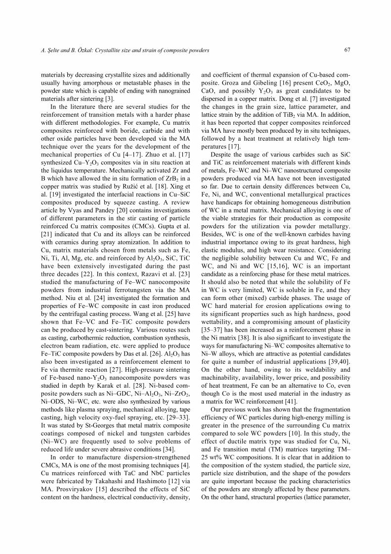
In the literature there are several studies for the reinforcement of transition metals with a harder phase with different methodologies. For example, Cu matrix composites reinforced with boride, carbide and with other oxide particles have been developed via the MA technique over the years for the development of the mechanical properties of Cu [4–17]. Zhuo et al. [17] synthesized Cu–Y2O3 composites via in situ reaction at the liquidus temperature. Mechanically activated Zr and B which have allowed the in situ formation of ZrB2 in a copper matrix was studied by Ružić et al. [18]. Xing et al. [19] investigated the interfacial reactions in Cu–SiC composites produced by squeeze casting. A review article by Vyas and Pandey [20] contains investigations of different parameters in the stir casting of particle reinforced Cu matrix composites (CMCs). Gupta et al. [21] indicated that Cu and its alloys can be reinforced with ceramics during spray atomization. In addition to Cu, matrix materials chosen from metals such as Fe, Ni, Ti, Al, Mg, etc. and reinforced by Al2O3, SiC, TiC have been extensively investigated during the past three decades [22]. In this context, Razavi et al. [23] studied the manufacturing of Fe–WC nanocomposite powders from industrial ferrotungsten via the MA method. Niu et al. [24] investigated the formation and properties of Fe–WC composite in cast iron produced by the centrifugal casting process. Wang et al. [25] have shown that Fe–VC and Fe–TiC composite powders can be produced by cast-sintering. Various routes such as casting, carbothermic reduction, combustion synthesis, electron beam radiation, etc. were applied to produce Fe–TiC composite powders by Das et al. [26]. Al2O3 has also been investigated as a reinforcement element to Fe via thermite reaction [27]. High-pressure sintering of Fe-based nano-Y2O3 nanocomposite powders was studied in depth by Karak et al. [28]. Ni-based com-posite powders such as Ni–GDC, Ni–Al2O3, Ni–ZrO2, Ni–ODS, Ni–WC, etc. were also synthesized by various methods like plasma spraying, mechanical alloying, tape casting, high velocity oxy-fuel spraying, etc. [29–33]. It was stated by St-Georges that metal matrix composite coatings composed of nickel and tungsten carbides (Ni–WC) are frequently used to solve problems of reduced life under severe abrasive conditions [34].
In order to manufacture dispersion-strengthened CMCs, MA is one of the most promising techniques [4]. Cu matrices reinforced with TaC and NbC particles were fabricated by Takahashi and Hashimoto [12] via MA. Prosviryakov [15] described the effects of SiC content on the hardness, electrical conductivity, density,
and coefficient of thermal expansion of Cu-based com-posite. Groza and Gibeling [16] present CeO2, MgO, CaO, and possibly Y2O3 as great candidates to be dispersed in a copper matrix. Dong et al. [7] investigated the changes in the grain size, lattice parameter, and lattice strain by the addition of TiB2 via MA. In addition, it has been reported that copper composites reinforced via MA have mostly been produced by in situ techniques, followed by a heat treatment at relatively high tem-peratures [17].
Despite the usage of various carbides such as SiC and TiC as reinforcement materials with different kinds of metals, Fe–WC and Ni–WC nanostructured composite powders produced via MA have not been investigated so far. Due to certain density differences between Cu, Fe, Ni, and WC, conventional metallurgical practices have handicaps for obtaining homogeneous distribution of WC in a metal matrix. Mechanical alloying is one of the viable strategies for their production as composite powders for the utilization via powder metallurgy. Besides, WC is one of the well-known carbides having industrial importance owing to its great hardness, high elastic modulus, and high wear resistance. Considering the negligible solubility between Cu and WC, Fe and WC, and Ni and WC [15,16], WC is an important candidate as a reinforcing phase for these metal matrices. It should also be noted that while the solubility of Fe in WC is very limited, WC is soluble in Fe, and they can form other (mixed) carbide phases. The usage of WC hard material for erosion applications owing to its significant properties such as high hardness, good wettability, and a compromising amount of plasticity [35–37] has been increased as a reinforcement phase in the Ni matrix [38]. It is also significant to investigate the ways for manufacturing Ni–WC composites alternative to Ni–W alloys, which are attractive as potential candidates for quite a number of industrial applications [39,40]. On the other hand, owing to its weldability and machinability, availability, lower price, and possibility of heat treatment, Fe can be an alternative to Co, even though Co is the most used material in the industry as a matrix for WC reinforcement [41].
Our previous work has shown that the fragmentation efficiency of WC particles during high-energy milling is greater in the presence of the surrounding Cu matrix compared to sole WC powders [10]. In this study, the effect of ductile matrix type was studied for Cu, Ni, and Fe transition metal (TM) matrices targeting TM–25 wt% WC compositions. It is clear that in addition to the composition of the system studied, the particle size, particle size distribution, and the shape of the powders are quite important because the packing characteristics of the powders are strongly affected by these parameters. On the other hand, structural properties (lattice parameter,

Proceedings of the Estonian Academy of Sciences, 2019, 68, 1, 66–78
68
crystallite size, and strain levels) of the MA’ed powders showed that these parameters can also be important and need to be taken into consideration since the defect level and stored energy of the particles after MA will be increased.
2. EXPERIMENTAL PROCEDURE Copper (Cu) (Alfa Aesar™, 99.5% purity, d50: 7.8 μm), nickel (Ni) (Alfa Aesar™, 99.9% purity, d50: 8.4 μm), iron (Fe) (Alfa Aesar™, 99.5% purity, d50: 7.0 μm), and tungsten carbide (WC) (Alfa Aesar™, 99.9% purity, d50: 3.3 μm) powders were used in order to obtain the composition of Cu–25 wt% WC, Ni–25 wt% WC, and Fe–25 wt% WC (hereafter termed as Cu25WC, Ni25WC, and Fe25WC). Some physical properties of initial powders used in this study are given in Table 1 together with lattice structure and parameters. Mixed powders were then mechanically alloyed (MA’ed) for 2, 4, and 8 h using a Spex high-energy ball mill. The Spex™ Duo Mixer/Mill 8000D machine was operated for all milling processes at a speed of 1200 rpm. A WC vial with WC balls having a diameter of 6.35 mm was used as the milling medium. The ball-to-powder weight ratio was 10 : 1. The vials were closed inside the Plaslabs™ glove box under purified Ar gas (99.995% purity) to hinder oxidation during MA. In order to perform microstructural and crystallographic examinations, the Bruker™ D8 advance X-ray diffractometer (XRD) with CuKα radiation (λ = 1.542 Å) was utilized. Crystallite size and strain rates were estimated according to the fundamental parameters approach (FPA) by applying Lorentzian function in TOPAS 4.2 (Bruker AXS) soft-ware and then the results were compared to Williamson–Hall (W–H) plot analysis.
The crystallite size was calculated by applying modified Scherrer’s [42] formula based on the XRD peak broadening obtained from XRD data:
cosD , (1)
where κ is a constant which depends on the crystallite shape and is usually unknown, but is often assumed to
be 0.89, λ is the X-ray wavelength, β is the full width at half-maximum (FWHM) or integral breadth (IB) of the diffraction angle, and η is the strain in the material. The strain induced in powders and the crystallite sizes due to crystal imperfection and distortion were also calculated by using the same software, based on the formula given below:
tane C , (2)
where βe is peak broadening, ε is the mean inho-mogeneous strain, and C is a constant which is typically ≈ 4 or 5; the Bragg angle θ has here quite different dependence on strain broadening compared to that with the crystallite size. Instrumental broadening b was also measured by applying a LaB6 X-ray diffraction study and subtracted from the broadening of the diffraction line B (FWHM) according to the formula
222 bB . (3)
For this purpose, two different approaches were studied in this paper. The FPA was applied with Lorentzian function in order to estimate crystallite size and strain rates, whereas the strain broadening was calculated by the following equation:
cos40 . (4)
Substantial broadening of peaks occurred pre-dominantly owing to a decrease in particle size, lattice strain, and also substantial instrumental errors. However, the W–H method provides for the deconvolution of size and strain broadening and, considering the FWHM and IB values, can be used to determine the crystallite size [43]:
sin489.0
cos D
. (5)
The βcosθ versus 4sinθ graphs were generated for selected diffraction patterns: (111), (200), and (220) for the Cu phase; (110), (200), and (211) for the Fe phase; and (111), (200), and (220) for the Ni phase. The W–H values were plotted with sinθ on the x-axis and βcosθ
Table 1. Material properties of the powders used in this study
Elastic modulus (GPa) Density (g/cm3) Lattice type Lattice parameters (nm)
Cu 110–130 8.96 fcc a: 0.3607 Ni ≈ 200 8.90 fcc a: 0.3523 Fe ≈ 211 7.84 bcc a: 0.2867 WC ≈ 550 15.6 Hexagonal a: 0.2906 c: 0.2837
A. Şelte and B. Özkal: Crystallite size and strain of composite powders
69
on the y-axis (β in radians). Crystallite size and strain rates were extracted from the intercept and slope, re-spectively. Also the mechanical behaviour of crystallites during the MA process was evaluated according to the drawn graphs. The 8 h MA’ed Cu25WC, Fe25WC, and Ni25WC powders were annealed, respectively, at 400 °C, 600 °C and 550 °C in LINN™ high-temperature furnace, in order to observe the crystallographic changes in XRD patterns. In this context, changes in 2-theta positions were calculated by Bragg’s Law [44]:
hklhkld sin2 . (6)
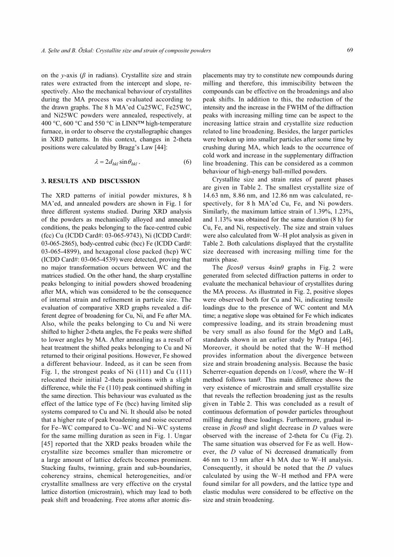
3. RESULTS AND DISCUSSION The XRD patterns of initial powder mixtures, 8 h MA’ed, and annealed powders are shown in Fig. 1 for three different systems studied. During XRD analysis of the powders as mechanically alloyed and annealed conditions, the peaks belonging to the face-centred cubic (fcc) Cu (ICDD Card#: 03-065-9743), Ni (ICDD Card#: 03-065-2865), body-centred cubic (bcc) Fe (ICDD Card#: 03-065-4899), and hexagonal close packed (hcp) WC (ICDD Card#: 03-065-4539) were detected, proving that no major transformation occurs between WC and the matrices studied. On the other hand, the sharp crystalline peaks belonging to initial powders showed broadening after MA, which was considered to be the consequence of internal strain and refinement in particle size. The evaluation of comparative XRD graphs revealed a dif-ferent degree of broadening for Cu, Ni, and Fe after MA. Also, while the peaks belonging to Cu and Ni were shifted to higher 2-theta angles, the Fe peaks were shifted to lower angles by MA. After annealing as a result of heat treatment the shifted peaks belonging to Cu and Ni returned to their original positions. However, Fe showed a different behaviour. Indeed, as it can be seen from Fig. 1, the strongest peaks of Ni (111) and Cu (111) relocated their initial 2-theta positions with a slight difference, while the Fe (110) peak continued shifting in the same direction. This behaviour was evaluated as the effect of the lattice type of Fe (bcc) having limited slip systems compared to Cu and Ni. It should also be noted that a higher rate of peak broadening and noise occurred for Fe–WC compared to Cu–WC and Ni–WC systems for the same milling duration as seen in Fig. 1. Ungar [45] reported that the XRD peaks broaden while the crystallite size becomes smaller than micrometre or a large amount of lattice defects becomes prominent. Stacking faults, twinning, grain and sub-boundaries, coherency strains, chemical heterogeneities, and/or crystallite smallness are very effective on the crystal lattice distortion (microstrain), which may lead to both peak shift and broadening. Free atoms after atomic dis-
placements may try to constitute new compounds during milling and therefore, this immiscibility between the compounds can be effective on the broadenings and also peak shifts. In addition to this, the reduction of the intensity and the increase in the FWHM of the diffraction peaks with increasing milling time can be aspect to the increasing lattice strain and crystallite size reduction related to line broadening. Besides, the larger particles were broken up into smaller particles after some time by crushing during MA, which leads to the occurrence of cold work and increase in the supplementary diffraction line broadening. This can be considered as a common behaviour of high-energy ball-milled powders.
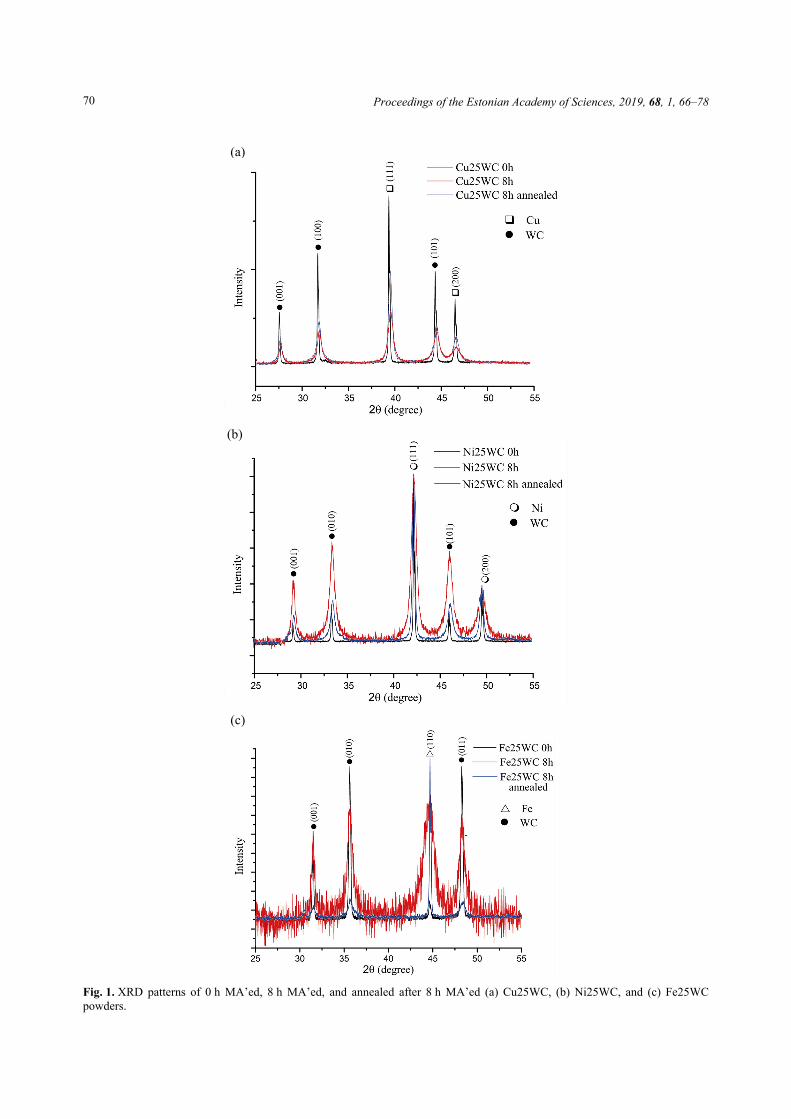
Crystallite size and strain rates of parent phases are given in Table 2. The smallest crystallite size of 14.63 nm, 8.86 nm, and 12.86 nm was calculated, re-spectively, for 8 h MA’ed Cu, Fe, and Ni powders. Similarly, the maximum lattice strain of 1.39%, 1.23%, and 1.13% was obtained for the same duration (8 h) for Cu, Fe, and Ni, respectively. The size and strain values were also calculated from W–H plot analysis as given in Table 2. Both calculations displayed that the crystallite size decreased with increasing milling time for the matrix phase.
The βcosθ versus 4sinθ graphs in Fig. 2 were generated from selected diffraction patterns in order to evaluate the mechanical behaviour of crystallites during the MA process. As illustrated in Fig. 2, positive slopes were observed both for Cu and Ni, indicating tensile loadings due to the presence of WC content and MA time; a negative slope was obtained for Fe which indicates compressive loading, and its strain broadening must be very small as also found for the MgO and LaB6 standards shown in an earlier study by Pratapa [46]. Moreover, it should be noted that the W–H method provides information about the divergence between size and strain broadening analysis. Because the basic Scherrer-equation depends on 1/cosθ, where the W–H method follows tanθ. This main difference shows the very existence of microstrain and small crystallite size that reveals the reflection broadening just as the results given in Table 2. This was concluded as a result of continuous deformation of powder particles throughout milling during these loadings. Furthermore, gradual in-crease in βcosθ and slight decrease in D values were observed with the increase of 2-theta for Cu (Fig. 2). The same situation was observed for Fe as well. How-ever, the D value of Ni decreased dramatically from 46 nm to 13 nm after 4 h MA due to W–H analysis. Consequently, it should be noted that the D values calculated by using the W–H method and FPA were found similar for all powders, and the lattice type and elastic modulus were considered to be effective on the size and strain broadening.
Proceedings of the Estonian Academy of Sciences, 2019, 68, 1, 66–78
70
(a)
(b)
(c)
Fig. 1. XRD patterns of 0 h MA’ed, 8 h MA’ed, and annealed after 8 h MA’ed (a) Cu25WC, (b) Ni25WC, and (c) Fe25WCpowders.
A. Şelte and B. Özkal: Crystallite size and strain of composite powders
71
Among all composite powders, the minimum crystallite size was detected in 8 h MA’ed powders. Marques et al. [4] reported that Cu crystallite size reaches a stable value below 30 nm in the presence of 20 wt% WC only after 32 h of milling in a planetary ball mill that was operated at a rotating speed of 400 rpm. A similar trend was observed in the study by Yusoff et al. [9], where Cu–W–C were mechanically alloyed in order to fabricate ex-situ composite powder with the final composition of Cu-30 vol% WC (approx. 42.7 wt% WC). Cu crystallite size became less than 30 nm only after 60 h milling in a planetary ball mill at 400 rpm rotary speed. Kumar et al. [47] reported that Fe crystallite size reaches around 12 nm after 20 h of MA by the addition of Cr and Al at 250 rpm rotary speed. The interesting study of Tung et al. [48] revealed that Fe nanoparticles can be fabricated by high-energy ball milling at a speed of 450 rpm and the crystallite size of 10 nm can be obtained after 16 h. In the presence of MnO, the Fe crystallite size below 30 nm was obtained after 20 h milling [49]. For Ni, Rane et al. [50] achieved Ni crystallite size between 15 and 29 nm after 80 h milling in a planetary ball and below 10 nm after 30 h milling in a shaker mill in the presence of 15% W. The average crystallite size of Ni, 58 nm, was obtained by milling in a planetary ball with the mechanical coating method [51]. Ni was also mechanically alloyed with Ti and its crystallite size reached below 40 nm only after 50 h of MA whereas the rotating speed was 300 rpm [52]. How-ever, in our study for Cu and Fe the crystallite size below 30 nm was reached after 2 h MA using a Spex high-energy ball mill at a speed of 1200 rpm by direct addition of 25 wt% WC, while it took 4 h for Ni (Table 2). It is expected that the deformation behaviour of Cu is different from that of Fe or Ni based on their hardness differences.
The crystallite size of Ni could reach below 30 nm only after 4 h. On the other hand, the lowest crystallite size was obtained for bcc Fe. These findings were considered to be the nature of crystal structure and strongly correlated with the elastic modulus. In the case of a higher elastic modulus, the crystallite size reduction upon MA may not be only due to plastic deformation and dislocation motions, but possible subgrain formations could also play an active role on the size refinement. The strain rates inversely correlated to crystallite size as expected, and maximum internal strain was obtained after 8 h MA.
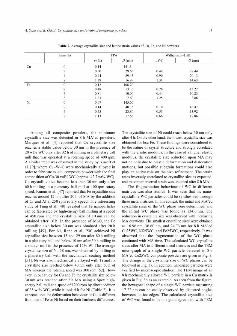
The fragmentation behaviour of WC in different matrices was also studied. It was seen that the nano-crystalline WC particles could be synthesized through these metal matrices. In this context, the initial and MA’ed crystallite sizes of the WC phase were determined, and the initial WC phase was found as 134.6 nm. The reduction in crystallite size was observed with increasing MA durations. The smallest crystallite sizes were obtained as 16.96 nm, 36.60 nm, and 24.73 nm for 8 h MA’ed Cu25WC, Ni25WC, and Fe25WC, respectively. It was observed that the fragmentation of the WC phase continued with MA time. The calculated WC crystallite sizes after MA in different metal matrices and the TEM micrograph of a single WC particle detected in 8 h MA’ed Cu25WC composite powders are given in Fig. 3. The change in the crystallite size of WC phases can be followed in Fig. 3a. In addition, nanosized particles were verified by microscopic studies. The TEM image of an 8 h mechanically alloyed WC particle in a Cu matrix is given in Fig. 3b as an example. As seen from the figure, the hexagonal shape of a single WC particle measuring 17.22 nm can be easily observed by distorted angles between lattice edges. The calculated crystallite size of WC was found to be in a good agreement with TEM
Table 2. Average crystallite size and lattice strain values of Cu, Fe, and Ni powders
Time (h) FPA Williamson–Hall
ε (%) D (nm) ε (%) D (nm)
0 0.14 141.3 2 0.50 29.63 0.49 22.44 4 0.94 29.43 0.90 20.13
Cu
8 1.39 16.99 1.31 14.63 0 0.12 108.20 2 0.48 13.35 0.26 13.22 4 0.81 10.00 0.44 10.23
Fe
8 1.23 7.60 1.25 8.86 0 0.07 145.60 2 0.14 40.35 0.10 46.47 4 0.55 23.80 0.53 13.92
Ni
8 1.13 17.65 0.66 12.86

Proceedings of the Estonian Academy of Sciences, 2019, 68, 1, 66–78
72
(a)
(b)
(c)
Fig. 2. Williamson–Hall plot analysis of (a) Cu25WC, (b) Ni25WC, and (c) Fe25WC composite powders MA’ed for 2 h, 4 h, and8 h, respectively.
A. Şelte and B. Özkal: Crystallite size and strain of composite powders
73
results. The XRD profile analysis in Bonache et al. [53] revealed a WC phase refined to a crystallite size of 19 nm after 100 h milling in a the planetary ball mill. The research by da Silva et al. [54] showed that the crystallite size of WC reaches below 40 nm after 10 h cryogenic ball milling. Besides, Back et al. [55] reported that Co addition decreases the crystallite size of WC particles under 30 nm for the same duration. However, our study showed that the WC crystallite size under 20 nm could be obtained for shorter milling durations in the presence of a high rate of ductile matrix. Consequently, one can say that XRD results confirm that our milling process has the advantage of the possibility of synthesizing fine-structured particles for shorter MA durations. It should also be noted that milling conditions are strongly correlated to obtain small crystallite sizes.
The calculated values of the lattice parameter and 2-theta position variations for initial and 2, 4, and 8 h MA’ed powders are given in Fig. 4. It is evident from Fig. 4 that the lattice parameter value of the Cu phase, aCu, predicted by the FPA, first decreased with milling time but then increased linearly with MA time. The Ni phase displayed a similar trend at the beginning of MA, but afterwards aNi decreased continuously with MA time. In contrast, aFe decreased slightly with MA time. It was thought that Cu and Ni crystals were under high tensile loadings in the presence of WC during MA, which can be seen as a remarkable change in the lattice parameter during milling. Despite the intense compressive loadings
to Fe crystals due to W–H analysis, a minor change occurred in the lattice parameter of Fe which was concluded to be a result of limited slip systems owing to its lattice type. This was observed as noise in XRD patterns and shifting in 2-theta positions. The 2-theta positions of Cu (111) and Ni (111) planes first increased, while Fe (110) first decreased by milling. With continuous milling the Fe (110) peak shifted towards lower angles while the Cu (111) and Ni (111) peaks shifted towards higher angles from their initial positions. However, Ni (111) planes shifted alternately with MA time. The peaks in a typical theta-2-theta scansion are expected to shift to lower angles in the case of compressive stress and to higher angles in the case of tensile stress due to high strain [56]. In our study, these observations were found to be in a good agreement with W–H analysis. These peak shifts were also considered to be exclusively caused by macroscopic stress called Type I strain, where the elastic strain and stress level of a crystallite is deter-mined by Hooke equations with considering the boundary conditions [56]. The other strains, of Type II and Type III, which are sub-microscopic quantity of Type I, contribute only to line broadening related to strain and size broadening [56], whose calculated values are given in Table 2. Scardi [57] stated that these strains are mostly regulated by elastic and plastic deformations, phase transformations, and mismatch of d-spacing in materials. In our study it was seen as well that MA caused a reduction of crystallite sizes, and this probably occurs
(a) (b)
Fig. 3. (a) Calculated WC crystallite sizes after mechanical alloying in different metal matrices and (b) TEM micrograph ofa single WC particle detected in 8 h MA’ed Cu25WC composite powder.
MA time (h)
Cry
stal
lite
siz
e (n
m)

Proceedings of the Estonian Academy of Sciences, 2019, 68, 1, 66–78
74
by strong plastic deformation with a dramatic change in the shape of particles. According to [58], the high rate of deformation, crystallite size, stoichiometry fluctuations (hexagonal phase particularly), and also (hkl) indices, which were calculated by software and the W–H method and are in good agreement, may be a reason for line broadening. However, Prabhu et al. [59] reported that the crystallite size and lattice strain are strongly effective on the Bragg peak.
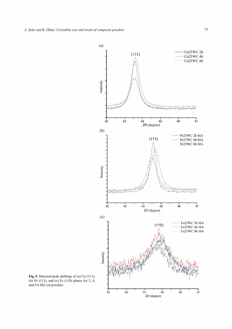
The width and intensity of the peak increase with the change in crystallite size and lattice strain, apparently leading to shifting. The shiftings for the strongest peaks belonging to Cu, Ni, and Fe are given in Fig. 5 for increasing MA time. The results are in a similar trend with Fig. 1 and Fig. 2. It should also be noted that shifting to higher angles is regulated by changing the (average) lattice parameter as shown in Fig. 3 as well as in [59].
(a)
(b)
Fig. 4. (a) Lattice parameter and (b) shift of position variations for initial and 2, 4, and 8 h MA’ed powders.
A. Şelte and B. Özkal: Crystallite size and strain of composite powders
75
(a)
(b)
(c)
Fig. 5. Detected peak shiftings of (a) Cu (111),(b) Ni (111), and (c) Fe (110) planes for 2, 4,and 8 h MA’ed powders.
Proceedings of the Estonian Academy of Sciences, 2019, 68, 1, 66–78
76
4. CONCLUSIONS In the present work, microstructural characterization of Cu–WC, Fe–WC, and Ni–WC nanostructured composite powders via MA was studied. The effects of milling time and the type of lattice as the surrounding ductile matrix (Cu, Fe, and Ni) during the fragmentation of the WC hard phase were investigated. Based on the obtained results, the following conclusions were drawn: 1. Peaks of Cu (111) and Ni (111) shifted to higher
angles by milling, while Fe (110) shifted to lower angles. On the other hand, Cu (111) and Fe (110) con-tinued shifting in the same direction with continuous milling. Besides, after annealing, the strongest peaks of Ni (111) and Cu (111) relocated to their initial 2-theta positions with a slight difference. However, the Fe (110) peak continued further shifting in the same direction.
2. A similar broadening behaviour was observed in all cases against increasing MA time. However, the crystallite size of matrices decreased and became saturated after 2 h. After 2 h, the crystallite size of matrices changed slightly with MA time. On the other hand, the crystallite size of WC in different matrices decreased with MA time. The fragmentation of the WC phase continues with MA time.
3. The Williamson–Hall plot method and FPA calculations were used in the analyses of the XRD peaks of phases by applying the Lorentzian profile, and the results were found to be in good agreement. With increasing MA durations, crystallite sizes decreased and strain values increased. The minimum crystallite size and maximum internal strain rates were estimated for 8 h MA’ed Cu25WC, Fe25WC, and Ni25WC composite powders as 14.63 nm and 1.39%, 7.60 nm and 1.23%, and 17.65 nm and 1.13%, respectively.
4. The crystallite sizes of Cu and Fe reach below 30 nm only after 2 h MA by direct addition of WC powders, whereas Ni reaches that value after 4 h MA. The smallest crystallite size of WC was calculated as 16.96 nm for the Cu matrix. A single nano-hexagonal WC particle was found during TEM investigations, and the observations were in good agreement with XRD calculations.
ACKNOWLEDGEMENTS The authors would like to thank Istanbul Technical University Research Fund (ITU-BAP) under Project No. 39304 for the financial support of this study. The publication costs of this article were partially covered by the Estonian Academy of Sciences.
REFERENCES
1. Llorca-Isern, N. and Artieda-Guzmán, C. Metal-based composite powders. In Advances in Powder Metallurgy (Chang, I. and Zhao, Y., ed.). Woodhead Publishing, Cambridge, 2013, 241–272.
2. Ajayan, P. M., Schadler, L. S., and Braun, P. V. Nano-composite Science and Technology. 1st ed. Wiley-VCH, Weinheim, 2003.
3. Park, S. J., Cowan, K., Johnson, J. L., and German, R. M. Grain size measurement methods and models for nanograined WC–Co. Int. J. Refract. Met. Hard Mater., 2008, 26, 152–163.
4. Marques, M. T., Livramento, V., Correia, J. B., Almeida, A., and Vilar, R. Study of early stages of Cu–NbC nano-composite synthesis. J. Alloys Compd., 2007, 434–435, 481–484.
5. Marques, M. T., Ferraria, A. M., Correia, J. B., Botelho do Rego, A. M., and Vilar, R. XRD, XPS and SEM characterisation of Cu–NbC nanocomposite produced by mechanical alloying. Mater. Chem. Phys., 2008, 109, 174–180.
6. Correia, J. B. and Marques, M. T. Production of a copper-iron carbide nanocomposite via mechanical alloying. Mater. Sci. Forum, 2004, 455, 501–504.
7. Dong, S. J., Zhou, Y., Chang, B. H., and Shi, Y. W. Formation of a TiB2-reinforced copper-based composite by mechanical alloying and hot pressing. Metall. Mater. Trans. A, 2002, 33, 1275–1280.
8. Shen, B. L., Itoi, T., Yamasaki, T., and Ogino, Y. Indentation creep of nanocrystalline Cu-TiC alloys prepared by mechanical alloying. Scripta Mater., 2000, 42, 893–898.
9. Yusoff, M., Othman, R., and Hussain, Z. Mechanical alloying and sintering of nanostructured tungsten carbide-reinforced copper composite and its charac-terization. Mater. Des., 2011, 32, 3293–3298.
10. Şelte, A. and Özkal, B. Infiltration behavior of mechanical alloyed 75 wt% Cu-25 wt% WC powders into porous WC compacts. Arch. Metall. Mater., 2015, 60. 1565–1568.
11. Deshpande, P. K. and Lin, R. Y. Wear resistance of WC particle reinforced copper matrix composites and the effect of porosity. Mater. Sci. Eng. A, 2006, 418, 137–145.
12. Takahashi, T. and Hashimoto, Y. Preparation of dispersion-strengthened coppers with NbC and TaC by mechanical alloying. Mater. Tran.s JIM, 1991, 32, 389–397.
13. Ying, D. Y. and Zhang, D. L. Processing of Cu–Al2O3 metal matrix nanocomposite materials by using high energy ball milling. Mater. Sci. Eng. A, 2000, 286, 152–156.
14. Naser, J., Riehemann, W., and Ferkel, H. Dispersion hardening of metals by nanoscaled ceramic powders. Mater. Sci. Eng. A, 1997, 234, 467–469.
15. Prosviryakov, A. S. SiC content effect on the properties of Cu–SiC composites produced by mechanical alloying. J. Alloys Compd., 2015, 632, 707–710.
16. Groza, J. R. and Gibeling, J. C. Principles of particle selection for dispersion-strengthened copper. Mater. Sci. Eng. A, 1993, 171, 115–125.
A. Şelte and B. Özkal: Crystallite size and strain of composite powders
77
17. Zhuo, H., Tang, J., and Ye, N. A novel approach for strengthening Cu–Y2O3 composites by in situ reaction at liquidus temperature. Mater. Sci. Eng. A, 2013, 584, 1–6.
18. Ružić, J., Stašić, J., Marković, S., Raić, K., and Božić, D. Synthesis and characterization of Cu-ZrB2 alloy produced by PM techniques. Sci. Sinter., 2014, 46, 217–224.
19. Xing, H. W., Cao, X. M., Hu, W. P., Zhao, L. Z., and Zhang, J. S. Interfacial reactions in 3D SiC network reinforced Cu matrix composites prepared by squeeze casting. Mater. Lett., 2005, 59, 1563–1566.
20. Vyas, T. K. and Pandey, A. A review on investigation of copper matrix composite by using stir casting method. Indian J. Appl. Res., 2015, 5, 75–77.
21. Gupta, M., Mohamed, F., and Lavernia, E. The effect of ceramic reinforcements during spray atomization and Co deposition of metal matrix composites part i: heat transfer. Metall. Trans. A, 1992, 23, 831–843.
22. Pagounis, E. and Lindroos, V. K. Processing and properties of particulate reinforced steel matrix composites. Mater. Sci. Eng. A, 1998, 246, 221–234.
23. Razavi, M., Rahimipour, M. R., Ebadzadeh, T., and Tousi, S. S. R. Synthesis of Fe–TiC nanocomposite from ilmenite concentrate via microwave heating. Bull. Mater. Sci., 2009, 32, 155–160.
24. Niu, L., Hojamberdiev, M., and Xu, Y. Preparation of in situ-formed WC/Fe composite on gray cast iron substrate by a centrifugal casting process. J. Mater. Process. Technol., 2010, 210, 1986–1990.
25. Wang, Y., Zhang, X., Zeng, G., and Li, F. In situ production of Fe–VC and Fe–TiC surface composites by cast-sintering. Composites Part A, 2001, 32, 281–286.
26. Das, K., Bandyopadhyay, T. K., and Das, S. A review on the various synthesis routes of TiC reinforced ferrous based composites. J. Mater. Sci., 2002, 37, 3881–3892.
27. Xi, W., Peng, R. L., Wu, W., Li, N., Wang, S., and Johansson, S. Al2O3 nanoparticle reinforced Fe-based alloys synthesized by thermite reaction. J. Mater. Sci., 2012, 47, 3585–3591.
28. Karak, S. K., Majumdar, J. D., Witczak, Z., Lojkowski, W., Ciupinski, L., Kurzydłowski, K. J., and Manna, I. Evaluation of microstructure and mechanical properties of nano-Y2O3-dispersed ferritic alloy synthesized by mechanical alloying and consolidated by high-pressure sintering. Metall. Mater. Trans. A, 2013, 44, 2884–2894.
29. Fernandes, F., Ramalho, A., Loureiro, A., Guilemany, J. M., Torrell, M., and Cavaleiro, A. Influence of nano-structured ZrO2 additions on the wear resistance of Ni-based alloy coatings deposited by APS process. Wear, 2013, 303, 591–601.
30. Suryanarayana, C., Klassen, T., and Ivanov, E. Synthesis of nanocomposites and amorphous alloys by mechanical alloying. J. Mater. Sci., 2011, 46, 6301–6315.
31. Turunen, E., Varis, T., Gustafsson, T. E., Keskinen, J., Falt, T., and Hannula, S. P. Parameter optimization of HVOF sprayed nanostructured alumina and alumina–nickel composite coatings. Surf. Coat. Technol., 2006, 200, 4987–4994,
32. Fu, C., Chan, S. H., Liu, Q., Ge, X., and Pasciak, G. Fabrication and evaluation of Ni-GDC composite
anode prepared by aqueous-based tape casting method for low-temperature solid oxide fuel cell. Int. J. Hydrogen Energ., 2010, 35, 301–307.
33. Wang, H., Xia, W., and Jin, Y. A study on abrasive resistance of Ni-based coatings with a WC hard phase. Wear, 1996, 195, 47–52.
34. St-Georges, L. Development and characterization of composite Ni-Cr plus WC laser cladding. Wear, 2007, 263, 562–566.
35. Lou, D., Hellman, J., Luhulima, D., Liimatainen, J., and Lindroos, V. K. Interactions between tungsten carbide (WC) particulates and metal matrix in WC-reinforced composites. Mater. Sci. Eng. A, 2003, 340, 155–162.
36. Gassmann, R., Nowotny, S., Luft, A., and Reitzenstein, W. Laser cladding of hard particles rich alloys. In Proceedings of International Congress on Applications of Lasers and Electro-Optics (Farson, D., Steen, W., and Miyamoto, I., eds). Laser Institute of America, Orlando, 1992, 288.
37. Surender, M., Balasubramanian, R., and Basu, B. Electro-chemical behaviour of electrodeposited Ni–WC composite coatings. Surf. Coat. Tech., 2004, 187, 93.
38. Dalfard, V. M. Effect of particle size of tungsten carbide on weight percent of carbide in Ni-WC nano-composite. Int. J. Electrochem. Sci., 2012, 7, 3537–3542.
39. Genç, A., Ayas, E., Öveçoğlu, M. L., and Turan, S. Fabrication of in situ Ni(W)–WC nano composites via mechanical alloying and spark plasma sintering. J. Alloys Compd., 2012, 542, 97–104.
40. Gu, D., Zhang, G., Dai, D., Wang, H., and Shen, Y. Nanocrystalline tungsten–nickel heavy alloy reinforced by in-situ tungsten carbide: mechanical alloying preparation and microstructural evolution. Int. J. Refract. Met. Hard Mater., 2013, 37, 45–51.
41. Fang, Z. Z., Wang, X., Ryu, T., Hwang, K. S., and Sohn, H. Y. Synthesis, sintering, and mechanical properties of nanocrystalline cemented tungsten carbide – a review. Int. J. Refract. Met. Hard Mater., 2009, 27, 288–299.
42. Suryanarayana, C. and Norton, M. G. X-ray Diffraction: a Practical Approach. Plenum Press, New York, 1998.
43. Williamson, G. K. and Hall, W. H. X-ray line broadening from filed aluminum and wolfram. Acta Metall., 1953, 1, 22–31.
44. Bragg, W. H. and Bragg, W. L. The reflexion of X-rays by crystals. Proc. R. Soc. Lond. A, 1913, 88, 428–438.
45. Ungar, T. Microstructural parameters from X-ray diffraction peak broadening. Scripta Mater., 2004, 51, 777–781.
46. Pratapa, S. and O’Connor, B. H. Development of MgO ceramic standards for X-ray and neutron line broadening assessments. Adv. X-ray Anal., 2002, 45, 41.
47. Kumar, R., Joardar, J., Raman, R. K. S., Raja, V. S., Joshi, S. V., and Parida, S. Effect of chromium and aluminium addition on anisotropic and microstructural characteristics of ball milled nanocrystalline iron. J. Alloys Compd., 2016, 671, 164–169.
48. Tung, D. K., Manh, D. H., Phong, L. T. H., Nam, P. H., Nam, D. N. H., Anh, N. T. N., Nong, H. T. T., Phan, M. H., and Phuc, N. X. Iron nanoparticles fabricated by high-energy ball milling for magnetic hyperthermia. J. Electron Mater., 2016, 45, 2644–2650.
Proceedings of the Estonian Academy of Sciences, 2019, 68, 1, 66–78
78
49. Pati, S. P. and Das, D. Interfacial magnetic phenomena of mechanosynthesized Fe nanoparticles in MnO matrix. Ceram. Int., 2014, 40, 10343–10349.
50. Rane, G. K., Apel, D., Welzel, U., and Mittemeijer, E. J. The microstructural evolution and thermal stability of nanocrystalline ball-milled Ni–15 at.% W powder. J. Mater. Res., 2013, 28, 873–886.
51. Yazdani, A. and Zakeri, A. An insight into formation of nanostructured coatings on metallic substrates by planetary ball milling. Powder Technol., 2015, 278, 196–203.
52. Sharma, N., Raj, T., and Jangra, K. K. Microstructural evaluation of NiTi-powder, steatite, and steel balls after different milling conditions. Mater. Manuf. Process., 2016, 31, 628–632.
53. Bonache, V., Salvador, M. D., Busquets, D., and Segovia, E. F. Fabrication of ultrafine and nanocrystalline WC–Co mixtures by planetary milling and subsequent consolidations. Powder Metall., 2011, 54, 214–221.
54. Da Silva, F. T., Nunes, M. A. M, de Oliveira, R. M. V., da Silva, G. G., de Souza, C. P., and Gomes, U. U. Analysis of crystallite size and microdeformation crystal lattice the tungsten carbide milling in mill high
energy. In 19 CBECIMAT: Proceedings of Brazilian Congress on Engineering and Materials Science. Trans Tech Publications, Brazil, 2010, 527.
55. Back, S. H., Lee, G. H., and Kang, S. Effect of cryomilling on particle size and microstrain in a WC-Co alloy. Mater. Trans., 2005, 46, 105–110.
56. Popa, N. C. Microstructural properties: texture and macrostress effects. In Powder Diffraction (Dinnebier, R. E. and Billinge, S. J. L., eds). RCS Publishing, Cambridge, 2008, 332–375.
57. Scardi, P. Microstructural properties: lattice defects and domain size effects. In Powder Diffraction (Dinnebier, R. E. and Billinge, S. J. L., eds). RCS Publishing, Cambridge, 2008, 376–413.
58. Leineweber, A. and Mittemeijer, E. J. Diffraction line broadening due to lattice-parameter variations caused by a spatially varying scalar variable: its orientation dependence caused by locally varying nitrogen content in ε-FeN0.433. J. Appl. Crystallogr., 2004, 37, 123–135.
59. Prabhu, Y. T., Rao, K. V., Kumar, V. S. S., and Kumari, B. S. X-ray analysis by Williamson-Hall and size-strain plot methods of ZnO nanoparticles with fuel variation. World J. Nano Sci. Eng., 2014, 4, 21–28.
Mehaanilise legeerimise teel sünteesitud kõvade osakestega tugevdatud komposiitpulbrite (Cu/Ni/Fe–WC) kristalliidi suuruse ja deformatsioonide arvutused
Aydın Şelte ja Burak Özkal
Uuriti muutusi kristalliidi suuruses (D) ja võre deformatsiooniastmes (ε) mehaanilise legeerimise (MA) teel valmis-tatud WC osakestega tugevdatud Cu, Fe ning Ni komposiidi pulbritel. Maatriksfaaside ε ja D väärtuste hindamiseks XRD tulemustes kasutati Lorentzi funktsiooni koos Williamsoni-Halli (W-H) analüüsiga ning põhiparameetrite lähe-nemist (FPA). Kasvava MA ajaga kaasnes maatriksfaaside ε väärtuste suurenemine, samas kui D väärtused näitasid vähenemist. Lisaks sellele muutusid võre parameetrid aCu ja aNi aja jooksul lineaarselt ning aFe näitas väikest langust. Cu (111) tasapinnale kuuluv XRD piik on nihutatud suurema 2-teeta nurga suunas. Vastupidiselt vasele nihkus Fe (110) piik MA ajaga madalamatele nurkadele. XRD piik, mis kuulub Ni (111) tasapinnale, näitas vahelduvat suunda. Sarnased tulemused saadi nii W-H analüüsist kui ka FPA arvutustest. Minimaalne kristalliidi suurus ja maksimaalne deformatsiooniaste oli hinnanguliselt 8 tundi jahvatatud Cu25WC, Fe25WC ja Ni25WC komposiitpulbritel vastavalt 14,63 nm ja 1,39%, 7,60 nm ja 1,23% ning 17,65 nm ja 1,13%. Transmissioon-elektronmikroskoobi (TEM) vaatluste käigus leiti XRD arvutuste kristalliidi suurusega hea kooskõla.