Cpj REG 0 '~.N/Ur REGULATORY GUI - nrc.gov · cpj reg u 0 '~.n/ur 065.'t u.s. nuclear regulatory...
21
Cpj REG U 0 '~.N/Ur 0 65.'t U.S. NUCLEAR REGULATORY COMMISSION REGULATORY GUI OFFICE OF STANDARDS DEVELOPMENT April 1977 LI REGULATORY GUIDE 3.33 1 ASSUMPTIONS USED FOR EVALUATING THE POTENTIAL RADIOLOGICAL CONSEQUENCES OF ACCIDENTAL NUCLEAR CRITICALITY IN A FUEL REPROCESSING PLANT A. INTRODUCTION Section 50.34, "Contents of Applications: Technical Information," of 10 CFR Part 50, "Licens- safety research programs. This guide lists assump- tions used to evaluate the magnitude and radiological consequences of a criticality accident in a fuel reprocessing plant. ing of Production and Utilization Facilities," re- quires that each applicant for a construction permit A criticality accident is an acci esulting in the or operating license provide an analysis and evalua- uncontrolled release of energy o a semblage of tion of the design and performance of structures, fissile material. The circu sta of a ticality ac- systems, and components of the facility with the ob- cident are difficult to wever, the most jective of assessing the risk to public health and safety serious criticality ac nt expected to oc- resulting from operation of the facility and including cur when the reac ty h tent of the deviation determination of the adequacy of structures, systems, from criticalit f ea c ain reacting medium) and components provided for the prevention of acci- could increas st and without control in dents and the mitigation of the consequences of acci- the fissi c 'on f largest credible mass. In a dents. fuel re p t where conditions that might le c a re carefully avoided because of the In a fuel reprocessing plant, a criticality accident is po• l adverse physical and radiological ef- one of the postulated accidents used to evaluate the c an accident is extremely uncommon. adequacy of an applicant's proposed activities with e , experience with these and related facilities respect to the public health and safety. The m s monstrated that criticality accidents could oc- described in this guide result from review and tion c on a number of specific cases and, as su fl the latest general NRC-approved approac to the In a fuel reprocessing plant, such an accident might lem. If an applicant desires to e oy in- be initiated by (I) inadvertent transfer or leakage of a formation that may be developed in t or to solution of fissile material from a geometrically safe use an alternative method, NRC will iew the containing vessel into an area or vessel not so proposal and approve ntrke, if found acceptable. designed, (2) introduction of excess fissile material In the procg of ? w'w applications for permits and lice aLhoriz g the construction or opera- tion of elg plants, the NRC staff has develoP ppropritely conservative assumptions that are by the staff to evaluate an estimate of the radiolo cal consequences of various postulated accidents. These assumptions are based on previous accident experience, engineering judgment, and on the analysis of applicable experimental results from solution to a vessel, (3) introduction of excess fissile material to a solution, (4) overconcentration of a solution, (5) failure to maintain sufficient neutron ab- sorbing materials in a vessel, (6) precipitation of fis- sile solids from a solution and their retention in a ves- sel, (7) introduction of neutron moderators or reflec- tors (e.g., by addition of water to a highly under- moderated system), (8) deformation of or failure to maintain safe storage arrays, or (9) similar actions that can lead to increases in the reactivity of fissile systems. Some acceptable means for minimizing the likelihood of such accidents are described in USNRC REGULATORY GUIDES Comments should be sent to the Secretary of the Commission, US. Nuclear Regu- Regulatory Guides are issued to describe and make available to the public methods latory Commission, Washington, D.C. 20555, Attention: Docketing and Service acceptable to the NRC staff of implementing specific parts of the Commission's Branch. regulations, to delineate techniques used by the staff in evaluating specific problems The guides are issued in the following ten broad divisions or postulated accidents, or to provide guidance to applicants. Regulatory Guides are not substitutes for regulations, and compliance with them is not required. 1. Power Reactors 6. Products Methods and sol utions different from those set Out in the guides will be accept- 2. Research and Test Reactors 7. Transportation able if they provide a basis for the findings requisite to the issuance or continuance 3. Fuels and Materials Facilities 8. Occupational Health of a permit or license by the Commission. 4. Environmental and Siting 9. Antitrust Review 5. Materials and Plant Protection 10. General Comments and suggestions for improvements in these guides are encouraged at all times, and guides will be revised, as appropriate, to accommodate comments and Requests for single copies of issued guides (which may be reproduced) or for place- to reflect new information or experience. However, comments on this guide,if ment on an automatic distribution list for single copies of future guides in specific ieceived within about two months after its issuance, will be particularly useful in divisions should be made in writing to the US. Nuclear Regulatory Commission, evaluating the need for an early revision. Washington, D.C. 20555, Attention: Director. Division of Document Control.
Transcript of Cpj REG 0 '~.N/Ur REGULATORY GUI - nrc.gov · cpj reg u 0 '~.n/ur 065.'t u.s. nuclear regulatory...

Cpj REG U0
'~.N/Ur 065.'t
U.S. NUCLEAR REGULATORY COMMISSION
REGULATORY GUIOFFICE OF STANDARDS DEVELOPMENT
April 1977
LI
REGULATORY GUIDE 3.33 1
ASSUMPTIONS USED FOR EVALUATING THE POTENTIAL RADIOLOGICALCONSEQUENCES OF ACCIDENTAL NUCLEAR CRITICALITY IN A FUEL
REPROCESSING PLANT
A. INTRODUCTION
Section 50.34, "Contents of Applications:Technical Information," of 10 CFR Part 50, "Licens-
safety research programs. This guide lists assump-tions used to evaluate the magnitude and radiologicalconsequences of a criticality accident in a fuelreprocessing plant.
ing of Production and Utilization Facilities," re-quires that each applicant for a construction permit A criticality accident is an acci esulting in theor operating license provide an analysis and evalua- uncontrolled release of energy o a semblage oftion of the design and performance of structures, fissile material. The circu sta of a ticality ac-systems, and components of the facility with the ob- cident are difficult to wever, the mostjective of assessing the risk to public health and safety serious criticality ac nt expected to oc-resulting from operation of the facility and including cur when the reac ty h tent of the deviationdetermination of the adequacy of structures, systems, from criticalit f ea c ain reacting medium)and components provided for the prevention of acci- could increas st and without control indents and the mitigation of the consequences of acci- the fissi c 'on f largest credible mass. In adents. fuel re p t where conditions that might
le c a re carefully avoided because of theIn a fuel reprocessing plant, a criticality accident is po• l adverse physical and radiological ef-
one of the postulated accidents used to evaluate the c an accident is extremely uncommon.adequacy of an applicant's proposed activities with e , experience with these and related facilitiesrespect to the public health and safety. The m s monstrated that criticality accidents could oc-described in this guide result from review and tion con a number of specific cases and, as su fl thelatest general NRC-approved approac to the In a fuel reprocessing plant, such an accident mightlem. If an applicant desires to e oy in- be initiated by (I) inadvertent transfer or leakage of aformation that may be developed in t or to solution of fissile material from a geometrically safeuse an alternative method, NRC will iew the containing vessel into an area or vessel not soproposal and approve ntrke, if found acceptable. designed, (2) introduction of excess fissile material
In the procg of ? w'w applications for permitsand lice aLhoriz g the construction or opera-tion of elg plants, the NRC staff hasdeveloP ppropritely conservative assumptionsthat are by the staff to evaluate an estimate ofthe radiolo cal consequences of various postulatedaccidents. These assumptions are based on previousaccident experience, engineering judgment, and onthe analysis of applicable experimental results from
solution to a vessel, (3) introduction of excess fissilematerial to a solution, (4) overconcentration of asolution, (5) failure to maintain sufficient neutron ab-sorbing materials in a vessel, (6) precipitation of fis-sile solids from a solution and their retention in a ves-sel, (7) introduction of neutron moderators or reflec-tors (e.g., by addition of water to a highly under-moderated system), (8) deformation of or failure tomaintain safe storage arrays, or (9) similar actionsthat can lead to increases in the reactivity of fissilesystems. Some acceptable means for minimizing thelikelihood of such accidents are described in
USNRC REGULATORY GUIDES Comments should be sent to the Secretary of the Commission, US. Nuclear Regu-Regulatory Guides are issued to describe and make available to the public methods latory Commission, Washington, D.C. 20555, Attention: Docketing and Service
acceptable to the NRC staff of implementing specific parts of the Commission's Branch.
regulations, to delineate techniques used by the staff in evaluating specific problems The guides are issued in the following ten broad divisionsor postulated accidents, or to provide guidance to applicants. Regulatory Guidesare not substitutes for regulations, and compliance with them is not required. 1. Power Reactors 6. ProductsMethods and sol utions different from those set Out in the guides will be accept- 2. Research and Test Reactors 7. Transportationable if they provide a basis for the findings requisite to the issuance or continuance 3. Fuels and Materials Facilities 8. Occupational Health
of a permit or license by the Commission. 4. Environmental and Siting 9. Antitrust Review5. Materials and Plant Protection 10. General
Comments and suggestions for improvements in these guides are encouraged at alltimes, and guides will be revised, as appropriate, to accommodate comments and Requests for single copies of issued guides (which may be reproduced) or for place-to reflect new information or experience. However, comments on this guide,if ment on an automatic distribution list for single copies of future guides in specificieceived within about two months after its issuance, will be particularly useful in divisions should be made in writing to the US. Nuclear Regulatory Commission,evaluating the need for an early revision. Washington, D.C. 20555, Attention: Director. Division of Document Control.

Regulatory Guides 3.4, "Nuclear Criticality Safety inOperations with Fissionable Material Outside Reac-tors,"' and 3.1, "Use of Borosilicate Glass RaschigRings as a Neutron Absorber in Solutions of FissileMaterial."'
1. Criticality Accident Experience in Relation to theEstimation of the Most Severe Accident
Stratton (Ref. 1) has reviewed in detail 34 occa-sions prior to 1966 when the power level of a fissilesystem increased without control as a result of un-planned or unexpected changes in its reactivity.Although only six of these incidents occurred inprocessing operations, and the remainder occurredmostly in facilities for obtaining criticality data or inexperimental reactors, the information obtained andits correlation with the characteristics of each systemhave been of considerable value for use in estimatingthe consequences of accidental criticality in processsystems. The incidents occurred in aqueous solutionsof uranium or plutonium (10), in metallic uranium orplutonium in air (9), in inhomogeneous water-moderated systems (9), and in miscellaneous soliduranium systems (6).
The estimated total number of fissions per incidentranged from IE+15 2 to IE+20 with a median ofabout 2E+17. More recently another incident in aplutonium processing facility in Windscale (U.K.)was described in which a total yield of about IE+15fissions apparently occurred (Ref. 2). In ten cases, thesupercriticality was halted by an automatic controldevice. In the remainder, the shutdown was effectedas a consequence of the fission energy release thatresulted in thermal expansion, density reduction fromthe formation of very small bubbles, mixing of lightand dense layers, loss of water moderator by boiling,or expulsion of part of the mass.
Generally, the criticality incidents werecharacterized by an initial burst or spike in the curveof fission rate versus time followed by a rapid but in-complete decay as the shutoff mechanism was in-itiated. As more than one shutdown mechanism mayaffect the reactivity of the system and the effect of aparticular mechanism may be counteracted, the in-itial burst was frequently succeeded by a plateauperiod of varying length. This plateau wascharacterized by a lesser and declining fission rateand finally by a further dropoff as shuldown wascompleted. The magnitude of the initial burst wasdirectly related to the rate of increase of reactivityand its magnitude above the just-critical value but
' Copies may be obtained from tfie U.S. Nuclear RegulatoryCommission, Washington, D.C. 20555, Attention: Director, Divi-sion of Document Control.2 IE+ 15 = I x 10". This notational form will be used throughout
this guide.
was inversely related to the background neutron flux,which is much greater for plutonium than foruranium systems.
Those systems consisting only of solid fissile,reflector, or moderator materials exhibited little orno plateau period, whereas solution systems had welldeveloped plateaus. For solution systems, the energyrelease during the plateau period, because of its dura-tion, provided the major portion of the total energyreleased. For purposes of the planning necessary todeal adequately with criticality incidents in ex-perimental and production-type nuclear facilities,Woodcock (Ref. 3) made use of these data to estimatepossible fission yields from excursions in varioustypes of systems. For example, spike yields of IE+ 17and I E+ 18 and total yields of 3E+ 18 and 3E+ 19 fis-sions were suggested for criticality accidents occur-ring in solution systems of 100 gallons or less andmore than 100 gallons, respectively. Little or nomechanical damage was predicted at these levels.
2. Methods Developed for Predicting the Magnitude ofCriticality Accidents
The nuclear excursion behavior of solutions ofenriched uranium has been studied extensively boththeoretically and experimentally. A summary byDunenfeld and Stitt (Ref. 4) of the kinetic experi-ments on water boilers, using uranyl sulfate solu-tions, describes the development of a kinetic modelthat was confirmed by experiment. This modeldefines the effects of thermal expansion andradiolytic gas formation as power-limiting and shut-down mechanisms.
The results of a series of criticality excursion ex-periments resulting from the introduction of uranylnitrate solutions to vertical cylindrical tanks at vary-ing rates are summarized by Lecorch6 and Seale (Ref.5). This report confirms the applicability of thekinetics model for solutions, provides correlations ofpeak power with reactivity addition rate, notes theimportance of a strong neutron source in limitingpeak power, and indicates the nature of the plateaufollowing the peak.
Many operations with fissile materials in a fuelreprocessing plant are conducted with aqueous (ororganic solvent) solutions of fissile materials. Conse-quently, well-founded methods for the prediction oftotal fissions and maximum fission rate for accidentsthat might occur in solutions (in process or other ves-sels) by the addition of fissile materials should be ofconsiderable value in evaluating the effects of possi-ble reprocessing plant criticality accidents. From theresults of the excursion studies and from accidentdata, Tuck (Ref. 6) has developed methods for es-timating (1) the maximum number of fissions in a 5-second interval (the first spike), (2) the total numberof fissions, and (3) the maximum specific fission rate
ei
0
I3.33-2

in vertical cylindrical vessels, 28 to 152 cm indiameter and separated by > 30 cm from a bottomreflecting surface, resulting from the addition of up to500 g/l solutions of Pu-239 or U-235 to the vessel atrates of 0.1 to 7.5 gal/min. Tuck also gives a methodfor estimating the power level from which the steam-generated pressure may be calculated and indicatesthat use of the formulas for tanks >152 cm indiameter is possible with a loss in accuracy.
Methods for estimating the number of fissions inthe initial burst and the total number of fissions,derived from the work reported by Lcorchi andSeale (Ref. 5), have also been developed by Olsen andothers (Ref. 7). These were evaluated by applicationto ten actual accidents which have occurred in solu-tions and were shown to give conservative estimatesin all cases except one.
Fission yields for criticality accidents occurring insolution and some heterogeneous systems, e.g., li-quid/fixed geometry, can be reasonably estimated us-ing existing methods. However, methods for es-timating the possible fission yield from other types ofheterogeneous systems, e.g., liquid/powder, are lessreliable because of the uncertainties of predictingsystem reactivity rate. The uncertainties of geometryand moderation result in a broad range of possibleyields.
Woodcock (Ref. 3) estimated that in solidplutonium systems, solid uranium systems, andheterogeneous liquid/powder systems (fissilematerial not specified) total fission yields (substan-tially occurring within the spike) of IE+ 18, 3E+ 19,and 3E+20, respectively, could be predicted.Mechanical damage varied from slight to extensive.Heterogeneous systems consisting of metals or solidsin water were estimated to achieve a possiblemagnitude of IE+19 following an initial burst of3E+18 fissions. Operations in a fuel reprocessingplant involve only a small number of complete as-semblies of fuel rods, except in the fuel storage pool.In the latter area, a rigid array of assemblies is main-tained and normally only a single assembly may be inmotion in the vicinity of the array. Consequently, therate of reactivity addition in such a system would bequite low, and the predicted magnitude of a criticalityincident would be correspondingly low. These es-timates could aid in the analysis of situations in plantsystems. However, they should not be taken as ab-solute values for criticality assumptions for the pur-pose of this guide.
For systems other than solution systems, the es-timation of the peak fission rate and the total numberof fissions accompanying an accidental nuclearcriticality may be accomplished with the aid of infor-mation derived from accident experience, from ex-periments on reactors utilizing bare uranium metal
(Ref. 8), and from the SPERT-I reactor transienttests with light- and heavy-water moderateduranium-aluminum and U0 2-stainless steel fuels(Ref. 9). Oxide core tests in the latter group providesome information on energy release mechanisms thatmay be effective, for example, in spent fuel storage orfuel leaching systems in a reprocessing plant. Reviewof unusual reprocessing structures, systems, and com-ponents for the possibility of accidental criticalityshould also consider recognized anomalous situa-tions in which the possibility of accidental nuclearcriticality may be conceived (Ref. 10).
The application of the double-contingency prin-ciple3 to fissile material processing operations hasbeen successful in reducing the probability of ac-cidental criticality to a low value. As a consequence,the scenarios required to arrive at accidentalcriticality involve the assumption of multiplebreakdowns in the nuclear criticality safety controls.It has therefore been a practice to simply and conser-vatively assume an accidental criticality of amagnitude equal to, or some multiple of, thehistorical maximum for all criticality accidents out-side reactors without using any scenario clearlydefined by the specific operations being evaluated. Inthe absence of sufficient guidance, there has beenwide variation in the credibility of the postulatedmagnitude of the occurrence (particularly the size ofthe initial burst), the amount of energy and radioac-tivity assumed to be released, and the magnitude ofthe calculated consequences.
It is the staff's judgment that the evaluation of thecriticality accident should assume the simultaneousbreakdown of at least two independent controlsthroughout all elements of the operation. Each con-trol should be such that its circumvention is of verylow probability. Experience has shown that thesimultaneous failure of two independent controls isvery unlikely if the controls are derived, applied, andmaintained with a high level of quality assurance.However, if controls highly dependent on human ac-tions are involved, this approach will call for somevariation in the assumed number of control failures.The criticality accidents so conceived should then beanalyzed to determine the most severe within theframework of assumed control failures, using realisticvalues of such variables as the fissile inventory, vesselsizes, and pump transfer rates.
3. Radiological Consequences of AccidestalCriticality
Past practice has been to evaluate the radiologicalconsequences to individuals of postulated accidentalcriticality in fuel reprocessing plants in terms of a frac-3 The double-contingency principle is defined in ANSI N16-1-1969, "Nuclear Criticality Safety in Operations with FissionableMaterials Outside Reactors," which is endorsed by RegulatoryGuide 3.4.
3.33-3

tion of the guideline values in 10 CFR Part 100,"Reactor Site Criteria."
The consequences of a criticality accident may belimited by containment, shielding, isolation distance,or evacuation of adjacent occupied areas subsequentto detection of the accident. If the impact of a criticalityaccident is to be limited through evacuation of adja-cent occupied areas, there should be prior, formal ar-rangements with individual occupants and/or local authorities sufficient to ensure that suchmovements can be effected in the time allowed.
C. REGULATORY POSITION
1. Following are the plant assessment and assump-tions related to energy release from a criticality acci-dent and the minimum criticality accident to be con-sidered:
a. When defining the characteristics of an assumedcriticality accident in order to assess the adequacy ofstructures, systems, and components provided for themitigation of the consequences of accidents, the ap-plicant should evaluate credible criticality accidentsin all those elements of the plant provided for thestorage, handling, or processing of fissile materials orinto which fissile materials in significant amountscould be introduced. To determine the circumstancesof the criticality accidents, controls judged equivalentto at least two highly reliable, independent criticalitycontrols should be assumed to be circumvented. Themagnitude of the possible accidents should then beassessed, on an individual case basis, to estimate theextent and nature of possible effects and to providesource terms for dose calculations. The most severeaccident should then be selected for the assessment ofthe adequacy of the plant.
Calculation of the radioactivity of fission productsand transuranic elements initially present and laterproduced in the incident should be accomplished bycomputer codes ORIGEN (Ref. 11) and RIBD (Ref.12), respectively. An equivalent calculation may besubstituted, if justified on an individual case basis.
b. If the results of the preceding evaluation in-dicate that no possible criticality accident exceeds inseverity the criticality accident postulated in this sec-tion, then the conditions of the following examplemay be assumed for the purpose of assessing the ade-quacy of the facility. A less conservative set of condi-tions may be used if they are shown to be applicableby the specific analyses conducted in accordance withparagraph C.l.a above.
An excursion is assumed to occur in a vented vesselof unfavorable geometry containing a solution of 400g/l of uranium enriched to less than 5% U-235. Thesolution is also assumed to contain all of the trans-uranic elements and fission products, except the no-
ble gases, expected to be present in the spent fuel atthe maximum burnup and the minimum postirradia-tion decay time for which the plant is designed. Thesedata included in this guide (see Table 1) list theradioactivity of available significant nuclides assum-ing 100% dissolution, the burnup to be 33.000MWd/MTU, and a postirradiation decay time of 150days.
The vessel is assumed to be located within a ven-tilated cell which provides shielding equivalent to 5feet of concrete with a density of 142 lb/ft3. The ex-cursion produces an initial burst of 1 E+ 18 fissions in0.5 second followed successively at 10-minute inter-vals by 47 bursts of 1.9E+ 17 fissions for a total of1E+ 19 fissions in 8 hours. The excursion is assumedto be terminated by evaporation of 100 liters of asolution containing 400 g/l of uranium (<5%enriched) and concentrations of associated fissionproducts and transuranic elements corresponding tothe sum of those produced in the incident plus thosepresent in irradiated fuel (assuming 100% dissolution)for the plant design condition. However, the noblegas fission products initially present in the fuel are as-sumed to have been removed prior to the incident.Table 2 lists the radioactivity of significant nuclidesreleased from the criticality accident.
2. Assumptions related to the release of radioactivematerial are as follows:.
a. It should be assumed that all of the noble gasfission products (except those removed prior to theexcursion), 25% of the iodine radionuclides, and 0.1%of the ruthenium radionuclides resulting from the ex-cursion or initially present in the spent fuel arereleased directly to the cell atmosphere. It should alsobe assumed that an aerosol, which is generated fromthe evaporation of solution during the excursion, isreleased directly to the cell atmosphere. The aerosolshould be assumed to comprise 0.05% of the salt con-tent of the solution that is evaporated. The cellvolume and ventilation rate should be considered onan individual case basis.
b. The effects of radiological decay during transitin cell and in the plant exhaust system should betaken into account on an individual case basis.
c. The reduction in the amount of radioactivematerial available for release to the environmentthrough the plant stack(s) as a result of the normaloperation of sorption or filtration systems in theplant exhaust systems may be taken into account, butthe amount of reduction in the concentration ofradioactive materials should be evaluated on an in-dividual case basis.
' Certain assumptions for release of radioactive material, doseconversions, and atmospheric diffusion reflect the staff's positionindicated in Regulatory Guide 1.3 (Ref. 22).
a
I3.33-4
3. Acceptable assumptions for dose and dose conver-sion are as follows:
a. The applicant should show that the conse-quences of the prompt gamma and neutron dose aresufficiently mitigated to allow occupancy of areasnecessary to maintain the plant in a safe conditionfollowing the accident. The following semi-empiricalequations should be used for these calculations.These equations are acceptable to the NRC staff andwere developed from experimental data. Differentmethods may be substituted, if justified on an in-dividual case basis. Potential total dose attenuationdue to shielding and dose exposures should beevaluated on an individual case basis.
(1) Prompt' Gamma Dose
Dy = 2.1E-20N d2 e-3.4d
where
Dy = gamma dose (rem)
N = number of fissions
d = distance from source (km)
Data presented in The Effects of NuclearWeapons (Ref. 13, p. 384) should be used to developdose reduction factors. For concrete, the dose shouldbe reduced by a factor of 2.5 for the first 8 inches, afactor of 5.0 for the first foot, and a factor of 5.5 foreach additional foot.
(2) Prompt Neutron Dose
Dn = 7E- 20N d"2 e-1.2d
where
Dn = neutron dose (rem)
N = number of fissions
d = distance from source (km)
For concrete, the dose should be reduced by afactor of 2.3 for the first 8 inches, 4.6 for the firstfoot, and a factor of 20 for each additional foot.
b. No correction should be made for depletion ofthe effluent plume of radioactive iodine due todeposition on the ground or for the radiologicaldecay of iodine in transit.
c. For the first 8 hours, the breathing rate of aperson offsite should be assumed to be 3.47E-4m3/sec. Frorm 8 to 24 hours following the accident,the breathing rate should be assumed to be 1.75E-4I Most of the neutron and part of the gamma radiation are emittedin the actual fission process. Some gamma radiation is produced invarious secondary nuclear processes, including decay of fissionproducts. For the purposes of this guide, "prompt" gamma dosesshould be evaluated including the effects of decay of significant fis-sion products during the first minute of the excursion.
m3/sec. These values were developed from theaverage daily breathing rate (2E + 7 cm 3/day) as-sumed in the report of ICRP Committee 11-1959(Ref. 14).
d. External whole body doses should be calculatedusing "infinite cloud" assumptions, i.e., the dimen-sions of the cloud are assumed to be large comparedto the distance that the gamma rays and beta particlestravel. "Such a cloud would be considered an infinitecloud for a receptor at the center because any ad-ditional [gamma and] beta emitting material beyondthe cloud dimensions would not alter the flux of[gamma rays and] beta particles to the receptor."[See Meteorology and A tomic Energy-1968 (Ref. 15),Section 7.4.1.1; editorial additions made so that gam-ma and beta emitting material could be considered.]Under these conditions the rate of energy absorptionper unit volume is equal to the rate of energy releasedper unit volume. For an infinite uniform cloud con-taining x curies of beta radioactivity per cubic meter,the beta dose rate in air at the cloud center is
PDz0 0.457 Ep X
The surface body dose rate from beta emitters in theinfinite cloud can be approximated as being one-halfthis amount (i.e., 3D-• = 0.23 Ep3x). For gammaemitting material, the dose rate in air at the cloudcenter is
YD = 0.507 EyX
From a semi-infinite cloud, the gamma dose rate inair is
yD • = 0.25 EX
where
PD:ý = beta dose rate from an infinite cloud(rad/sec)
yDc- = gamma dose rate from an infinite cloud(rad/sec)
E13 = average beta energy per disintegration(MeV/dis)
= average gamma energy per disintegration(MeV/dis)
X = concentration of beta or gamma emittingisotope in the cloud (Ci/m 3)
e. The following specific assumptions are accep-table with respect to the radioactive cloud dosecalculations:
(1) The dose at any distance from the plantshould be calculated based on the maximum con-centration time integral (in the course of the accident)in the plume at that distance, taking into accountspecific meteorological, topographical, and other
3.33-5
characteristics that may affect the maximum plumeconcentration. These site-related characteristicsshould be evaluated on. an individual case basis. Inthe case of beta radiation, the receptor is assumed tobe exposed to an infinite cloud at the maximumground level concentration at that distance from theplant. In the case of gamma radiation, the receptor isassumed to be exposed to only one-half the cloud ow-ing to the presence of the ground. The maximumcloud concentration should always be assumed to beat ground level.
(2) The appropriate average beta and gammaenergies emitted per disintegration used should be asgiven in the Table of Isotopes (Ref. 16).
(3) The whole body dose should be consideredas the dose from gamma radiation at a depth of 5 cmand the genetic dose at a depth of I cm. The skin doseshould be the sum of the surface gamma dose and thebeta dose at a depth of 7 gm/cm2 . The beta skin dosemay be estimated by applying an energy dependentattenuation factor (Dd/DB) to the surface doseaccording to a method developed by Loevinger,Japha, and Brownell (Ref. 17). (See Figure 1.)
f. The "critical organ" dose from the inhaledradioactive materials should be estimated. The"critical organ" is that organ which receives thehighest radiation dose after the isotope is absorbedinto the body. For the purpose of this guide, the fol-lowing assumptions should be made:
(1) The radionuclide dose conversion factors areas recommended by the report of Committee I1,ICRP (Ref. 14).
(2) The effective half-life for the nuclide is asrecommended in ICRP Publication 6 (Ref. 18).
(3.) The plutonium and other actinide nuclideclearance half time, or fraction of nuclide clearing theorgan, is as recommended by the ICRP task group onlung dynamics (Ref. 19). A computer code,DACRIN, (Ref. 20) is available for this model. Taskgroup lung model (TGLM) clearance parameters arepresented in Table 3; the model is shown schematical-ly in Figure 2.
g. The potential dose for all significant nuclidesshould be estimated for the population distributionon a site-related basis.
4. Acceptable assumptions for atmospheric diffusionare as follows:
a. Elevated releases should be considered to be at aheight equal to no more than the actual stack height.6
Certain site-dependent conditions may exist, such assurrounding elevated topography or nearby struc-tures, that will have the effect of reducing the actualstack height. The degree of stack height reductionshould be evaluated on an individual case basis.
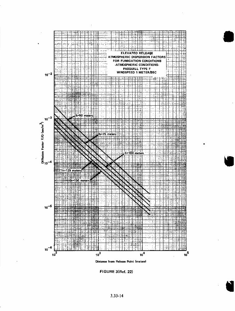
Also, special meteorological and geographical con-ditions may exist which can contribute to greaterground level concentrations in the immediateneighborhood of a stack. For example, fumigationshould always be assumed to occur; however, thelength of time that a fumigation condition exists isstrongly dependent on geographical and seasonal fac-tors and should be evaluated on an individual casebasis.7 (See Fig. 3 for elevated releases under fumiga-tion conditions.)
b. For plants with stacks, the atmospheric diffu-sion model should be as follows:
(1) The basic equation for atmospheric diffusionfrom an elevated release is
exp(-he 2/ 2oz 2)X/Q =r~
where
X = the short-term average centerline value of theground level concentration (Ci/m 3)
Q = amount of material release (Ci/sec)
tL = windspeed (m/sec)
U = the horizontal standard deviation of the plumeY (meters). (See Ref. 21, Figure V-1, p.48.)
z= the vertical standard deviation of the plume(meters). (See Ref. 21, Figure V-2, p.48.)
he = effective height of release (m)8
6 Credit for an elevated release should be given only if the point of
release is (I) more than two and one-half times the height of anystructures close enough to affect the dispersion of the plume or (2)located far enough from any structure that could have an effecton the dispersion of the plume. For these plants without stacks, theatmospheric diffusion factors assuming ground level releases, asshown in Regulatory Position 4.c, should be used.
' For sites located more than 2 miles from large bodies of water,such as oceans or one of the Great Lakes, a fumigation conditionshould be assumed to exist at the time of the accident and continuefor one-half hour. For sites located less than 2 miles from largebodies of water, a fumigation condition should be assumed to existat the time of the accident and continue for 4 hours.
I he = h, - ht, where h, is the height of the release above plantgrade and ht is the maximum terrain height, above plant grade,between the point of release and the point at which the calculationis made. ht should not be allowed to exceed h,.
I
43.33-6

(2) For time periods of greater than 8 hours, theplume from an elevated release should be assumed tomeander and spread uniformly over a 22.50 sector.9
The resultant equation is
2.032 exp( -h2 /2oz.2)x/Q = aztx
where
x = distance from the release point (meters); othervariables are as given in b(l).
(3) The atmospheric diffusion model'" for anelevated release as a function of the distance from theplant is based on the information in the table below
Time FollowingAccident Atmospheric Conditions
0 to 8 hours See Figure 4 for Envelope ofPasquill diffusion categories[based on Figure A7,Meteorology and AtomicEnergv-1968 (Ref. 15), as-suming various stack heights]windspeed I m/sec; uniformdirection.
8 to 24 hours See Figure 5 for Envelope ofPasquill diffusion categories;windspeed 1 m/sec; variabledirection within a 22.50 sector.
c. For facilities exhausted without stacks, the at-mospheric diffusion model should be as follows:
(1) The 0-to-8 hour ground level release con-centrations may be reduced by a factor ranging fromone to a.maximum of three (see Figure 6) for ad-ditional dispersion when calculating nearby potentialexposures. The volumetric building wake correctionfactor, as defined in Section 3-3.5.2 of Meteorologyand A tomnic Energy-1968 (Ref. 15), should be used inthe 0-to-8 hour period only; it is used with a shapefactor of one-half and the minimum cross-sectionalarea of a major building.
(2) The basic equation for atmospheric diffusionfrom a ground level point source is
Ix/Q = --___
9 The sector may be assumed to shift after 8 hours if localmeteorological data are available to justify a wind directionchange. This should be considered on an individual case basis.
'0 In some cases, site-dependent parameters such as meteorology,topography, and local geography may dictate the use of a morerestrictive model to ensure a conservative estimate of potential off-site exposures. Site-related meteorology should be developed on anindividual case basis. If adequate local meteorological data are notavailable, this model should be used.
where
X = the short-term average centerline value of theground level concentration (Ci/.m3 )
Q = amount of material release (Ci/sec)
ýL = windspeed (m/sec)
Cr = the horizontal standard deviation of the plume(m). (See Ref. 21, Figure V-I, p.48.)
017 = the vertical standard deviation of the plume(m). (See Ref.21, Figure V-2, p.48.)
(3) For time periods of greater than 8 hours, theplume should be assumed to meander and spread un-iformly over a 22.5' sector.' The resultant equation is
2.032x/Q- =zp-ZX
where
x = distance from point of release to the receptor;other variables are as given in c(2).
(4) The atmospheric diffusion model for groundlevel releases is based on the information in the fol-lowing table:
Time FollowingAccident
0 to 8 hours
8 to 24 hours
Atmospheric Conditions
Pasquill Type F, windspeed Im/sec, uniform direction
Pasquill Type F, windspeed Im/sec, variable directionwithin a 22.50 sector.
(5) Figures 7A and 7B give the ground levelrelease atmospheric diffusion factors based on theparameters given in c(4).
D. IMPLEMENTATION
.The purpose of this section is to provide informa-tion to applicants and licensees regarding the staffsplans for using this regulatory guide.
Except in those cases in which the applicantproposes an alternative method for complying withspecified portions of the Commission's regulations,the method described herein will be used in theevaluation of submittals for operating license or con-struction permit applications docketed afterDecember 1, 1977.
If an applicant wishes to use this regulatory guidein developing submittals for applications docketed onor before December 1, 1977, the pertinent portionsof the application will be evaluated on the basis ofthis guide.
3.33-7

REFERENCES
1. W. R. Stratton, "Review of Criticality Incidents,"LA-361 1, Los Alamos Scientific Laboratory (Jan.1967).
2. T. G. Hughes, "Criticality Incident at Windscale,"Nuclear Engineering International, Vol. 17, No. 191,pp.95-7 (Feb. 1972).
3. E. R. Woodcock, "Potential Magnitude ofCriticality Accidents," AHSB(RP)R-14, UnitedKingdom Atomic Energy Authority.
4. M.S. Dunenfeld, R. K. Stitt, "Summary Reviewof the Kinetics Experiments on Water Boilers,"NAA-SR-7087, Atomic International (Feb. 1973).
5. P. Lcorch6, R. L. Seale, "A Review of the Experi-ments Performed to Determine the RadiologicalConsequences of a Criticality Accident," Y-CDC-12,Union Carbide Corp. (Nov. 1973).
6. G. Tuck, "Simplified Methods of Estimating theResults of Accidental Solution Excursions," Nucl.Technol., Vol. 23, p. 17 7 (1974).
7. A. R. Olsen, R. L. Hooper, V. 0. Uotinen, C. L.Brown, "Empirical Model to Estimate EnergyReleases from Accidental Criticality," ANS Trans.,Vol. 19, pp. 189-91 (1974).
8. T. F. Wimmette et al., "Godiva 2-An Un-moderated Pulse Irradiation Reactor," Nucl. Sci.Eng., Vol. 8, p.6 9 1 (1960).
9. W. E. Nyer, G. 0. Bright, R. J. McWhorter,"Reactor Excursion Behavior," InternationalConference on the Peaceful Uses of Atomic Energy,paper 283, Geneva (1966).
10. E. D. Clayton, "Anomalies of Criticality," Nucl.Technol., Vol. 23, No. 14 (1974).
11. M. J. Bell, "ORIGEN-The ORNL IsotopeGeneration and Depletion Code," ORNL-4628, OakRidge National Laboratory (May 1973).
12. R. 0. Gumprecht, "Mathematical Basis of Com-puter Code RIBD," DUN-4136, Douglas UnitedNuclear, Inc. (June 1968).
13. The Effects of Nuclear Weapons, Revised Ed.,Samuel Glasstone, Editor, U.S. Depart. of Defense(Feb. 1964).
14. "Permissible Dose for International Radiation,"Publication 2, Report of Committee II, InternationalCommission on Radiological Protection (ICRP),Pergamon Press (1959).
15. Meteorology and Atomic Energy-I1968, D. H.Slade, Editor, U.S. Atomic Energy Commission (July1968).
16. C. M. Lederer, J. M. Hollander, I. Perlman,Table of Isotopes, 6th Ed., Lawrence RadiationLaboratory, Univ. of California, Berkeley, CA.
17. Radiation Dosimetry, G. J. Hine and G. L.Brownell, Editors, Academic Press, New York(1956).
18. Recommendations of ICRP, Publication 6,Pergamon Press (1962).
19. "The Metabolism of Compounds of Plutoniumand Other Actinides," a report prepared by a TaskG -- of Committee 1I, ICRP, Pergamon PresstMay 1972).
20. J. R. Houston, D. L. Strenge, and E. C. Watson,"DACRIN-A Computer Program for CalculatingOrgan Dose from Acute or Chronic RadionuclideInhalation," BNWL-B-389(UC-4), BattelleMemorial Institute, Pacific Northwest Laboratories,Richland, WA.(Dec.1974).
21. F. A. Gifford, Jr., "Use of RoutineMeteorological Observations for Estimating At-mospheric Dispersion," Nuclear Safety, Vol. 2, No.4, p.48 (June 1961).
22. Regulatory Guide 1.3, "Assumptions Used forEvaluating the Radiological Consequences of a Lossof Coolant Accident for Boiling Water Reactors,"U.S. Nuclear Regulatory Commission, Washington,D.C.
to
l3.33-8

TABLE 1
ASSUMED FISSION PRODUCT AND TRANSURANICNUCLIDE RADIOACTIVITY IN SPENT FUEL SOLUTION
PRIOR TO CRITICALITY INCIDENT
3.3% Enriched Fuel Irradiated to 33000 MWd/MTU,cooled 150 days and calculated by ORIGEN code.
NUCLIDE
TritiumStrontium-89Strontium-90Yttrium-90Yttrium-991Zirconium-95Niobium-95Ruthenium- 103Rhodium-103MRuthenium-106Rhodium-106Iodine-129Iodine-131Xenon-131mCesium- 139Cesium- 137Barium- 137MCerium-141Cerium-144Praseodymium-144Promethium- 147Europium- 154Plutonium-238Plutonium-239Plutonium-240Plutonium-241Americium-241Curium-242Curium-244
CURIES/LITER
2.9E- I4.0E+ 13.2E+13.2E+ I
*5.7E+ I1.2E+22.2E+23.7E+ 13.7E+ I1.7E+21.7E+21.6E - 59.1E -4.4E - 3
9.OE+ I4.5E+14.2E+ I2.4E+ I3.2E+23.2E+24.2E+ I2.3E 01.2E 01.4E- I2.OE - 14.8E+I8.4E - 26.3E 0L.OE 0
3.33-9

TABLE 2
RADIOACTIVITY OF IMPORTANT NUCLIDES RELEASEDFROM THE CRITICALITY ACCIDENT IN THIS GUIDE (Ci)
NUCLIDE 0 to 0.5 hr 0.5 to 8 hr TOTAL 0Kr-83m 3.7E 0 3.3E+ 1 3.7E+ IKr-85m 1.6E+ 1 1.5E+2 1.7E+2Kr-85 1.5E-4 1.4E-3 1.6E-3Kr-87 1.0E+2 9.OE+ 2 1.0E+3Kr-88 6.5E+ 1 5.9E+2 6.6E+2Kr-89 4.1E+3 3.7E+4 4.1E+4
Xe-131m 3.8E-4 3.5E-3 3.9E-3Xe-133m 5.5E-2 4.9E-1 5.5E-1Xe-133 1.3E 0 1.2E+ I 1.3E+ 1Xe-135m 1. IE+ 1 9.9E+1 1.1E+2Xe-135 1.6E+ 1 1.5E+2 1.7E+2Xe-137 3.8E+3 3.5E+4 3.9E+4Xe-138 1.2E+3 1.0E+4 1.IE+4
1-129 4.2E-I 1 3.9E-10 4.3E-101-131 1.8E-1 1.6E0 1.8E01-132 6.7E-1 6.1E0 6.7E01-133 3.5E0 3.1E+I 3.5E+11-134 4.8E+ I el '-+2 4.8E+21-135 1.2E+1 1.OE+2 1.2E+2
3.33-10

TABLE 3
VALUES OF THE CLEARANCE PARAMETERS FOR THETASK GROUP LUNG MODELa
COMPA RTMENT
NP
TB
CLASS Db, c CLASS Wc CLASS yc
Tk d
a 0.01
b 0.01
c 0.01
fkd
0.5
0.5
0.95
Tkd
0.01
fkd
0.1
Tkd
0.01
fk d
0.01
0.4 0.9 0.4 0.99
0.01 0.5 0.01 0.01
P
d 0.2 0.05
e 0.5 0.8
f n.a.e n.a.e
g n.a.e n.a. e
h 0.5 0.2
i 0.5 1.0
0.2 0.5 0.2 0.99
50 0.15 500 0.05
1.0 0.4 1.0 0.4
50
50
50
0.4
0.05
1.0
500
500
1000
0.4
0.15
0.9L
a See Figure 2 for the task group lung model (TGLM) schematic diagram.
b Data for soluble plutonium are included. To maintain dose conversion conservatism, this class should only be considered if justified on anindividual case basis.
c Class D = readily soluble compounds where removal time is measured in days.
Class W = compounds with limited solubility where removal time is measured in weeks.
d Class Y = insoluble compounds where removal time is measured in years.T k is the biological removal half time in days; fk is the fraction of original deposit leaving the organ via pathway indicated on the schematic modelshown in Figure 2. Data are based on a mass median aerodynamic diameter of I micron and were developed by Battelle Memorial Institute, PacificNorthwest Laboratories, and presented in an interim report by E.C. Watson, J. R. Houston, and D. L. Strenge, April 1974.
e n.a. means not applicable.
3.33-11

1.0
10 -1
0 c
102
,00 1 :41 / 01 f-~-
'": I / Y
0i /1
ii /0i54
il
0.1 1.0 10
Maximum Beta Energy, MeV
RATIO OF DEPTH DOSE TO SURFACE DOSE AS A FUNCTION BETA ENERGY SPECTRA1
for Infinite Plane Source of Infinite Thickness and for Allowed Spectra
Developed from Considerations Presented in Reference 17, Chapter 16
FIGURE 1
I3.33-12

I j LYMPH I
SCHEMATIC DIAGRAM DEVELOPED FROM ICRP TASK GROUP LUNG MODEL (Ref. 19)
FIGURE 2
3.33-13
- -T
a s . O w I .
110-3 1 i------
.... i.,
lip. .. I
.2
' •h~lO0 meters.
S10-
10-4 10 10
10 A.i j ; j:A iliý102 10 104 105
Distance from Release Point (meters)
FIGURE 3(Ref. 22)
U3.33-14

.... .• .i- :-'" i_ .. . .. 7 "- . ... 7 "~ l [ 7--
......._.._• -- !• -72¶:7.•• _ -.T7-7-.K.I -7, --
•--•"•-7 ........ ELEVATED ýRELEASE i[..
I ATMOSPHERIC DIFFUSION FACTORS
l0-8 HOUR RELEASE TIME
l O 5 1 1 1 1 i r - ý 1 1ý% --. • -II ,--4r
Sh=125 meters•,- 1. 1
Uo--L.
156o-8tC -Ihl5metersi.
- -
-I- 7-A
10-8
102 103 104
Distance from Release Point (meters)
FIGURE 4(Ref. 22)
3.33-15

l0
C4
ILLI
h=t50 m•trs10-
a. Lill 'P,,M f ý1WM.
Dis =25m taefrmRlaePit(ters~
1 41fIGURET 5(r. 22)L 4
M .- Tt N.... ..
0-74
10 - 11 li p.102 0 104 105 i jI iHU
Distance ~glu fro ReesePinimees
F~IG R H. ef I 2 t~t~th
3.33-16

V1 U S!
J• 01I I I I I I I I
~.i.I.I.
* I
* .1-tIt il i
!l:ll!l:l
I I. ... ,:,,:I;vI::;.;: :1;V
I: ii, 4
Til
3
2.5
2
0
C
1.5
• 01
______________________________
1- __.11__
!1.11 IT Ma.
\ \I \\\\i
Ii
I]
,, !i H±F11!!P1I
111 F1
BUILDING WAKECORRECTION FACTOR' i T
IT
11fl Ii
- 0.5A=500 meters2/ •'". *
- -- 1--•-_5-1 meters
S0.5A=1500- me
K 20 .5A=2000 meters
,!,,,.
0.5A=250-0mete'rs"V-
-OloA=3o00 meter7 L1
IiI ir~ -h I-h-I
N N r f+I-viDO.
0.5
7-I J
vizi~ i Lvi-7LL• L!
I..1 M il-Fr
•'-'i '•!•-HL T:7 T"i
102
+4103
Distance from Structure (meters)
FIGURE 6(Ref. 22)

F
10- 2
10- 3
U.
U-
.2
IIEThEfEFEF3IIWk:I I I I I III I I111 I ; -II
I L L . .. .I ,- , --1 1 .1 1 1 1 1 1 1 1 1 1 1 I I . I i .
[i!:•,i!i:1 1 I I 1 1 llII 9LFL
GROUND LEVEL RELEASE
ATMOSPHERIC DIFFUSION FACTORS FOR --
VARIOUS TIMES FOLLOWING ACCIDENT
1144144Jb • [ I • i I f [
it I it ,
N'Fin• -:- ] " •. " ]•.1 -4---F•
N=.N -h
-L H
T II
.... - tT
8--24 hours
L_ -- It
it* L.
L1112
F-.-
-T-H
- i:P7
R
._1..* -- - 1~~*~~
I
N I I I
-jLW10-5 I
10 2 104Distance from Structure (meters)
FIGURE 7A(Ref. 22)
U3.33-18

10-5
10-6
U.
2
th -1--x 1127 I I f . I *I I I I
GROUND LEVEL RELEASE-ATMOSPHERIC DIFFUSION FACTORS FOR- VARIOUS TIMES FOLLOWING ACCIDENT
N .I IIII 1-T_
-24hot
_7
N 1-8 hours
rs S
-F -~
I --
-1--IN
K4' IEH7 -t
II IL - zt--n 3' , !---- i
7-
HF
i ,- -- -i i -+- +-
1'2- I
1 1 1 1 1 11 Il I I I . -1-1-1 1 ITT 1 1 1 ý I 1 1 1 1 1
----- I---
I ... . . . --
__ .1
L-7. 1 .
-Ijjl---iFii-Ii
I -
1%
10-810E
I I* II I .1.1.1 .....~........F..i3
Distance from Structure (meters)106
FIGURE 7B(Ref. 22)
3.33-19

UNITED STATESNUCLEAR REGULAfORY COMMISSION
WASHINGTON. D. C. 20565
OFFICIAL BUSINESSPENALTY FOR PRIVATE USE, $300
POSTAGE AND FEES PAIDU.S. NUCLEAR REGULATORYCOMMISSION
19406002001 SF 0477U S NRCOFFICE OF INSPECTION & ENFORCER J BORES631 PARK AVENUE
KING OF PRUSSIA PA 19406
A

1/8/73U.S. ATOMIC ENERGY COMMISSION
REGULATORYDIRECTORATE OF REGULATORY STANDARDS
GUIDE
REGULATORY GUIDE 3.3
QUALITY ASSURANCE PROGRAM REQUIREMENTSFOR FUEL REPROCESSING PLANTS
A. INTRODUCTION
Appendix B to 10 CFR Part 50, "Quality AssuranceCriteria for Nuclear Power Plants and Fuel ReprocessingPlants." establishes quality assurance requirements forthe design., construction, and operation of nuclear powerplant and fuel reprocessing plant structures, systems andcomtxmnents. This regulatory guide describes anacceptable method of complying with the Commission'sregulations with regard to overall quality assuranceprogram requirements for fuel reprocessing plants.
B. DISCUSSION
Subcommittee N45-3, Nuclear Quality AssuranceStandards, (formerly ad hoc Committee N45-3.7) of theAmerican National Standards Institute, StandardsCommittee N45. Reactor Plants and Their Main tenance,under the sponsorship of the American Society ofMechanical Engineers, has developed a standard whichincludes general requirements and guidance for theestablishment and execution of quality assuranceprogramis during the design, construction, and operationphases of nuclear power plants. This standard wasapproved by the American National StandardsCommittee N45 and its Secretariat, and it wassubsequently approved and designated N45.2-1971 bythe American National Standards Institute on October20. 1972.
This standard is adaptable to fuel reprocessing plantsas it was prepared to satisfy the. intent and amplify therequirements of AEC quality assurance regulations andprovides general requirements and guidance forestablishment and execution of quality assuranceprograms.
C. REGULATORY POSITION
The general requirements and guidelines forestablishing and executing quality assurance programsfor nuclear power plants which are included in ANSIN45.2-197 I, "Quality Assurance Program Requirementsfor Nuclear Power Plants"'' may be adapted to fuelreprocessing plants and are generally acceptable andprovide an adequate basis for complying with theprogram requirements of Appendix B to 10 CFR Part50, applicable to fuel reprocessing plants. When adaptingANSI N45.2-1971 to fuel reprocessing plants the termfuel reprocessing plants should be substituted asapplicable wherever specific reference is made to theterm nuclear power plant(s).
'Copies may be obtained from the American Society ofMechanical Engineers. United Engineering Center, 345 East 47thStreet, New York, N.Y. 10017.
USAEC REGULATORY GUIDES Copies of published guides may be obtained by request indicating the divisionsdesired to the US. Atomic Energy Commission, Washington, D.C. 20545,
Regulatory Guides are issued to describe and make available to the public Attention: Director of Regulatory Standards. Comments and suggestions formethods acceptable to the AEC Regulatory staff of implementing specific parts of improvements in these guides are encouraged and should be sent to the Secretarythe Commission's regulations, to delineate techniques used by the staff in of the Commission, U.S. Atomic Energy Commission, Washington, nDC. 20545,evaluating specific problems or postulated accidents, or to provide guidance to Attention: Chief, Public Proceedings Staff.applicants. Regulatory Guides are not substitutes for regulations and compliancewith them is not required. Methods and solutions different from those set Out in The guides are issued in the following ten broad divisions:the guides will be acceptable if they provide a basis for the findings requisite tothe issuance or continuance of a permit or license by the Commission. 1. Power Reactors 6. Products
2. Research and Test Reactors 7. Transportation3. Fuels and Materials Facilities S. Occupational Health
Published guide5 will be revised periodically, as appropriate, to accommodate 4. Environmental and Siting 9. Antitrust Reviewcomrrsetts and to reflect new information or experience. 6. Materials and Plant Protection 10. General