COP8 Trenching
32
Code of Practice – (No. 8) – Safety Precautions in Trenching Operations 01 September 1988 Uncontrolled Copy Printed on 26/07/01 Copyright Victorian WorkCover Authority Melbourne Australia 1 What is a Code of Practice? The term ‘Code of Practice’ has a particular meaning under the Victorian Occupational Health and Safety Act 1985. Other Codes of Practice, such as the advisory codes developed by the National Occupational Health and Safety Commission, voluntary codes agreed in an industry, or codes adopted by other states or countries do not come within the meaning of the term used in the Victorian Act. Codes of Practice are developed by the Victorian Occupational Health and Safety Commission with assistance from the Department of Labour. The Commission is made up of employer, union, expert and government representatives. The Commission recommends the Code of Practice to the Minister for Labour for approval after a period of public review of the draft, and consideration of any comment received. The Victorian Occupational Health and Safety Act 1985 provides for Codes of Practice “for the purpose of providing practical guidance to employers, self- employed persons and employees,...” (S.55[1]). A Code of Practice approved by the Minister for Labour comes into effect when “notice of approval is published in the Government Gazette or on such later day as may be specified in the notice,...” (S.55[6]). A Code of Practice does not have the same legal force as Regulations. Contravention of, or failure to comply with, Regulations made under the Act is an Offence (S.47[l]). Failure to observe a provision of an approved Code of Practice is not in itself a breach of the Act (S.55[8]). However, in proceedings under the Act, where it is alleged that a person contravened or failed to comply with a provision of the Act or the regulations, a relevant approved Code of Practice is admissible as evidence. The court is required to take the matter as proved unless the person is able to show that compliance with the Act or regulations was achieved in some way other than that provided in the approved Code of Practice (S.56). A Health and Safety Representative is able to cite an approved Code of Practice in a Provisional Improvement Notice as a means by which the alleged non-compliance may be overcome. Similarly, an Inspector may cite an approved Code of Practice together with the relevant Section of the Act or regulations when issuing an Improvement Notice or Prohibition Notice. In situations where it is impracticable to comply with the literal provisions of a Code the employer must be able to show that an equivalent or better level of health and safety results from the alternative action taken. In summary, an approved Code of Practice: • provides practical guidance; • should be followed, unless there is another solution which achieves the same result, or a better solution; • is able to be used in support of the Act’s preventive enforcement provisions; and • can be used to support prosecution. This publication is copyright. No part may be reproduced by any process except in accordance with the provisions of the Copyright Act 1968. Copyright Victorian WorkCover Authority Melbourne Australia First published 1988; Reprinted 1995, 1996, 1997. ISBN 0 7241 7132 0 Sales: WorkCover Victoria Level 3, 485 Latrobe Street, Melbourne. (03) 9641 1555
-
Upload
thillai-nathan -
Category
Documents
-
view
35 -
download
0
description
Trenching safety precautions
Transcript of COP8 Trenching

Code of Practice – (No. 8) – Safety Precautions in Trenching Operations 01 September 1988
Uncontrolled Copy Printed on 26/07/01 Copyright Victorian WorkCover Authority Melbourne Australia 1
What is a Code of Practice?
The term ‘Code of Practice’ has a particular meaning under the Victorian Occupational Health and Safety Act 1985. OtherCodes of Practice, such as the advisory codes developed by the National Occupational Health and Safety Commission,voluntary codes agreed in an industry, or codes adopted by other states or countries do not come within the meaning of theterm used in the Victorian Act.
Codes of Practice are developed by the Victorian Occupational Health and Safety Commission with assistance from theDepartment of Labour.
The Commission is made up of employer, union, expert and government representatives. The Commission recommends theCode of Practice to the Minister for Labour for approval after a period of public review of the draft, and consideration of anycomment received.
The Victorian Occupational Health and Safety Act 1985 provides for Codes of Practice “for the purpose of providingpractical guidance to employers, self- employed persons and employees,...” (S.55[1]).
A Code of Practice approved by the Minister for Labour comes into effect when “notice of approval is published in theGovernment Gazette or on such later day as may be specified in the notice,...” (S.55[6]).
A Code of Practice does not have the same legal force as Regulations. Contravention of, or failure to comply with,Regulations made under the Act is an Offence (S.47[l]). Failure to observe a provision of an approved Code of Practice isnot in itself a breach of the Act (S.55[8]).
However, in proceedings under the Act, where it is alleged that a person contravened or failed to comply with a provision ofthe Act or the regulations, a relevant approved Code of Practice is admissible as evidence. The court is required to take thematter as proved unless the person is able to show that compliance with the Act or regulations was achieved in some wayother than that provided in the approved Code of Practice (S.56).
A Health and Safety Representative is able to cite an approved Code of Practice in a Provisional Improvement Notice as ameans by which the alleged non-compliance may be overcome. Similarly, an Inspector may cite an approved Code ofPractice together with the relevant Section of the Act or regulations when issuing an Improvement Notice or ProhibitionNotice.
In situations where it is impracticable to comply with the literal provisions of a Code the employer must be able to show thatan equivalent or better level of health and safety results from the alternative action taken. In summary, an approved Code ofPractice:
• provides practical guidance;• should be followed, unless there is another solution which achieves the same result, or a better solution;• is able to be used in support of the Act’s preventive enforcement provisions; and• can be used to support prosecution.
This publication is copyright. No part may be reproduced by any process except in accordance with the provisions of theCopyright Act 1968. Copyright Victorian WorkCover Authority Melbourne Australia
First published 1988; Reprinted 1995, 1996, 1997. ISBN 0 7241 7132 0Sales: WorkCover Victoria Level 3, 485 Latrobe Street, Melbourne. (03) 9641 1555

Code of Practice – (No. 8) – Safety Precautions in Trenching Operations 01 September 1988
Uncontrolled Copy Printed on 26/07/01 Copyright Victorian WorkCover Authority Melbourne Australia 2
1. Authority
This Code of Practice is approved pursuant to Section 55 of the Occupational Health and Safety Act l985 (theAct) and shall have effect from September 1st, 1988.
2. Section 21 of the Act requires an employer, among other things, to ‘provide and maintain so far as ispracticable for employees a working environment that is safe and without risks to health’ and "to provide andmaintain plant and systems of work that are so far as is practicable safe and without risks to health".
3. Purpose
The purpose of this Code of Practice is to provide practical guidance on measures to be taken to prevent injuryto persons engaged in trenching work.
4. Scope
The planning, preparation, and conduct of work practices in connection with the excavation, maintenance andbackfilling of trenches.
5. Mines (Trenches) Regulations 1982
Users of this Code of Practice should note that unless specifically exempted any trench more than 1.5 metres indepth in which a pipe or cable is to be laid is subject to the provisions of the Mines Act 1958 and the Mines(Trenches) Regulations 1982.
Those regulations contain provisions relating to the duties and responsibilities of persons in charge of thetrenching activities.
Under the Occupational Health and Safety Act 1985 the employer has primary responsibility to “provide andmaintain so far as is practicable for employees a working environment that is safe and without risks to health”.In acknowledgment of the mandatory requirement for compliance with the Mines (Trenches) Regulations 1982under the prescribed circumstances, the Code of Practice does not imply any delegation of that primaryemployer responsibility.
It is important to note that non-compliance with the Mines Act or the Mines (Trenches) Regulations can lead toprosecutions under both the Mines Act 1958 and the Occupational Health and Safety Act 1985.

Code of Practice – (No. 8) – Safety Precautions in Trenching Operations 01 September 1988
Uncontrolled Copy Printed on 26/07/01 Copyright Victorian WorkCover Authority Melbourne Australia 3
1. Site Investigations
1.1 Before commencing work, contractors and constructing authorities should obtain as much information aspossible about the ground conditions of a work site.
1.2 Source of Information
1.2.1 Natural features such as rock outcrops, water-courses, creeks and swamps should be inspected. The surfacedrainage system should also be studied in relation to the line of the proposed excavation.
1.2.2 Information on ground conditions may be available from nearby works such as existing railway cuttings,roadways, and foundation works.
1.2.3 Results of any test bores are usually available from the appropriate authorities. When they are not available,unsupported test excavations using a backhoe should be dug in doubtful areas to observe ground conditionsand determine suitable ground support systems.
1.3 Factors To Consider
1.3.1 When deciding upon a system of support, the employer in charge of an excavation should consider thefollowing factors:
(a) Nature of the ground:• soil or rock type;• moisture content of the rock or soil: is it wet or dry? If dry, will its cohesive characteristics
deteriorate when it becomes wet? If wet, will water control be required?;• water table level;• faults and bedding planes.
(b) Possibility of flooding from any water source:• storm water drain;• surface run-off after heavy rain;• swamp, dam, reservoir or lake;• river.
Flooding can be sudden and tragic, so precautions should be taken, which could include drainage run-offcontrol and availability of pumps on site.
(c) Proximity of underground services such as gas, electricity, sewer, water mains or telephone cables.Enquires should be made to the appropriate authority in regard to location of services prior to excavation,or refer to the booklet “Dial Before You Dig” obtainable from the Local Government Department on 6029411. Previously dug excavations have a weakening effect on a trench wall if they are in close proximity,close sheeting may therefore be necessary. (See Figure 1.)
(d) Point sources of instability which may require additional local support. Close sheeting should be usedin unstable ground, reverting to soldier sets when the excavation has progressed to more stable ground.

Code of Practice – (No. 8) – Safety Precautions in Trenching Operations 01 September 1988
Uncontrolled Copy Printed on 26/07/01 Copyright Victorian WorkCover Authority Melbourne Australia 4
(e) Hazards, natural or artificial (Fig. 1):• intersecting old service excavations;• telephone and electricity supply poles;• Manholes and other shafts;• bends in an excavation;• leaking services;• corners created by the joining of pipe systems, ie. "T", "Y", or "+" junctions• trees;• the threat to health and safety from the past dumping of chemicals
(a) Sectional view of old and new excavation. Old Excavation may be waterlogged or the fill my not haveconsolidated. Where only a relatively thin wall of undisturbed material separates the two excavations, thisbarrier may be under increased side pressure and, therefore, more likely to collapse.
1) Side pressure from higher pipe2) Current open excavation3) Trench depths may differ4) Side pressure from thin section of undisturbed wall.

Code of Practice – (No. 8) – Safety Precautions in Trenching Operations 01 September 1988
Uncontrolled Copy Printed on 26/07/01 Copyright Victorian WorkCover Authority Melbourne Australia 5
Figure 1Working Close to Disturbed Ground.Additional care should be taken where disturbed ground may exist due to previously worked trenches or shafts.In such cases, it is essential to increase the excavation ground supports or use a correctly designed andfabricated shield.

Code of Practice – (No. 8) – Safety Precautions in Trenching Operations 01 September 1988
Uncontrolled Copy Printed on 26/07/01 Copyright Victorian WorkCover Authority Melbourne Australia 6
(f) Static loads near an excavation, including:• the spoil pile;• an excavation in wet clay, 3.0 metres deep by 1.0 metre wide, will create a spoil pile having
a mass of approximately 6 tonnes per metre of excavation. This must be considered whendesigning a support system if the spoil pile is located near the trench (see Section 7,Cohesive Strength and Earth Pressures);
• buildings, including garages and outbuildings;• water tanks or towers;• brick or stone walls;• embankments;• dams.
In case of static loads nearby, additional timber supports should be installed.
(g) Dynamic loads near an excavation, such as:• traffic (highway and rail);• excavation equipment.
(h) Ground vibration. Occasionally, the collapse of a trench is caused nor by dynamic loads but by theaccompanying ground vibration. Such vibration may come from:
• heavy traffic;• rail stock passing close to an excavation;• excavation machinery;• construction works in the immediate vicinity (eg. pile driving);• explosives use.
1.3.2 The hazards of working close to previously disturbed ground are considerably increased when the ground iseither very wet or very dry. Under these conditions it may be necessary to use sheet piling or employ a shieldor cage to ensure safe working conditions.
1.4 Better Safe Than Sorry
1.4.1 Where the trenching work is at a remote location effective means of communication such as a telephone ortwo-way radio should be available to call for advice in case of problems or to call for help in emergencies.
1.4.2 In all cases, if there is any uncertainty about the minimum amount of safe trenching support, it is better to playsafe and:
• batter the excavation;• over-design the support;• obtain competent professional advice.
1.4.3 It will pay in the long run to build extra safety features into the support system rather than to under-design thesupports and increase the risk of accidents.
Code of Practice – (No. 8) – Safety Precautions in Trenching Operations 01 September 1988
Uncontrolled Copy Printed on 26/07/01 Copyright Victorian WorkCover Authority Melbourne Australia 7
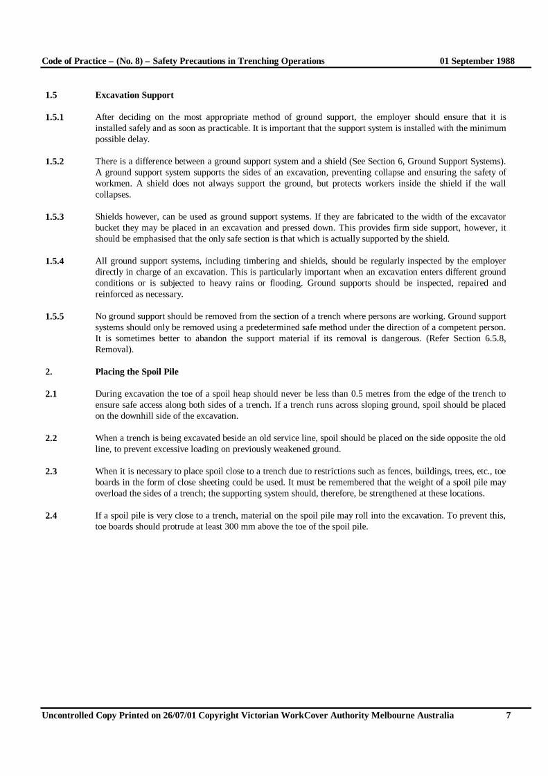
1.5 Excavation Support
1.5.1 After deciding on the most appropriate method of ground support, the employer should ensure that it isinstalled safely and as soon as practicable. It is important that the support system is installed with the minimumpossible delay.
1.5.2 There is a difference between a ground support system and a shield (See Section 6, Ground Support Systems).A ground support system supports the sides of an excavation, preventing collapse and ensuring the safety ofworkmen. A shield does not always support the ground, but protects workers inside the shield if the wallcollapses.
1.5.3 Shields however, can be used as ground support systems. If they are fabricated to the width of the excavatorbucket they may be placed in an excavation and pressed down. This provides firm side support, however, itshould be emphasised that the only safe section is that which is actually supported by the shield.
1.5.4 All ground support systems, including timbering and shields, should be regularly inspected by the employerdirectly in charge of an excavation. This is particularly important when an excavation enters different groundconditions or is subjected to heavy rains or flooding. Ground supports should be inspected, repaired andreinforced as necessary.
1.5.5 No ground support should be removed from the section of a trench where persons are working. Ground supportsystems should only be removed using a predetermined safe method under the direction of a competent person.It is sometimes better to abandon the support material if its removal is dangerous. (Refer Section 6.5.8,Removal).
2. Placing the Spoil Pile
2.1 During excavation the toe of a spoil heap should never be less than 0.5 metres from the edge of the trench toensure safe access along both sides of a trench. If a trench runs across sloping ground, spoil should be placedon the downhill side of the excavation.
2.2 When a trench is being excavated beside an old service line, spoil should be placed on the side opposite the oldline, to prevent excessive loading on previously weakened ground.
2.3 When it is necessary to place spoil close to a trench due to restrictions such as fences, buildings, trees, etc., toeboards in the form of close sheeting could be used. It must be remembered that the weight of a spoil pile mayoverload the sides of a trench; the supporting system should, therefore, be strengthened at these locations.
2.4 If a spoil pile is very close to a trench, material on the spoil pile may roll into the excavation. To prevent this,toe boards should protrude at least 300 mm above the toe of the spoil pile.

Code of Practice – (No. 8) – Safety Precautions in Trenching Operations 01 September 1988
Uncontrolled Copy Printed on 26/07/01 Copyright Victorian WorkCover Authority Melbourne Australia 8
3. Daily Inspections: What to Watch For
3.1 In the course of daily routine inspections the employer in charge should watch for certain unsafe situationswhich are common during excavating, pipe laying and backfilling. Surveillance of trench walls and supportsystems should be carried out frequently to ensure that:
• the trench sides are not being undercut by the excavator bucket;• the supports are not being overstressed;• the ground is not fretting or beginning to collapse into the trench;• tension cracks do not appear along the trench top• the trench walls do not sag under the increased pressure of the excavator (Fig. 2)
3.2 Pipes, which are to be laid, and equipment for laying pipes (shovels, hunching materials, etc) should be placedaway from the top of the trench to ensure that they do not fall in (Fig. 3)
3.3 Safety Helmets
3.3.1 It is important for persons in and around trenches to wear safety helmets. The absence of a safety helmet is notonly a breach of the Mines (Trenching) Regulations, but a dangerous practice. A falling hammer, weighing only500 g will hit a worker three metres below in less than a second, with an average impulsive force of 50 kg:enough to cause serious concussion or even death if they are not wearing a safety helmet. The Mines(Trenching) Regulations require all persons on site to wear a safety helmet, whether they are involved in thework directly, inspecting the excavation or simply touring the area.

Code of Practice – (No. 8) – Safety Precautions in Trenching Operations 01 September 1988
Uncontrolled Copy Printed on 26/07/01 Copyright Victorian WorkCover Authority Melbourne Australia 9
3.4 Treading in Dangerous Ground
3.4.1 Work must never proceed in potentially unstable, unsupported ground (Fig 4). Working without installingsupports may appear to hasten the excavation process, but a substantial fall of ground will delay operations,and, if a fall of earth results in the injury or death of a worker, further delays will occur during investigations.
3.4.2 If workers are required to enter a trench before permanent support have been correctly installed (eg. to drilland place explosives), temporary protection in the form of timber supports or shields should be used. Thesesupports are necessary because vibration from drilling equipment may cause the ground to collapses.
3.4.3 Another common and dangerous procedure is the practice of entering an unsupported section of trench to erector dismantle a ground support system prior to backfilling it is a mistake to believe that trench walls will notcollapse during the short time needed to erect or dismantle support. Numerous deaths and injuries haveoccurred at such times.
In fact, a trench wall is most insecure when the ground support are being erected and dismantle. During the erectionof supports, the trench has just been excavated, and the ability of the trench walls to support the load may bedecreasing with time.
There is no guarantee that the trench sides will not collapse at this time. If ground does fall, it may collapse back tothe last set; when workers stand in front of this last set they are standing in unsupported ground and are taking aconsiderable risk.
When a ground support system is being dismantled and the excavation has not been properly backfilled, the trenchwalls may not withstand the increase in side pressure that was previously borne by the ground supports. This maycause the trench to collapse.
3.5 Use Ladders, not Soldiers
3.5.1 Some workers may be in the habit of using soldiers sets as a means of entering or leaving an excavation (Fig5). This is an unsafe practice and should be avoided.

Code of Practice – (No. 8) – Safety Precautions in Trenching Operations 01 September 1988
Uncontrolled Copy Printed on 26/07/01 Copyright Victorian WorkCover Authority Melbourne Australia 10
3.5.2 When climbing up a soldier set, a worker assumes that all the toms are securely in place and will not shift orpull out, however, there is no guarantee of this. The trench walls may have shifted, thereby loosening the toptom, or the soldier set may have been erected incorrectly. In either case, the worker, when climbing out of thetrench, may use a loose tom to lift themselves up and fall back into the trench and be injured. Should thesoldier set become damaged and weakened during such an accident, the trench may collapse and causeadditional injury.
3.5.3 Access ladders should be provided in all trenches where employees are working.
3.6 Do Not Work AlonePersons should not work alone in a trench unless there is another person close by who can render aid ifnecessary. Working alone in a trench is a breach of the Mines (Trenches) Regulations 1982.
4. Danger Signs
4.1 All workers in and around a trench should be continually alert to the following danger signs:
(a) If the top edge of a trench is fretting away and dropping into a trench (Fig. 6) it could create a hazardoussituation:
• rocks may fall onto workers below;• the fretting may indicate that a more serious wall collapse is imminent;• small material rolling into the trench may cause eye damage.
(b) A slump in the surface near an excavation (Fig. 7) indicates that the wall is subsiding behind the groundsupport system. Ground subsidence behind the supports is also indicated by:
ground swelling up from the bottom of a trench;water running into an excavation from the bottom of trench supports or from between sheet piling.
These two indications of subsidence behind ground supports must be investigated to determine whether thetrench support system is being undermined. If material is being washed away from behind, the supports willbecome loose, resulting in an unsupported trench wall which can lead to a serious trench collapse.
(c) Tension cracks opening in the surface ground and running parallel to the sides of a trench.
(d) Support timbers bowing or creaking (Fig. 8).
(e) Intersected joints in the walls of a trench, which create local unsupported wedges.

Code of Practice – (No. 8) – Safety Precautions in Trenching Operations 01 September 1988
Uncontrolled Copy Printed on 26/07/01 Copyright Victorian WorkCover Authority Melbourne Australia 11
Danger Signs
Notify the employer in charge prior to taking remedial action if any of these situations are noticed:
Figure 6EARTH FRETTING OR BEING WASHED AWAYFROM THE SIDES OF AN EXCAVATION. Tensioncracks indicate that the ground support system is shiftingunder load because it was wither under-designed orincorrectly installed. A collapse may be imminent.
Figure 7SLUMPING ALONG THE TOP OF A TRENCH. Waterentering a trench may be eroding ground from behind theground support system. Ground swell along the bottom of atrench may mean that supports are being undermined.
These illustrations are examples of under-designed,unsafe support systems where stability cannot beguaranteed. The systems should either be strengthenedor changed.
Figure 8Timber, bowing, deflecting or creaking as a result ofswelling ground indicated a weak system which must bestrengthened to prevent ground collapse..

Code of Practice – (No. 8) – Safety Precautions in Trenching Operations 01 September 1988
Uncontrolled Copy Printed on 26/07/01 Copyright Victorian WorkCover Authority Melbourne Australia 12
5. Battered Excavations
5.1 When shields or a ground support system are not used to support an excavation in unstable ground conditions,the sides should be battered to the angle of repose of the spoil pile.
5.2 If the battered angle is higher than the angle of repose of the spoil pile, a soil mechanics analysis should beundertaken before excavation work commences.
5.3 A mound of loose soil assumes a characteristic shape. The mound has sloping sides which vary for differentmaterials. The angle which a sloping face of loose earth makes with the horizontal is known as the angle ofrepose. Approximate values of this angle for different materials are:
Clay (dry) 1: 1 Sand (clean) 1.5 : 1Clay (wet) 4: 1 Rock (decomposed) 1: 1
The presence of water has a substantial effect on the angle of repose of any material. The density of differentclasses of soils only varies from approximately 14 to 19 kN/m3, but the angle of repose for materials can varyconsiderably.

Code of Practice – (No. 8) – Safety Precautions in Trenching Operations 01 September 1988
Uncontrolled Copy Printed on 26/07/01 Copyright Victorian WorkCover Authority Melbourne Australia 13

Code of Practice – (No. 8) – Safety Precautions in Trenching Operations 01 September 1988
Uncontrolled Copy Printed on 26/07/01 Copyright Victorian WorkCover Authority Melbourne Australia 14
6. Ground Support Systems
6.1 Under no circumstances should any person enter an unsupported trench and install toms, workingfrom the bottom up.
6.2 All ground support equipment should be on site before excavation work commences.
6.3 Three principal types of support system are discussed here:• Soldier sets 6.5• Close sheeting 6.6• Shields 6.7
6.4 Timber used in ground support systems should be hardwood, minimum F8 grade.
6.5 Soldier Set
6.5.1 The most common form of trench support is the timber soldier set (Fig. 9). This system is mostly used instiff clays and in other soil types having similar properties.
6.5.2 If the excavation is timbered to achieve the required safety level, it should be remembered that thedimensions relating to timber sizes and the positioning of supports which are given here are the minimumrequirements necessary to support a vertical sided excavation 1.0 metre wide.
6.5.3 When trenching is deeper than 3.5 m, in similar ground, it is necessary to use horizontal members known aswalers. This is particularly important when an increase in pressure on the walls of a trench is likely and/orwhen transverse pressures along the side of a trench occur, ie. when excavating deeper than, but alongside,an older existing service.
6.5.4 A practical extension of this method of ground support is where fretting may occur and timber soldiers setswith plyboard bearer sheets nailed to the soldiers are used. Such a system may need either over-sized toms(ie. 100 mm x l00 mm) or steel jacks (Fig. 10), to support the load,
6.5.5 There are two safe methods of erecting soldier sets.
6.5.6 Method 1: Timber tongsThe most common method is the use of timber tongs (Fig. 11) as shown in Fig. 9. The following stepsshould be taken for safe installation of soldier sets with timber tongs.
(a) After measuring the depth of a trench, two soldiers are cut to length. The minimum length of thesoldiers should be the depth of the trench plus 500 mm. If the length of the soldiers is the same as the depthof the trench, it is extremely difficult to position them properly during assembly or extract them afterbackfilling the trench.
(b) After cutting two soldiers to the correct length, cleats are nailed to them no more than 750 mm apart.The top cleat should be no more than 300 mm below the top of the trench when the soldier is in place; thebottom cleat should be no higher than 1000 mm above the trench floor.
(c) After the cleats have been faced to the soldiers, the width of the trench is measured and the necessarynumber of toms for that soldier set are cut to length. This ensures that the toms press the soldiers firmlyagainst the excavation walls.

Code of Practice – (No. 8) – Safety Precautions in Trenching Operations 01 September 1988
Uncontrolled Copy Printed on 26/07/01 Copyright Victorian WorkCover Authority Melbourne Australia 15
(1) Spoil heap at least 500 mm clear of excavation allows access along both sides of the trench top andprevents material from the heap rolling into the trench.(2) Toms placed from the surface with special timbering tongs.(3) Soldiers must protrude 500 mm above the top of the trench.(4) Spoil heap or pile(5) Top tom no lower than 300 mm from the trench top.(6) For added side support, steel jacks may replace timber toms. Maximum spacing of steel jacks to be nomore than 1.0m if timber soldiers used.(7) Maximum spacing of toms no more than 750 mm.(8) Cleats securely nailed to soldiers before placing soldiers in trench.(9) Soldier resting securely on trench bottom(10) Maximum spacing between solider sets 1.50 m.(11) Soldier, minimum size 150 mm x 38 mm.(12) Tom, minimum size 150 mm x 39 mm.(13) Tom should be long enough to force soldiers firmly against trench sides. To prevent excessive bowingof soldiers against irregular trench sides, wood packing, between the trench wall and the solider, may beused.(14) Space between the bottom tom and trench floor should be sufficient to allow installation of a pipe:nominally, no more than 1000 mm.
Figure 9TYPICAL USE OF TIMBER SOLDIER SETS IN A TRENCH NO MORE THAN 3.5 m DEEP. Thisfigure shows the minimum support required for a trench being driven through ground of compact, stiff clays,or unweathered, silurian sediments. These support dimensions must be increased in trenches wider than 1.0metre, or where the supports shows signs of being overloaded.

Code of Practice – (No. 8) – Safety Precautions in Trenching Operations 01 September 1988
Uncontrolled Copy Printed on 26/07/01 Copyright Victorian WorkCover Authority Melbourne Australia 16
Plywood panels (sandwich sheets) should be used in variable ground conditions. In unstable ground, thepanelling should be continuous (closed sheeting). The panelling and soldiers must be pressed firmly againstthe trench sides by either expanding the steel jacks - or cutting toms of appropriate length and forcing themin place.
(1) Maximum spacing between soldiers sets, 1.25 mm(2) Top jack or tom to be no more than 300 mm from the trench top.(3) Spoil heap or pile(4) 600 mm (up to 1250 mm)(5) Depth of trench plus 300 mm(6) Spoil heap at least 500 mm clear of excavation allows access along both sides of the trench top andprevents material from the heap rolling into the trench.(7) Timber soldier set, minimum size with plywood sheeting, 150 mm x 38 mm(8) Timber tom., minimum size, 150 mm x 38 mm(9) Steel channel soldiers, 150 mm x 50 mm(10) Steel cleats welded onto soldiers before placement in trench(11) Steel trench strut replacing wood tom. Spacing between steel jacks should be no more than 1000 mm(12) Plywood panel of 20 mm minimum thickness, bolted to steel soldiers or nailed to timber soldiers.
Figure 10TYPICAL USE OF STEEL/TIMBER SOLDIER SETS WITH TIMBER PANELS IN A TRENCH NOMORE THAN 3.5 mm DEEP. This figure shows the different steel/timber soldier set combinations withminimum requirements for shallow trenches.

Code of Practice – (No. 8) – Safety Precautions in Trenching Operations 01 September 1988
Uncontrolled Copy Printed on 26/07/01 Copyright Victorian WorkCover Authority Melbourne Australia 17
(d) The two soldiers are placed opposite each other in the trench with the cleats at the same height toensure the tom will be horizontal. Timber tongs are used to lower the tom into the trench with the lowerend of the tom being placed on top of the far side bottom cleat. The upper end of the tom is then placedagainst the opposite soldier, above the near side bottom cleat. This upper end is finally driven down ontothe bottom cleat causing the lower section of the two soldiers to press against the trench.
Figure 11TIMBER TONGS
(e) The fourth step should be repeated for the other cleats, from the bottom up, until the soldier set iscomplete.
(f) These five steps are repeated for all soldier sets in the trench.
g) The distance between soldier sets, if they are used as the only ground support, should not exceed 1.5metres; this is the maximum distance between soldier sets in stable soils. If ground conditions are not stable,soldier sets should be placed closer together.

Code of Practice – (No. 8) – Safety Precautions in Trenching Operations 01 September 1988
Uncontrolled Copy Printed on 26/07/01 Copyright Victorian WorkCover Authority Melbourne Australia 18
6.5.7 Method 2: Hydraulic support systems..
6.5.7.1 Due to their relatively high cost, hydraulic support systems are mainly used to provide mobile groundsupport while soldier sets are being installed...
6.5.7.2 It should be noted that these travelling support systems may become unreliable if not properly maintainedand properly used. Frequent inspections of pressure hoses and rams are necessary to detect abrasion, fatigueor damage such as buckled or notched rams. Ground pressures should be considered prior to installation ofthese supports: it is dangerous to rely on a hydraulic support system which is under-designed in relation tothe ground pressure. If this situation is likely, ground supports should be doubled.
6.5.7.3 When two hydraulic ground support sets (A and B) are installed no more than 1.5 metres apart (Fig. 12), thearea between these sets may be considered to be supported; men may enter this area to erect a timber soldierset (C) midway between sets A and B.
A,B = Travelling hydraulic set.C,D = Timber soldier Set.
Figure 12.HOW THE HYDRAULIC SUPPORT SYSTEM WORKS

Code of Practice – (No. 8) – Safety Precautions in Trenching Operations 01 September 1988
Uncontrolled Copy Printed on 26/07/01 Copyright Victorian WorkCover Authority Melbourne Australia 19
6.5.7.4 One of the travelling sets (A) may then be removed and placed on the other side of set B, no further than 1.5metres away. Three ground support sets are then operational in the trench in this order: timber soldier set C,travelling support set B, travelling support set A. The ground between travelling sets B and A is supportedand workers may enter this area of excavation to erect another timber soldier set (D) ensuring that thedistance between timber sets C and D is no more than 1.5 metres. There are now four ground support sets, inthis order: timber soldier set C, travelling support set B, timber soldier set D, and travelling support set A.Travelling support set B may then be lifted out and placed on the other side of travelling support set A,whereupon another timber soldier set may be erected between A and B. This leap-frogging of the twotravelling support sets is continued down the length of the trench, leaving behind a timber soldier set eachtime a travelling support set moves.
6.5.7.5 When a trench has been fully supported by timber soldier sets, the travelling support sets should bedismantled to prevent costly damage. After they have been inspected, the hydraulic supports should berepaired, if necessary, and carefully stored away.
6.5.8 RemovalRemoval of sets should also be done from the surface or from a supported area of trench. There are tworecommended methods of removal, both of which require workers in the trench during dismantling.
In any event, consideration should be given to compaction of backfill material as the work progresses.
6.5.8.1 Method 1 (Fig. 13)This is the preferred method. Without entering the excavation, workers push the spoil back into the trenchalong the entire length so that it is level with the bottom set of toms. They then enter the trench and removeall bottom toms. When they leave the trench, it is backfilled to the next level of toms. The lowest toms areagain removed in the same way. This is repeated until all the toms have been recovered, after which it is safeto remove the soldiers by means of back-hoe and chains or lifting lug. Backfilling is then completed.
6.5.8.2 Method 2 (Fig. 14)With this method, backfilling progresses from one end of the trench to the other: a useful practice when atrench has restricted access.
Backfill is placed in the trench until it begins to run over the bottom tom. A worker then approaches andremoves this bottom tom. After the worker has left the trench or has gone behind a complete soldier set,more backfill is added until it reaches the next tom in the set being dismantled; this tom is then removed.The procedure is repeated until all the toms of the set have been recovered. The two soldiers are thenremoved and the excavation is backfilled until the fill reaches the bottom tom of the next set. The process isrepeated along the whole length of the trench.
Method 2 is less satisfactory than Method 1 because the area in front of the set being dismantled hasuncompacted spoil to stabilise its walls, and these walls must frequently withstand the additional weight ofthe excavator which backfills the trench.
The second method is also less efficient because backfill does not extend along the whole length of thetrench, from bottom tom to bottom tom. This means that the area of partially unsupported ground around aworker in the trench, is increased after the bottom tom has been removed.

Code of Practice – (No. 8) – Safety Precautions in Trenching Operations 01 September 1988
Uncontrolled Copy Printed on 26/07/01 Copyright Victorian WorkCover Authority Melbourne Australia 20
6.6 Closed Sheeting
6.6.1 This alternative method of ground support (Fig. 15) is useful when unstable ground conditions (such as wetsand) are encountered, ie. when there is danger of the ground running or collapsing. Walers and toms areinstalled as soon as practicable during the excavation process. Vertical closed sheeting is then inserted.When using this method of excavation, capping over the toms should extend to the full width of the trench,as these support the timber toms.
6.6.2 Bearers are used to support the collar set of toms and walers. To ensure that walers are correctly located,timbers called ‘lacing’ are secured to the walers
6.6.3 When unstable ground, such as wet sand or ‘greasyback’ clay, is being excavated, and the excavationexceeds five metres in depth, it may be necessary to excavate the trench in two stages, upper and lower (Fig.16). A section of the upper stage being excavated and supported first. The lower section should then be sheetpiled, excavated and supported through the interior of the upper support system without damaging the uppersystem or creating a dangerous situation in the lower level. Considerable expertise is needed to do thisproperly; a person unpractised in this double support system should obtain expert assistance
6.6.4 This method of trench support is also slow and costly, requiring great care to ensure the correct degree ofsupport and safety. If a deep trench collapses on a person, the result could be fatal. The method should onlybe used after consultation which contractors and authorities who have experience in timber closeexcavations.
6.6.5 The use of steel sheet piling (Fig. 17) is a similar method of trench support, but does not need as muchexpertise and time as the use of timber close sheeting. However, some skill is still necessary to safely installwalers and toms which support the steel piling.
Trench must be filled to the level of the bottom toms before workers can be allowed into the excavation toremove the bottom row of toms.
(1) Backfill must reach the level of the bottom tom.

Code of Practice – (No. 8) – Safety Precautions in Trenching Operations 01 September 1988
Uncontrolled Copy Printed on 26/07/01 Copyright Victorian WorkCover Authority Melbourne Australia 21
For added side support during the removal process, while workers are still in the trench, the soldiers shouldbe left in place until all the toms have been removed, and then extracted with the backhoe.
(2) Soldiers are pulled out last, after the removal of the top tom.
(3) The top tom is removed from the surface or from the trench after backfill has been placed tot he level ofthe top tom.
Figure 13.REMOVING SOLDIER SET GROUND SUPPORTS, METHOD 1
.
The trench must be backfilled to the level of the bottom tom before the tom is removed.
(1) A small mobile front end loader should be used for backfilling. Heavy excavators should be avoided asthey place an enormous load on the trench walls and cause excessive vibration.
(2) Partially unsupported ground..

Code of Practice – (No. 8) – Safety Precautions in Trenching Operations 01 September 1988
Uncontrolled Copy Printed on 26/07/01 Copyright Victorian WorkCover Authority Melbourne Australia 22
.
Since the soldier provides side-support near the set being dismantled, the set should be removed by theexcavator only after the trench has been completely backfilled.
(3) The worker is in a dangerous situation. Workers should not be in front of a set A while an excavator isbackfilling
Figure 14REMOVING SOLDIER SET GROUND SUPPORTS, METHOD 2.

Code of Practice – (No. 8) – Safety Precautions in Trenching Operations 01 September 1988
Uncontrolled Copy Printed on 26/07/01 Copyright Victorian WorkCover Authority Melbourne Australia 23
(1) Maximum distance between bearers, 3.5 m(2) Maximum distance between toms, 1.75 m(3) Waling minimum size, 100 mm x 100 mm(4) Maximum spacing between walers, 750 mm(5) Cap(6) Tom(7) Bearer(8) Lacing to support timber waling minimum size 75 mm x 25 mm(9) Vertical sheeting driven securely into trench bottom.10) Twin toms, minimum size 100 mm x 100 mm(11) Central capped tom(12) Vertical timber sheeting, minimum size 150 mm x 38 mm(13) Timber walkway with joins over bearers(14) minimum height of vertical sheeting above walkways 300 mm(15) Waling joints over bearers(16) pressure boards below bearers(17) Bearers from which all sets are suspended, or on which top set of walings and struts are placed;minimum size 100 mm x 100 mm(18) Capping over toms and bearers, 100 mm m(19) Two bearers accompanied by two capped toms should be used to ensure full support of waling joints.
Figure 15CLOSED SHEETING : VERTICAL TIMBER TRENCH SUPPORT IN LOOSE OR RUNNINGGROUND, FOR TRENCHES WITH A MAXIMUM DEPTH OF 5.0 METRES.

Code of Practice – (No. 8) – Safety Precautions in Trenching Operations 01 September 1988
Uncontrolled Copy Printed on 26/07/01 Copyright Victorian WorkCover Authority Melbourne Australia 24
(1) Maximum distance between twin bearers, 3.5 m(2) Maximum distance between toms, 1.75 m(3) Collar set waling, minimum size, 100 mm x 100 mm(4) Cap(5) Tom(6) Bearer(7) Lacing to locate timber walings, minimum size 75 mm x 25 mm(8) Minimum spacing of waling, 750 mm(9) Twin toms, minimum size, 100 mm x 100mm(10) Minimum overlap of vertical sheeting, 600 mm(11) Maximum distance from trench floor to bottom tom, 750 mm(12) Vertical sheeting driven securely into trench bottom(13) Ideally, this lower lacing should be replaced with steel bolts(14) Central capped single bearer with tom(15) Timber walkway with joints over bearers.(16) Minimum height of vertical sheeting above walkways, 300 mm(17) Pressure board below bearers(18) Bearers support all sets: the top set of walings and struts are placed on bearers, minimum size 100 mm x100 mm(19) Waling joints must be over twin bearers(20) Capping over toms and bearers, 100 mm x 25 mm
Figure 16.DOUBLE VERTICAL SHEETING TIMBERED SUPPORTS IN A TRENCH MORE THAN 5.0 METRESDEEP. This double, vertical sheeted, timbered trench support system requires considerable expertise tosafely support a deep excavation. It is recommended only where highly experienced personnel supervisethe excavation.

Code of Practice – (No. 8) – Safety Precautions in Trenching Operations 01 September 1988
Uncontrolled Copy Printed on 26/07/01 Copyright Victorian WorkCover Authority Melbourne Australia 25
(1) Centre capped single tom
(2) Hanging bar; Minimum diameter, 15 mm mild steel bar
(3) Sheet piling
(4) Minimum height of sheet piling above surface, 300 mm
(5) Walling; minimum size, 3.5 m x 100 mm x 100 mm
(6) Twin toms; minimum size 100 mm x 100 mm
(7) Twin capping; minimum size 100 mm x 25 mm
(8) Maximum distance between twin toms, 3.5 mm
(9) Maximum distance between toms 1.75 m
(10) Twin steel jacks should be used where extra strength is required due to heavy loading.
Figure 17SHEET PILING IN UNSTABLE GROUND. Sheet piling may be used when ground is so unstable that sidewalls collapses would be likely immediately after excavation, ie. in loose and running sand. In such cases,sheet piling must be carried out before excavating.

Code of Practice – (No. 8) – Safety Precautions in Trenching Operations 01 September 1988
Uncontrolled Copy Printed on 26/07/01 Copyright Victorian WorkCover Authority Melbourne Australia 26
.
(1) Box section steel frame, 100 mm x 100 mm x 15 mm.(2) Fixing plates: Minimum size, 15 mm(3) Fully welded seam(4) Spacing block welded to cross frame assembly. This extends the width of the shield for use in widertrench systems. Alternatively different size cross frames may be used.(5) Stiffening for strength(6) Longitudinal support, 100 mm x 100 mm x 15 mm(7) Cross frame, 100 mm x 75 mm(8) Lifting lugs, 25 mm mild steel plate(9) Side plates, 5 mm mild steel plate.(10) Legs, 100 mm x 100 mm x 15 mm(11) Channel construction; this can be fabricated to extend further down the shield legs, depending on shielddepth.

Code of Practice – (No. 8) – Safety Precautions in Trenching Operations 01 September 1988
Uncontrolled Copy Printed on 26/07/01 Copyright Victorian WorkCover Authority Melbourne Australia 27
Figure 18.MEDIUM DUTY STEEL SHIELD
The shield is ideal when it rests on the excavationbottom and extends above the surface, giving totalprotection.
Figure 19.
Alternative method. Trench narrowed and shieldsupported. When this method is used the shieldmust be tightly wedged into the trench
Figure 20.
6.7 Shields
6.7.1 Shields (Fig. 18) are designed to ensure worker safety without actually providing support for the trench sidesor preventing the ground from collapsing except where used in the method described in Section 1.5.3. If atrench wall collapses, it does so against the side of the shield, leaving the worker safe inside. Shields areused in all types of ground and are particularly useful where long or large diameter pipes are to be installedand in variable ground conditions where timber supports are difficult to install.
6.7.2 As a minimum requirement a shield should be so designed that it remains intact when impacted andpressured by a fall of ground. It must also be firmly wedged into the ground to prevent it from moving whenstruck by collapsing ground.
6.7.7 When shields are used as the only means of ensuring safety in the trench, workers should not: –
• enter the excavation prior to the installation of a shield• work inside a trench, outside the protection of a shield• enter the excavation after shields have been removed• enter a shield other than by a ladder.

Code of Practice – (No. 8) – Safety Precautions in Trenching Operations 01 September 1988
Uncontrolled Copy Printed on 26/07/01 Copyright Victorian WorkCover Authority Melbourne Australia 28
6.7.8 The design of steel shields should be carried out by professional engineers experienced in the work andusing relevant Australian Standards. The installation and removal of shields should be entrusted toexperienced crane and backhoe operators, and to crane chasers or dogmen who hold appropriate certificatesof competency under the Lifts and Cranes Act. Shields can be used very effectively when joining pipes andalso when traversing previously disturbed and unstable ground.
Angle of batter equals angle or repose of the spoil pile.Height of shield above the bottom of the batter shouldnot be less than 0.3 metres.
Figure 21.SHIELD IN SLOPE BATTERED TRENCH.
Figure 22SHIELD IN STEP BATTERED TRENCH
When undersize shields are used, the top of thetrench must be stabilised by battering, other wisethe sides may collapse, resulting in materialspilling over the top of the shield onto workersblow.

Code of Practice – (No. 8) – Safety Precautions in Trenching Operations 01 September 1988
Uncontrolled Copy Printed on 26/07/01 Copyright Victorian WorkCover Authority Melbourne Australia 29
7. Cohesive Strength and Pressure
7.1 In their natural condition, soils have varying degrees of cohesive strength and frictional resistance. Examples ofmaterials with virtually no cohesive strength are dry sand, saturated sand and gravels with minimum clay content.
7.2 Figure 23 shows a typical example of ground failure where a worker is firmly pinned and crushed by the soil,probably causing internal organ damage, back injury or broken bones. These injuries may prove fatal.
7.3 A buried worker is likely to die from suffocation before help arrives, and is in a far more critical situation than aworker suffering only from internal injuries: either the head is buried, or the chest is so restricted by the weightof ground that the worker can no longer breathe.
7.4 Evaluating pressure on a trench wall is a complex matter requiring consideration of a number of factors includingsoil type, moisture content. effect of spoil pile and adjacent machinery loadings, and should be undertaken onlyby competent persons experienced in such matters. Other than in the simplest situation of shallow batteredtrenches, professional advise on the need and application of ground support systems should be sought.
(a) This is a very dangerous situation, requiring groundsupport. No worker should be in the trench unless supporthas been installed.
(1) Area of tension, as wall starts to collapse
(2) Slipping plane
(3) Seepage along the slippage plane further reduces thestability of the wall.
Water seeping into the excavation, tension cracks on thesurface and bulging side walls are all signs of imminentcollapse.
(b) Shear plane failure along the seepage (slippage )plane.
Fine rubble or seepage in trench bottom may not bepresent until the actual collapse.

Code of Practice – (No. 8) – Safety Precautions in Trenching Operations 01 September 1988
Uncontrolled Copy Printed on 26/07/01 Copyright Victorian WorkCover Authority Melbourne Australia 30
(c) worker trapped and smashed against the trench wall byquick collapse.
(d) Worker badly injured and probably smotheredafter being slammed and crushed against theopposite wall by the collapsing ground. The weightof a wedge of sand over a one metre length of trenchis about three tonnes; more than enough to crush aworker's chest.
Figure 23TRENCH COLLAPSE AND ASSOCIATEDGROUND FORCES. Trench failure occurs veryquickly, giving a worker virtually no time to escape,especially if the collapse is extensive. Normally, thesoil involved in trench collapse slabs off the trenchsides; the slab topples under its weight and breaksagainst the opposite wall of the excavation. Thisoften buries and/or crushes a worker, resulting indeath by suffocation or internal injuries.

Code of Practice – (No. 8) – Safety Precautions in Trenching Operations 01 September 1988
Uncontrolled Copy Printed on 26/07/01 Copyright Victorian WorkCover Authority Melbourne Australia 31
8. Glossary of terms
Backfill Material used to refill trench.Bearer Timber laid across a trench, resting on pressure pads on the surface. Lower toms and walers
are suspended from upper walers which in turn are suspended from the bearers.Capping Timber nailed to toms to help position the tom between the walers.Cleat Block of wood nailed to soldiers to locate and support toms.Close sheeting Vertical timbers used to fully cover and support trench wall.Lacing Timber used to position and suspend walerSoldier Vertical upright timber used for supporting a trench wallSpoil pile Excavated material placed beside a trench.Tom (strut) Horizontal timber used to hold soldiers against a trench wall or to press walers apart in a
close sheeted trench.Timber Tongs Tool used for the placing of toms from the surface.Trench A trench within the meaning of the Mines (Trenches) Regulations 1982 is one that is
deeper than 1.5 metres, longer than its depth and width and is for the purpose of laying apipe or cable.
Waler Horizontal timber used to hold close sheeting in position.

Code of Practice – (No. 8) – Safety Precautions in Trenching Operations 01 September 1988
Uncontrolled Copy Printed on 26/07/01 Copyright Victorian WorkCover Authority Melbourne Australia 32
9. Diagram


![Smi cop8[1]](https://static.fdocuments.net/doc/165x107/54959009b47959146b8b4599/smi-cop81.jpg)


![SMI cop8[1].ppt](https://static.fdocuments.net/doc/165x107/577cd6241a28ab9e789bca25/smi-cop81ppt.jpg)