Control Components - Digital Panel Indicators · VI ˝ ˜ ˘ PREFACE ... The K3GN is a digital...
146
I 35()$&( This User’s Manual provides you with information necessary for use of the K3GN series of digital panel meters. Please read this manual carefully to ensure correct and efficient use of the product. Keep this manual handy for future reference. *HQHUDO3UHDXWLRQV If contemplating using the product in the following environments or for the following equipment, first contact a sales representative of the company and then accept responsibility for incorporating into the design fail-safe operation, redundancy, and other appropriate measures for ensuring reliability and safety of the equipment and the overall system. (1) Environments deviating from those specified in this manual (2) Nuclear power control systems, traffic (rail car/automobile/aircraft) control systems, medical equipment, amusement equipment, and rescue and security equipment (3) Other equipment that demands high reliability, including those related to the safety of life and property About the Contents of the Manual (1) Any reproduction, full or in part, of the manual is prohibited without prior written permission from the company. (2) Specifications in the manual may be subject to change without notice. (3) Information in the manual has been carefully checked for accuracy. If finding any suspicious or erroneous descriptions in the manual, however, you are kindly requested to contact a branch office of the company. In such a case, please let us know the Cat. No. shown on the front cover of the manual.
Transcript of Control Components - Digital Panel Indicators · VI ˝ ˜ ˘ PREFACE ... The K3GN is a digital...

I
�������
This User’s Manual provides you with information necessaryfor use of the K3GN series of digital panel meters.
Please read this manual carefully to ensure correct and efficient use of the product.
Keep this manual handy for future reference.
����� ���������
If contemplating using the product in the following environments or for the following equipment,first contact a sales representative of the company and then accept responsibility for incorporatinginto the design fail-safe operation, redundancy, and other appropriate measures for ensuringreliability and safety of the equipment and the overall system.
(1) Environments deviating from those specified in this manual
(2) Nuclear power control systems, traffic (rail car/automobile/aircraft) control systems, medicalequipment, amusement equipment, and rescue and security equipment
(3) Other equipment that demands high reliability, including those related to the safety of life andproperty
About the Contents of the Manual
(1) Any reproduction, full or in part, of the manual is prohibited without prior writtenpermission from the company.
(2) Specifications in the manual may be subject to change without notice.
(3) Information in the manual has been carefully checked for accuracy. If finding anysuspicious or erroneous descriptions in the manual, however, you are kindly requestedto contact a branch office of the company. In such a case, please let us know the Cat.No. shown on the front cover of the manual.

II
����� ���� �� ������ �������
� ����� ����
In this manual, safety notices are divided into WARNING and CAUTION according to thehazard level.
As both of WARNING and CAUTION notices contain important information for ensuringsafety, be sure to observe them.
� ������ �������
�������A signal word indicating a potentially hazardoussituation which, if not avoided, may result in minor ormoderate injury or property damage.
�������A signal word indicating a potentially hazardoussituation which, if not avoided, could result in deathor serious injury.
�������Do not allow pieces of metal or wire clippings to enter the product.Doing so may result in electrical shock, fire, or malfunction.Do not use the product in flammable or explosive atmospheres.The service life of the output relays varies depending on the switching capacity andswitching conditions.Consider the actual operating conditions and use the product within the rated load andelectrical service life.Otherwise, contact welding or burnout may result.Do not overload the product.Doing so may damage or burn out the product.Always maintain the power supply voltage within specifications.Otherwise, the product may be damaged or burnt out.Perform correct setting of the product according to the application.Failure to do so may cause unexpected operation of the overall system, resulting in damageto the system or personal injury.Take appropriate safety measures in case the product malfunctions.Otherwise, a serious accident could occur if a malfunction of the product preventscomparative output from being generated.Tighten the terminal screws to a recommended tightening torque of 0.5 N·m.Loose screws may result in product failure or malfunction.
�������Do not touch live terminals of the product.Doing so may result in electrical shock.Do not touch live terminals of the product with a screwdriver.Doing so may result in electrical shock.Do not disassemble, repair, or modify the product.Doing so may result in electrical shock, fire, or malfunction.
III
������ ���������
� ���� � �!� �����"�� #�������� �� ���� ������$
(1) Do not connect anything to unused terminals.
(2) Be sure to check each terminal for correct number and polarity before connection.Incorrect or reverse connection may damage or burn out internal components of theproduct.
(3) Do not install the product in such an area that is subject to the following:x Dust or corrosive gases (e.g., sulfuric or ammonia gas)x Condensation or icing due to high humidityx Outdoor conditions or direct sunlightx Strong vibrations or mechanical shockx Water flooding or oil splashesx Direct heat radiation from any heat sourcex Rapid temperature changes
(4) Do not block heat dissipation from the product, i.e., allow sufficient space for heatdissipation.Do not block the ventilation holes on the back of the product.
(5) Do not use paint thinner for cleaning. Use commercially available alcohol.
(6) Use a 24VDC power supply. Be sure that the rated voltage is reached within 2 secondsafter the power is turned ON.
(7) Use the product within the specified ambient temperature and humidity ranges.When installing the product inside a panel, be sure that the temperature around theproduct (not around the panel) does not exceed 55°C.If the product is subject to radiant heat, use a fan or other heat removal measures so thatthe temperature of the surface of the product exposed to the radiant heat does not exceed55°C.
(8) Store the product within the specified ambient temperature and humidity ranges.
(9) Do not lay heavy objects on the product during use or storage.Doing so may deform or deteriorate the product.
(10) Conduct aging for at least 15 minutes after turning ON the power for correct measure-ment.

IV
���������� �� ����� �� ���� ��#�
� ����������
(1) Install the product in a horizontal position.Inclined installation may hinder ventilation around the product, resulting in deteriorationin measuring accuracy of the product.
(2) Mount the product to a panel that is 1 to 5 mm thick.Mounting the product to a thinner panel will reduce the resistance to shock and vibrationand may result in a malfunction of the product.
� ����� #� ����
(1) Install the product as far as possible from devices that generate strong, high-frequencyfields (such as high-frequency welders or sewing machines) or surges.
(2) Attach surge absorbers or noise filters to nearby devices that generate noise (particularlymotors, transformers, solenoids, magnet coils, and other devices that have a highinductance component).
(3) To prevent inductive noise, separate the terminal block wiring for the product from high-voltage or high-current power lines. Do not route the wiring for the product in parallelwith or tie it in a bundle with power lines.Use of separate wiring ducts or shielded cables will also be effective for noise prevention.
(4) When using a power supply noise filter, check that the filter is suitable for the supplyvoltage and current ratings and then install it as close as possible to the product.
(5) Televisions, radios, or other wireless devices may suffer reception interference if placednear the product.
<Examples of noise prevention schemes>
Powersupplyinput
Digital PanelMeter
24VDC
Line filter
Digital PanelMeter
Shielded cable
Signalinput
Connect in the direction thatbest reduces noise.

V
������������ ��� ���� ������������
This manual uses the following alphabetic characters for setting data.
� � � � � � � � � �
A B C D E F G H I J K L M
� � � � � � � � � � � � �
N O P Q R S T U V W X Y Z
VI
����� �� ������
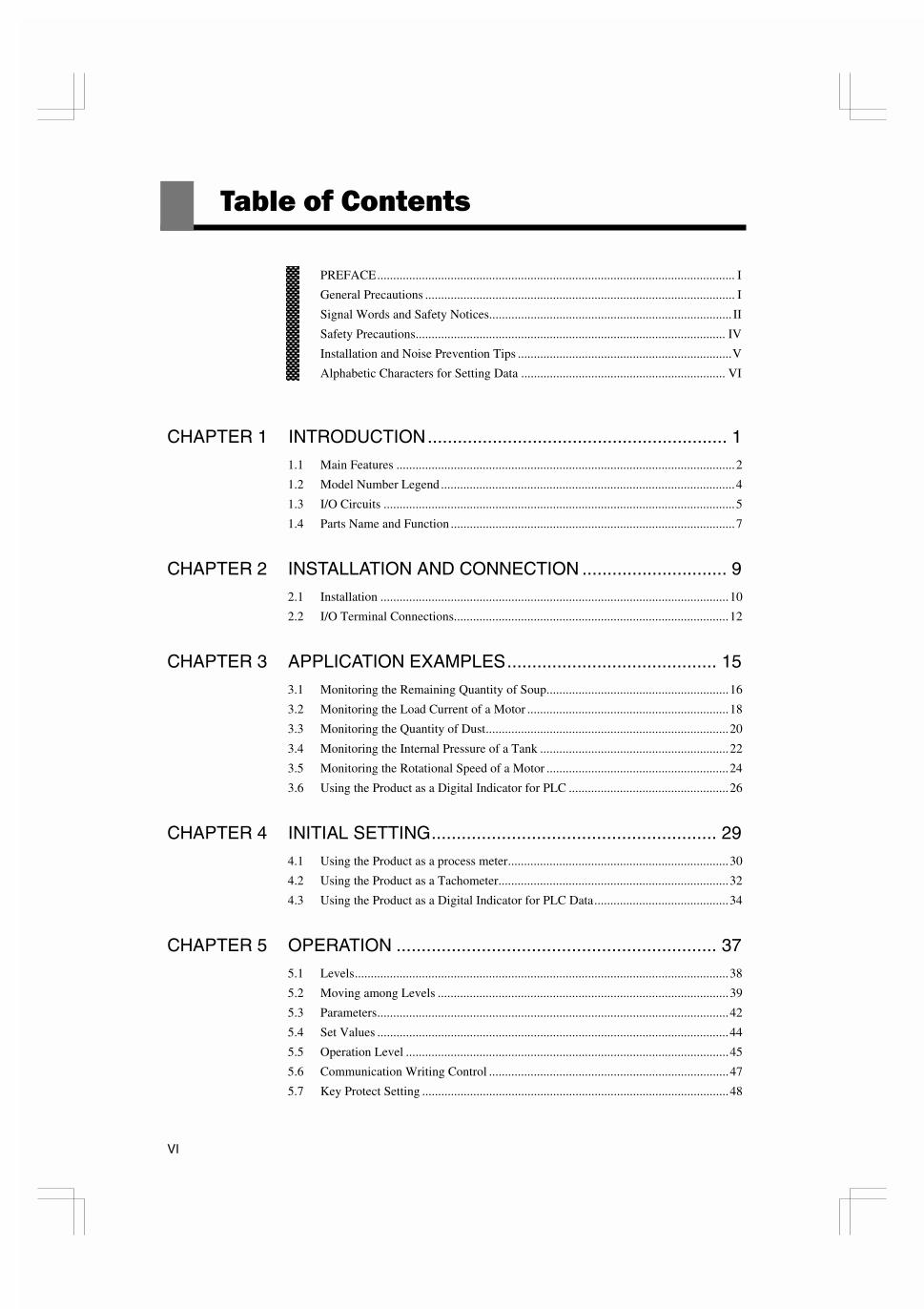
PREFACE................................................................................................................ I
General Precautions ................................................................................................. I
Signal Words and Safety Notices............................................................................ II
Safety Precautions................................................................................................. IV
Installation and Noise Prevention Tips ...................................................................V
Alphabetic Characters for Setting Data ................................................................ VI
CHAPTER 1 INTRODUCTION............................................................ 1
1.1 Main Features ..........................................................................................................2
1.2 Model Number Legend ............................................................................................4
1.3 I/O Circuits ..............................................................................................................5
1.4 Parts Name and Function .........................................................................................7
CHAPTER 2 INSTALLATION AND CONNECTION ............................. 9
2.1 Installation .............................................................................................................10
2.2 I/O Terminal Connections......................................................................................12
CHAPTER 3 APPLICATION EXAMPLES.......................................... 15
3.1 Monitoring the Remaining Quantity of Soup.........................................................16
3.2 Monitoring the Load Current of a Motor ...............................................................18
3.3 Monitoring the Quantity of Dust............................................................................20
3.4 Monitoring the Internal Pressure of a Tank ...........................................................22
3.5 Monitoring the Rotational Speed of a Motor .........................................................24
3.6 Using the Product as a Digital Indicator for PLC ..................................................26
CHAPTER 4 INITIAL SETTING......................................................... 29
4.1 Using the Product as a process meter.....................................................................30
4.2 Using the Product as a Tachometer........................................................................32
4.3 Using the Product as a Digital Indicator for PLC Data..........................................34
CHAPTER 5 OPERATION ................................................................ 37
5.1 Levels.....................................................................................................................38
5.2 Moving among Levels ...........................................................................................39
5.3 Parameters..............................................................................................................42
5.4 Set Values ..............................................................................................................44
5.5 Operation Level .....................................................................................................45
5.6 Communication Writing Control ...........................................................................47
5.7 Key Protect Setting ................................................................................................48

VII
5.8 Selecting an Input Type......................................................................................... 50
5.9 Selecting an Analog Range ................................................................................... 51
5.10 Selecting an Input-pulse Frequency Range ........................................................... 52
5.11 Specifying the Scaling Factor for Analog Input/Digital Data Display .................. 53
5.12 Specifying the Scaling Factor for Input Pulse Frequency ..................................... 55
5.13 Specifying the Decimal Point Position.................................................................. 58
5.14 Selecting the Output Operating Action ................................................................. 59
5.15 Specifying Communication Parameters ................................................................ 60
5.16 Clearing All Parameters ........................................................................................ 62
5.17 Specifying the Number of Measurements for Averaging...................................... 63
5.18 Specifying the Function of the Event Input........................................................... 64
5.19 Specifying the Hysteresis ...................................................................................... 66
5.20 Specifying the Auto-zero Time ............................................................................. 68
5.21 Specifying the Startup Compensation Time.......................................................... 70
5.22 Changing the Display Color .................................................................................. 72
5.23 Changing the Display Auto-return Time ............................................................... 74
5.24 Changing the Move-to-Protect-Level Time .......................................................... 76
5.25 Changing the Send Waiting Time ......................................................................... 78
CHAPTER 6 FUNCTION DESCRIPTION.......................................... 81
6.1 Measurement ......................................................................................................... 82
6.2 Scaling................................................................................................................... 84
6.3 Auto-zero/Startup Compensation .......................................................................... 86
6.4 Average Processing ............................................................................................... 87
6.5 Event Input/Pulse Input ......................................................................................... 88
6.6 Process Value Hold ............................................................................................... 89
6.7 Forced-zero............................................................................................................ 90
6.8 Comparative Output .............................................................................................. 91
6.9 Hysteresis .............................................................................................................. 92
6.10 Display Color Change ........................................................................................... 93
CHAPTER 7 COMMUNICATIONS .................................................... 95
7.1 Communication Protocols ..................................................................................... 96
7.2 Data Format Structure ........................................................................................... 97
7.3 Structure of Command/Response Text.................................................................. 99
7.4 Variable Area ...................................................................................................... 100
7.5 Read from Variable Area .................................................................................... 101
7.6 Write to Variable Area ....................................................................................... 102
7.7 Operation Instructions ......................................................................................... 103
7.8 Setting Areas ....................................................................................................... 104
7.9 Commands and Responses .................................................................................. 105
7.10 Variable Area Map .............................................................................................. 113
7.11 Communications Control Flow ........................................................................... 116
7.12 Programming Example........................................................................................ 121
VIII
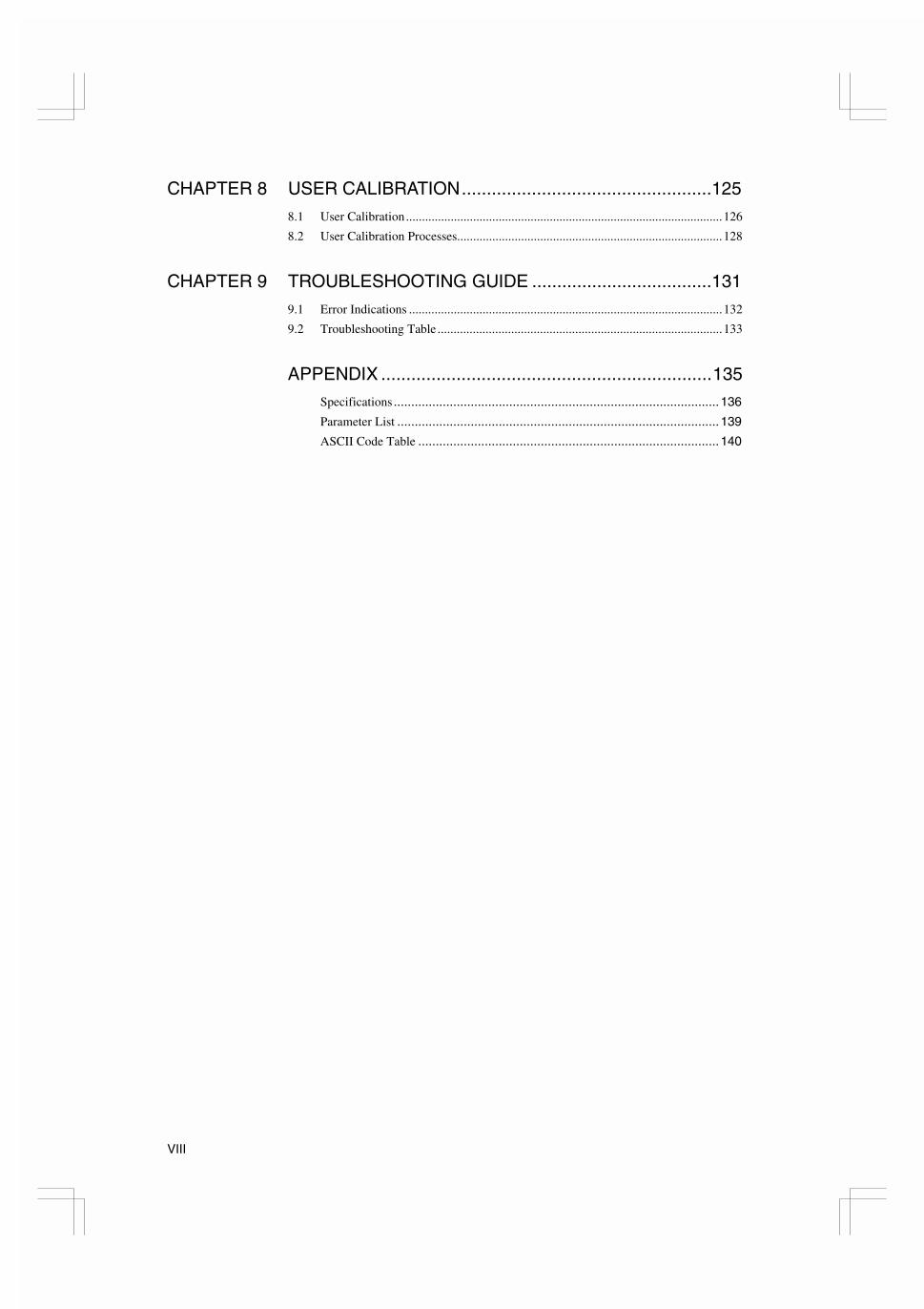
CHAPTER 8 USER CALIBRATION..................................................125
8.1 User Calibration...................................................................................................126
8.2 User Calibration Processes...................................................................................128
CHAPTER 9 TROUBLESHOOTING GUIDE ....................................131
9.1 Error Indications ..................................................................................................132
9.2 Troubleshooting Table .........................................................................................133
APPENDIX ..................................................................135
Specifications .............................................................................................136
Parameter List ............................................................................................139
ASCII Code Table ......................................................................................140
1.1 Main Features
1
,1752'8&7,21
% �����&������
1.1 Main FeaturesCCCCCCCCCCCCCCCCCCCCCCCCCCCCCCCCCCCCCCCCCCCCCC2
1.2 Model Number Legend CCCCCCCCCCCCCCCCCCCCCCCCCCCCCCCCCCCCC4
1.3 I/O Circuits CCCCCCCCCCCCCCCCCCCCCCCCCCCCCCCCCCCCCCCCCCCCCCCC5Input Circuit Diagrams/Output Circuit Diagrams/
Internal Block Diagram
1.4 Parts Name and Function CCCCCCCCCCCCCCCCCCCCCCCCCCCCCCCCCCC7
This chapter provides an overview of the product.
�'�����

CHAPTER 1 INTRODUCTION
2
,1752'8&7,21
��������������
The K3GN is a digital panel meter that is capable of converting an input signalinto a digital value and displaying it on the main indicator.
The main futures of the product include the following.
This feature measures an input signal and displays it as a digital value.
An analog value (voltage/current), a rotational speed (pulses), or digital datareceived via communication function can be selected as an input signal.
This feature converts an input signal into adesired physical value
The figure on the right shows a scaling examplewhere input signals from a pressure sensorranging from 4 to 20 mA are converted intovalues ranging from 0 to 100 (kPa). Scaling willenable you to handle physical quantities easilyand intuitively.
This feature compares a scaled (process) value with a programmed OUT set valueand produces output according to the comparison result.
This is useful in monitoring various systems for malfunction or determiningwhether products are within acceptance limits.
Three types of comparative outputs are available: those produced at the OUTupper-limit value, the OUT lower-limit value, and both the OUT values.
(�����)��
��)#���� �
���#��
������
�=(52
������
T
����� K3GN
287�
287�
69
=(52
+2/'
&0:
PLCPC
Voltage/current
ON/OFF
RS485
�=(52
������
T
����� K3GN
287�
287�
69
=(52
+2/'
&0:
4mA 20mA
100kPa
0kPaInput
Readout
Comparative outputproduced at the OUT lower
limit value
Comparative output produced atthe OUT upper and lower limit
values
OUT upperlimit value
Comparative output
Comparative outputproduced at the OUT upper
limit value
OUT lowerlimit value
OUT upperlimit value
OUTlowerlimit
value
Comparative output Comparative output

1.1 Main Features
3
,1752'8&7,21
This feature enables a process valueto be held while the external eventinput stays ON.
The outputs are also retained.
This feature shifts a process value to zero, and can be used to evaluate and displaythe deviation of a process value from a reference value.
The forced-zero function can be activated by using the 4 key on the front panel,via the event input terminal, or communications.
This feature allows programming of the display color. In the example shownbelow, the display color is programmed so that it changes from green to red whena comparative output turns ON. The display color can also be programmed so thatit changes red to green or is fixed to red or green.
This feature allows the host PC to read process values from the product orread/write various parameter settings from/to the host PC.
The host PC provides logging of measured data and remote control to the product.
��))��*
�����
������
+���� '���
�����*,��
����������
�� ��
������
T
������
T
������
T
485 232C
Processvalue
HOLD input
Processvalue
ZERO input
Forced-zero value(shifted value)
Measurement valueafter executing theforced-zero function
������
T
OUT2 value
OUT1 value ������
T
����
T
Green
Red
Red
CHAPTER 1 INTRODUCTION
4
,1752'8&7,21
��������������������
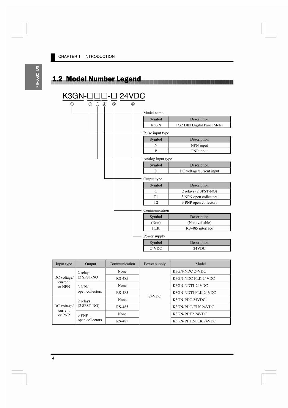
K3GN-���-� 24VDC� � � � � �
Model name
Symbol Description
K3GN 1/32 DIN Digital Panel Meter
Pulse input type
Symbol Description
N NPN input
P PNP input
Analog input type
Symbol Description
D DC voltage/current input
Output type
Symbol Description
C 2 relays (2 SPST-NO)
T1 3 NPN open collectors
T2 3 PNP open collectors
Communication
Symbol Description
(Non) (Not available)
FLK RS-485 interface
Power supply
Symbol Description
24VDC 24VDC
Input type Output Communication Power supply Model
None K3GN-NDC 24VDC2 relays(2 SPST-NO) RS-485 K3GN-NDC-FLK 24VDC
None K3GN-NDT1 24VDC
DC voltage/currentor NPN 3 NPN
open collectors RS-485 K3GN-NDTI-FLK 24VDC
None K3GN-PDC 24VDC2 relays(2 SPST-NO) RS-485 K3GN-PDC-FLK 24VDC
None K3GN-PDT2 24VDC
DC voltage/currentor PNP 3 PNP
open collectors RS-485
24VDC
K3GN-PDT2-FLK 24VDC

1.3 I/O Circuits
5
,1752'8&7,21
���������������
�#�� ������ &����)�
� ����� �#��
� � �� �#��-����� �#��
���#�� ������ &����)�
� ������ ���#��
Voltage input Current input
NPN input PNP input
12
11
9
COM
OUT2
OUT15V
5V
1
3
2
2.35K:
4.7K:
24VDC-
HOLD/ZEROPulse
24VDC+ 1
3
2
2.35K:
4.7K:
24VDC-
24VDC+
HOLD/ZEROPulse
-
+A
B
ADVoltage
COM
4
5
-
+
60:
ADCurrent
COM
6
5A+B = 1M:
To To

CHAPTER 1 INTRODUCTION
6
,1752'8&7,21
� ������� ���#��
����� .���/ &����)
NPN output PNP output
Microcomputer
Drive circuit
Key Display
ADconvertor
Input circuit
EEPROM
Communi-cationdriver
Waveformrecitification
circuit
Constant-voltagecircuit 1
Controlinputcircuit
Drive circuit
Drive circuitOutputcircuit
Constant-voltagecircuit 2
Power supplycircuit
Operationpower supply
Event input/pulse input
terminal
Communi-cation
terminal
Contactoutput
Transistoroutput
Analog inputterminal
*1
*2
*3
*1 Available only for the product with transistor output
*2 Available only for the product with relay output
*3 Available only for the product with communication interface
11
12
10
9
COM
OUT2
PASS
OUT1
8.2:
8.2:
8.2:
8.2:
11
12
10
9
COM
OUT2
PASS
OUT1
8.2:
8.2:
1.4 Parts Name and Function
7
,1752'8&7,21
�������� ����������������
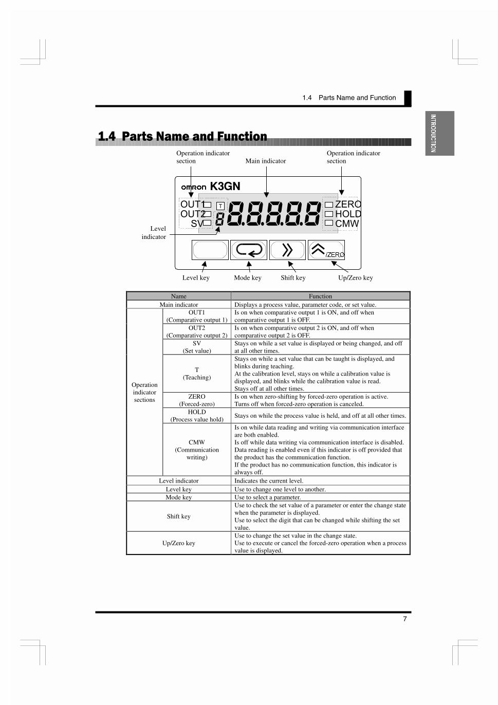
Name FunctionMain indicator Displays a process value, parameter code, or set value.
OUT1(Comparative output 1)
Is on when comparative output 1 is ON, and off whencomparative output 1 is OFF.
OUT2(Comparative output 2)
Is on when comparative output 2 is ON, and off whencomparative output 2 is OFF.
SV(Set value)
Stays on while a set value is displayed or being changed, and offat all other times.
T(Teaching)
Stays on while a set value that can be taught is displayed, andblinks during teaching.At the calibration level, stays on while a calibration value isdisplayed, and blinks while the calibration value is read.Stays off at all other times.
ZERO(Forced-zero)
Is on when zero-shifting by forced-zero operation is active.Turns off when forced-zero operation is canceled.
HOLD(Process value hold)
Stays on while the process value is held, and off at all other times.
Operationindicatorsections
CMW(Communication
writing)
Is on while data reading and writing via communication interfaceare both enabled.Is off while data writing via communication interface is disabled.Data reading is enabled even if this indicator is off provided thatthe product has the communication function.If the product has no communication function, this indicator isalways off.
Level indicator Indicates the current level.Level key Use to change one level to another.Mode key Use to select a parameter.
Shift key
Use to check the set value of a parameter or enter the change statewhen the parameter is displayed.Use to select the digit that can be changed while shifting the setvalue.
Up/Zero keyUse to change the set value in the change state.Use to execute or cancel the forced-zero operation when a processvalue is displayed.
�=(52
������
T
����� ����
����
����
��
��
���
���
Level key Mode key Shift key Up/Zero key
Operation indicatorsection
Levelindicator
Main indicatorOperation indicatorsection

1.4 Parts Name and Function
9
,167$//$7,21
$1'&211(&7,21
0 �����11�����
��& ����������
2.1 Installation CCCCCCCCCCCCCCCCCCCCCCCCCCCCCCCCCCCCCCCCCCCCCCCC10Dimensions/Panel Cutout Dimensions/
Installation Procedure
2.2 I/O Terminal Connections CCCCCCCCCCCCCCCCCCCCCCCCCCCCCCCCCC12Terminal Arrangement/Terminal Connection
This chapter describes how to install and connect the productbefore turning the power on.
�'�����

CHAPTER 2 Installation and Connection
10
,167$//$7,21
$1'&211(&7,21
������� �������
&�)�����
���� ������ &�)�����
Fit the product into a rectangular panel cutout, put the adapter on the product fromthe rear end all the way to the panel, and tighten the screws of the adapter tosecure the product.
When gang-mounting the products, make sure the ambient temperature of theproduct falls within the specified limits.
Separate mounting (units in mm) Gang mounting (units in mm)
3
2435
48
(36.
8)
80
2244
.8
Units in mm
� 7mm
3.6mm
Size of characters displayedon the main indicator
45 +0.6 -0
22.2
+0.
3 -
0
40 m
in.
60 min. (48 x No. of products -2.5) +1.0 -0
22.2
+0.
3 -
0
The products cannot be made waterproofwhen gang-mounted.
2.1 Installation
11
,167$//$7,21
$1'&211(&7,21
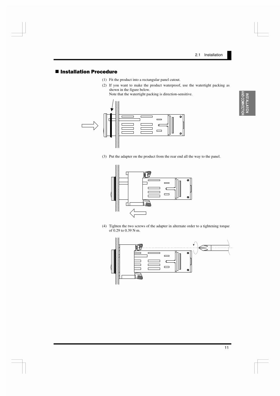
���������� �������(1) Fit the product into a rectangular panel cutout.
(2) If you want to make the product waterproof, use the watertight packing asshown in the figure below.Note that the watertight packing is direction-sensitive.
(3) Put the adapter on the product from the rear end all the way to the panel.
(4) Tighten the two screws of the adapter in alternate order to a tightening torqueof 0.29 to 0.39 N·m.

CHAPTER 2 Installation and Connection
12
,167$//$7,21
$1'&211(&7,21
�������������������������
��)��� ����)��
TerminalNo.
Name Description Applicable model
c-d Operationpower supply
Operation power supply terminals All models
e-d
Event inputor
pulse contact/input
Depending on parameter setting:x Hold the process value.x Serve as input terminals for the forced-
zero or forced-zero cancel operation.x Serve as pulse input terminals when the
input type is set to "pulse".
K3GN-ND_-_ 24VDC
e-c K3GN-PD_-_ 24VDCfh-g Analog input Voltage/current analog terminals All modelsi-j Communication RS-485 communication terminals K3GN-_D_-FLK 24VDCk 11 -12 Provide comparative output. K3GN-_DC-_ 24VDC
kl 11 -12
Comparativeoutput
Provide PASS output in addition toOUT1/OUT2 (comparative output 1/2)when the product is of transistor outputtype.
K3GN-NDT1-_ 24VDCK3GN-PDT2-_ 24VDC
��)��� �������
Wire the terminals using M3 crimp contacts of the type shown below.
5.8 mm max.
5.8 mm max.
9 10 11 12
OUT1 OUT2 COMPASS
9 10 11 12OUT1 OUT2 COMPASS
1 2 3A
NPNinput
PNPinput
1 2 3
Control voltage24VDC
Event input orpulse input
4 5 6
Voltage Current
Analog input
COMB Analoginput
C
Withoutcommunication
function
Withcommunication
function7 8
B (+) A (-)
RS485
7 8NC NC
D
Relayoutput
NPNtran-sistoroutput
PNPtran-sistoroutput
9 10 11 12OUT1 OUT2 COMNC
7 8 9 10 11 12
1 2 3 4 5 6A B
C D
Controlvoltage24VDC
Event input orpulse input

2.2 I/O Terminal Connections
13
,167$//$7,21
$1'&211(&7,21
� ��"� ��##��
Connect the following power supply to terminals c and d.Supply voltage: 24VDC
Operating voltage range: 85 to 110% of the rated voltagePower consumption: 2.5W (at max. load)
Note that, when turned on, the product will require the operation power supply tohave more power supply capacity than rated.If multiple products are used, the power supply must be able to afford to supplypower to the products.
� � �� �#�� � ����� �#��
Apply the event or pulse signal to terminals e and d if the product is of NPNinput type, or terminals e and c if the product is of PNP input type.
The input equipment connected to these terminals must meet the followingconditions.
Transistor output ON residual current: 2.5V max.
OFF leakage current: 0.1 mA max.
Current leakage withtransistor turned ON: 15 mA min.
Relay output Load current: 5 mA max.
� ����� �#��
The following table shows the analog ranges and applicable analog inputterminals.
Analog range Positive side Negative side4 to 20 mA/0 to 20 mA h g
1 to 5V/0 to 5V f g
±5V f g
±10V f g
The maximum absolute ratings for analog input are as follows.
Be careful that these ratings must not be exceeded even for a moment.
4 to 20 mA/0 to 20 mA: ±30 mA
1 to 5V/0 to 5V: ±13.5V
±5V: ±13.5V
±10V: ±26V
7 8 9 10 11 12
1 2 3 4 5 6
NPN input type PNP input type
1 2 3
Control power24VDC
Event orpulse input
1 2 3
Control power24VDC
Event orpulse input
7 8 9 10 11 12
1 2 3 4 5 6
7 8 9 10 11 12
1 2 3 4 5 6
NPN input
PNP input
7 8 9 10 11 12
1 2 3 4 5 6
7 8 9 10 11 12
1 2 3 4 5 6
Voltage input
Current input

CHAPTER 2 Installation and Connection
14
,167$//$7,21
$1'&211(&7,21
� ��))�������
Connect the communication cable to terminals i and j if using thecommunication function.
RS-485 connections can be one-to-one or one-to N. A maximum of 32 units(including the host computer) can be connected in one-to-N systems.
The total length of the communication cables should be up to 500 m.
Use shielded twisted-pair cables (AWG 28 or thicker) as the communicationcables.
Be sure to turn ON the terminator switches only in the devices at each end of thetransmission line.
Match the communications format of the K3GN and the host computer. If a one-to-N system is being used, be sure that the communications formats of all devicesin the system (except individual unit numbers) are the same.
Chapter 7 explains how to set the K3GN communication format. Refer to yourcomputer's manual for details on changing its communications settings.
� ��)#���� � ���#��
Comparative output is produced at terminals k to 12 .
If the product is of relay output type, terminal l is not used.
Loads connected to the product and the power supply for the loads must be ratedas follows.
The connection causes the current to flow in the direction opposite to
indicated by the arrows.
7 8 9 10 11 12
1 2 3 4 5 6
7 8 9 10 11 12
1 2 3 4 5 6
Transistor output
7 8 9 10 11 12
1 2 3 4 5 6
Relay output
OUT1 OUT2 COMNC
9 10 11 12
Load
Load
1A max
.
OUT1 OUT2 COMPASS
9 10 11 12
£Æ¸»
£Æ¸»
£Æ¸»
PNP
30V
DC
max
.
1A max
.
24V
DC
max
.
50 m
Am
ax.
50 m
Am
ax.
50 m
Am
ax.
Relay output type Transistor output type
7 8
(B) (A)
7 8
(B) (A)
7 8
(B) (A)
Terminator120: (1/2:)
K3GN(No. 1)
K3GN(No. 2)
K3GN(No. 31)
+ -
RS232C-RS485interface convertor
RS232C
Terminator120: (1/2:)

2.2 I/O Terminal Connections
15
$33/,&$7,21
(;$03/(6
2 ���1�������
�3�(�1��
3.1 Monitoring the Remaining Quantity of SoupCCCCCCCCCCCCCCCCCC16
3.2 Monitoring the Load Current of a Motor CCCCCCCCCCCCCCCCCCCCC18
3.3 Monitoring the Quantity of DustCCCCCCCCCCCCCCCCCCCCCCCCCCCCC20
3.4 Monitoring the Internal Pressure of a Tank CCCCCCCCCCCCCCCCCCC22
3.5 Monitoring the Rotational Speed of a Motor CCCCCCCCCCCCCCCCCC24
3.6 Using the Product as a Digital Indicator for PLC CCCCCCCCCCCCCC26
This chapter shows some examples of product applications.
�'�����

CHAPTER 3 APPLICATION EXAMPLES
16
$33/,&$7,21
(;$03/(6
��������������� �!��������"����#��$�%��&
x The remaining quantity of soup is monitored.
x The soup level is measured with an ultrasonic displacement sensor.
x The K3GN indicates the remaining quantity of soup on a percentage basis.
x Four measurements are averaged for stable indication.
x Comparative output 1 is produced as a lower-limit action signal. When theremaining quantity of soup reaches 20% (lower limit), the “Replenish” indicatorturns on.
���������
���� �
7 8 9 10 11 12
1 2 3 4 5 6
4 to 20mACurrent
inputCOM
Operationpower supply
24VDC
K3GN-NDC
Black
Ultrasonic displacementsensor
Brown (+)
Blue (-)
COM
Comparative output 1
K3GN-NDC
Cup (L)
5HPDLQLQJTXDQWLW\ RI VRXS
Cup (M)
Cup (S)
20%
100%
5HSOHQLVK
4 to 20mA
Comparative output 1(lower-limit action)
Ultrasonic sensor
500m
m
60m
m
60mm ~ 500mm
3.1 Monitoring the Remaining Quantity of Soup
17
$33/,&$7,21
(;$03/(6
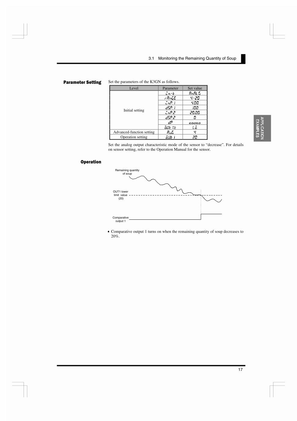
Set the parameters of the K3GN as follows.
Level Parameter Set value
@E�K 8E8C>
I8E>< ����
@EG�� ����
;JG�� ���
@EG�� �����
;JG�� �
;G �����
Initial setting
FLK��K CF
Advanced-function setting 8M> �
Operation setting FLK� ��
Set the analog output characteristic mode of the sensor to “decrease”. For detailson sensor setting, refer to the Operation Manual for the sensor.
x Comparative output 1 turns on when the remaining quantity of soup decreases to20%.
��������������� �
�������
Remaining quantityof soup
OUT1 lowerlimit value
(20)
Comparativeoutput 1

CHAPTER 3 APPLICATION EXAMPLES
18
$33/,&$7,21
(;$03/(6
��������������� �������������$�������
x The load current of a motor is monitored.
x A 10:1 current transformer is used to detect the motor current.
x The current transformer K3FK-CE-1A-R is used to adapt the input current to aK3GN analog range.
x The K3GN indicates the load current in units of amperage to two decimal places.
x Comparative output 1 is used to generate an upper-limit action signal andcomparative output 2 is used to generate a lower-limit action signal.
x The OUT upper-limit value is set to 6.00A and the OUT lower-limit value is setto 3.00A.
���������
���� �
7 8 9 10 11 12
1 2 3 4 5 6
7
8
1
2
Line side
Load side
K
L
l
k3
4
Current protectorK3FK-CTM
K3FK-CE-1A-R
Signaloutput
+
-
Current input
COM
Operationpowersupply
24VDC
+
-
K3GN-NDC
COM
Comparativeoutput 1
Comparativeoutput 2
Power supply
Signal input
Electro-magnetic
relay
24VDCpower supply
Comparativeoutput 1
(upper-limit action)
Comparativeoutput 2
(lower-limit action)Current transformerK3FK-CE-1A-R K3GN-NDC
0 to 10A AC 10:1 currenttransformer
0 to 1A 4 to 20mA�=(52
������
T
����� K3GN
287�
287�
69
=(52
+2/'
&0:
3.2 Monitoring the Load Current of a Motor
19
$33/,&$7,21
(;$03/(6
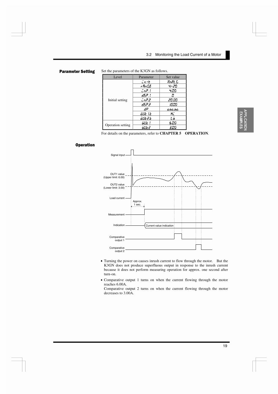
Set the parameters of the K3GN as follows.
Level Parameter Set value
@E�K 8E8C>
I8E>< ����
@EG�� ����
;JG�� �
@EG�� �����
;JG�� ����
;G ������
FLK��K ?@
Initial setting
FLK��K CF
FLK� ����Operation settingFLK� ����
For details on the parameters, refer to CHAPTER 5 OPERATION.
x Turning the power on causes inrush current to flow through the motor. But theK3GN does not produce superfluous output in response to the inrush currentbecause it does not perform measuring operation for approx. one second afterturn-on.
x Comparative output 1 turns on when the current flowing through the motorreaches 6.00A.Comparative output 2 turns on when the current flowing through the motordecreases to 3.00A.
��������������� �
�������
Signal input
Load current
OUT1 value(Upper limit: 6.00)
OUT2 value(Lower limit: 3.00)
Measurement
Indication Current value indication
Approx.1 sec.
Comparativeoutput 1
Comparativeoutput 2

CHAPTER 3 APPLICATION EXAMPLES
20
$33/,&$7,21
(;$03/(6
��������������� �"����#��$�'�
x The quantity of dust exhausted from a dust collector into the air is monitored.
x The analog photoelectric sensor E3SA is used to detect the quantity of dust.
x A dust quantity of 0 to 1500 ppm corresponds to an E3SA output of 4 to 20 mA.
x The K3GN indicates the quantity of dust in units of ppm.
x Comparative output 1 is used to generate an upper-limit action signal thatreduces the crusher power.
x Comparative output 2 is used to generate another upper-limit action signal thatstops the crusher.
x The OUT 1 upper-limit value is 800 ppm and the OUT2 upper-limit value is1000 ppm.
x Eight measurements are averaged for stable indication.
x The hysteresis is set to 10 for stable output in the vicinity of the OUT set values.
���������
���� �
7 8 9 10 11 12
1 2 3 4 5 6
4 to 20mA Currentinput
COM
Operationpower supply
24VDC
K3GN-NDC
COM
Comparativeoutput 1
Comparativeoutput 2
Stripes of orange/purple
Brown (+)
Blue (-)
Black
Analog photoelectricsensor E3SA
To the air
Dust collector
Crusher
0 to 1500ppm
Comparative output 1(upper-limit action)
K3GN-NDC
4 to 20mA
Analog photoelectricsensor E3SA
Crusher powerreduction command
Comparative output 2(upper-limit action)
Crusher stop command
�=(52
������
T
����� K3GN
287�
287�
69
=(52
+2/'
&0:

3.3 Monitoring the Quantity of Dust
21
$33/,&$7,21
(;$03/(6
Set the parameters of the K3GN as follows.
Level Parameter Set value
@E�K 8E8C>
I8E>< ����
@EG�� ����
;JG�� �
@EG�� �����
;JG�� ����
;G �����
FLK��K ?@
Initial setting
FLK��K ?@
8M> �
?PJ� ��Advanced-function setting
?PJ� ��
FLK� ���Operation settingFLK� ����
For details on the parameters, refer to CHAPTER 5 OPERATION.
x Comparative output 1 turns on when the dust quantity reaches 800 ppm.
x When comparative output 1 turns on, the crusher power is reduced until the dustquantity decreases to within the specified range.
x Comparative output 2 turns on when an accident causes a sudden increase indust quantity to 1000 ppm.
x When comparative output 2 turns on, it provides an emergency stop to thecrusher.
��������������� �
�������
Dust quantity
OUT1 value(Upper limit: 800)
OUT2 value(Upper limit: 1000)
Comparativeoutput 1
Comparativeoutput 2
Hysteresis

CHAPTER 3 APPLICATION EXAMPLES
22
$33/,&$7,21
(;$03/(6
��������������� ���������� ����$������(
x The internal pressure of a tank is monitored.
x The pressure sensor E8AA-M10 is used to detect the pressure in the tank.
x A pressure of 0 to 980 kPa corresponds to an E8AA-M10 output of 4 to 20 mA.
x The K3GN indicates the pressure in units of kPa to one decimal place.
x The communication function of the K3GN enables remote monitoring of thepressure on the host PC.
x The status of comparative outputs is read by the host PC at a remote site.
x Comparative output 1 turns on when the pressure reaches 550.0 kPa, whichgenerates an upper-limit action signal.
x Comparative output 2 turns on when the pressure decreases to 100.0 kPa, whichgenerates a lower-limit action signal.
���������
���� �
7 8 9 10 11 12
1 2 3 4 5 6
4 to 20mA Currentinput
COM
Operationpower supply
24VDC
K3GN-NDC-FLK
Black
Pressure sensorE8AA-M10
Brown (+)
Blue (-)
B(+) A(-)
To host PCvia RS-485
K3GN-NDC-FLK
4 to 20mA
Pressure sensorE8AA-M10
Tank
0 to 980kPa
RS485 RS232C
Host PC
�=(52
������
T
����� K3GN
287�
287�
69
=(52
+2/'
&0:

3.4 Monitoring the Internal Pressure of a Tank
23
$33/,&$7,21
(;$03/(6
Set the parameters of the K3GN as follows.
Level Parameter Set value
@E�K 8E8C>
I8E>< ����
@EG�� ����
;JG�� �
@EG�� �����
;JG�� ����
;G ������
FLK��K ?@
Initial setting
FLK��K CF
L�EF �
9GJ ���
C<E �
J9@K �
Communicationsetting
GIKP <M<E
FLK� �����Operation settingFLK� �����
Set the communication parameters according to the host PC setting.
For details on the parameters, refer to CHAPTER 5 OPERATION.
x The host PC reads the current value and the status from the K3GN at regularintervals.
Of command and response frames, only text fields are shown in the above figure.
For details on communications, refer to CHAPTER 7 COMMUNICATIONS.
��������������� �
�������
Tank pressure
OUT1 value(Upper limit: 550.0)
OUT2 value(Lower limit: 100.0)
Command 1
534.2kPa
568.8kPa
Response 1
Command 2
Response 2
"000014DE"
MRC
"01"
SRC
"01"
Variabletype
"C0" "0001"
Address Bit position
"00" "0002"
No. of elements
MRC
"01"
SRC
"01" "0000"
Response code Current value
Command 1
Response 1 "00000400"
Status
14DEH (5342 in decimal) (PASS output ON)
"00001638"
MRC
"01"
SRC
"01"
Variabletype
"C0" "0001"
Address Bit position
"00" "0002"
No. of elements
MRC
"01"
SRC
"01" "0000"
Response code Current value
Command 2
Response 2 "00000100"
Status
1638H (5688 in decimal) (Comparative output 1 ON)

CHAPTER 3 APPLICATION EXAMPLES
24
$33/,&$7,21
(;$03/(6
��)������������ �!��������%&���$�������
x In addition to the load current monitored in the application shown in Section 3.2,the rotational speed of a motor is also monitored with an additional K3GN.
x A four-toothed wheel is installed on the motor shaft to allow detection of itsrotational speed.
x The proximity sensor E2E-X1R5E1 converts motor shaft rotations to on/offpulses.
x The K3GN indicates the rotational speed in terms of rpm.
x A startup compensation timer is used to prevent superfluous output from beingproduced until the motor reaches a designated speed (for five seconds afterstartup).
x Comparative output 1 is used to generate an upper-limit action signal.Comparative output 2 is used to generate a lower-limit action signal.
x The OUT1 upper-limit value is set to 3500 rpm and the OUT2 lower-limit valueto 1000 rpm.
x The auto-zero function is used to enhance the lower-limit response.(A speed of 150 rpm or less is automatically shifted to zero).
���������
���� �
7 8 9 10 11 12
1 2 3 4 5 6
Proximity sensorE2E-X1R5E1
Pulse input
Operationpower supply
24VDC
Brown (+)
K3GN-NDC
COM
Comparativeoutput 1
Comparativeoutput 2
Blue (-)
Black
Power supply
Signal input
Electro-magnetic
relay
24VDC power supply
Comparativeoutput 1
(upper-limit action)
Comparativeoutput 2
(lower-limit action)Current transformerK3FK-CE-1A-R K3GN-NDC
0 to 10A ACCurrenttransformer10:1
0 to 1A 4 to 20mA
¢��¥�¥��
Proximity sensorE2E-X1R5E1
Comparativeoutput 1
(upper-limit action)
Comparativeoutput 2
(lower-limit action)
�=(52
������
T
����� K3GN
287�
287�
69
=(52
+2/'
&0:
�=(52
������
T
����� K3GN
287�
287�
69
=(52
+2/'
&0:

3.5 Monitoring the Rotational Speed of a Motor
25
$33/,&$7,21
(;$03/(6
Set the parameters of the K3GN as follows.
Level Parameter Set value
@E�K GLCJ<
G�=I< �B
@EG ����
;JG �����
;G �����
FLK��K ?@
Initial setting
FLK��K CF
8LKF�Q ���Advanced-function settingJ�KDI ���
FLK� ����Operation settingFLK� ����
For details on the parameters, refer to CHAPTER 5 OPERATION.
x The startup compensation timer works for five seconds after the motor power isturned on. This prevents superfluous output from being produced by theK3GN.
x Comparative output 1 turns on when the motor speed reaches 3500 rpm.Comparative output 2 turns on when the motor speed decreases to 1000 rpm.
��������������� �
�������
Signal input
Motor speed
OUT1 value(Upper limit: 3500)
OUT 2 value(Lower limit: 1000)
Measurement
Indication Current value indication
5 sec.
Comparativeoutput 1
Comparativeoutput 2
CHAPTER 3 APPLICATION EXAMPLES
26
$33/,&$7,21
(;$03/(6
��*��+ ���� ��������� ���'���������������$������
x The K3GN is used as a digital indicator for PLC data.
x The display color of the K3GN main indicator is set to “always green”.
x The process value is displayed without scaling.
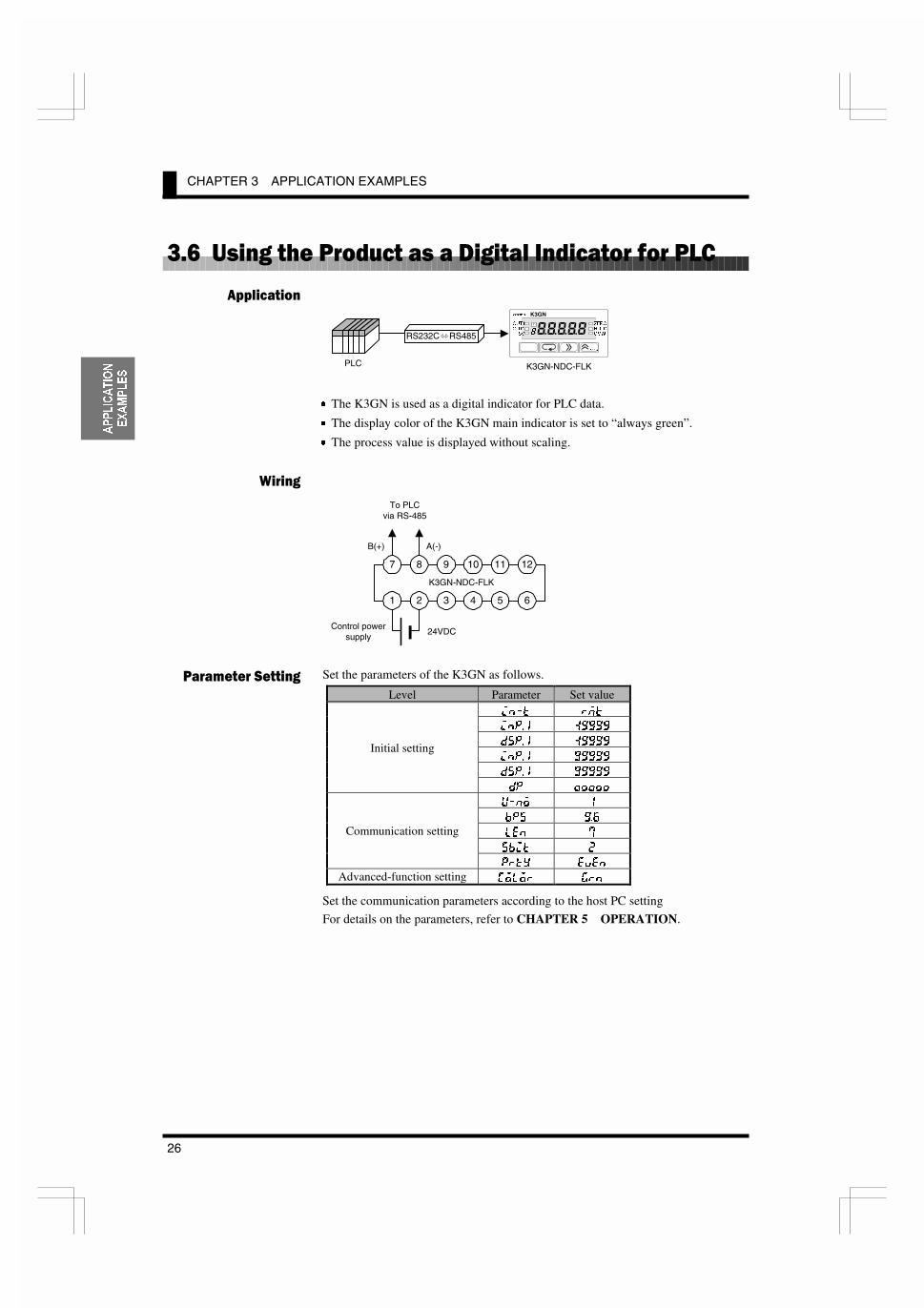
Set the parameters of the K3GN as follows.
Level Parameter Set value
@E�K IDK
@EG�� �����
;JG�� �����
@EG�� �����
;JG�� �����
Initial setting
;G �����
L�EF �
9GJ ���
C<E �
J9@K �
Communication setting
GIKP <M<E
Advanced-function setting :FCFI >IE
Set the communication parameters according to the host PC setting
For details on the parameters, refer to CHAPTER 5 OPERATION.
���������
���� �
��������������� �
7 8 9 10 11 12
1 2 3 4 5 6
Control powersupply
24VDC
K3GN-NDC-FLK
B(+) A(-)
To PLCvia RS-485
K3GN-NDC-FLK
RS232C RS485
PLC
�=(52
������
T
����� K3GN
287�
287�
69
=(52
+2/'
&0:
3.6 Using the Product as a Digital Indicator for PLC
27
$33/,&$7,21
(;$03/(6
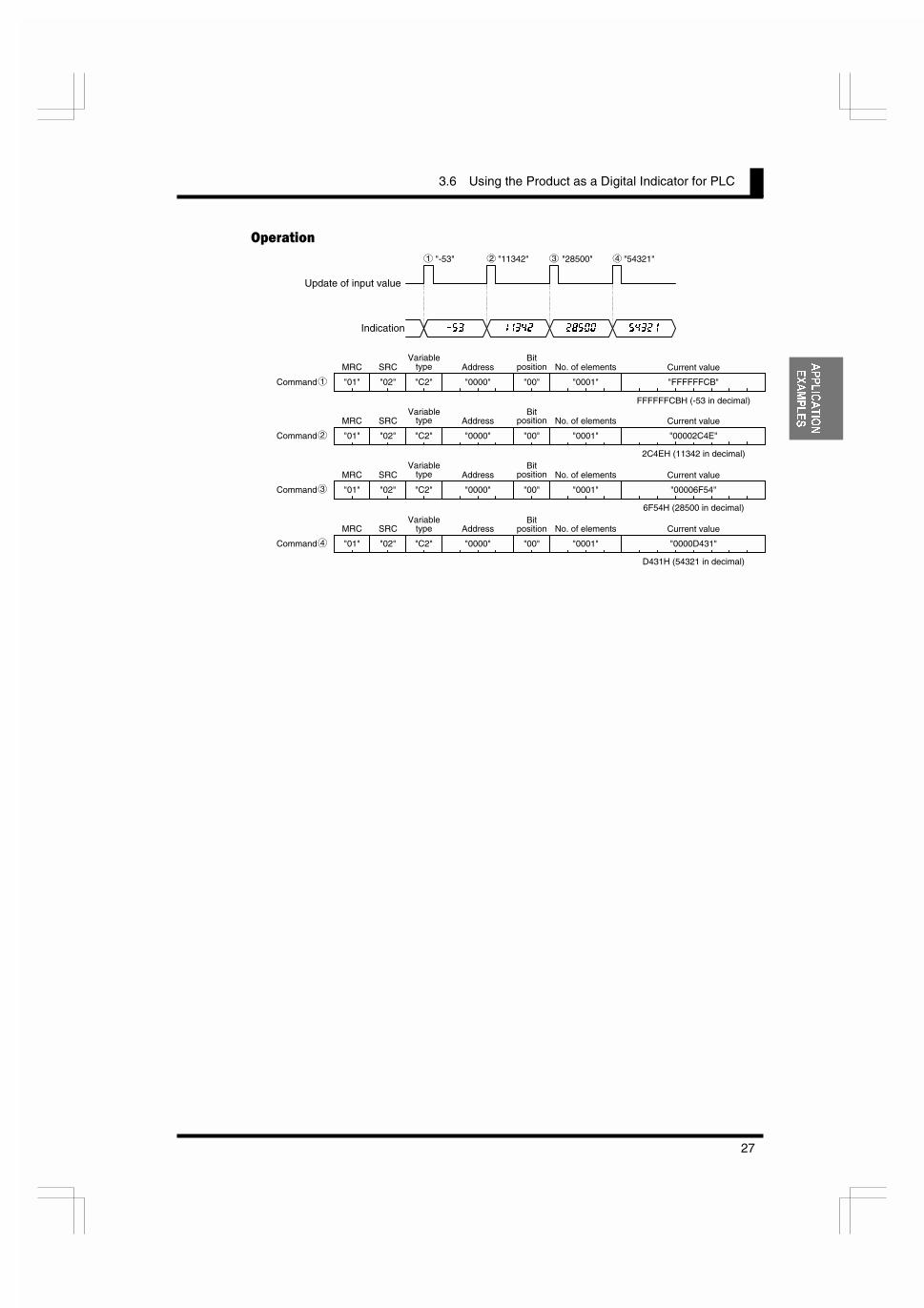
�������
Update of input value
Indication
MRC
"01"
SRC
"02" "C2" "0000"
Address
"00" "0001"
No. of elements
���
"-53" "11342" "28500" "54321"
����� ����� �����
"FFFFFFCB"
Current value
FFFFFFCBH (-53 in decimal)
Command
MRC
"01"
SRC
"02" "C2" "0000"
Address
"00" "0001"
No. of elements
"00002C4E"
Current value
2C4EH (11342 in decimal)
MRC
"01"
SRC
"02" "C2" "0000"
Address
"00" "0001"
No. of elements
"00006F54"
Current value
MRC
"01"
SRC
"02" "C2" "0000"
AddressBit
position
"00" "0001"
No. of elements
"0000D431"
Current value
6F54H (28500 in decimal)
D431H (54321 in decimal)
Command
Command
Command
Variabletype
Bitposition
Variabletype
Bitposition
Variabletype
Bitposition
Variabletype
1 2 3 4
1
2
3
4
3.6 Using the Product as a Digital Indicator for PLC
29
,1,7,$/
6(77,1*
4 ������1 �������
4.1 Using the Product as a process meterCCCCCCCCCCCCCCCCCCCCCCCCC30
4.2 Using the Product as a Tachometer CCCCCCCCCCCCCCCCCCCCCCCCCC32
4.3 Using the Product as a Digital Indicator CCCCCCCCCCCCCCCCCCCCCC34
Typical applications of the product include a process meter, atachometer, or an indicator of digital data from PLC/PC.
This chapter explains the flow of initial setting for each of theseapplications.
�'�����

CHAPTER 4 INITIAL SETTING
30
,1,7,$/
6(77,1*
�����+ ���� ��������� ���&��� ���
The following example shows the flow of initial setting for the product that is usedas a process meter.
Setting example:Input signals ranging from 1 to 5V is scaled to readouts ranging from 0 to100 kg.Comparative output 1 is produced when the process value (readout) reaches70.0 kg.Comparative output 2 is produced when the process value (readout)decreases to 50.0 kg.
�������������� ��
�$ Check wiring for correct connection and power the product on.
The product is factory set to have an analog input range of 4 to 20 mA.If an input that falls outside this default range is received, the mainindicator of the product will read “J�<II” and blink, indicating an“input range over” error occurs.
.$ Set “input type” to “analog”.
1. Make sure the main indicator displays a process value (the product isat the operation level).Then press the . key and hold it down for at least one second.The product will move to the initial setting level.
2. Set parameter “@E�K” to “8E8C>”.
�$ Set “analog range” to “1 ~ 5V”.
1. Set parameter “I8E><” to “���”.
&$ Specify the scaling factor.
1. Set parameter “@EG��” to “�����”.
2. Set parameter “;JG��” to “�”.
3. Set parameter “@EG��” to “�����”.
4. Set parameter “;JG��” to “����”.
�$ Specify the decimal point position.
1. Set parameter “;G” to “������”.
The input type, analog range,scaling factor, and decimalpoint position should be set inthis order.Otherwise, auto-initializationof parameters may result in afailure in parameter setting.If you specify the scalingfactor and then the input type,for example, the analogrange and the scaling factorare initialized automatically.
1RWH
Input signal1.000V 5.000V
100.0kg
0.0kg
Readout
Normalrange
Comparativeoutput 2
Comparativeoutput 1
50.0kg 70.0kg
4.1 Using the Product as a process meter
31
,1,7,$/
6(77,1*
�$ Set “OUT1 value type” to “upper limit” and “OUT2 value type” to “lowerlimit”.
1. Set parameter “FLK��K” to “?@”.
2. Set parameter “FLK��K” to “CF”.
�$ Set the OUT1 value to “70.0” and the OUT2 value to “50.0”.
1. Make sure the main indicator displays an initial setting level parameter(the product is at the initial setting level).Then press the . key and hold it down for at least one second.The product will move to the operation level.
2. Set parameter “FLK�” to “����”.
3. Set parameter “FLK�” to “����”.
'$ Bring the product into measuring operation.
For details on parameter setting, refer to CHAPTER 5 OPERATION.
The number ofmeasurements for averagingand the hysteresis can bechanged if required.These parameters are to beset at the advanced-functionsetting level.
If you are confused about how parameters have been set during initial setting,you can clear all the parameters and start all over again.
For details on how to clear all parameters, refer to Section 5.16 Clearing AllParameters.
Clear All
7,36
CHAPTER 4 INITIAL SETTING
32
,1,7,$/
6(77,1*
�����+ ���� ��������� ������ ���
The following example shows the flow of initial setting for the product that is usedas a tachometer.
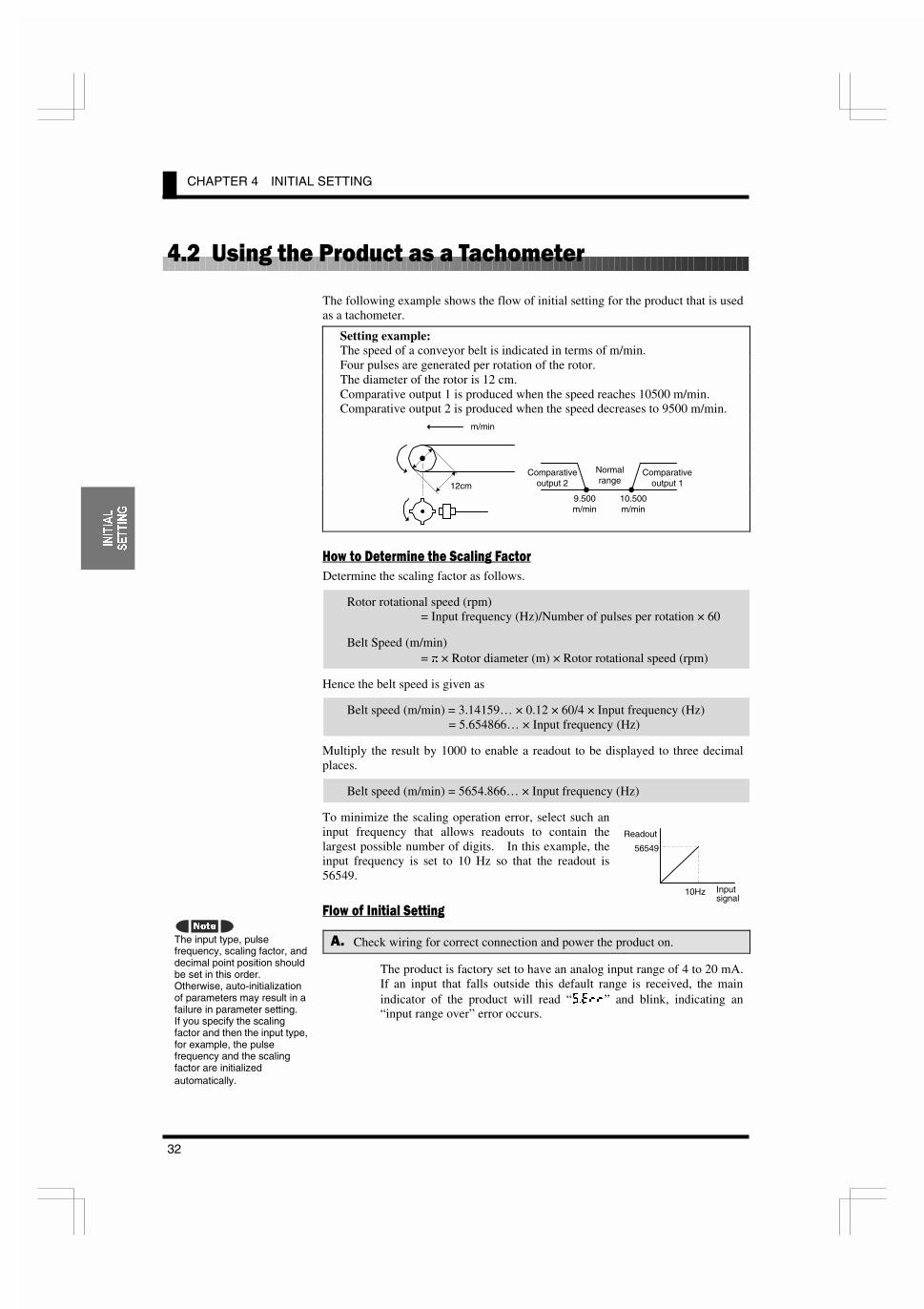
Setting example:The speed of a conveyor belt is indicated in terms of m/min.Four pulses are generated per rotation of the rotor.The diameter of the rotor is 12 cm.Comparative output 1 is produced when the speed reaches 10500 m/min.Comparative output 2 is produced when the speed decreases to 9500 m/min.
������� ��� �� �������������
Determine the scaling factor as follows.
Rotor rotational speed (rpm)= Input frequency (Hz)/Number of pulses per rotation × 60
Belt Speed (m/min)= S × Rotor diameter (m) × Rotor rotational speed (rpm)
Hence the belt speed is given as
Belt speed (m/min) = 3.14159… × 0.12 × 60/4 × Input frequency (Hz)= 5.654866… × Input frequency (Hz)
Multiply the result by 1000 to enable a readout to be displayed to three decimalplaces.
Belt speed (m/min) = 5654.866… × Input frequency (Hz)
To minimize the scaling operation error, select such aninput frequency that allows readouts to contain thelargest possible number of digits. In this example, theinput frequency is set to 10 Hz so that the readout is56549.
�������������� ��
�$ Check wiring for correct connection and power the product on.
The product is factory set to have an analog input range of 4 to 20 mA.If an input that falls outside this default range is received, the mainindicator of the product will read “J�<II” and blink, indicating an“input range over” error occurs.
The input type, pulsefrequency, scaling factor, anddecimal point position shouldbe set in this order.Otherwise, auto-initializationof parameters may result in afailure in parameter setting.If you specify the scalingfactor and then the input type,for example, the pulsefrequency and the scalingfactor are initializedautomatically.
1RWH
m/min
12cm9.500m/min
10.500m/min
Normalrange
Comparativeoutput 2
Comparativeoutput 1
Inputsignal
10Hz
Readout
56549
4.2 Using the Product as a Tachometer
33
,1,7,$/
6(77,1*
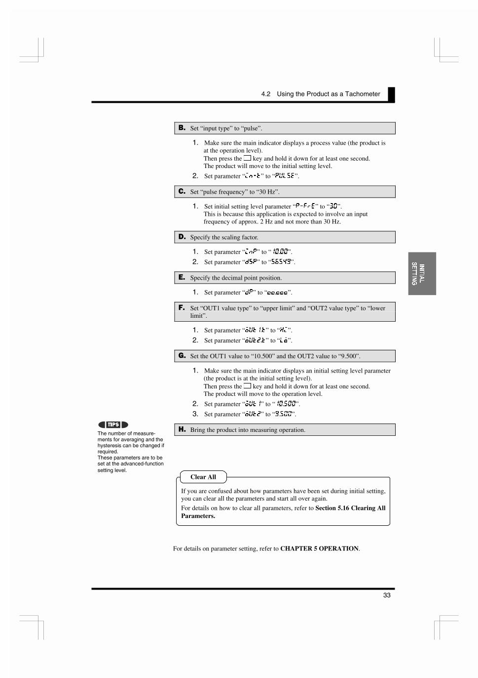
.$ Set “input type” to “pulse”.
1. Make sure the main indicator displays a process value (the product isat the operation level).Then press the . key and hold it down for at least one second.The product will move to the initial setting level.
2. Set parameter “@E�K” to “GLCJ<”.
�$ Set “pulse frequency” to “30 Hz”.
1. Set initial setting level parameter “G�=I<” to “��”.This is because this application is expected to involve an inputfrequency of approx. 2 Hz and not more than 30 Hz.
&$ Specify the scaling factor.
1. Set parameter “@EG” to “�����”.
2. Set parameter “;JG” to “�����”.
�$ Specify the decimal point position.
1. Set parameter “;G” to “������”.
�$ Set “OUT1 value type” to “upper limit” and “OUT2 value type” to “lowerlimit”.
1. Set parameter “FLK��K” to “?@”.
2. Set parameter “FLK��K” to “CF”.
�$ Set the OUT1 value to “10.500” and the OUT2 value to “9.500”.
1. Make sure the main indicator displays an initial setting level parameter(the product is at the initial setting level).Then press the . key and hold it down for at least one second.The product will move to the operation level.
2. Set parameter “FLK�” to “������”.
3. Set parameter “FLK�” to “�����”.
'$ Bring the product into measuring operation.
For details on parameter setting, refer to CHAPTER 5 OPERATION.
The number of measure-ments for averaging and thehysteresis can be changed ifrequired.These parameters are to beset at the advanced-functionsetting level.
If you are confused about how parameters have been set during initial setting,you can clear all the parameters and start all over again.
For details on how to clear all parameters, refer to Section 5.16 Clearing AllParameters.
Clear All
7,36

CHAPTER 4 INITIAL SETTING
34
,1,7,$/
6(77,1*
�����+ ���� ��������� ���'���������������$�������'��
The following example shows the flow of initial setting for the product that is usedas a digital indicator for PLC data.
Setting example:Full span 0H to 0FA0H (0 to 4000 in decimal) of a PLC analog input unit isscaled to 80.0 to 120.0 mm and displayed.Comparative output 1 is produced when the process value reaches 110.0 mm.Comparative output 2 is produced when the process value decreases to90.0 mm.
�������������� ��
�$ Check wiring for correct connection and power the product on.
The product is factory set to have an analog input range of 4 to 20 mA.If an input that falls outside this default range is received, the mainindicator of the product will read “J�<II” and blink, indicating an“input range over” error occurs..
.$ Set “input type” to “remote”.
1. Make sure the main indicator displays a process value (the product isat the operation level).Then press the . key and hold it down for at least one second.The product will move to the initial setting level.
2. Set parameter “@E�K” to “IDK”.
�$ Specify the scaling factor.
1. Set parameter “@EG��” to “�”.
2. Set parameter “;JG��” to “���”.
3. Set parameter “@EG��” to “����”.
4. Set parameter “;JG��” to “����”.
&$ Specify the decimal point position.
1. Set parameter “;G” to “������”.
�$ Set “OUT1 value type” to “upper limit” and “OUT2 value type” to “lowerlimit”.
1. Set parameter “FLK��K” to “?@”.
2. Set parameter “FLK��K” to “CF”.
Setting “input type” to“remote” sets the adjustmentlevel parameter “downloading(communication writing)” to“enable” automatically.The "CMW" indicator on thefront panel will be illuminated.
The input type, scaling factor,and decimal point positionshould be set in this order.Otherwise, auto-initializationof parameters may result in afailure in parameter setting.If you specify the scalingfactor and then the input type,for example, the scalingfactor is initializedautomatically.
1RWH
7,36
Input signal0 4000
120.0mm
80.0mm
Readout
90.0mm 110.0mm
Normalrange
Comparativeoutput 2
Comparativeoutput 1

4.3 Using the Product as a Digital Indicator for PLC Data
35
,1,7,$/
6(77,1*
�$ Specify communication parameters.
1. Make sure the main indicator displays an initial setting level parameter.Then press the . key.The product will move to the communication setting level.
2. Set parameter “L�EF” as appropriate.Exercise care to avoid assigning the same ID number to more than oneK3GN when connecting multiple products to one host PC.
3. Set parameter “9GJ” to the same value as in the host PC.
4. Set parameter “C<E” to the same value as in the host PC.
5. Set parameter “J9@K” to the same value as in the host PC.
6. Set parameter “GIKP” to the same value as in the host PC.
�$ Set the OUT1 value to “110.0” and the OUT2 value to “90.0”.
1. Make sure the main indicator displays an initial setting level parameter.Then press the . key and hold it down for at least one second.The product will move to the operation level.
2. Set parameter “FLK�” to “�����”.
3. Set parameter “FLK�” to “����”.
'$ Bring the product into measuring operation.
For details on parameter setting, refer to CHAPTER 5 OPERATION.
The number of measure-ments for averaging and thehysteresis can be changed ifrequired.These parameters are to beset at the advanced-functionsetting level.
If you are confused about how parameters have been set during initial setting,you can clear all the parameters and start all over again.
For details on how to clear all parameters, refer to Section 5.16 Clearing AllParameters.
Clear All
7,36

4.3 Using the Product as a Digital Indicator for PLC Data
37
23(5$7,21
5 ���������
5.1 LevelsCCCCCCCCCCCCCCCCCCCCCCCCCCCCCCCCCCCCCCCCCCCCCCCCCCCCC38
5.2 Moving among LevelsCCCCCCCCCCCCCCCCCCCCCCCCCCCCCCCCCCCCCC40
5.3 ParametersCCCCCCCCCCCCCCCCCCCCCCCCCCCCCCCCCCCCCCCCCCCCCCCCC42
5.4 Set Values CCCCCCCCCCCCCCCCCCCCCCCCCCCCCCCCCCCCCCCCCCCCCCCCC44
5.5 Operation LevelCCCCCCCCCCCCCCCCCCCCCCCCCCCCCCCCCCCCCCCCCCCC45Viewing and Changing /Forced-zero operation
5.6 Communication Writing Control CCCCCCCCCCCCCCCCCCCCCCCCCCCC47
5.7 Key Protect SettingCCCCCCCCCCCCCCCCCCCCCCCCCCCCCCCCCCCCCCCCC48
5.8 Selecting an Input Type (@E�K) CCCCCCCCCCCCCCCCCCCCCCCCCCCCC50
5.9 Selecting an Analog Range (I8E><) CCCCCCCCCCCCCCCCCCCCCCCC51
5.10 Selecting an Input-pulse Frequency Range (G�=I<) CCCCCCCCCC52
5.11 Specifying the Scaling Factor for Analog Input/Digital Data Display (@EG� , ;JG� ) CCCCCCCCCCCCCCCCCCCCCCCCC53
5.12 Specifying the Scaling Factorfor Input Pulse Frequency (@EG, ;JG) CCCCCCCCCCCCCCCCCCCCCCC55
5.13 Specifying the Decimal Point Position (;G) CCCCCCCCCCCCCCCCCC58
5.14 Selecting the Output Operating Action (FLK��K, FLK��K) CCCCC59
5.15 Specifying Communication Parameters CCCCCCCCCCCCCCCCCCCCCC60
5.16 Clearing All Parameters (@E@K)CCCCCCCCCCCCCCCCCCCCCCCCCCCCC62
5.17 Specifying the Number of Measurementsfor Averaging (8M>) CCCCCCCCCCCCCCCCCCCCCCCCCCCCCCCCCCCCCCC63
5.18 Specifying the Function of the Event Input (<M<EK) CCCCCCCCCC64
5.19 Specifying the Hysteresis (?PJ�, ?PJ�)CCCCCCCCCCCCCCCCCCCCC66
5.20 Specifying the Auto-zero Time (8LKF�Q) CCCCCCCCCCCCCCCCCCCC68
5.21 Specifying the Startup Compensation Time (J�KDI)CCCCCCCCCC70
5.22 Changing the Display Color (:FCFI)CCCCCCCCCCCCCCCCCCCCCCCC72
5.23 Changing the Display Auto-return Time (I<K)CCCCCCCCCCCCCCC74
5.24 Changing the Move-to-Protect-Level Time (GICK) CCCCCCCCCCC76
5.25 Changing the Send Waiting Time (J;NK) CCCCCCCCCCCCCCCCCCCC78
This chapter describes how to move among levels, changeparameters, and operate the product from the front panel.
�'�����

CHAPTER 5 OPERATION
38
23(5$7,21
)�����,�
In this manual, setting items of the product are grouped into seven levels asfollows.
Level Description Measurement
Protect
This level allows parameter setting forprotection against unauthorized or inadvertentkey operation. Access to protected levels orsetting items is disabled.
Yes
Operation
This level represents the normal operation statein which the product can accept input signalsand provide comparative outputs. Not onlyreadout of the current process value but alsoaccess to or changes of OUT set values areallowed at this level.The product enters this level at power-on.
Yes
Adjustment
This level permits communication writing tobe enabled or disabled. Even ifcommunication writing is disabled, reading isalways enabled.If your product has no communicationfunction, this level is not available.
Yes
Initial setting
This level allows initial setting of the inputtype, analog range, scaling factor and the like.Available only for the product withcommunication function.
No
Communicationsetting
This level allows setting of the baud rate, wordlength and other communication parameters.Available only for the product withcommunication function
No
Advanced-function setting
This level allows setting of the number ofmeasurements for averaging. Customizationssuch as a change in display color are alsopossible at this level.
No
Calibration
This level allows user calibration.Note that user calibration could causedeterioration in measuring accuracy of theproduct.
No
During operation of the product, the level indicator designates the current level.Alphabetic characters shown on the level indicator and their corresponding levelsare shown below.
Alphabetic character Level
G Protect level(OFF) Operation level8 Adjustment levelJ Initial Setting level: Communication level= Advanced-Function levelL User calibration level
������

5.2 Moving among Levels
39
23(5$7,21
)������,�����������,�
Operation levelAdjustment
level
Initial settinglevel
Communicationsetting level
Advanced-function setting
level
Calibrationlevel
Protect level
. key
. key
������
. key
. key
Hold . key downfor at least 1 sec.Release
the key
Continue holding . keydown for at least 2 sec.
Password"-0169"
Hold . keydown for atleast 1 sec.
������
.�/ keys
Releasethe key
Hold .+/keys downfor 5 sec.
Hold .+/keys down for atleast 1 sec.
*1
*1 The hold-down time can be changed using the "move to protect level" parameter.
Power the product off and then on again to exit from calibration level.
Power ON
*2
*2
*2 This level is not available if the product has no communication function.
Hold . keydown for atleast 1 sec.
Password"01201"
CHAPTER 5 OPERATION
40
23(5$7,21
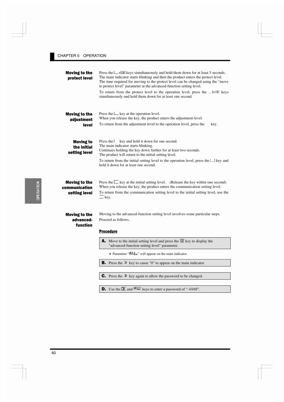
Press the .+/ keys simultaneously and hold them down for at least 5 seconds.The main indicator starts blinking and then the product enters the protect level.The time required for moving to the protect level can be changed using the “moveto protect level” parameter at the advanced-function setting level.
To return from the protect level to the operation level, press the .+/ keyssimultaneously and hold them down for at least one second.
Press the . key at the operation level.When you release the key, the product enters the adjustment level.
To return from the adjustment level to the operation level, press the . key.
Press the . key and hold it down for one second.The main indicator starts blinking.Continues holding the key down further for at least two seconds.The product will return to the initial setting level.
To return from the initial setting level to the operation level, press the . key andhold it down for at least one second.
Press the . key at the initial setting level. (Release the key within one second).When you release the key, the product enters the communication setting level.
To return from the communication setting level to the initial setting level, use the. key.
Moving to the advanced-function setting level involves some particular steps.
Proceed as follows.
���� ���
�$ Move to the initial setting level and press the / key to display the"advanced-function setting level" parameter.
x Parameter “8DFM” will appear on the main indicator.
.$ Press the 2 key to cause "0" to appear on the main indicator.
�$ Press the 2 key again to allow the password to be changed.
&$ Use the 2 and 4 keys to enter a password of “–0169”.
��� �������
������������
��� �������
�������� �
�����
��� ���
����� �����
����� �������
��� �������
���� �����
����� �������
��� �������
���� ����
�� ���

5.2 Moving among Levels
41
23(5$7,21
�$ Press the / key to save the password.
x If the password is correct, the product enters the advanced-function setting level.
x If the password is incorrect, the product remains at the initial setting level and itsmain indicator displays the next initial setting parameter.
� ��J
T
�J
T
�����J
T
����=
T
2 2
/ / /Use 2 and 4 keys toenter the specifiedpassword.
Correct password entered
Incorrect passwordentered
Next parameter at theinitial setting level
Advanced-function settinglevel

CHAPTER 5 OPERATION
42
23(5$7,21
)����������
Setting items at each level are called “parameters”.
Use the / key to select a parameter.
If the input range is changed, some parameters are set to default values.Therefore, set the input range first.
Communication setting level
@E�K
Initial setting level
. .
Press .+/ keys and holddown for at least 5 sec.
F8GK
@:GK
NKGK
QIGK
Operation/adjustment lockouts
Initial setting/communication lockouts
Setting change lockout
Forced-zero lockout
�����
FLK�
Current value
OUT1 upper-limit value
OUT2 upper-limit value
OUT1 value
FLK�?
FLK�C
FLK�
FLK$?
FLK$C
OUT1 lower-limit value
OUT2 value
OUT2 upper-limit value
:DNKCommunications writing control
/
/
Protect level
Operation level
Adjustment level
Press .+/ keys and holddown for at least 1 sec.
Press . key and holddown for at least 1 sec.
*1
*2
*2
*3
*4
*4
*5
/
/
/
/
/
/
/
/
/
Power-on
*8
Press . key and holddown for at least 3 sec.
/ Input type
I8E><
Input-pulse frequency range
Scaling display value 2
Analog range
G�=I<
@EG��
;JG��
@EG��
;JG��
Scaling input value 1
Scaling display value 1
Scaling input value 2
@EG
;JG
;G
Scaling input value
Scaling display value
Decimal point position
FLK�KOUT1 type
FLK$KOUT2 type
8DFM
Move to advanced-function level
*6
*7
*8
*8
*8
*8
*7
*7
*9
/
/
/
/
/
/
/
/
/
/
/
/
. .
*5
L�EF
9GJ
Communication unit No.
Word length
Baud rate
C<E
J9@K
GIKP
Stop bits
Parity bits
/
/
/
/
/
Pass"-016
5.3 Parameters
43
23(5$7,21
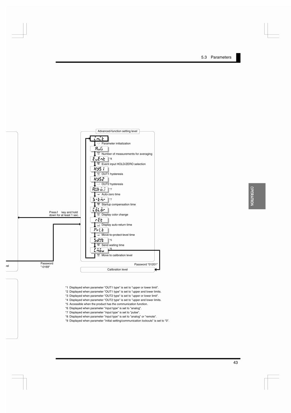
@E@K
Advanced-function setting level
velPassword"-0169"
Press . key and holddown for at least 1 sec.
8M>
Parameter initialization
Startup compensation time
Number of measurements for averaging
<M<EK
?PJ�
?PJ�
8LKF�Q
J�KDI
OUT1 hysteresis
OUT2 hysteresis
Auto-zero time
:FCFI
I<K
GICK
Display color change
Display auto-return time
Move-to-protect-level time
J;NKSend waiting time
:DFMMove to calibration level
/
Calibration level
Password "01201"
*7
*7
*5
/
/
/
/
/
/
/
/
/
/
/
*8
*6
Event input HOLD/ZERO selection
*1 Displayed when parameter "OUT1 type" is set to "upper or lower limit".*2 Displayed when parameter "OUT1 type" is set to "upper and lower limits.
*3 Displayed when parameter "OUT2 type" is set to "upper or lower limit".
*4 Displayed when parameter "OUT2 type" is set to "upper and lower limits.*5 Accessible when the product has the communication function.
*6 Displayed when parameter "input type" is set to "analog".
*7 Displayed when parameter "input type" is set to "pulse".*8 Displayed when parameter "input type" is set to "analog" or "remote".
*9 Displayed when parameter "initial setting/communication lockouts" is set to "0".

CHAPTER 5 OPERATION
44
23(5$7,21
)����%�-���
Parameter settings are called “set values”.Set values include those consisting of “numerics” and “alphabets”.
A state in which a set value is being displayed on the main indicator is called “themonitor state”.A state in which a set value can be changed is called “the change state”.
Perform the following steps to display or change a set value.
���� ���
�$ Press the 2 key when a parameter is displayed on the main indicator.The product enters the monitor state and the set value of the parameterwill be displayed on the main indicator.
x When the product is in the monitor state, “SV” in the operation indicator sectionis illuminated, indicating the readout on the main indicator is a set value.
.$ If you do not want to change the set value, press the / key in the monitorstate to go to the next parameter.
�$ Press the 2 key in the monitor state to cause the product to enter thechange state.
x A digit that can be changed will start blinking.
&$ Use the 2 and 4 key to change the set value.
x If no key is operated for five seconds, the product saves the current value andreturns to the monitor state automatically.
�$ Press the / key to go to the next parameter.
x The change in setting is saved in memory.
During setting of operation oradjustment level parameters,the return action of theproduct varies depending onthe “display auto-return time”setting.The display auto-return timedefaults to ten seconds.If the “display auto-returntime” is set to less than fiveseconds, e.g., three seconds,no key operation for threeseconds in the change statewill return the product to thecurrent value display mode,not to the monitor state.
7,36
�����J
T
����J
T
�����J
T
/
/
2 2
/ /Use the 2 and 4keys to change the setvalue.
Monitor state Change state
"SV" is illuminated. If no key is operatedfor 5 sec., the setvalue is saved andthe product returns tothe monitor state.
To next parameter

5.5 Operation Level
45
23(5$7,21
)�)���&�������,�
+��"�� �� �!���� ��� ��� �����The operation level allows you to check and change OUT set values.
The product continues measuring in the middle of checking and changing OUT setvalues.
���� ���
�$ Press the / key several times until parameter OUT2 is displayed on themain indicator.
.$ Press the 2 key to display the OUT2 value on the main indicator.
x The product enters the monitor state and shows the OUT2 value on the mainindicator.
x “SV” in the operation indicator section is illuminated, indicating the value shownon the main indicator is a set value.
x If you simply want to check the set value, proceed to step (.
�$ Press the 2 key in the monitor state to cause the product to enter thechange state.
x A digit that can be changed will start blinking.
&$ Use the 2 and 4 key to change the set value.
x If no key is operated for five seconds, the product saves the current value andreturns to the monitor state automatically.
�$ Press the / key several times to return to the current value display mode.
x The change in setting is saved in memory.
2SHUDWLRQ /HYHO
����
�����
T
�����
T
������
T
/
/
2 2
/ /
�����
T
Use the 2 and 4keys to change the setvalue.
Monitor state Change state
"SV" is illuminated.If no key is operatedfor 5 sec., the setvalue is saved andthe product returnsto the monitor state.
������
T
/
Current value
������
������
����
������
������

CHAPTER 5 OPERATION
46
23(5$7,21
Available OUT set values and their indications are as follows.
OUT set value Indication Description
OUT1 value FLK�When the process value increases or decreasesto this value, comparative output 1 is provided.
OUT1 upper-limitvalue FLK�?
OUT1 lower-limitvalue FLK�C
When the process value falls outside the rangespecified by these values, comparative output 1is provided.
OUT2 value FLK�When the process value increases or decreasesto this value, comparative output 2 is provided.
OUT2 upper-limitvalue FLK$?
OUT2 lower-limitvalue FLK$C
When the process value falls outside the rangespecified by these values, comparative output 2is provided.
�����*,�� �#�����
The forced-zero operation allows you to shift the current value to zero forcedly.For details, refer to CHAPTER 6 FUNCTION DESCRIPTION.
���� ��� (for forced-zero operation)
�$ Press the 4 key when a current value is displayed on the mainindicator. (Release the key within one second).
x The current value will be shifted to zero.
x “ZERO” in the operation indicator section is illuminated, indicating the currentvalue has been shifted to zero.
���� ��� (for forced-zero release operation)
.$ Press the 4 key and hold it down for at least one second when a shiftedvalue is displayed.
x The shifted value will be restored to the current value.
x “ZERO” in the operation indicator section will go off, indicating the currentvalue is no longer shifted.
The forced-zero operation isnot available if the input typeis set to "pulse".
If the 4 key on the frontpanel is used for executingthe forced-zero operation, theforced-zero process is storedin EEPROM. But if theforced-zero operation isexecuted via the event inputterminal or communications,the process is not stored.
If the current value is notnormal (e.g., the input signalis invalid, the process value isoutside the displayablerange, or no measurementsare made), the forced-zerofunction is inoperative.
7,36
1RWH
������
T
������
T4
4
Press 4 key and holdit down for at least 1 sec.
ZERO is illuminated.
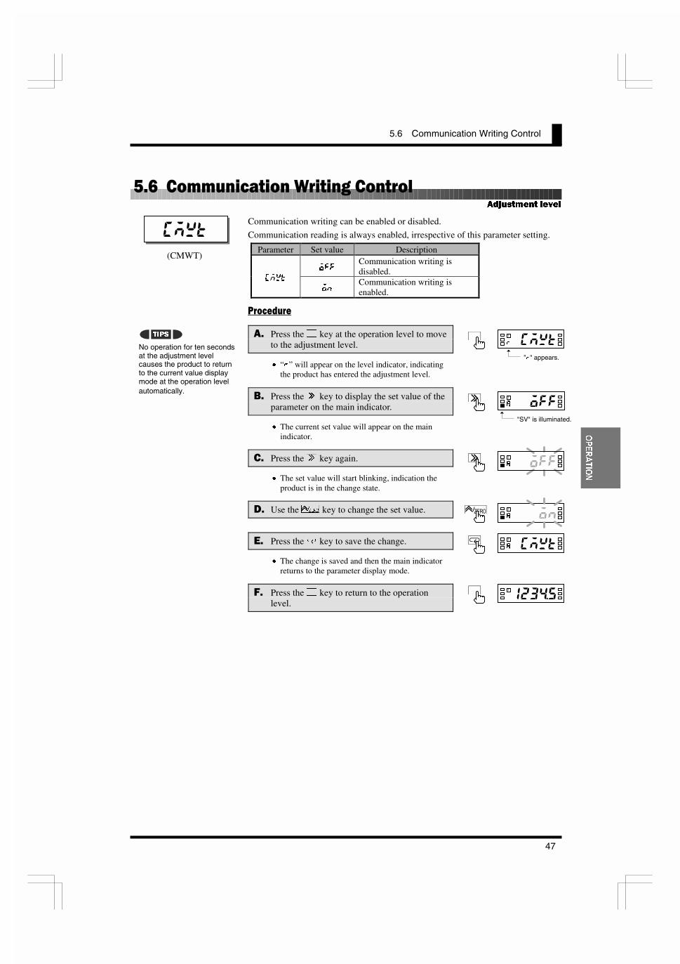
5.6 Communication Writing Control
47
23(5$7,21
)�*���������������.������������
Communication writing can be enabled or disabled.
Communication reading is always enabled, irrespective of this parameter setting.
Parameter Set value Description
F==Communication writing isdisabled.
:DNK
FECommunication writing isenabled.
���� ���
�$ Press the . key at the operation level to moveto the adjustment level.
x “I” will appear on the level indicator, indicatingthe product has entered the adjustment level.
.$ Press the 2 key to display the set value of theparameter on the main indicator.
x The current set value will appear on the mainindicator.
�$ Press the 2 key again.
x The set value will start blinking, indication theproduct is in the change state.
&$ Use the 4 key to change the set value.
�$ Press the / key to save the change.
x The change is saved and then the main indicatorreturns to the parameter display mode.
�$ Press the . key to return to the operationlevel.
$GMXVWPHQW OHYHO
No operation for ten secondsat the adjustment levelcauses the product to returnto the current value displaymode at the operation levelautomatically.
� ��
�����8
T�
�����8
T�
�� ��8
T�
�����8
T�
7,36
�����8
T�
"SV" is illuminated.
(CMWT)
�� ��I
T�
"I" appears.

CHAPTER 5 OPERATION
48
23(5$7,21
)�/��0#������%���
Key protect includes “operation/adjustment lockouts”, “initial setting/communica-tion lockouts”, “setting change lockout” and “forced-zero lockout”, and allowsrestrictions on various setting changes.
This types of key protect restrict the key operation at the operation and adjustmentlevels.
Operation levelParameter Set value Current value
displayOUT set value
display
Move toadjustment level
� Enable Enable Enable� Enable Enable DisableF8GK
� Enable Disable Disable
This types of key protect restrict the "moving among levels" operation.
Parameter Set valueMove to initial
setting level
Move tocommunication
setting level
Move toadvanced-
function settinglevel
� Enable Enable Enable� Enable Enable Disable@:GK
� Disable Disable Disable
This type of key protect restricts the key operation for setting changes.
It prohibits the product from entering the change state, except that the followingoperation is allowed.- Changes in set values of all parameters at the protect level- Move to the advanced-function level- Move to the calibration level
Parameter Set valueKey operation forsetting changes
F== EnableNKGK
FE Disable
This type of key protect restricts the key operation that activates or deactivates theforced-zero function.
It has no effect on forced-zero operation via the event input terminal.
Parameter Set valueKey operation for
activating or deactivatingthe forced-zero function
F== EnableQIGK
FE Disable
3URWHFW OHYHO
� ����������� �
��� �����
!�"���
����� ���� ��
!�"��
#�����$��
!�"��
����
�������
�������� �
!�"���
���
����
����
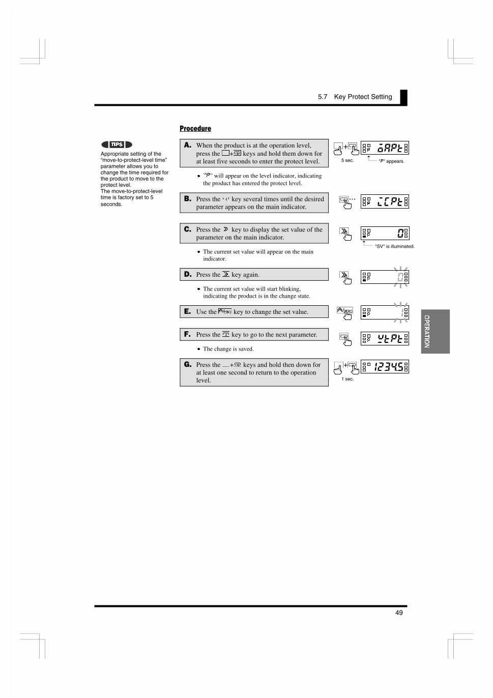
5.7 Key Protect Setting
49
23(5$7,21
���� ���
�$ When the product is at the operation level,press the .+/ keys and hold them down forat least five seconds to enter the protect level.
x pG” will appear on the level indicator, indicatingthe product has entered the protect level.
.$ Press the / key several times until the desiredparameter appears on the main indicator.
�$ Press the 2 key to display the set value of theparameter on the main indicator.
x The current set value will appear on the mainindicator.
&$ Press the 2 key again.
x The current set value will start blinking,indicating the product is in the change state.
�$ Use the 4 key to change the set value.
�$ Press the / key to go to the next parameter.
x The change is saved.
�$ Press the .+/ keys and hold then down forat least one second to return to the operationlevel.
Appropriate setting of the“move-to-protect-level time”parameter allows you tochange the time required forthe product to move to theprotect level.The move-to-protect-leveltime is factory set to 5seconds.
�����G
T�
�����G
T�
�����G
T�
7,36
�����G
T�
"SV" is illuminated.
�����8
T
1 sec.
���
�����G
T�+�
"G" appears.5 sec.
�����G
T �...

CHAPTER 5 OPERATION
50
23(5$7,21
)�1��%�����������&���#&
This parameter allows you to select one from three input types.
Parameter Set value Description
8E8C> Analog: The product can be used as a process meter.GLCJ< Pulse: The product can be used as a tachometer.
@E�K
IDKRemote: The product can be used as a digital dataindicator.
���� ���
�$ When the product is at the operation level,press the . key and hold it down for at leastthree seconds to enter the initial setting level.
x pJ” will appear on the level indicator, indicatingthe product has entered the initial setting level.
x The first parameter at the initial setting level is“@E�K”.
.$ Press the 2 key to display the set value of theparameter on the main indicator.
x The current set value will appear on the mainindicator.
�$ Press the 2 key again.
x The current set value will start blinking,indicating the product is in the change state.
&$ Use the 4 key to change the set value.
�$ Press the / key to go to the next parameter.
x The change is saved.
�$ Specify the values of other parameters relatedto the input type. (Refer to the Appendix).
�$ Press the . key and hold it down for at leastone second to return to the operation level.
,QLWLDO VHWWLQJ OHYHO
���
A change in input typeinitializes some parameters.� When the input type is set
to “analog”:Parameters “@EG��”,“;JG��”, “@EG��”, “;JG��”and “;G” are initializedaccording to the currentanalog range.The forced-zero function isdeactivated.
� When the input type is setto “pulse”:Parameter “;G” isinitialized according to thecurrent input-pulsefrequency range.
� When the input type is setto “remote”.Parameters “@EG��” and“;JG��” are set to “–19999”and “@EG��” and “;JG��”are set to “99999”.Parameter “;G” is set to“66666”.The forced-zero function isdeactivated.Data downloading is set to“enable”.
��� !J
T�
�� �"J
T�
���#"J
T�
7,36
�����J
T�
"J" appears.3 sec.
��� !J
T�
"SV" is illuminated.
�����8
T�
1 sec.

5.9 Selecting an Analog Range
51
23(5$7,21
)�2��%���������3������!���
This parameter allows you to select an analog input range.
Before selecting an analog range, you must set the input type parameter to“analog”.
Parameter Set value Measuring range
����4.00 to 20.00 mA/0.00 to 20.00 mA
���1.000 to 5.000V/0.000 to 5.000V
� –5.000 to 5.000V
I8E><
�� –10.000 to 10.000V
���� ���
�$ When the product is at the operation level,press the . key and hold it down for at leastthree seconds to enter the initial setting level.
x pJ” will appear on the level indicator, indicatingthe product has entered the initial setting level.
.$ Press the / key several times until parameter“I8E><” appears on the main indicator.
�$ Press the 2 key to display the set value of theparameter on the main indicator.
x The set value representing the current analogrange will appear on the main indicator.
&$ Press the 2 key again.
x The set value will start blinking, indicating theproduct is in the change state.
�$ Use the 4 key to change the set value.
�$ Press the / key to go to the next parameter.
x The change is saved.
�$ Specify the values of other parameters relatedto the analog range. (Refer to the Appendix).
'$ Press the . key and hold it down for at leastone second to return to the operation level.
,QLWLDO VHWWLQJ OHYHO
�����
A change in analog rangeinitializes some parameters.� Parameters “@EG��”,
“;JG��”, “@EG��”, “;JG��”and “;G” are initializedaccording to the currentanalog range.The forced-zero function isdeactivated.
�����J
T�
�����J
T�
������J
T�
7,36
�����J
T�
"J" appears.3 sec.
�����J
T�
"SV" is illuminated.
�����8
T�
1 sec.
�...#��!"J
T

CHAPTER 5 OPERATION
52
23(5$7,21
)��4��%�����������&�5&�� ���6���#�!���
This parameter allows you to select an input-pulse frequency range. The value ofthe parameter represents the upper limit of available ranges.
Before selecting an input-pulse frequency range, you must set the input typeparameter to “pulse”.
Parameter Set value Description
�� Measuring range: 0.05 to 30.00 HzG�=I<
�B Measuring range: 0.1 to 5000.0 Hz
If input signals come from relay contacts, set the range to “30 Hz”. Doing soeliminates chattering noise from input signals.
���� ���
�$ When the product is at the operation level,press the . key and hold it down for at leastthree seconds.
x p�” will appear on the level indicator, indicatingthe product has entered the initial setting level.
.$ Press the / key several times until parameter“G�=I<” appears on the main indictor.
�$ Press the 2 key to display the set value of theparameter on the main indicator.
x The current set value of the input-pulsefrequency range will appear on the mainindicator.
&$ Press the 2 key again.
x The set value will start blinking, indicating theproduct is in the change state.
�$ Use the 4 key to change the set value.
�$ Press the / key to go to the next parameter.
x The change is saved.
�$ Specify the values of other parameters relatedto the input-pulse frequency range. (Refer tothe Appendix).
'$ Press the . key and hold it down for at leastone second to return to the operation level.
,QLWLDO VHWWLQJ OHYHO
�����
A change in input-pulsefrequency range initializessome parameters.� Parameters “@EG”, “;JG”
and “;G” are initializedaccording to the currentinput-pulse frequencyrange.
����$J
T�
�����J
T�
�����J
T�
7,36
�����J
T�
"J" appears.3 sec.
����$J
T�
"SV" is illuminated.
�����8
T�
1 sec.
�...���#"J
T

5.11 Specifying the Scaling Factor for Analog Input/Digital Data Display
53
23(5$7,21
������������ ���������� ���������������� �������� ���������������
These parameters allow you to specify the scaling factor.
Before specifying the scaling factor, you must set the input type parameter to“analog” or “remote”.
Parameter Set value Description
@EG�� ����� ~ ����� Any input value;JG�� ����� ~ ����� Output value (readout) corresponding to @EG��@EG�� ����� ~ ����� Any input value;JG�� ����� ~ ����� Output value (readout) corresponding to @EG��
The input value can be set by teaching.
Inverse scaling where readout decreases with increasing input is also possible.
To allow a readout of 0.0 when the input value is 4.2 mA and a readout of 100.0when the input value is 20 mA, for example, set the parameters as follows.
- @EG�� = 4.20- ;JG�� = 0- @EG�� = 20.00- ;JG�� = 1000
Specify the decimal point position of the display value with parameter ;G.
For details, refer to Section 6.2 Scaling.
���� ���
�$ When the product is at the operation level,press the . key and hold it down for at leastthree seconds to enter the initial setting level.
x pJ” will appear on the level indicator, indicatingthe product has entered the initial setting level.
.$ Press the / key several times until parameter“@EG��” appears on the main indicator.
x pT” will be illuminated, indicating teaching ofthis parameter is possible.
x For the procedure of teaching, refer to the nextpage.
�$ Press the 2 key to display the set value of theparameter on the main indicator.
x The current set value of parameter “@EG��” willappear on the main indicator..
,QLWLDO VHWWLQJ OHYHO
����
The decimal point position ofparameters @EG�� and @EG��is automatically set asfollows.� When the input type is set
to "analog":4 to 20 mA:������1 to 5V: ������
±5V: ������
±10V: ������
� When the input type is setto "remote":
�����
�����
7,36
�����J
T�
"J" appears.3 sec.
�����J
T�
"SV" is illuminated.
�...������J
T
"T" is illuminated.
�����
����
;JG��
;JG��
@EG�� @EG�� Input value
Readout
;JG��
;JG��
@EG�� @EG�� Input value
Readout
Inverse scaling

CHAPTER 5 OPERATION
54
23(5$7,21
&$ Press the 2 key again.
x The set value starts blinking, indicating theproduct is in the change state.
�$ Use the 2 and 4 keys to change the setvalue.
�$ Press the / key to go to the next parameter“;JG��”.
x The change is saved and then “;JG��” willappear on the main indicator.
�$ Repeat steps & to ) for parameters “@EG��”and “;JG��”.
x When you finish setting of parameter “;JG��”,parameter “;G” will appear on the mainindicator.
'$ Press the . key and hold it down for at leastone second to return to the operation level.
The teaching function allows you to specify the value of parameters “@EG��” and“@EG��” without the need for any front panel key input.
���� ���
�$ Following step & (the product is in the monitor state), press the 4 key.
x pT” will start blinking, indicating the product is in teaching mode.
x Key entry permits the actual process value to be displayed on the main indicator.
6$ Press the 4 key again.
x The actual process value is set as the input value and then the product will returnto the monitor state.
x Pressing the / key instead of the 4 key in teaching mode cancels theteaching mode and the display on the main indicator changes to the nextparameter.
������J
T�
�����J
T
%����� �
�����J
T�
�����J
T��
�����8
T�
1 sec.
�����J
T
����J
T
�����J
T
/
/
2
2
/
/
Monitor state(Actual processvalue is displayed.)
Normal change state
"T" is illuminated,indicating teaching ispossible.
Next parameter
�����J
T
4
Teaching mode
To save the change andcause the product to enter themonitor state, press 4 key.
"T" blinks.
To save no changeand go to the nextparameter, press/ key.
"T" goes off.

5.12 Specifying the Scaling Factor for Input Pulse Frequency
55
23(5$7,21
����������� ��������� ������������� ���������������� �
These parameters allow you to specify the scaling factor.
Before specifying the scaling factor, you must set the input type parameter to“pulse”.
Parameter Set value Description
@EG ����� ~ ����� Any input value;JG ����� ~ ����� Output value (readout) corresponding to @EG
The input value can be set by teaching.To allow a readout of 10.000 when the input value is 4.2 kHz (= 4200 Hz), forexample, set the parameters as follows.
- @EG = 4200- ;JG = 10000
Specify the decimal point position of the display value with parameter ;G.
For details, refer to Section 6.2 Scaling.
���� ���
�$ When the product is at the operation level,press the . key and hold it down for at leastthree seconds to enter the initial setting level.
x pJ” will appear on the level indicator, indicatingthe product has entered the initial setting level.
.$ Press the / key several times until parameter“@EG” appears on the main indicator.
x pT” will be illuminated, indicating teaching ofthis parameter is possible.
x For the procedure of teaching, refer to the nextpage.
�$ Press the 2 key to display the set value of theparameter on the main indicator.
x The current set value of parameter “@EG” willappear on the indicator.
&$ Press the 2 key again.
x The set value will start blinking, indicating theproduct is in the change state.
�$ Use the 2 and 4 keys to change the setvalue.
,QLWLDO VHWWLQJ OHYHO
��
The decimal point position ofparameter “@EG” is automati-cally set depending on settingof the input-pulse frequencyrange as follows.
30 Hz: ������
5 kHz: �����
���
�����J
T�
�����J
T��
7,36
�����J
T�
"J" appears.3 sec.
�����J
T�
"SV" is illuminated.
�����J
T �..."T" is illuminated.
;JG
@EG Input value
Readout
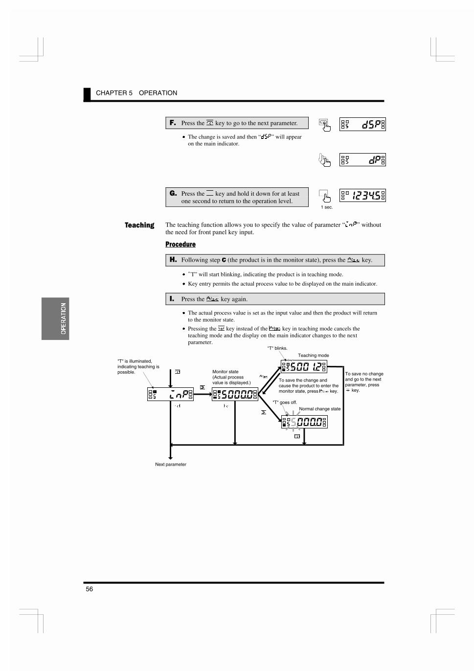
CHAPTER 5 OPERATION
56
23(5$7,21
�$ Press the / key to go to the next parameter.
x The change is saved and then “;JG” will appearon the main indicator.
�$ Press the . key and hold it down for at leastone second to return to the operation level.
The teaching function allows you to specify the value of parameter “@EG” withoutthe need for front panel key input.
���� ���
'$ Following step & (the product is in the monitor state), press the 4 key.
x pT” will start blinking, indicating the product is in teaching mode.
x Key entry permits the actual process value to be displayed on the main indicator.
�$ Press the 4 key again.
x The actual process value is set as the input value and then the product will returnto the monitor state.
x Pressing the / key instead of the 4 key in teaching mode cancels theteaching mode and the display on the main indicator changes to the nextparameter.
%����� �
�����J
T�
�����8
T�
1 sec.
�����J
T
����J
T
�����J
T
�����J
T
/
/
2
2
/
/
Monitor state(Actual processvalue is displayed.)
Normal change state
"T" is illuminated,indicating teaching ispossible.
Next parameter
�����J
T
4
Teaching mode
To save the change andcause the product to enter themonitor state, press 4 key.
"T" blinks.
To save no changeand go to the nextparameter, press/ key.
"T" goes off.

5.12 Specifying the Scaling Factor for Input Pulse Frequency
57
23(5$7,21
To minimize the scaling operation error, select such a scaling factor that permitsthe largest possible number of digits to be contained in scaling display values(DSP).
The relationship between the scaling input and display values for input pulsefrequency is represented by the following equation.
Scaling display value = D (multiplication factor) × input frequency (Hz)
Where D = DSP/INP
D is often an indivisible number such as 5.654866… particularly when the inputvalue is converted to a circumferential velocity. This is because such aconversion involves S.
There are innumerable combinations of scaling input values (INP) and scalingdisplay values (DSP) that result in D = 5.654866… as follows.
INP (Hz) DSP
12510···
5.654866···11.30973···28.27433···56.54866···
On the other hand, DSPs that are programmable are limited to 5-digit integers.This means that DSPs must be rounded off to the nearest integers as follows.
INP (Hz) Programmable DSP
12510···
00006000110002800057
Hence, if the input frequency is 1000 Hz, the error between the scaling result andthe ideal value increases with the decreasing number of digits contained in theDSP.
INP (Hz) Programmable DSPScaling result(readout)
Ideal value | Error |
12510···
00006000110002800057
6000550056005700
5655565556555655
3451555545
Select a combination of the DSP and INP so that the scaling output contains thelargest possible number of digits. Doing so minimizes the scaling operationerror.
&'��
������� �
����������
����� ��#�����
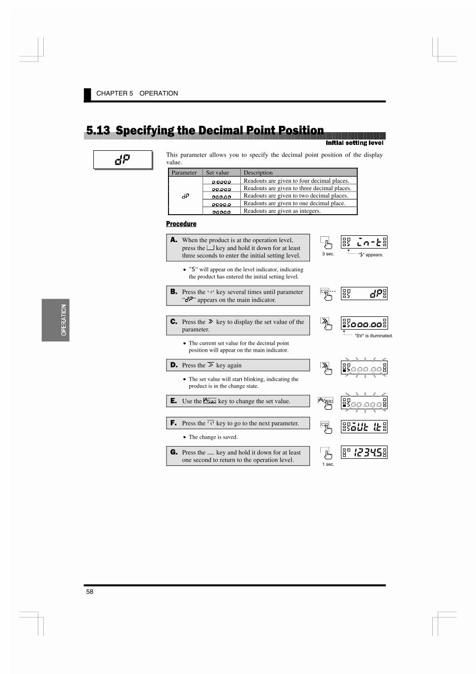
CHAPTER 5 OPERATION
58
23(5$7,21
)�����%&��$#���� �'������������� ����
This parameter allows you to specify the decimal point position of the displayvalue.
Parameter Set value Description
������ Readouts are given to four decimal places.������ Readouts are given to three decimal places.������ Readouts are given to two decimal places.������ Readouts are given to one decimal place.
;G
����� Readouts are given as integers.
���� ���
�$ When the product is at the operation level,press the . key and hold it down for at leastthree seconds to enter the initial setting level.
x pJ” will appear on the level indicator, indicatingthe product has entered the initial setting level.
.$ Press the / key several times until parameter“;G” appears on the main indicator.
�$ Press the 2 key to display the set value of theparameter.
x The current set value for the decimal pointposition will appear on the main indicator.
&$ Press the 2 key again
x The set value will start blinking, indicating theproduct is in the change state.
�$ Use the 4 key to change the set value.
�$ Press the / key to go to the next parameter.
x The change is saved.
�$ Press the . key and hold it down for at leastone second to return to the operation level.
,QLWLDO VHWWLQJ OHYHO
��
%%%�%%J
T�
%%�%%%J
T�
�����J
T�
�����J
T�
"J" appears.3 sec.
%%%�%%J
T�
"SV" is illuminated.
�����8
T�
1 sec.
�...#����J
T

5.14 Selecting the Output Operating Action
59
23(5$7,21
)�����%������ ���&���&������3����
These parameters allow you to select the operating action of outputs 1 and 2respectively.
Parameter Set value Description
?@ Upper limit: Upper-limit actionCF Lower limit: Lower-limit action
FLK��Kor
FLK��K ?@�CF Upper and lower limits: Outside-the-range action
For details, refer to Section 6.8 Comparative Output.
���� ���
�$ When the product is at the operation level,press the . key and hold it down for at leastthree seconds to enter the initial setting level..
x pJ” will appear on the level indicator, indicatingthe product has entered the initial setting level.
.$ Press the / key several times until parameter“FLK�K” appears on the main indicator.
�$ Press the 2 key to display the set value of theparameter on the main indicator.
x The current set value for the type of comparativeoutput will appear on the main indicator.
&$ Press the 2 key again.
x The set value will start blinking, indicating theproduct is in the change state.
�$ Use the 4 key to change the set value.
�$ Press the / key to display parameter“FLK��K” on the main indicator.
x The change is saved and then the next parameter“FLK��K” will appear on the main indicator.
�$ Repeat steps & to ) for parameter “FLK��K”.
x Parameter “8DFM” will appear on the mainindicator when you finish setting of parameter“FLK��K”.
'$ Press the . key and hold it down for at leastone second to return to the operation level.
,QLWLDO VHWWLQJ OHYHO
������
� To specify the OUT setvalue for the upper orlower-limit action, useparameters FLK� andFLK�.
� To specify the OUT setvalues for the outside-the-range action, useparameters FLK��?,FLK��C, FLK��? andFLK��C.
���&�J
T�
��� �J
T�
�����J
T�
�� ��J
T
7,36
�����J
T�
"J" appears.3 sec.
���&�J
T�
"SV" is illuminated.
�����8
T�
1 sec.
�...����'J
T
������
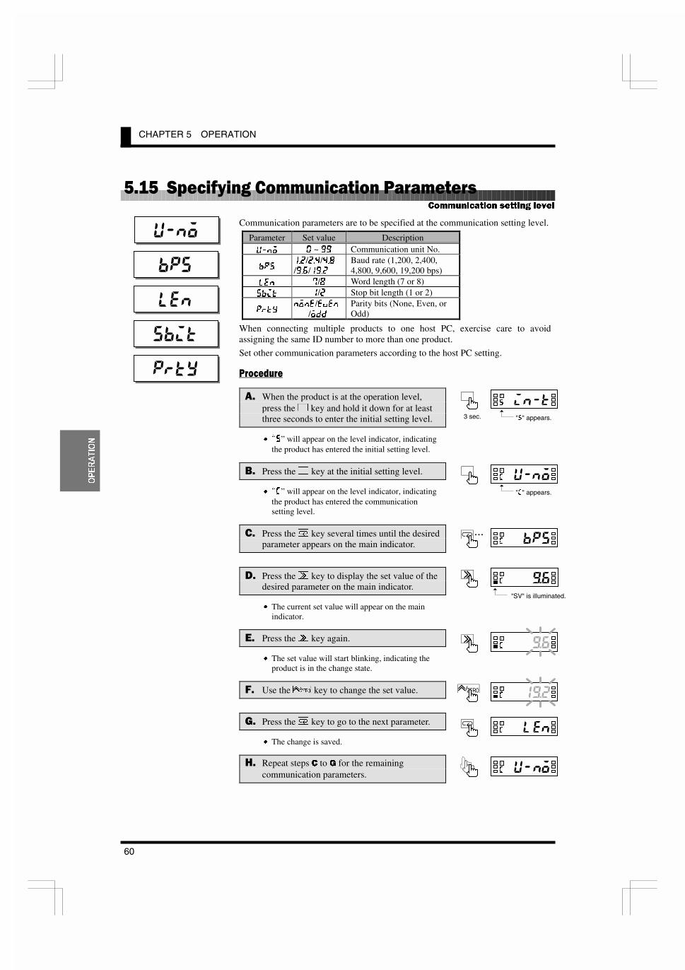
CHAPTER 5 OPERATION
60
23(5$7,21
)��)��%&��$#�����������������������
Communication parameters are to be specified at the communication setting level.
Parameter Set value Description
L�EF � ~ �� Communication unit No.
9GJ���/���/���/���/����
Baud rate (1,200, 2,400,4,800, 9,600, 19,200 bps)
C<E �/� Word length (7 or 8)J9@K �/� Stop bit length (1 or 2)
GIKPEFE</<M<E
/F;;Parity bits (None, Even, orOdd)
When connecting multiple products to one host PC, exercise care to avoidassigning the same ID number to more than one product.
Set other communication parameters according to the host PC setting.
���� ���
�$ When the product is at the operation level,press the . key and hold it down for at leastthree seconds to enter the initial setting level.
x pJ” will appear on the level indicator, indicatingthe product has entered the initial setting level.
.$ Press the . key at the initial setting level.
x p:” will appear on the level indicator, indicatingthe product has entered the communicationsetting level.
�$ Press the / key several times until the desiredparameter appears on the main indicator.
&$ Press the 2 key to display the set value of thedesired parameter on the main indicator.
x The current set value will appear on the mainindicator.
�$ Press the 2 key again.
x The set value will start blinking, indicating theproduct is in the change state.
�$ Use the 4 key to change the set value.
�$ Press the / key to go to the next parameter.
x The change is saved.
'$ Repeat steps & to * for the remainingcommunication parameters.
&RPPXQLFDWLRQ VHWWLQJ OHYHO
����
���
���
���
����
���(�:
T�
���(�:
T�
�� "�:
T�
�����:
T
�����J
T�
"J" appears.3 sec.
�����:
T�
":" appears.
���(�:
T�
"SV" is illuminated.
�...��)��:
T

5.15 Specifying Communication Parameters
61
23(5$7,21
�$ Press the . key to return to the initial settinglevel.
6$ Press the . key and hold it down for at leastone second to return to the operation level.
�����J
T�
�����8
T�
1 sec.

CHAPTER 5 OPERATION
62
23(5$7,21
)��*����������3���������
The clear all function can be used to initialize all parameters to factory settings.
Parameter Set value Description
F== –––@E@K
FE Parameters are all initialized.
This function is useful in restarting the setup of the product from the default state.
���� ���
�$ When the product is at the operation level,press the . key and hold it down for at leastthree seconds to enter the initial setting level.
x pJ” will appear on the level indicator, indicatingthe product has entered the initial setting level.
.$ Press the / key several times until parameter“8DFM” is displayed, and then enter password“–0169”.
x p=” will appear on the level indicator, indicatingthe product has entered the advanced-functionsetting level.
x The first parameter at the advanced-functionsetting level is “@E@K”.
x For details on how to move to the advanced-function setting level, refer to Section 5.2Moving among Levels.
�$ Press the 2 key to display the set value ofparameter “@E@K” on the main indicator.
x Set value “F==” will appear on the mainindicator.
&$ Press the 2 key again.
x The set value will start blinking, indicating theproduct is in the change state.
�$ Use the 4 key to change the set value to“FE”.
�$ Press the / key to go to the next parameter.
x All parameters are initialized.
x Parameter “@E@K” is also set to “F==”.
�$ Press the . key and hold it down for at leastone second to return to the initial setting level.
'$ Press the . key and hold it down for at leastone second to return to the operation level.
$GYDQFHG�IXQFWLRQ VHWWLQJ OHYHO
��
�����=
T�
�����=
T�
����!=
T�
�����J
T�
"J" appears.3 sec.
�����=
T
"=" appears.
�����J
T�
1 sec.
�����8
T�
1 sec.
�����=
T�
"SV" is illuminated.
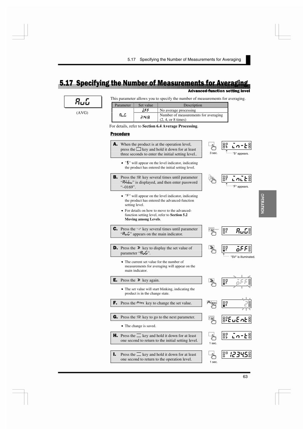
5.17 Specifying the Number of Measurements for Averaging
63
23(5$7,21
����������� ������������������������� ������������� �
This parameter allows you to specify the number of measurements for averaging.
Parameter Set value Description
F== No average processing8M>
�/�/�Number of measurements for averaging(2, 4, or 8 times)
For details, refer to Section 6.4 Average Processing.
���� ���
�$ When the product is at the operation level,press the . key and hold it down for at leastthree seconds to enter the initial setting level..
x pJ” will appear on the level indicator, indicatingthe product has entered the initial setting level.
.$ Press the / key several times until parameter“8DFM” is displayed, and then enter password“–0169”.
x p=” will appear on the level indicator, indicatingthe product has entered the advanced-functionsetting level.
x For details on how to move to the advanced-function setting level, refer to Section 5.2Moving among Levels.
�$ Press the / key several times until parameter“8M>” appears on the main indicator.
&$ Press the 2 key to display the set value ofparameter “8M>”.
x The current set value for the number ofmeasurements for averaging will appear on themain indicator.
�$ Press the 2 key again.
x The set value will start blinking, indicating theproduct is in the change state.
�$ Press the 4 key to change the set value.
�$ Press the / key to go to the next parameter.
x The change is saved.
'$ Press the . key and hold it down for at leastone second to return to the initial setting level.
�$ Press the . key and hold it down for at leastone second to return to the operation level.
$GYDQFHG�IXQFWLRQ VHWWLQJ OHYHO
���
�����=
T�
�����=
T�
"�"��=
T�
(AVG)
�����J
T�
"J" appears.3 sec.
�����=
T
"=" appears.
�����=
T�
"SV" is illuminated.
�����J
T�
1 sec.
�����8
T�
1 sec.
�...����!=
T

CHAPTER 5 OPERATION
64
23(5$7,21
)��1��%&��$#���� ����������$� �7,����&�
When the input type has been set to "analog" or "remote", this parameter allowsyou to specify the function of the event input (terminal e).
Before specifying the function of the event input, you must set the input type to“analog” or “remote”.
Parameter Set value Description
?FC; HOLD: The current process value is held.<M<EK
Q<IFZERO: The current process value is
forcedly shifted to zero.
For details, refer to Section 6.5 Process Value Hold.
���� ���
�$ When the product is at the operation level,press the . key and hold it down for at leastthree seconds to enter the initial setting level..
x pJ” will appear on the level indicator, indicatingthe product has entered the initial setting level.
.$ Press the / key several times until parameter“8DFM” is displayed, and then enter password“–0169”.
x p=” will appear on the level indicator, indicatingthe product has entered the advanced-functionsetting level.
x For details on how to move to the advanced-function setting level, refer to Section 5.2Moving among Levels.
�$ Press the / key several times until parameter“<M<EK” appears on the main indicator.
&$ Press the 2 key to display the set value ofparameter “<M<EK” on the main indicator.
x The current set value will appear on the mainindicator.
�$ Press the 2 key again.
x The set value will start blinking, indicating theproduct is in the change state.
�$ Use the 4 key to change the set value.
�$ Press the / key to go to the next parameter.
x The change is saved.
'$ Press the . key and hold it down for at leastone second to return to the initial setting level.
�����
�&� �=
T�
�*"#�=
T�
"&+��=
T�
(EVENT)
$GYDQFHG�IXQFWLRQ VHWWLQJ OHYHO
�����J
T�
"J" appears.3 sec.
�����=
T
"=" appears.
�&� �=
T�
"SV" is illuminated.
�����J
T�
1 sec.
�..."�"��=
T

5.18 Specifying the Function of the Event Input
65
23(5$7,21
�$ Press the . key and hold it down for at leastone second to return to the operation level. �����8
T�
1 sec.

CHAPTER 5 OPERATION
66
23(5$7,21
)��2��%&��$#���� �8# � �
These parameters allow you to specify the hysteresis for each of comparativeoutputs 1 and 2.
Parameter Set value Description
?PJ � ~ ���� 0 to 9999: Hysteresis
The setting of the decimal point position parameter at the initial setting level isreflected on the decimal point position of the hysteresis.
For details, refer to Section 6.9 Hysteresis.
���� ���
�$ When the product is at the operation level,press the . key and hold it down for at leastthree seconds to enter the initial setting level.
x pJ” will appear on the level indicator, indicatingthe product has entered the initial setting level.
.$ Press the / key several times until parameter“8DFM” is displayed, and then enter password“–0169”.
x p=” will appear on the level indicator, indicatingthe product has entered the advanced-functionsetting level.
x For details on how to move to the advanced-function setting level, refer to Section 5.2Moving among Levels.
�$ Press the / key several times until parameter“?PJ�” appears on the main indicator.
&$ Press the 2 key to display the set value ofparameter “?PJ�” on the main indicator.
x The current set value will appear on the mainindicator.
�$ Press the 2 key again.
x The set value will start blinking, indicating theproduct is in the change state.
�$ Use the 2 and 4 keys to change the setvalue.
�$ Press the / key to go to parameter “?PJ�”.
x The change is saved.
'$ Repeat steps ' to * for parameter “?PJ�”.
x The next parameter will appear on the mainindicator when you finish setting of parameter“?PJ�”.
����
�����=
T�
�����=
T��
"&+��=
T�
�� �#=
T
A hysteresis setting of “0” isassumed to be a hysteresissetting of “1”.
7,36
$GYDQFHG�IXQFWLRQ VHWWLQJ OHYHO
�&� �=
T�
"SV" is illuminated.
�����=
T
"=" appears.
�����J
T�
"J" appears.3 sec.
�..."&+��=
T
����

5.19 Specifying the Hysteresis
67
23(5$7,21
�$ Press the . key and hold it down for at leastone second to return to the initial setting level.
6$ Press the . key and hold it down for at leastone second to return to the operation level.
�����8
T�
1 sec.
�����J
T�
1 sec.

CHAPTER 5 OPERATION
68
23(5$7,21
)��4��%&��$#���� �3��59������
When the input type has been set to "pulse", this parameter allows you to specifythe auto-zero time.
Before specifying the auto-zero time, you must set the input type to “pulse”.
Parameter Set value Description
8LKF�Q ��� ~ ���� 0.0 to 19.9 seconds: Auto-zero time
The auto-zero time is the length of time required for the product to return thereadout to zero after pulse input interruption.
Set this parameter to a larger value than the expected time interval of input pulses(interval between input pulses). Failure to do so will result in incorrectmeasurements.
If the auto-zero time is too long, on the other hand, a long delay in lower-limitaction in response to a stop of rotation may result.
In the following application where a pulse is produced per rotation, for example,the input pulse frequency is 0.2 to 100 Hz, which means the time interval of inputpulses is 0.01 to 5 seconds.
The auto-zero time should therefore be set to five seconds or longer.
For details, refer to Section 6.3 Auto-zero/Startup Compensation.
���� ���
�$ When the product is at the operation level,press the . key and hold it down for at leastthree seconds to enter the initial setting level.
x pJ” will appear on the level indicator, indicatingthe product has entered the initial setting level.
.$ Press the / key several times until parameter“8DFM” is displayed, and then enter password“–0169”.
x p=” will appear on the level indicator, indicatingthe product has entered the advanced-functionsetting level.
x For details on how to move to the advanced-function setting level, refer to Section 5.2Moving among Levels.
�$ Press the / key several times until parameter“8LKF�Q” appears on the main indicator.
&$ Press the 2 key to display the set value ofparameter “8LKF�Q” on the main indicator.
x The current set value will appear on the mainindicator.
������
(AUTO.Z)
$GYDQFHG�IXQFWLRQ VHWWLQJ OHYHO
�����J
T�
"J" appears.3 sec.
�����=
T
"=" appears.
�&�(�=
T�
"SV" is illuminated.
12 ~ 6000 rpm
12 y 60�
= 5 (seconds)
�...�����*=
T
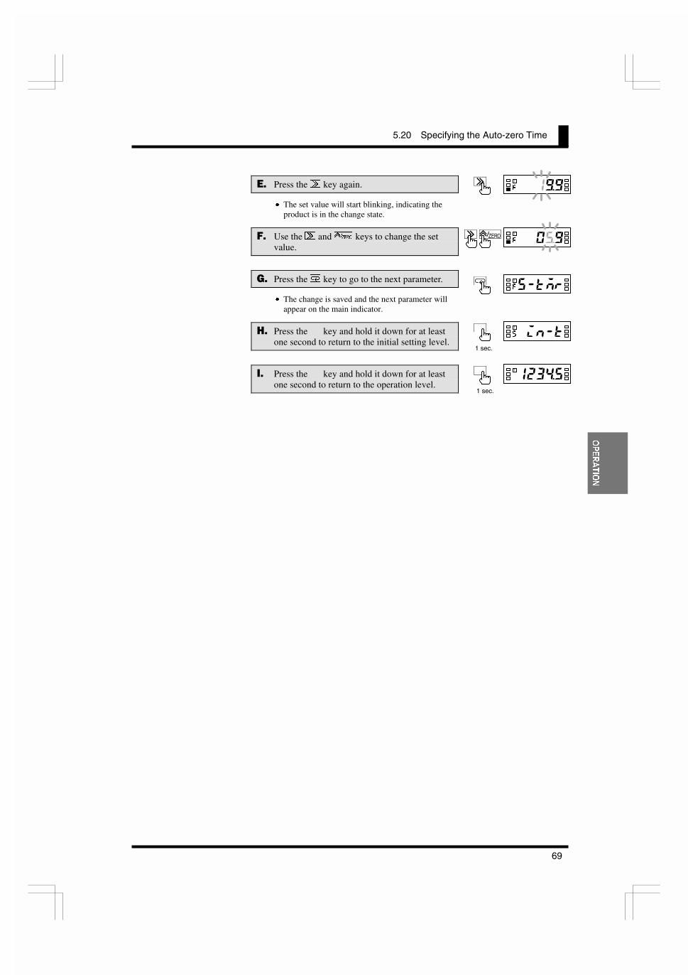
5.20 Specifying the Auto-zero Time
69
23(5$7,21
�$ Press the 2 key again.
x The set value will start blinking, indicating theproduct is in the change state.
�$ Use the 2 and 4 keys to change the setvalue.
�$ Press the / key to go to the next parameter.
x The change is saved and the next parameter willappear on the main indicator.
'$ Press the . key and hold it down for at leastone second to return to the initial setting level.
�$ Press the . key and hold it down for at leastone second to return to the operation level.
���(�=
T�
���,�=
T��
��� #=
T�
�����J
T�
1 sec.
�����8
T�
1 sec.
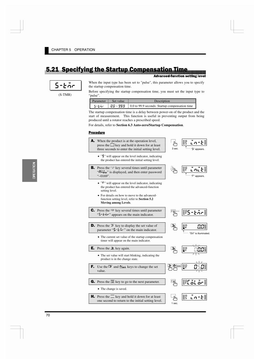
CHAPTER 5 OPERATION
70
23(5$7,21
)�����%&��$#���� �%���&����&� ��������
When the input type has been set to "pulse", this parameter allows you to specifythe startup compensation time.
Before specifying the startup compensation time, you must set the input type to“pulse”.
Parameter Set value Description
J�KDI ��� ~ ���� 0.0 to 99.9 seconds: Startup compensation time
The startup compensation time is a delay between power-on of the product and thestart of measurement. This function is useful in preventing output from beingproduced until a rotator reaches a prescribed speed.
For details, refer to Section 6.3 Auto-zero/Startup Compensation.
���� ���
�$ When the product is at the operation level,press the . key and hold it down for at leastthree seconds to enter the initial setting level.
x pJ” will appear on the level indicator, indicatingthe product has entered the initial setting level.
.$ Press the / key several times until parameter“8DFM” is displayed, and then enter password“–0169”.
x p=” will appear on the level indicator, indicatingthe product has entered the advanced-functionsetting level.
x For details on how to move to the advanced-function setting level, refer to Section 5.2Moving among Levels.
�$ Press the / key several times until parameter“J�KDI” appears on the main indicator.
&$ Press the 2 key to display the set value ofparameter “J�KDI” on the main indicator.
x The current set value of the startup compensationtimer will appear on the main indicator.
�$ Press the 2 key again.
x The set value will start blinking, indicating theproduct is in the change state.
�$ Use the 2 and 4 keys to change the setvalue.
�$ Press the / key to go to the next parameter.
x The change is saved.
'$ Press the . key and hold it down for at leastone second to return to the initial setting level.
��� �
�����=
T�
�� �#=
T�
���,�=
T��
(S-TMR)
$GYDQFHG�IXQFWLRQ VHWWLQJ OHYHO
�����J
T�
"J" appears.3 sec.
�����=
T
"=" appears.
�&���=
T�
"SV" is illuminated.
�����J
T�
1 sec.
�...��� #=
T

5.21 Specifying the Startup Compensation Time
71
23(5$7,21
�$ Press the . key and hold it down for at leastone second to return to the operation level.
�����8
T�
1 sec.

CHAPTER 5 OPERATION
72
23(5$7,21
)������ ������� �'� &��#������
This parameter allows you to change the display color of the main indicator.
Parameter Set value Description
>IE�I
Green – red: The display color is normally green, andchanges to red at comparative outputON.
>IE Green: The display color is always green.
I<;�>
Red – green: The display color is normally red, andchanges to green at comparative outputON.
:FCFI
I<; Red: The display color is always red.
For details, refer to Section 6.10 Display Color Change.
���� ���
�$ When the product is at the operation level,press the . key and hold it down for at leastthree seconds to enter the initial setting elvel.
x pJ” will appear on the level indicator, indicatingthe product has entered the initial setting level.
.$ Press the / key several times until parameter“8DFM” is displayed, and then enter password“–0169”.
x p=” will appear on the level indicator, indicatingthe product has entered the advanced-functionsetting level.
x For details on how to move to the advanced-function setting level, refer to Section 5.2Moving among Levels.
�$ Press the / key several times until parameter“:FCFI” appears on the main indicator.
&$ Press the 2 key to display the set value ofparameter “:FCFI” on the main indicator.
x The current set value of the display color willappear on the main indicator.
�$ Press the 2 key again.
x The set value will start blinking, indicating theproduct is in the change state.
�$ Use the 4 key to change the set value.
�$ Press the / key to go to the next parameter.
x The change is saved.
'$ Press the . key and hold it down for at leastone second to return to the initial setting level.
�����
!#��#=
T�
�*!#�=
T�
��#"�=
T�
$GYDQFHG�IXQFWLRQ VHWWLQJ OHYHO
�����J
T�
"J" appears.3 sec.
�����=
T
"=" appears.
!#��#=
T�
"SV" is illuminated.
�����J
T�
1 sec.
�...�� �#=
T

5.22 Changing the Display Color
73
23(5$7,21
�$ Press the . key and hold it down for at leastone second to return to the operation level.
�����8
T�
1 sec.

CHAPTER 5 OPERATION
74
23(5$7,21
)������ ������� �'� &��#�3��5��������
This parameter allows you to change the display auto-return time.
Parameter Set value Description
� 0 second: Display auto-return is not available.I<K
� ~ �� 1 to 99 seconds: Display auto-return time
If no key is operated for a prescribed time, the product returns to the current valuedisplay mode at the operation level.
This prescribed time is called the display auto-return time.
���� ���
�$ When the product is at the operation level,press the . key and hold it down for at leastthree seconds to enter the initial setting level.
x pJ” will appear on the level indicator, indicatingthe product has entered the initial setting level.
.$ Press the / key several times until parameter“8DFM” is displayed, and then enter password“–0169”.
x p=” will appear on the level indicator, indicatingthe product has entered the advanced-functionsetting level.
x For details on how to move to the advanced-function setting level, refer to Section 5.2Moving among Levels.
�$ Press the / key several times until parameter“I<K” appears on the main indicator.
&$ Press the 2 key to display the set value ofparameter “I<K” on the main indicator.
x The current set value of the display auto-returntime will appear on the main indicator.
�$ Press the 2 key again.
x The set value will start blinking, indicating theproduct is in the change state.
�$ Use the 2 and 4 keys to change the setvalue.
�$ Press the / key to go to the next parameter.
x The change is saved.
'$ Press the . key and hold it down for at leastone second to return to the initial setting level.
���
�����=
T�
�����=
T��
��# �=
T�
If the display auto-returnfunction is activated in themiddle of parameter setting,the product saves the currentvalue of the parameter andthen returns to the currentvalue display mode.
7,36
$GYDQFHG�IXQFWLRQ VHWWLQJ OHYHO
�����J
T�
"J" appears.3 sec.
�����=
T
"=" appears.
�&���=
T�
"SV" is illuminated.
�����J
T�
1 sec.
�...��#"�=
T

5.23 Changing the Display Auto-return Time
75
23(5$7,21
�$ Press the . key and hold it down for at leastone second to return to the operation level. �����8
T�
1 sec.
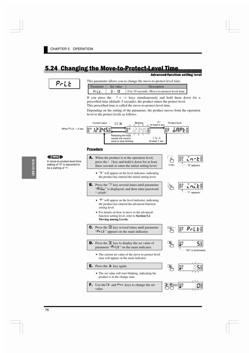
CHAPTER 5 OPERATION
76
23(5$7,21
)������ ������� ���,5�5����5�,�����
This parameter allows you to change the move-to-protect-level time.
Parameter Set value Description
GICK � ~ �� 0 to 19 seconds: Move-to-protect-level time
If you press the . + / keys simultaneously and hold them down for aprescribed time (default: 5 seconds), the product enters the protect level.This prescribed time is called the move-to-protect-level time.
Depending on the setting of the parameter, the product moves from the operationlevel to the protect levels as follows.
���� ���
�$ When the product is at the operation level,press the . key and hold it down for at leastthree seconds to enter the initial setting level.
x pJ” will appear on the level indicator, indicatingthe product has entered the initial setting level.
.$ Press the / key several times until parameter“8DFM” is displayed, and then enter password“–0169”.
x p=” will appear on the level indicator, indicatingthe product has entered the advanced-functionsetting level.
x For details on how to move to the advanced-function setting level, refer to Section 5.2Moving among Levels.
�$ Press the / key several times until parameter“GICK” appears on the main indicator.
&$ Press the 2 key to display the set value ofparameter “GICK” on the main indicator.
x The current set value of the move-to-protect-leveltime will appear on the main indicator.
�$ Press the 2 key again.
x The set value will start blinking, indicating theproduct is in the change state.
�$ Use the 2 and 4 keys to change the setvalue.
����
�����=
T�
�����=
T��
A move-to-protect-level timesetting of “0” is assumed tobe a setting of “1”.
7,36
$GYDQFHG�IXQFWLRQ VHWWLQJ OHYHO
�����J
T�
"J" appears.3 sec.
�����=
T
"=" appears.
�&���=
T�
"SV" is illuminated.
�����8
T
�����8
T
�����G
T
. /Current value Blinking Protect level.+/
At least 5 sec.
.+/At least 1 sec.
When GICK = 5 sec.
Releasing the keyscauses the currentvalue to stop blinking.
�...��# �=
T

5.24 Changing the Move-to-Protect-Level Time
77
23(5$7,21
�$ Press the / key to go to the next parameter.
x The change is saved.
'$ Press the . key and hold it down for at leastone second to return to the initial setting level.
�$ Press the . key and hold it down for at leastone second to return to the operation level.
�����=
T�
�����J
T�
1 sec.
�����8
T�
1 sec.

CHAPTER 5 OPERATION
78
23(5$7,21
)��)��� ������� �%���.���������
This parameter allows you to change the send waiting time.
Parameter Set value Description
J;NK � ~ �� 0 to 99 milliseconds: Send waiting time
The send waiting time is the time between reception of a command frame from thehost PC and return of a response frame to the host PC.
To optimize the responsivity, you should set the send waiting time somewhatlonger than the processing time that is required for the host PC to be ready forreception of a response frame after it sends a command frame.
���� ���
�$ When the product is at the operation level,press the . key and hold it down for at leastthree seconds to enter the initial setting level.
x pJ” will appear on the level indicator, indicatingthe product has entered the initial setting level.
.$ Press the / key several times until parameter“8DFM” is displayed, and then enter password“–0169”.
x p=” will appear on the level indicator, indicatingthe product has entered the advanced-functionsetting level.
x For details on how to move to the advanced-function setting level, refer to Section 5.2Moving among Levels.
�$ Press the / key several times until parameter“J;NK” appears on the main indicator.
&$ Press the 2 key to display the set value ofparameter “J;NK” on the main indicator.
x The current set value of the send waiting timewill appear on the main indicator.
�$ Press the 2 key again.
x The set value will start blinking, indicating theproduct is in the change state.
�$ Use the 2 and 4 keys to change the setvalue.
����
�����=
T�
�����=
T��
(SDWT)
$GYDQFHG�IXQFWLRQ VHWWLQJ OHYHO
Sending acommand frame
Inpreparationfor reception
Receiving aresponse frame
Receiving acommand frame
Sending a response frameWait for send
Host PC
K3GN
�����J
T�
"J" appears.3 sec.
�����=
T
"=" appears.
�&���=
T�
"SV" is illuminated.
�...�����=
T

5.25 Changing the Send Waiting Time
79
23(5$7,21
�$ Press the / key to go to the next parameter.
x The change is saved.
'$ Press the . key and hold it down for at leastone second to return to the initial setting level.
�$ Press the . key and hold it down for at leastone second to return to the operation level.
�� ��=
T�
�����J
T�
1 sec.
�����8
T�
1 sec.

5.25 Changing the Send Waiting Time
81
)81&7,21
'(6&5,37,21
7 ��������
&����������
6.1 Measurement CCCCCCCCCCCCCCCCCCCCCCCCCCCCCCCCCCCCCCCCCCCCCC82Analog Input Signal/Pulse Input Signal/Digital Data from PLC/PC
6.2 Scaling CCCCCCCCCCCCCCCCCCCCCCCCCCCCCCCCCCCCCCCCCCCCCCCCCCCC84
6.3 Auto-zero/Startup Compensation CCCCCCCCCCCCCCCCCCCCCCCCCCCC86
Auto-zero/Startup Compensation
6.4 Average Processing CCCCCCCCCCCCCCCCCCCCCCCCCCCCCCCCCCCCCCCC87
6.5 Event Input/Pulse InputCCCCCCCCCCCCCCCCCCCCCCCCCCCCCCCCCCCCC88
6.6 Process Value Hold CCCCCCCCCCCCCCCCCCCCCCCCCCCCCCCCCCCCCCCC89
6.7 Forced-zeroCCCCCCCCCCCCCCCCCCCCCCCCCCCCCCCCCCCCCCCCCCCCCCCC90
6.8 Comparative Output CCCCCCCCCCCCCCCCCCCCCCCCCCCCCCCCCCCCCCCC91
6.9 Hysteresis CCCCCCCCCCCCCCCCCCCCCCCCCCCCCCCCCCCCCCCCCCCCCCCCC92
6.10 Display Color Change CCCCCCCCCCCCCCCCCCCCCCCCCCCCCCCCCCCCCC93
This chapter describes available functions of the product.
�'�����
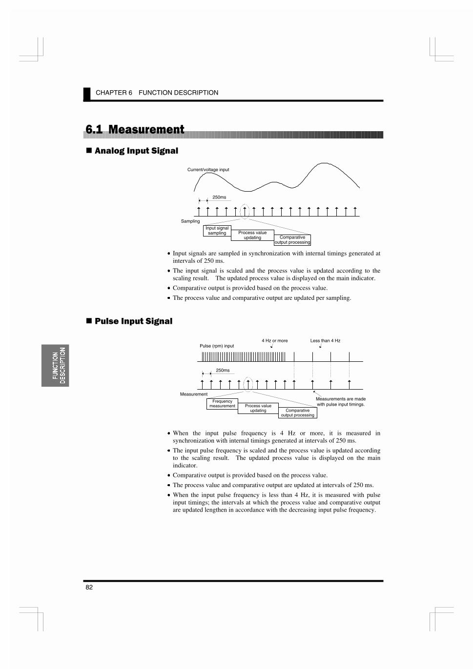
CHAPTER 6 FUNCTION DESCRIPTION
82
)81&7,21
'(6&5,37,21
*������ ����
����� �#�� �����
x Input signals are sampled in synchronization with internal timings generated atintervals of 250 ms.
x The input signal is scaled and the process value is updated according to thescaling result. The updated process value is displayed on the main indicator.
x Comparative output is provided based on the process value.
x The process value and comparative output are updated per sampling.
����� �#�� �����
x When the input pulse frequency is 4 Hz or more, it is measured insynchronization with internal timings generated at intervals of 250 ms.
x The input pulse frequency is scaled and the process value is updated accordingto the scaling result. The updated process value is displayed on the mainindicator.
x Comparative output is provided based on the process value.
x The process value and comparative output are updated at intervals of 250 ms.
x When the input pulse frequency is less than 4 Hz, it is measured with pulseinput timings; the intervals at which the process value and comparative outputare updated lengthen in accordance with the decreasing input pulse frequency.
Pulse (rpm) input4 Hz or more Less than 4 Hz
250ms
Frequencymeasurement Process value
updating Comparativeoutput processing
MeasurementMeasurements are madewith pulse input timings.
Current/voltage input
Sampling
250ms
Input signalsampling Process value
updating Comparativeoutput processing

6.1 Measurement
83
)81&7,21
'(6&5,37,21
&������ &��� ��) �1�-��
When the product is used as a remote indicator, the host PC not only provideslogging of measured data and remote control to the product but also acts as inputequipment for the product. The product performs measurement, scaling andcomparative output processing.
The product measures serial data as follows.
x Data from the host PC is stored with timings of data transmission. When newdata is received, old data is replaced with the new one.
x Stored data is fetched as input values in synchronization with internal timingsgenerated at intervals of 250 ms, irrespective of timing signals received fromthe host PC.
x The input value is scaled and the process value is updated according to thescaling result. The updated process value is displayed on the main indicator.
x Comparative output is provided based on the process value.
x The process value and comparative output are updated with internal timingsgenerated at intervals of 250 ms.
Sampling
250ms
Input signalsampling Process value
updating Comparativeoutput processing
Data from host PC
1 2 3 4
3 4 4 4
5
5
������
T
K3GN withcommunication function
Serial data asinput signals

CHAPTER 6 FUNCTION DESCRIPTION
84
)81&7,21
'(6&5,37,21
*����%������
Scaling is to convert sampled input values to process values in sequence using apredetermined scaling formula.
Scaling allows conversion of input values to process values in easy-to-understandnotation.
The scaling formula for analog input and digital data is as follows.
12
1221
12
12
INPINP
DSPINPDSPINPinp
INPINP
DSPDSPdsp
�
����
�
�
Where;
INP1: Input valueDSP1: Process value corresponding to input value INP1INP2: Input valueDSP2: Process value corresponding to input value INP2inp: Input value sampleddsp: Process value corresponding to inp
Enter INP1, DSP1, INP2 and DSP2 to specify the scaling factor.
This way of specifying the scaling factor permits flexible scaling; inverse scalingwhere the process value decreases with the increasing input value is also possible.
For details on how to specify the scaling factor, refer to Section 5.11 Specifyingthe Scaling Factor for Analog Input/Digital Data Display.
����� ��#�����
���� ����� ���
� ��������������
Input value(scaling input)
Process value(scaling output)
Conversionequation
Processvalue
Input value
Flexible scaling

6.2 Scaling
85
)81&7,21
'(6&5,37,21
The scaling formula for pulse input is as follows.
inpINP
DSPdsp
Where;
INP: Input pulse frequency (Hz)DSP: Process value corresponding to input pulse frequency INPinp: Input pulse frequency sampled (Hz)dsp: Process value corresponding to inp
Enter INP and DSP to specify the scaling factor.
Conversion of the input pulse frequency to the rotational speed involves thefollowing scaling formula.
inpP
dsp60
)rpm(
Where;
P: Number of pulses per rotationinp: Input pulse frequency (Hz)dsp: Rotational speed (rpm)
Conversion of the input pulse frequency to the circumferential speed involves thefollowing scaling formula.
inpP
Rdsp60
min)/m( �� S
Where;
S: Circular constantP: Number of pulses per rotationR: Diameter of rotator (m)inp: Input pulse frequency (Hz)dsp: Circumferential speed (m/min)
����� �
#��������
������� ���
Unit conversionrps = rpm/60
Unit conversionm/s = (m/min)/60mm/s = {(m/min)×1000}/60
7,36
7,36
Processvalue
Input value
Scaling where the zeropoint is fixed is allowed.
P: Number of teeth
P: Number of teethR: Diameter of rotator
R

CHAPTER 6 FUNCTION DESCRIPTION
86
)81&7,21
'(6&5,37,21
*����3��59���%���&����&� ����
����*,��The product has an input-pulse frequency range of 0.05 to 30 Hz or 0.1 to 5 kHz,and hence the maximum interval between pulses is 20 seconds.
This means that the product may provide a lower-limit action signal as late as amaximum of 20 seconds after receiving the last pulse, which results in a poorresponsivity for the lower-limit action.
To eliminate such a situation, the product has an auto-zero function that shifts theinput pulse frequency to zero forcedly when no pulse is received for apredetermined time.
This function improves the product responsivity for the lower-limit action.
The time between reception of the last pulse and zero-shifting of the input pulsefrequency is called the auto-zero time. The auto-zero time can be specified usingthe “auto-zero time” parameter.
Specify the auto-zero time somewhat longer than the expected longest intervalbetween input pulses.
�����# ��)#������
The product has a startup compensation timer that prevents measurement for apredetermined time after power-on.
This function is useful in keeping the product in wait state until a rotator reachesthe steady-state speed.
The time between power-on the product and the start of measurement can bespecified using the “startup compensation time” parameter.
Power-onUpper threshold
Lower threshold
Startupcompensation time
Rotationalspeed of rotator
Measurement Measurement in progress
Readout �����
Wait state
Normal indication
Measurement preventeduntil the rotator reachesthe steady-state speed
Input pulse
Pulse frequency
OUT set value(Lower-limit action)
Auto-zero time
Comparative output(Auto-zero function activated)
Comparative output(Auto-zero function canceled)
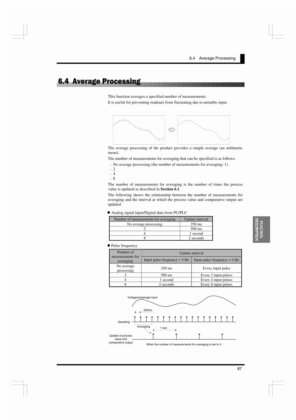
6.4 Average Processing
87
)81&7,21
'(6&5,37,21
*����3,�������� ���
This function averages a specified number of measurements.
It is useful for preventing readouts from fluctuating due to unstable input.
The average processing of the product provides a simple average (an arithmeticmean).
The number of measurements for averaging that can be specified is as follows.
- No average processing (the number of measurements for averaging: 1)- 2- 4- 8
The number of measurements for averaging is the number of times the processvalue is updated as described in Section 6.1.
The following shows the relationship between the number of measurements foraveraging and the interval at which the process value and comparative output areupdated.
z Analog signal input/Digital data from PC/PLC
Number of measurements for averaging Update intervalNo average processing 250 ms
2 500 ms4 1 second8 2 seconds
z Pulse frequency
Update intervalNumber ofmeasurements for
averaging Input pulse frequency t 4 Hz Input pulse frequency < 4 Hz
No averageprocessing
250 ms Every input pulse
2 500 ms Every 2 input pulses4 1 second Every 4 input pulses8 2 seconds Every 8 input pulses
Voltage/amperage input
250ms
Averaging
Sampling
Update of processvalue and
comparative output
1 sec.
When the number of measurements for averaging is set to 4
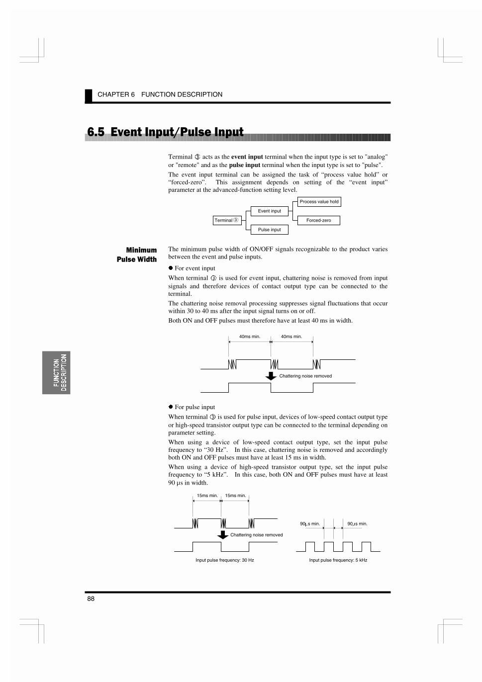
CHAPTER 6 FUNCTION DESCRIPTION
88
)81&7,21
'(6&5,37,21
*�)��7,����&����� ���&�
Terminal e acts as the event input terminal when the input type is set to "analog"or "remote" and as the pulse input terminal when the input type is set to "pulse".
The event input terminal can be assigned the task of “process value hold” or“forced-zero”. This assignment depends on setting of the “event input”parameter at the advanced-function setting level.
The minimum pulse width of ON/OFF signals recognizable to the product variesbetween the event and pulse inputs.
z For event input
When terminal e is used for event input, chattering noise is removed from inputsignals and therefore devices of contact output type can be connected to theterminal.
The chattering noise removal processing suppresses signal fluctuations that occurwithin 30 to 40 ms after the input signal turns on or off.
Both ON and OFF pulses must therefore have at least 40 ms in width.
z For pulse input
When terminal e is used for pulse input, devices of low-speed contact output typeor high-speed transistor output type can be connected to the terminal depending onparameter setting.
When using a device of low-speed contact output type, set the input pulsefrequency to “30 Hz”. In this case, chattering noise is removed and accordinglyboth ON and OFF pulses must have at least 15 ms in width.
When using a device of high-speed transistor output type, set the input pulsefrequency to “5 kHz”. In this case, both ON and OFF pulses must have at least90 Ps in width.
�� ����
�����������
Terminal
Event input
Pulse input
Process value hold
Forced-zero3
Chattering noise removed
40ms min. 40ms min.
Chattering noise removed
15ms min. 15ms min.
Input pulse frequency: 30 Hz
90Ps min. 90Ps min.
Input pulse frequency: 5 kHz
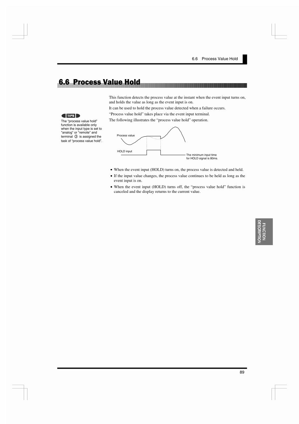
6.6 Process Value Hold
89
)81&7,21
'(6&5,37,21
*�*������ �-����8���
This function detects the process value at the instant when the event input turns on,and holds the value as long as the event input is on.
It can be used to hold the process value detected when a failure occurs.
“Process value hold” takes place via the event input terminal.
The following illustrates the “process value hold” operation.
x When the event input (HOLD) turns on, the process value is detected and held.
x If the input value changes, the process value continues to be held as long as theevent input is on.
x When the event input (HOLD) turns off, the “process value hold” function iscanceled and the display returns to the current value.
The “process value hold”function is available onlywhen the input type is set to"analog" or "remote" andterminal t is assigned thetask of “process value hold”.
7,36
Process value
HOLD inputThe minimum input timefor HOLD signal is 80ms.

CHAPTER 6 FUNCTION DESCRIPTION
90
)81&7,21
'(6&5,37,21
*�/�������59��
This feature shifts a process value to zero, and can be used to evaluate and displaythe deviation of a process value from a reference value.
The forced-zero function can be activated by using the 4 key on the front panel,via the event input terminal, or communications
The following illustrates the forced-zero and forced-zero cancel operation.
x When ZERO input turns on, the current process value is shifted to zeroforcedly.
x Thereafter, measurements are made relative to the zero point.
x When ZERO input turns on while the forced-zero function has been activated,the current process value is further shifted to zero.
x When ZERO input is on for one second, the forced-zero operation is canceled.
Because the forced-zero and forced-zero cancel operation using the 4 key isstored in EEPROM, the forced-zero state is alive even if the power is turned offand on again.
In contrast, the forced-zero and forced-zero cancel operation via event inputterminal is not stored in EEPROM.
If the forced-zero operation is executed via the event input terminal after it isactivated by key entry, the forced-zero operation via the event input terminal takeseffect.
The forced-zero function isavailable via the event inputterminal only when the inputtype is set to "analog" or"remote" and terminal e isassigned the task of “forced-zero execution”.
The forced-zero function isnot available when the inputtype is set to "pulse". Keyentry for the forced-zerooperation is also ignored.
1RWH
7,36
Process value
ZERO inputThe minimum input timefor HOLD signal is 80ms.
Forced-zero value(shifted value)
Measurement valueafter executing theforced-zero function
1 sec.
Forced-zeroexecuted
Forced-zero
canceled
1 sec.
4 key entry
Event input
The forced-zero cancel operation isignored if the forced-zero functionhas already been deactivated.
Forced-zeroexecuted
Forced-zeroexecuted
Forced-zeroexecuted
Forced-zeroexecuted
Forced-zeroexecuted
Forced-zero
canceled
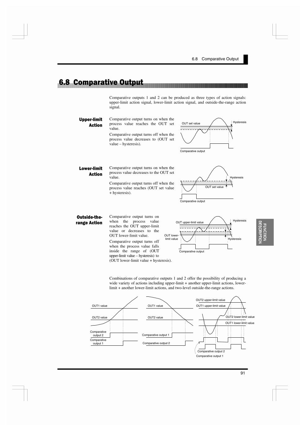
6.8 Comparative Output
91
)81&7,21
'(6&5,37,21
*�1�����&����,���&�
Comparative outputs 1 and 2 can be produced as three types of action signals:upper-limit action signal, lower-limit action signal, and outside-the-range actionsignal.
Comparative output turns on when theprocess value reaches the OUT setvalue.
Comparative output turns off when theprocess value decreases to (OUT setvalue – hysteresis).
Comparative output turns on when theprocess value decreases to the OUT setvalue.
Comparative output turns off when theprocess value reaches (OUT set value+ hysteresis).
Comparative output turns onwhen the process valuereaches the OUT upper-limitvalue or decreases to theOUT lower-limit value.
Comparative output turns offwhen the process value fallsinside the range of (OUTupper-limit value – hysteresis) to(OUT lower-limit value + hysteresis).
Combinations of comparative outputs 1 and 2 offer the possibility of producing awide variety of actions including upper-limit + another upper-limit actions, lower-limit + another lower-limit actions, and two-level outside-the-range actions.
(����������
����
!'��������
����
������������
�� �������
OUT set value
Comparative output
Hysteresis
OUT set value
Comparative output
Hysteresis
OUT lower-limit value
Comparative output
OUT upper-limit valueHysteresis
Hysteresis
OUT1 value
OUT2 value
Comparativeoutput 2
Comparativeoutput 1
OUT1 value
OUT2 value
Comparative output 2
Comparative output 1
OUT1 upper-limit value
Comparative output 2
Comparative output 1
OUT2 upper-limit value
OUT2 lower-limit value
OUT1 lower-limit value
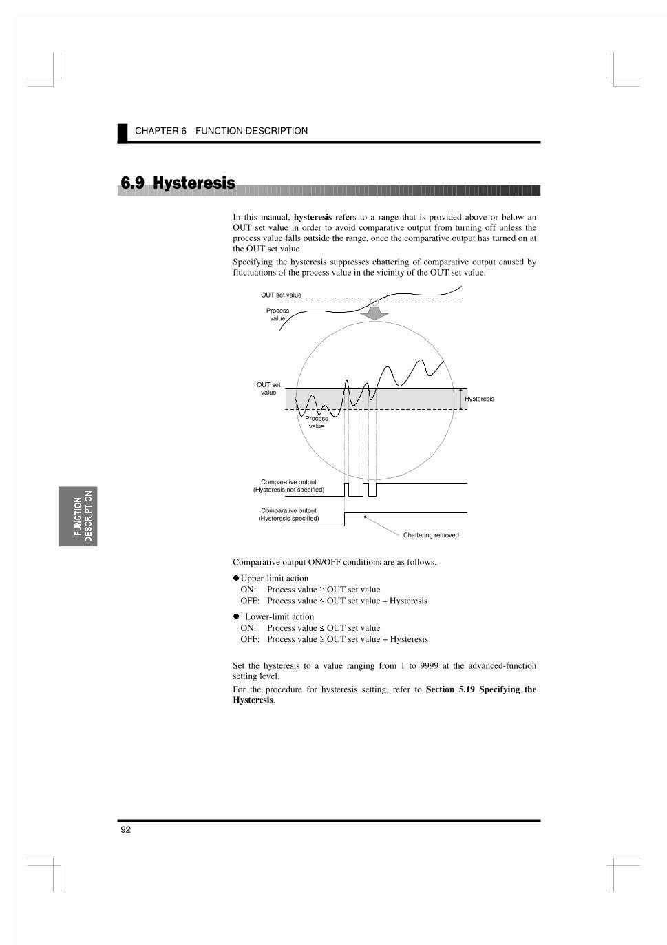
CHAPTER 6 FUNCTION DESCRIPTION
92
)81&7,21
'(6&5,37,21
*�2��8# � �
In this manual, hysteresis refers to a range that is provided above or below anOUT set value in order to avoid comparative output from turning off unless theprocess value falls outside the range, once the comparative output has turned on atthe OUT set value.
Specifying the hysteresis suppresses chattering of comparative output caused byfluctuations of the process value in the vicinity of the OUT set value.
Comparative output ON/OFF conditions are as follows.
z Upper-limit actionON: Process value t OUT set valueOFF: Process value d OUT set value – Hysteresis
z Lower-limit actionON: Process value d OUT set valueOFF: Process value t OUT set value + Hysteresis
Set the hysteresis to a value ranging from 1 to 9999 at the advanced-functionsetting level.
For the procedure for hysteresis setting, refer to Section 5.19 Specifying theHysteresis.
OUT set value
Processvalue
OUT setvalue
Processvalue
Hysteresis
Comparative output(Hysteresis not specified)
Comparative output(Hysteresis specified)
Chattering removed

6.10 Display Color Change
93
)81&7,21
'(6&5,37,21
*��4��'� &��#�������� ���
The display color of the main indicator can be changed.
This feature can be used to vary the display color of the gang-mounted productsdepending on their importance or to give greater prominence to indications on themain indicator of certain products in an emergency.
Four display color change options are available.
Green to red: The display color of the main indicator is green when both ofcomparative outputs 1 and 2 is off, and changes to red when eitherof the comparative outputs turns on.
Always green: The display color is always green.
Always red: The display color is always red.
Red to green: The display color is red when both of comparative outputs 1 and 2is off, and changes to green when either of the comparative outputsturns on.
Select one among these options at the advanced-function setting level.
For the procedure for programming of display colors, refer to Section 5.22Changing the Display Color.
������
T
OUT2 value
OUT1 value ������
T
����
T
Green
Red
Red
Display color change from green to red

6.10 Display Color Change
95
&20081,�
&$7,216
8 ��((����������
7.1 Communication ProtocolsCCCCCCCCCCCCCCCCCCCCCCCCCCCCCCCCCCC96CompoWay/F Communication Protocol/Communication Specification/Transmission Procedure
7.2 Data Format Structure CCCCCCCCCCCCCCCCCCCCCCCCCCCCCCCCCCCCCC97Command Frame/Response Frame
7.3 Structure of Command/Response Text CCCCCCCCCCCCCCCCCCCCCCC99
7.4 Variable AreaCCCCCCCCCCCCCCCCCCCCCCCCCCCCCCCCCCCCCCCCCCCCCC100
7.5 Read from Variable Area CCCCCCCCCCCCCCCCCCCCCCCCCCCCCCCCCCC101
7.6 Write to Variable Area CCCCCCCCCCCCCCCCCCCCCCCCCCCCCCCCCCCCC102
7.7 Operation Instructions CCCCCCCCCCCCCCCCCCCCCCCCCCCCCCCCCCCCCC103
7.8 Setting Areas CCCCCCCCCCCCCCCCCCCCCCCCCCCCCCCCCCCCCCCCCCCCCC104
7.9 Commands and Responses CCCCCCCCCCCCCCCCCCCCCCCCCCCCCCCCCC105Read Process Value/Read Status/Read Remote Input Value/Read OUT Set Value/Write OUT Set Value/Read Parameter/Write Protect Level Parameter/Write Parameter (Setting Area 1)/Communication Writing/Forced-zero Execution/Cancel/Software Reset/Move to Setting Area 1/Move to Protect Level/Read Controller Attribute /Read Controller Status/Read Version/Echoback Test
7.10 Variable Area Map CCCCCCCCCCCCCCCCCCCCCCCCCCCCCCCCCCCCCCCCC113
7.11 Communications Control Flow CCCCCCCCCCCCCCCCCCCCCCCCCCCCCC116Communication Reading/Communication Writing (Setting Area 0)/Protect Level Parameter Writing/Parameter Writing (Setting Area 1)/Operation Instruction
7.12 Programming Example CCCCCCCCCCCCCCCCCCCCCCCCCCCCCCCCCCCCC121N88 BASIC/Protocol Macro
This chapter describes commands and responses conforming to theCompoWay/F serial communication format and how to control theproduct by the host PC via communications.
�'�����

CHAPTER 7 COMMUNICATIONS
96
&20081,�
&$7,216
/������������������������
��)#����-� ��))������� �������
CompoWay/F is an OMRON's standard communication format for general serialcommunications. It uses a standard frame format as well as FINS commands thathave been proven in data exchange between OMRON's programmable logiccontrollers. The CompoWay/F format facilitates serial communications betweencomponents or a PC and components.
FINS (Factory Interface Network Service)
FINS is a protocol for message communications between controllers in OMRONFA networks.
��))������� �#����������
Transmission line connection: Multipoint
Communications method: Two-wire, half-duplex
Synchronization method: Start-stop synchronization
Baud rate: 1,200, 2,400, 4,800, 9,600, or 19.200 bps
Communication code: ASCII
Word length: 7 or 8 bits
Stop bit length: 1 or 2 bits
Parity check: Vertical parity - Non, Odd, or Even
BCC (block check character)
Start-stop synchronization data composition
Flow control: Non
Interface: RS-485
Retry function: Non
���)����� �������
Comminations between the product and the host PC are implemented on a frame-by-frame basis.
When the host PC sends a command frame to the product, the product returns tothe host PC a response frame that corresponds to the command frame.
Command and response frames are transmitted as follows.
The program forcommunications is createdon the host PC , and K3GN'sparameters are monitored orset from the host PC. In thismanual, consequently, anexplanation forcommunications is given fromthe standpoint of the host PC.
7,36
K3GN
Host PC
Com
mand
frame
Res
pons
efra
me
Com
mand
frame
Res
pons
efra
me

7.2 Data Format Structure
97
&20081,�
&$7,216
/����'���������%�����
Comminations conforming to the CompoWay/F serial communication formatinvolve transmission of blocks of data that are called frames. Those sent fromthe host PC are command frames and those from the product are response frames.
The structure of these frames is shown below.
In the following frame description, suffix H added to a numeric value, as in 02H,means the value is a hexadecimal number. And double quotation marks in whichan alphanumeric value is enclosed, as in “00”, mean that the value is an ASCIIcharacter set.
The number underneath each delimiter in a frame indicates the number of bytes.
��))�� ��)�
STXCode indicating the start of a command frame (02H).Be sure to place this code in the first byte of a commandframe.
Node No.
Node ID specifying the destination of a command frame.Set this No. to the “unit No.” of the product.If you want to broadcast a command, set this No. to “XX”.Note that, in this case, no response is given from theproducts.
Sub-address Not used for K3GN. Always set the sub-address to “00”.SID
(Service ID)Not used for K3GN. Always set the SID to “0”.
Command text Command textETX Code indicating the end of text (03H)
BCCBlock check character.The result of block check on the BCC calculation range isstored in this filed.
How to determine BCC:BCC is determined by XORoperation, on a byte-by-bytebasis, of the values within therange from the Node No. fieldto the ETX field. The result(36H in the example shownright) is placed in the BCCfield.
7,36
STX
02H
Node No. Sub-address
"00"
SID
"0"
Command text ETX
03H
BCC
1 2 2 1 1 1 byte
BCC calculation range
STX
02H
Node No.
30H 30H
Sub-address
30H 30H
SID
30H
Command text
30H 35H 30H 30H
ETX
03H
BCC
36H
30H 30H 30H 30H 30H 30H 35H 30H 03H = 36HBCC = 30H
: XOR (exclusive OR) operation
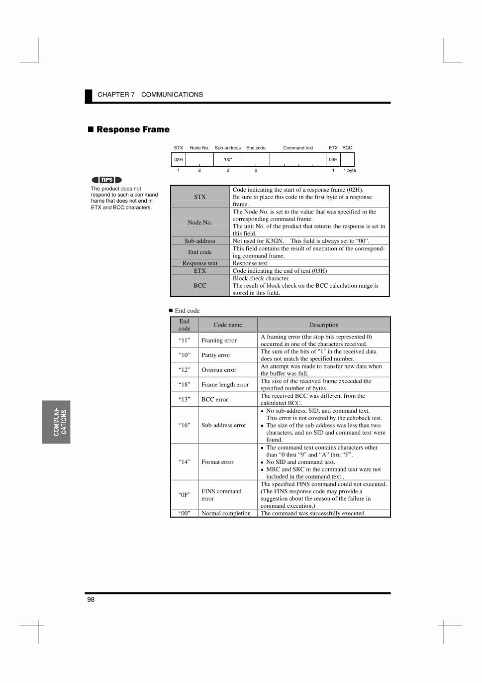
CHAPTER 7 COMMUNICATIONS
98
&20081,�
&$7,216
���#��� ��)�
STXCode indicating the start of a response frame (02H).Be sure to place this code in the first byte of a responseframe.
Node No.
The Node No. is set to the value that was specified in thecorresponding command frame.The unit No. of the product that returns the response is set inthis field.
Sub-address Not used for K3GN. This field is always set to “00”.
End codeThis field contains the result of execution of the correspond-ing command frame.
Response text Response textETX Code indicating the end of text (03H)
BCCBlock check character.The result of block check on the BCC calculation range isstored in this field.
z End code
Endcode
Code name Description
“11” Framing errorA framing error (the stop bits represented 0)occurred in one of the characters received.
“10” Parity errorThe sum of the bits of "1" in the received datadoes not match the specified number.
“12” Overrun errorAn attempt was made to transfer new data whenthe buffer was full.
“18” Frame length errorThe size of the received frame exceeded thespecified number of bytes.
“13” BCC errorThe received BCC was different from thecalculated BCC.
“16” Sub-address error
x No sub-address, SID, and command text.This error is not covered by the echoback test.
x The size of the sub-address was less than twocharacters, and no SID and command text werefound.
“14” Format error
x The command text contains characters otherthan “0 thru “9” and “A” thru “F”.
x No SID and command text.x MRC and SRC in the command text were not
included in the command text..
“0F”FINS commanderror
The specified FINS command could not executed.(The FINS response code may provide asuggestion about the reason of the failure incommand execution.)
“00” Normal completion The command was successfully executed.
The product does notrespond to such a commandframe that does not end inETX and BCC characters.
7,36
STX
02H
Node No. Sub-address
"00"
Command text ETX
03H
BCC
1 2 2 1 1 byte
End code
2

7.3 Structure of Command/Response Text
99
&20081,�
&$7,216
/����%�������$���������! &�� ��:
The command/response text constitutes the main body of a command/responseframe.
The structure of the command/response text is as follows.
The command text consists of MRC (Main Request Code) and SRC (Sub RequestCode) followed by the required data.
The response text consists of MRC and SRC followed by MRES (Main ResponseCode) and SRES (Sub Response Code) and the required data.
If the product fails to execute a specified command, it generates a responseconsisting of MRC/SRC and MRES and SRES only.
z List of services
MRC SRC Service name Description
“01” “01” Read from variable areaThis service reads from the variablearea.
“01” “02” Write to variable areaThis service writes to the variablearea.
“05” “03” Read controller attributeThis service reads the model No. andthe communications buffer size.
“06” “01” Read controller statusThis service reads the run status of thecontroller.
“08” “01” Echoback testThis service carries out the echobacktest.
“30” “05” Operation instructionsThis service carries out forced-zero(cancel) operation, etc.
��� ��%�)�
*��� ���%�)�
MRC
2
SRC
2 bytes
Data
STX
02H
Node No. Sub-address
"00"
SID
"0"
Command text ETX
03H
BCC
STX
02H
Node No. Sub-address
"00"
Command text ETX
03H
BCCEnd code
MRC
2
SRC
2
MRES
2
SRES
2 bytes
Data

CHAPTER 7 COMMUNICATIONS
100
&20081,�
&$7,216
/����-�������3��
A section of memory in the product that holds data to be transmitted is called thevariable area.
The variable area is used for reading of current process values or reading/writingof various parameters.
In contrast, the variable area is not used for operation instructions or reading ofcontroller attributes.
To specify the position of a variable in the variable area, use a variable type andan address.
Append to each variable type an access-size-based address that is expressed in 2-byte hexadecimal code
A variable has an eight-digit value in hexadecimal. A negative variable is ex-pressed in two’s complement. When the current value of a variable is read as����� on the main indicator of the product, for example, its hexadecimal notationis 0000041AH (the decimal point is ignored; 105.0 o 1050 o 0000041AH), andthe variable is read in this form.
The variable area is mapped as follows. The variable type is converted to a 2-byte ASCII code and loaded to the frame. Available variable types are alsoshown below.
Variable type C0: Read-only data including process values and status
Variable type C1: Protect level parameters
Variable type C2: Operation level parameters (OUT set values and remote inputvalues)
Variable type C3: Initial setting, communication setting, and advanced-functionsetting level parameters
0000
0001
0002
0003
0004
0005
0006
0007
0008
0009
000A
000B
000C
000D
000E
000F
0010
0011
0012
0013
0014
0015
0016
0017
0018
0019
001A
001B
001C
001D
C0
C1
C2
C3
Process value,etc.
Protectlevel
Operation level
Initial setting levelCommunication
setting level Advanced-function setting level
Not used
Not used
Not used
0000 0001 0002 0003 001B 001C 001DAddress
C0
C1
C2
C3
Variable type
Variable
K3GN
Variable area
Data reading/writing
Microcomputer
Operation instruction

7.5 Read from Variable Area
101
&20081,�
&$7,216
/�)��!���$����-�������3��
This service reads data from the variable areas.
Command text
Item Description
MRC/SRCSet these items to “01"/"01” ("Read from Variable Area"service).
Variable type Set this item to one among “C0” thru “C3”.Read start address Specify the read start address at this field.Bit position Not used for K3GN. Always set this item to “00”.
No. of elementsSet this item to the quantity of variables that are to be read(up to 10).
Rresponse text
Item Description
MRC/SRCThis field contains the same value (“01"/"01”) as specifiedin the command text.
Response code This field contains the result of execution of the command.Data to be read This field contains the data that is read and to be read.
Response codes
Responsecode
Code name Description
“1001” Command length over The command is too long.“1002” Command length short The command is too short.“1101” Area type error The specified variable type is invalid.
“1103”Start address out-of-range error
The specified start address is outside thevalid range.
“110B” Response length over The No. of elements exceeds 10.
“1100” Parameter errorThe bit position is set to a value other than“00”.
“2203” Operation error EEPROM error“0000” Normal completion The command was successfully executed.
��� �
*��� ��
MRC
"01"
2
SRC
2
"01"
Variabletype
2
Read startaddress
4
Bitposition
2
"00"
No. of elements
4 bytes
MRC
"01"
2
SRC
2
"01"
Response code(MRES/SRES)
4
Data to be read
(No. of elements x 8) bytes
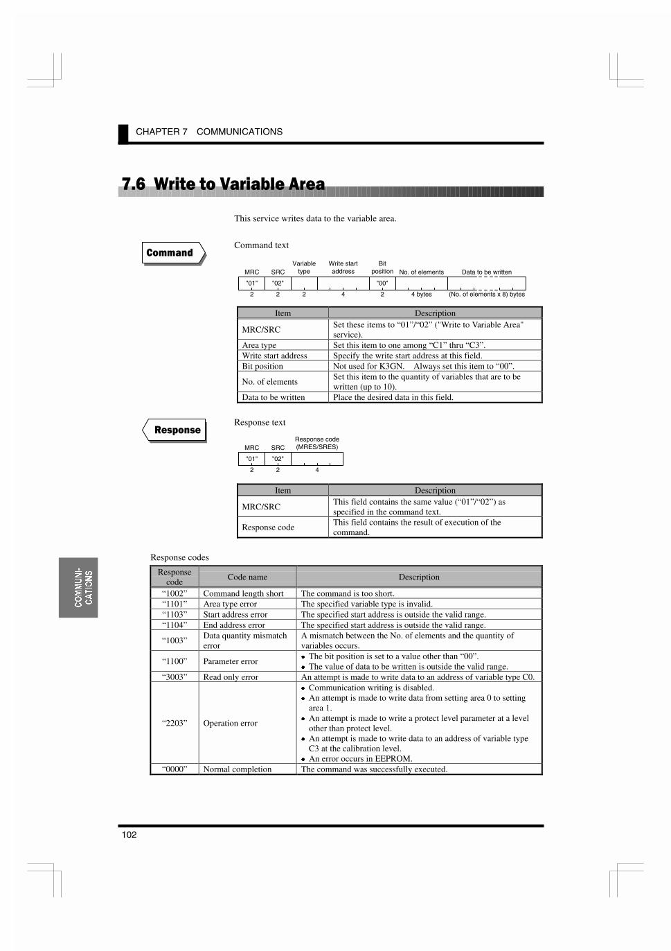
CHAPTER 7 COMMUNICATIONS
102
&20081,�
&$7,216
/�*��.�����-�������3��
This service writes data to the variable area.
Command text
Item Description
MRC/SRCSet these items to “01”/“02” ("Write to Variable Area"service).
Area type Set this item to one among “C1” thru “C3”.Write start address Specify the write start address at this field.Bit position Not used for K3GN. Always set this item to “00”.
No. of elementsSet this item to the quantity of variables that are to bewritten (up to 10).
Data to be written Place the desired data in this field.
Response text
Item Description
MRC/SRCThis field contains the same value (“01”/“02”) asspecified in the command text.
Response codeThis field contains the result of execution of thecommand.
Response codes
Responsecode
Code name Description
“1002” Command length short The command is too short.“1101” Area type error The specified variable type is invalid.“1103” Start address error The specified start address is outside the valid range.“1104” End address error The specified start address is outside the valid range.
“1003”Data quantity mismatcherror
A mismatch between the No. of elements and the quantity ofvariables occurs.
“1100” Parameter error x The bit position is set to a value other than “00”.x The value of data to be written is outside the valid range.
“3003” Read only error An attempt is made to write data to an address of variable type C0.
“2203” Operation error
x Communication writing is disabled.x An attempt is made to write data from setting area 0 to setting
area 1.x An attempt is made to write a protect level parameter at a level
other than protect level.x An attempt is made to write data to an address of variable type
C3 at the calibration level.x An error occurs in EEPROM.
“0000” Normal completion The command was successfully executed.
��� �
*��� ��
MRC
"01"
2
SRC
2
"02"
Response code(MRES/SRES)
4
MRC
"01"
2
SRC
2
"02"
Variabletype
2
Write startaddress
4
Bitposition
2
"00"
Data to be written
(No. of elements x 8) bytes
No. of elements
4 bytes
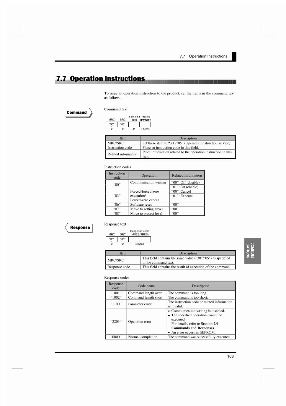
7.7 Operation Instructions
103
&20081,�
&$7,216
/�/���&�������� ������
To issue an operation instruction to the product, set the items in the command textas follows.
Command text
Item DescriptionMRC/SRC Set these item to “30”/”05” (Operation Instruction service).Instruction code Place an instruction code in this field.
Related informationPlace information related to the operation instruction in thisfield.
Instruction codes
Instructioncode
Operation Related information
“00”: Off (disable)“00”
Communication writing“01”: On (enable)“00”: Cancel
“03”Forced-forced-zeroexecution/Forced-zero cancel
“01”: Execute
“06” Software reset “00”“07” Move to setting area 1 “00”“08” Move to protect level “00”
Response text
Item Description
MRC/SRCThis field contains the same value (“30”/"05") as specifiedin the command text.
Response code This field contains the result of execution of the command.
Response codes
Responsecode
Code name Description
“1001” Command length over The command is too long.“1002” Command length short The command is too short.
“1100” Parameter errorThe instruction code or related informationis invalid.
“2203” Operation error
x Communication writing is disabled.x The specified operation cannot be
executed.For details, refer to Section 7.9Commands and Responses.
x An error occurs in EEPROM.“0000” Normal completion The command was successfully executed.
��� �
*��� ��
MRC
"30"
2
SRC
2
"05"
Response code(MRES/SRES)
4 bytes
MRC
"30"
2
SRC
2
"05"
,QVWUXFWLRQ
FRGH
2
5HODWHG
LQIRUPDWLRQ
2 bytes

CHAPTER 7 COMMUNICATIONS
104
&20081,�
&$7,216
/�1��%����3��
The K3GN series of products can assume two states that are refereed to as settingarea 0 and setting area 1 in this manual.
In setting area 0, the product is carrying out a measurement.
In this state, you can therefore perform such operations that are permitted onlyduring measuring, or that cause no trouble even if a measurement is in progress.These operations include “process value reading”, “parameter writing” and“forced-zero execution”.
On the contrary, this state prohibits such operations that exert an effect onmeasurement in progress, including “parameter writing at the initial setting level”(parameter reading is always allowed).
In setting area 1, measurement is suspended.
In this state, you can therefore perform such operations that are not allowed insetting area 0. These operations include “parameter writing at the initial setting,communication setting, and advanced-function setting levels”.
At power-on, the product is in settingarea 0. To move to setting area 1, usethe “move-to-setting area 1” instruc-tion. To return to setting area 0,power the product off and on again, oruse the “software reset” instruction.
The figure on the right shows thesetting areas and the levels containedin each setting area.
A transition to the initial setting levelby key operation implies a transitionfrom setting area 0 to setting area 1.This enables the host PC to operate theproduct in setting area 1.
A transition to setting area 1 by remotecontrol from the host PC causes thelevel indicator on the front panel toindicate the product is at the initialsetting level. To return to the opera-tion level, use the . key.
Protect level
Adjustmentlevel
Calibrationlevel
Setting area 0
Setting area 1
Operation level
Initial settinglevel
Communicationsetting level
Advanced-function setting
level
*
* At the calibration level, the product refuses controlfrom the host PC.
Setting area 0 Setting area 1
Power ON
"Move-to-settingarea 1" instruction
"Software reset" instruction
Measurementin progress
Measurementsuspended
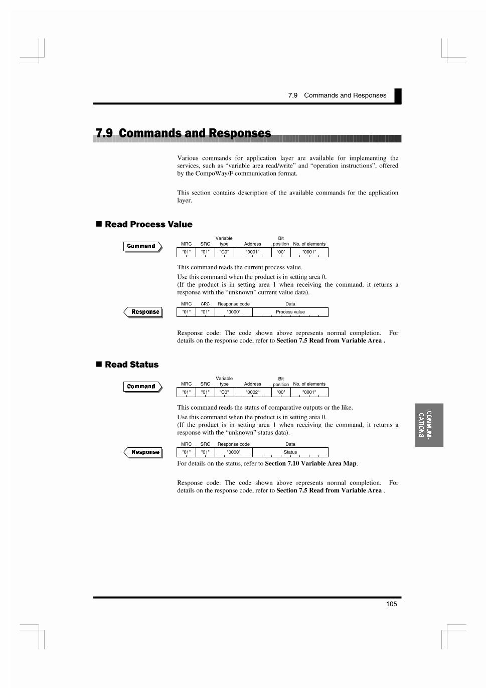
7.9 Commands and Responses
105
&20081,�
&$7,216
/�2��������� �����! &��
Various commands for application layer are available for implementing theservices, such as “variable area read/write” and “operation instructions”, offeredby the CompoWay/F communication format.
This section contains description of the available commands for the applicationlayer.
���� ������ +����
This command reads the current process value.
Use this command when the product is in setting area 0.(If the product is in setting area 1 when receiving the command, it returns aresponse with the “unknown” current value data).
Response code: The code shown above represents normal completion. Fordetails on the response code, refer to Section 7.5 Read from Variable Area .
���� ������
This command reads the status of comparative outputs or the like.
Use this command when the product is in setting area 0.(If the product is in setting area 1 when receiving the command, it returns aresponse with the “unknown” status data).
For details on the status, refer to Section 7.10 Variable Area Map.
Response code: The code shown above represents normal completion. Fordetails on the response code, refer to Section 7.5 Read from Variable Area .
&RPPDQG
5HVSRQVH
&RPPDQG
5HVSRQVH
MRC
"01"
SRC
"01"
Variabletype
"C0" "0001"
AddressBit
position
"00" "0001"
No. of elements
Process value
MRC
"01"
ª©�
"01" "0000"
Response code Data
MRC
"01"
SRC
"01"
Variabletype
"C0" "0002"
AddressBit
position
"00" "0001"
No. of elements
Status
MRC
"01"
SRC
"01" "0000"
Response code Data

CHAPTER 7 COMMUNICATIONS
106
&20081,�
&$7,216
���� ��)��� �#�� +����
This command supplies an input value to the product that is used as a digital datadisplay for PLC/PC.
Use this command when the product is in setting area 0.(If the product is in setting area 1 when receiving the command, no change occurson the main indicator as measurement is suspended).
Before issuing the command, use an operation instruction to enable“communication writing”.
Response code: The code shown above represents normal completion. Fordetails on the response code, refer to Section 7.6 Write to Variable Area .
���� ��� ��� +����
Address Parameter“0001” OUT1 value“0002” OUT1 upper-limit value“0003” OUT1 lower-limit value“0004” OUT2 value“0005” OUT2 upper-limit value“0006” OUT2 lower-limit value
This command reads an OUT set value.
(Even if the type of the OUT set value is “upper” or “lower”, OUT upper andlower-limit values can be read. Even if the type of the OUT set value is“upper/lower”, an OUT set value can be read).
Response code: The code shown above represents normal completion. Fordetails on the response code, refer to Section 7.5 Read from Variable Area .
&RPPDQG
5HVSRQVH
&RPPDQG
5HVSRQVH
MRC
"01"
SRC
"02"
Variabletype
"C2" "0000"
AddressBit
position
"00" "0001"
No. of elements
Remote input value
Data
MRC
"01"
SRC
"02" "0000"
Response code
MRC
"01"
SRC
"01"
Variabletype
"C2"
AddressBit
position
"00" "0001"
No. of elements
Threshold
MRC
"01"
SRC
"01" "0000"
Response code Data

7.9 Commands and Responses
107
&20081,�
&$7,216
���� ��� ��� +����
Address Parameter“0001” OUT1 value“0002” OUT1 upper-limit value“0003” OUT1 lower-limit value“0004” OUT2 value“0005” OUT2 upper-limit value“0006” OUT2 lower-limit value
This command writes an OUT set value.
It can be used when the product is in either setting area 0 or 1.
(Even if the type of the OUT set value is “upper” or “lower”, OUT upper andlower-limit values can be written. Doing so exerts no effect on comparativeoutput. Likewise, even if the type of the OUT set value is “upper/lower”, anOUT set value can be written).
If you want to write both OUT1 and OUT2 values at a time, use block access tothe variable area. For details, refer to the tip shown in Section 7.10 VariableArea Map.
Before issuing the command, use an operation instruction to enable“communication writing”.
Response code: The code shown above represents normal completion. Fordetails on the response code, refer to Section 7.6 Write to Variable Area .
���� ���)���
Variable type Address Parameter“C1” “0000” to “0003” Protect level parameters
“0000” to “000B” Initial setting level parameters“000C” to “0010” Communication setting level parameters“C3”“0011” to “001D” Advanced-function setting level parameters
This command reads a parameter.
For details on how to specify the variable type and the address, refer to Section7.10 Variable Area Map.
This command can be used when the product is in either setting area 0 or 1.
(“Analog range”, “input pulse frequency”, “scaling input values 1 and 2”, “scalingdisplay values 1 and 2”, “scaling input value”, and “scaling display value” can beread, irrespective of input type setting).
Response code: The code shown above represents normal completion. Fordetails on the response code, refer to Section 7.5 Read from Variable Area .
&RPPDQG
5HVSRQVH
&RPPDQG
5HVSRQVH
MRC
"01"
SRC
"02" "0000"
Response code
MRC
"01"
SRC
"01"
Variabletype Address
Bitposition
"00" "0001"
No. of elements
Parameter
MRC
"01"
SRC
"01" "0000"
Response code Data
MRC
"01"
SRC
"02" "C2"
Address
"00" "0001"
No. of elements
OUT set value
Data

CHAPTER 7 COMMUNICATIONS
108
&20081,�
&$7,216
���� ������ 1� �� ���)���
Address Parameter“0000” Operation/adjustment lockouts“0001” Initial setting/communication lockouts“0002” Setting change lockout“0003” Forced-zero lockout
This command writes a protect level parameter.
Use this command when the product is in setting area 0. If the product is insetting area 1 when receiving the command, it returns an error.
Before issuing the command, use operation instructions to enable “writing” and toenter the protect level.
Response code: The code shown above represents normal completion. Fordetails on the response code, refer to Section 7.6 Write to Variable Area .
���� ���)��� 9������ ��� %:
Address Parameter“0000” to “000B” Initial setting level parameters“000C” to “0010” Communication setting level parameters“0011” to “001D” Advanced-function setting level parameters
This command writes an initial setting level parameter, a communication settinglevel parameter, or an advanced-function setting level parameter.
For detains on addressing, refer to Section 7.10 Variable Area Map.
Use this command when the product is in setting area 1. If the product is insetting area 0 when receiving the command, it returns an error.
Before issuing the command, use operation instructions to enable “communicationwriting” and to enter setting area 1.
Response code: The code shown above represents normal completion. Fordetails on the response code, refer to Section 7.6 Write to Variable Area .
&RPPDQG
5HVSRQVH
&RPPDQG
5HVSRQVH
MRC
"01"
SRC
"02"
Variabletype
"C1"
AddressBit
position
"00" "0001"
No. of elements
Protect level parameter
Data
MRC
"01"
SRC
"02" "0000"
Response code
MRC
"01"
SRC
"02"
Variabletype
"C3"
AddressBit
position
"00" "0001"
No. of elements
Parameter (setting area 1)
Data
MRC
"01"
SRC
"02" "0000"
Response code

7.9 Commands and Responses
109
&20081,�
&$7,216
��))������� �����
Related information Description“00” Communication writing disable“01” Communication writing enable
This command enables/disables communication writing.
It rewrites the value of the adjustment level parameter “communication writing”.
If communication writing is disabled, operation instructions for parameterrewriting, forced-zero execution/forced-zero cancel and the like are rejected.
This command can be used when the product is in either setting area 0 or 1.
Response code: The code shown above represents normal completion. Fordetails on the response code, refer to Section 7.7 Operation Instructions.
�����*,�� �;������-�����
Forced-zero Description“00” Forced-zero cancel“01” Forced-forced-zero execution
This command executes/cancels the forced-zero operation.
Use this command when the product is in setting area 0. If product is in settingarea 1 when receiving the command, it returns an error.
If the product has no measured value, suffers input anomalies, or encounters a“display range over” error when receiving the command, it returns an error. Ifthe event input is used for “process value hold” when receiving the command, italso returns an error.
Before issuing the command, use an operation instruction to enable“communication writing”.
Response code: The code shown above represents normal completion. Fordetails on the response code, refer to Section 7.7 Operation Instructions.
&RPPDQG
5HVSRQVH
&RPPDQG
5HVSRQVH
MRC
"30"
SRC
"05" "0000"
Response code
MRC
"30"
SRC
"05" "0000"
Response code
MRC
"30"
SRC
"05"
Instructioncode
"00"
Relatedinformation
MRC
"30"
SRC
"05"
Instructioncode
"03"
Relatedinformation

CHAPTER 7 COMMUNICATIONS
110
&20081,�
&$7,216
����"�� �����
This command triggers a software reset, which returns the product to its initialstate when it was powered on.
It can be used when the product is in either setting area 0 or 1.
Before issuing the command, use an operation instruction to enable“communication writing”.
The software reset command does not require the product to return a response.
(� � �� ������ ��� %
This command provides a transition of the product to setting area 1.
Use this command in setting area 0. If the product is in setting area 1 whenreceiving the command, the command is ignored.
If the set value of the “initial setting/communication lockouts” parameter is 2indicating “move to initial setting level” and “move to communication settinglevel” are disabled (refer to Section 5.7 Key Protect Setting) when the productreceives the command, the product returns an error.
Before issuing this command, use an operation instruction to enable“communication writing”.
Response code: The code shown above represents normal completion. Fordetails on the response code, refer to Section 7.7 Operation Instructions.
(� � �� ������ 1� ��
This command moves the product to the protect level.
Use this command when the product is in setting area 0. If the product is insetting area 1 when receiving the command, it returns an error.
Before issuing the command, use an operation instruction to enable“communication writing”.
Response code: The code shown above represents normal completion. Fordetails on the response code, refer to Section 7.7 Operation Instructions.
&RPPDQG
5HVSRQVH
&RPPDQG
5HVSRQVH
&RPPDQG
5HVSRQVH
(Non)
MRC
"30"
SRC
"05" "0000"
Response code
MRC
"30"
SRC
"05" "0000"
Response code
MRC
"30"
SRC
"05"
Instructioncode
"07"
Relatedinformation
"00"
MRC
"30"
SRC
"05"
Instructioncode
"08"
Relatedinformation
"00"
MRC
"30"
SRC
"05"
Instructioncode
"06"
Relatedinformation
"00"
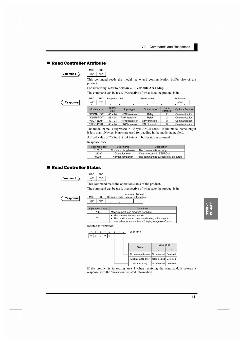
7.9 Commands and Responses
111
&20081,�
&$7,216
���� ������� ��������
This command reads the model name and communication buffer size of theproduct.
For addressing, refer to Section 7.10 Variable Area Map.
The command can be used, irrespective of what state the product is in.
Model name Buffersize Input type Output type No. of
contacts Optional feature
“K3GN-NDC” 48 × 24 NPN transistor Relay 2 Communication“K3GN-PDC” 48 × 24 PNP transistor Relay 2 Communication“K3GN-NDT1” 48 × 24 NPN transistor NPN transistor 3 Communication“K3GN-PDT2” 48 × 24 PNP transistor PNP transistor 3 Communication
The model name is expressed in 10-byte ASCII code. If the model name lengthis less than 10 bytes, blanks are used for padding in the model name field.
A fixed value of “0068H” (104 bytes) in buffer size is returned.
Response code
Response code Error name Description“1001” Command length over The command is too long.“2203” Operation error An error occurs in EEPROM.“0000” Normal completion The command is successfully executed.
���� ������� ������
This command reads the operation status of the product.
The command can be used, irrespective of what state the product is in.
Operation status Description“00” Measurement is in progress normally.
“01”x Measurement is suspended.x The product has no measured value, suffers input
anomalies, or encounters a “display range over” error.
Related information
If the product is in setting area 1 when receiving the command, it returns aresponse with the “unknown” related information.
&RPPDQG
5HVSRQVH
&RPPDQG
5HVSRQVH
MRC
"05"
SRC
"03"
MRC
"06"
SRC
"01"
MRC
"06"
SRC
"01"
Response codeOperation
statusRelated
information
00 0 0 0
01234567 Bit position
No measured value
Display range over
Input anomaly
Not detected Detected
Not detected Detected
Not detected Detected
Status0 1
Value of bit
MRC
"05"
SRC
"03"
Response code Model name
"0068"
Buffer size
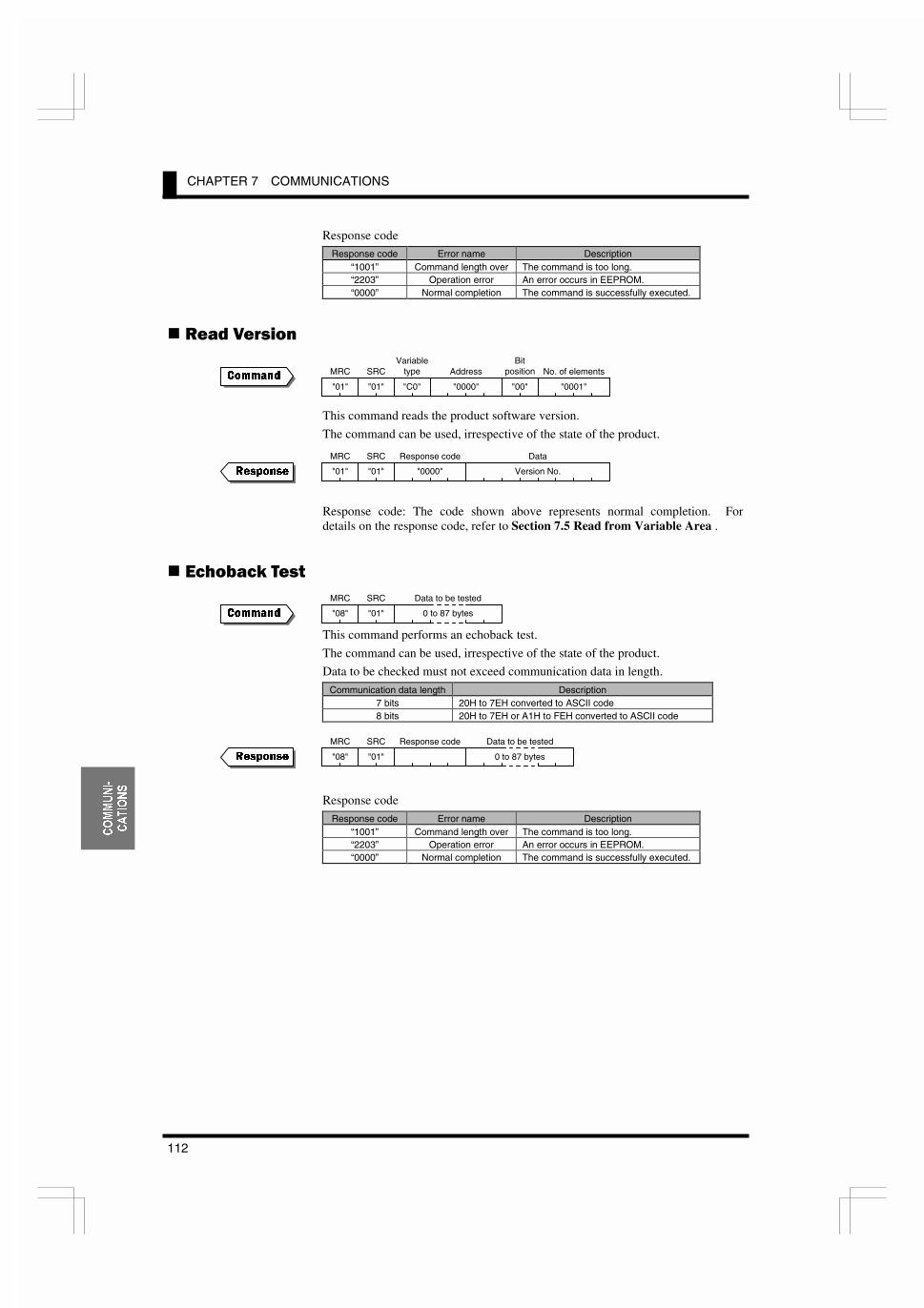
CHAPTER 7 COMMUNICATIONS
112
&20081,�
&$7,216
Response codeResponse code Error name Description
“1001” Command length over The command is too long.“2203” Operation error An error occurs in EEPROM.“0000” Normal completion The command is successfully executed.
���� +����
This command reads the product software version.
The command can be used, irrespective of the state of the product.
Response code: The code shown above represents normal completion. Fordetails on the response code, refer to Section 7.5 Read from Variable Area .
��!����/ ����
This command performs an echoback test.
The command can be used, irrespective of the state of the product.
Data to be checked must not exceed communication data in length.
Communication data length Description7 bits 20H to 7EH converted to ASCII code8 bits 20H to 7EH or A1H to FEH converted to ASCII code
Response code
Response code Error name Description“1001” Command length over The command is too long.“2203” Operation error An error occurs in EEPROM.“0000” Normal completion The command is successfully executed.
&RPPDQG
5HVSRQVH
&RPPDQG
5HVSRQVH
MRC
"01"
SRC
"01"
Variabletype
"C0" "0000"
AddressBit
position
"00" "0001"
No. of elements
Version No.
MRC
"01"
SRC
"01" "0000"
Response code Data
MRC
"08"
SRC
"01"
Data to be tested
0 to 87 bytes
MRC
"08"
SRC
"01"
Response code Data to be tested
0 to 87 bytes
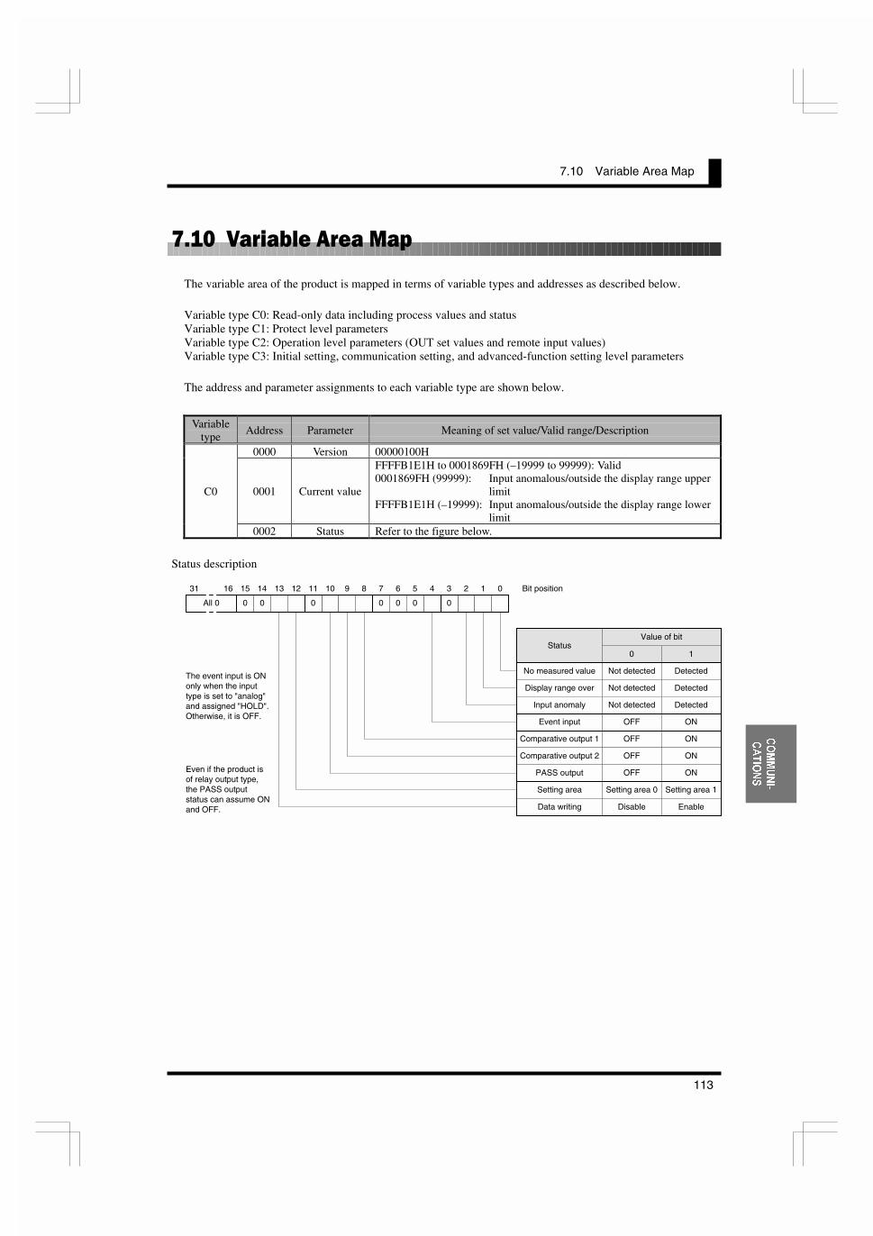
7.10 Variable Area Map
113
&20081,�
&$7,216
/��4��-�������3�����&
The variable area of the product is mapped in terms of variable types and addresses as described below.
Variable type C0: Read-only data including process values and statusVariable type C1: Protect level parametersVariable type C2: Operation level parameters (OUT set values and remote input values)Variable type C3: Initial setting, communication setting, and advanced-function setting level parameters
The address and parameter assignments to each variable type are shown below.
Variabletype
Address Parameter Meaning of set value/Valid range/Description
0000 Version 00000100H
0001 Current value
FFFFB1E1H to 0001869FH (–19999 to 99999): Valid0001869FH (99999): Input anomalous/outside the display range upper
limitFFFFB1E1H (–19999): Input anomalous/outside the display range lower
limit
C0
0002 Status Refer to the figure below.
Status description
0 0 0 0 0 0 0
01234567891011121314151631
All 0
Bit position
The event input is ONonly when the inputtype is set to "analog"and assigned "HOLD".Otherwise, it is OFF.
Even if the product isof relay output type,the PASS outputstatus can assume ONand OFF.
No measured value
Display range over
Input anomaly
Event input
Comparative output 1
Comparative output 2
PASS output
Setting area
Data writing
Not detected Detected
Not detected Detected
Not detected Detected
OFF ON
OFF ON
OFF ON
OFF ON
Setting area 0 Setting area 1
Disable Enable
Status0 1
Value of bit

CHAPTER 7 COMMUNICATIONS
114
&20081,�
&$7,216
Variabletype
Address Parameter Meaning of set value/Valid range/Description
0000Operation/adjustmentlockouts
00000000H (0): No restriction at the operation/adjustment levels00000001H (1): “Move to adjustment level” is disabled.00000002H (2): Only the process value can be displayed.Access via communications is enabled, irrespective of the value ofthis parameter.
0001Initial setting/
communicationlockouts
00000000H (0): “Move to initial setting/communicationsetting/advanced-function setting levels” is enabled.
00000001H (1): “Move to advanced-function setting level” isdisabled.
00000002H (2): “Move to initial setting/communication settinglevels” is disabled.
Access via communications is enabled, irrespective of the value ofthis parameter.
0002Setting change
lockout
00000000H (0): OFF: A parameter change by key operation isenabled.
00000001H (1): ON: A parameter change by key operation isdisabled.
Communication writing is enabled, irrespective of the value of thisparameter.
C1
0003Forced-zero
lockout
00000000H (0): OFF: Forced-zero execution/forced-zero cancel isenabled.
00000001H (1): ON: Forced-zero execution/forced-zero cancel isdisabled.
Communication writing is enabled, irrespective of the value of thisparameter.
0000Remote input
value
FFFFB1E1H to 0001869FH (–19999 to 99999)An input value is written to this variable when the product is used as adigital data display for PLC/PC.
0001 OUT1 value FFFFB1E1H to 0001869FH (–19999 to 99999)
0002OUT1 upper-limit
valueFFFFB1E1H to 0001869FH (–19999 to 99999)
0003OUT1 lower-limit
valueFFFFB1E1H to 0001869FH (–19999 to 99999)
0004 OUT2 value FFFFB1E1H to 0001869FH (–19999 to 99999)
0005OUT2 upper-limit
valueFFFFB1E1H to 0001869FH (–19999 to 99999)
C2
0006OUT2 lower-limit
valueFFFFB1E1H to 0001869FH (–19999 to 99999)
Variabletype
Address Parameter Meaning of set value/Valid range/Description
0000 Input type00000000H (0): Analog00000001H (1): Pulse00000002H (2): Remote
0001 Analog range
00000000H (0): 4 to 20 mA/0 to 20 mA00000001H (1): 1 to 5 V/0 to 5 V00000002H (2): ±5 V00000003H (3): ±10 V
0002 Input pulse frequency00000000H (0): 30 Hz00000001H (1): 5 kHz
0003 Scaling input value 1 FFFFB1E1H to 0001869FH (–19999 to 99999)0004 Scaling display value 1 FFFFB1E1H to 0001869FH (–19999 to 99999)0005 Scaling input value 2 FFFFB1E1H to 0001869FH (–19999 to 99999)0006 Scaling display value 2 FFFFB1E1H to 0001869FH (–19999 to 99999)
0007 Scaling input valueFFFFB1E1H to 0001869FH (–19999 to 99999):
When the input type is set to "pulse"
C3
0008 Scaling display valueFFFFB1E1H to 0001869FH (–19999 to 99999):
When the input type is set to "pulse"

7.10 Variable Area Map
115
&20081,�
&$7,216
Variabletype
Address Parameter Meaning of set value/Valid range/Description
0009 Decimal point position
00000000H (0): �����
00000001H (1): ������
00000002H (2): ������
00000003H (3): ������
00000004H (4): ������
000A OUT1 type00000000H (0): Upper-limit action00000001H (1): Lower-limit action00000002H (2): Outside-the-range action
000B OUT2 type00000000H (0): Upper-limit action00000001H (1): Lower-limit action00000002H (2): Outside-the-range action
000C Communication unit No. 00000000H ~ 00000063H (0 ~ 99)
000D Baud rate
00000000H (0): 1.2 kbps00000001H (1): 2.4 kbps00000002H (2): 4.8 kbps00000003H (3): 9.6 kbps00000004H (4): 19.2 kbps
000E Word length00000000H (0): 7 bits00000001H (1): 8 bits
000F Stop bit length00000000H (0): 1 bit00000001H (1): 2 bits
0010 Parity bits00000000H (0): Non00000001H (1): Even00000002H (2): Odd
0011No. of measurements
for averaging
00000000H (0): OFF00000001H (1): 200000002H (2): 400000003H (3): 8
0012 Event input function00000000H (0): HOLD00000001H (1): ZERO
0013 OUT1 hysteresis 00000000H to 0000270FH (0 to 9999)0014 OUT2 hysteresis 00000000H to 0000270FH (0 to 9999)0015 Auto-zero time 00000000H to 000000C7H (0.0 to 19.9)0016 Startup compensation time 00000000H to 000003E7H (0.0 to 99.9)0017
to 0019(Not assigned) 00000000H (0)
001A Display color change
00000000H (0): Green to red00000001H (1): Always green00000002H (2): Red to green00000003H (3): Always red
001B Display auto-return time 00000000H to 00000063H (0 to 99)001C Move-to-protect-level time 00000000H to 00000013H (0 to 19)
C3
001D Send waiting time 00000000H to 00000063H (0 to 99)
Block access to the variablearea
A number of contiguouslyaddressed variables of thesame type in the variable areacan be accessed at a time.For example, you can read thecurrent value and the statussimultaneously by setting theread start address to theaddress of the current valueand setting the No. of elementsto 2.
Such an access method iscalled “block access”.
7,36
Start
Variable area readcommand issued(for current value)
Variable area readcommand issued
(for status)
End
Variable type: C0Address 0001No. of element: 0001
Variable type: C0Address: 0002No. of element: 0001
Separate access
Start
Variable area readcommand issued
End
Variable type: C0Address: 0001No. of element: 0002
Block access

CHAPTER 7 COMMUNICATIONS
116
&20081,�
&$7,216
/����������������� �����������;
This section describes the control flow of comminations between the product andthe host PC. Information in this section will help you make up a program forcontrolling the product.
��))������� ������
Communication reading is performed according to the following flow. Itinvolves no response from the product to the host PC.
Commands applicable to this flow are shown below.
Applicable commandsRead process value
Read statusRead OUT set value
Read parameterRead controller attribute
Read controller statusRead versionEchoback test
Start
Wait state
Data read commandWait state
Data read
Wait stateEnd
Host PC K3GN

7.11 Communications Control Flow
117
&20081,�
&$7,216
��))������� ����� 9������ ��� <:
When the product is in setting area 0, communication writing is performedaccording the following flow.
Commands applicable to this flow are as follow.
Applicable commandsWrite remote input value
Write OUT set value
Remote input values would often be written with a high frequency.You should therefore keep “communication writing” in “enable” state and thencontinuously write input values. Doing so will shorten the time forcommunication writing.
Start
Wait state
Write Remote InputValue Command Wait state
NORMAL RESPONSE
Wait stateEnd
Host PC K3GN
It is assumed that communicationwriting has been enabled.
Start
Wait state
Communication writinginstruction (Communication
writing enabled)Wait state
NORMAL RESPONSE
Wait state
End
Host PC K3GN
Parameter read command
Wait stateNORMAL RESPONSE
Communication writinginstruction (Communication
writing disabled)Wait state
NORMAL RESPONSEWait state
Wait state
�����=
T
"CMW" is illuminated.
�����=
T
"CMW" goes off.

CHAPTER 7 COMMUNICATIONS
118
&20081,�
&$7,216
������ 1� �� ���)��� �����
A protect level parameter is written according to the following flow.
The following command is applicable to this flow.
Applicable commandWrite protect level parameter
Start
Wait state
Communication writinginstruction (Communication
writing enabled) Wait state
NORMAL RESPONSE
Wait state
End
Host PC K3GN
Parameter write command
Wait state
NORMAL RESPONSE
Operation instruction forsoftware reset
Wait state
NORMAL RESPONSE
Wait state
�����=
T
"CMW" is illuminated.
�����=
T
"CMW" goes off.
Operation instruction to moveto protect level
Wait state �����G
T
"G" is displayed.
Software reset
The first parameter at theprotect level is displayed.
�����=
T
Communication writinginstruction (Communication
writing disabled)
Wait 2 seconds untilthe product is soft-
reset
Wait state
Wait state
NORMAL RESPONSE
Wait state

7.11 Communications Control Flow
119
&20081,�
&$7,216
���)��� ����� 9������ ��� %:
When the product is in setting area 1, a parameter is written according to thefollowing flow.
The following command is applicable to this flow.
Applicable commandWrite parameter (setting area 1)
Start
Wait state
Communication writinginstruction (Communication
writing enabled)Wait state
NORMAL RESPONSE
Wait state
End
Host PC K3GN
Parameter write command
Wait state
NORMAL RESPONSE
Operation instruction forsoftware reset
Wait state
NORMAL RESPONSE
Wait state
�����=
T
"CMW" is illuminated.
�����=
T
"CMW" goes off.
Action instruction to move tosetting area 1
Wait state �����J
T
"�" is displayed.
Software reset
The first parameter atthe initial setting levelis displayed.
�����=
T
Communication writinginstruction (Communication
writing disabled)
Wait 2 seconds untilthe product is soft-
reset
Wait state
Wait state
NORMAL RESPONSE
Wait state

CHAPTER 7 COMMUNICATIONS
120
&20081,�
&$7,216
�#����� ��������An operation instruction is performed according to the following flow.
Commands applicable to this flow are shown below.
Applicable commandsForced-forced-zero execution/cancel
Move to setting area 1Move to protect level
Start
Wait state
Communication writinginstruction (Communication
writing enabled) Wait state
NORMAL RESPONSE
Wait state
End
Host PC K3GN
Instruction for specified action
Wait stateNORMAL RESPONSE
Communication writinginstruction (Communication
writing disabled)Wait state
NORMAL RESPONSEWait state
Wait state
�����=
T
"CMW" is illuminated.
�����=
T
"CMW" goes off.

7.12 Programming Example
121
&20081,�
&$7,216
/�����������������7:��&�
�== .����The section shows a programming example where a response from the product isdisplayed on the screen on the host PC when a command is entered from thekeyboard.
This program is created with N88 BASIC.
���� �������������������������������������������������������
���� 352*5$0� .�*1 &RPPXQLFDWLRQ 6DPSOH 3URJUDP�&RPSR:D\�)�
���� 9(56,21�����
���� �&�&RS\ULJKW 20521 &RUSRUDWLRQ ����
���� $OO 5LJKWV 5HVHUYHG
���� ������������������������������������������������������
����
���� %DXG UDWH VHWWLQJ �3$5,7< (9(1�'$7$ ��6723 �� ³
���� &20 SRUW VHWWLQJV
���� 23(1 ³&20�(��´ $6 ��
����
���� 5(3($7
����
���� 7UDQVPLVVLRQ SURFHVVLQJ
����
���� ��������6' LQSXW����������
���� ,1387 ³6(1' '$7$�´�6(1'�
����
���� ��������,I QRW LQSXW� JR WR HQG SURFHVVLQJ���������
���� ³,) 6(1'� ³³ 7+(1 (;,7
����
���� �������%&& FDOFXODWLRQ��������
���� %&& �
���� 6(1'� 6(1'��&+5����
���� )25 , � 72 /(1�6(1'��
���� ³ %&& %&& ;25 $6&�0,'��6(1'��,����
���� 1(;7 ,
���� %&&� &+5��%&&�
����
���� ������7UDQVPLVVLRQ����������
���� 6'$7$� &+5�����6(1'��%&&�
���� 35,17 ���6'$7$��
����
���� 5HFHSWLRQ SURFHVVLQJ
����
���� 5'$7$� ³³
���� 7,0(287 �
���� /223
���� �������1R�UHVSRQVH GHWHFWLRQ�������
���� 7,0(287 7,0(287��
���� ,) 7,0(287 ! ���� 7+(1 5(63� ³1R 5HVSRQVH´�*272 5(1'
���� ,) /2&��� � 7+(1 /223
����
���� �����(QGLQJ FKDUDFWHU LGHQWLILFDWLRQ �LI QRW HQGLQJ FKDUDFWHU�
FRQWLQXH UHDGLQJ�
���� 5'$7$� 5'$7$��,1387��/2&�������
���� ,) /(1�5'$7$�� � � 7+(1 /223
���� ,) 0,'��5'$7$��/(1�5'$7$������� �! &+5���� 7+(1 /223
���� 5(63� 0,'��5'$7$����/(1�5'$7$�����
���� 5(1'
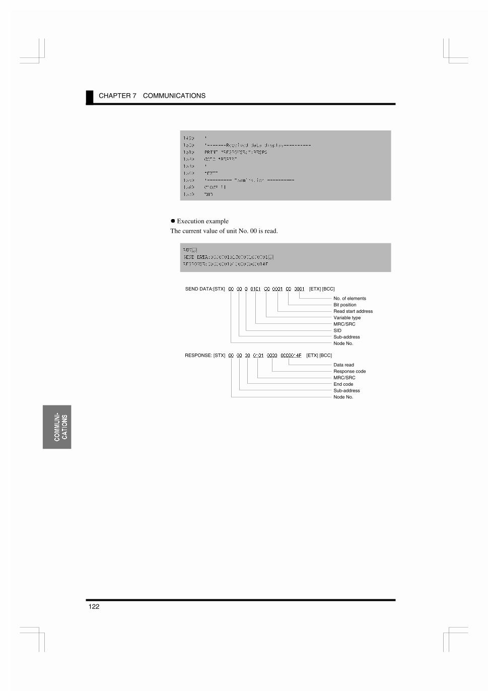
CHAPTER 7 COMMUNICATIONS
122
&20081,�
&$7,216
����
���� �������5HFHLYHG GDWD GLVSOD\����������
���� 35,17 ³5(63216(�´�5(63�
���� *272 5(3($7
����
���� (;,7
���� 7HUPLQDWLRQ
���� &/26( ��
���� (1'
z Execution example
The current value of unit No. 00 is read.
581
6(1' '$7$����������&�����������
5(63216(����������������������)
SEND DATA:[STX] 00 00 0 0101 C0 0001 00 0001 [ETX] [BCC]
No. of elementsBit positionRead start addressVariable typeMRC/SRCSIDSub-addressNode No.
RESPONSE: [STX] 00 00 00 0101 0000 0000014F [ETX] [BCC]
Data readResponse codeMRC/SRCEnd codeSub-addressNode No.
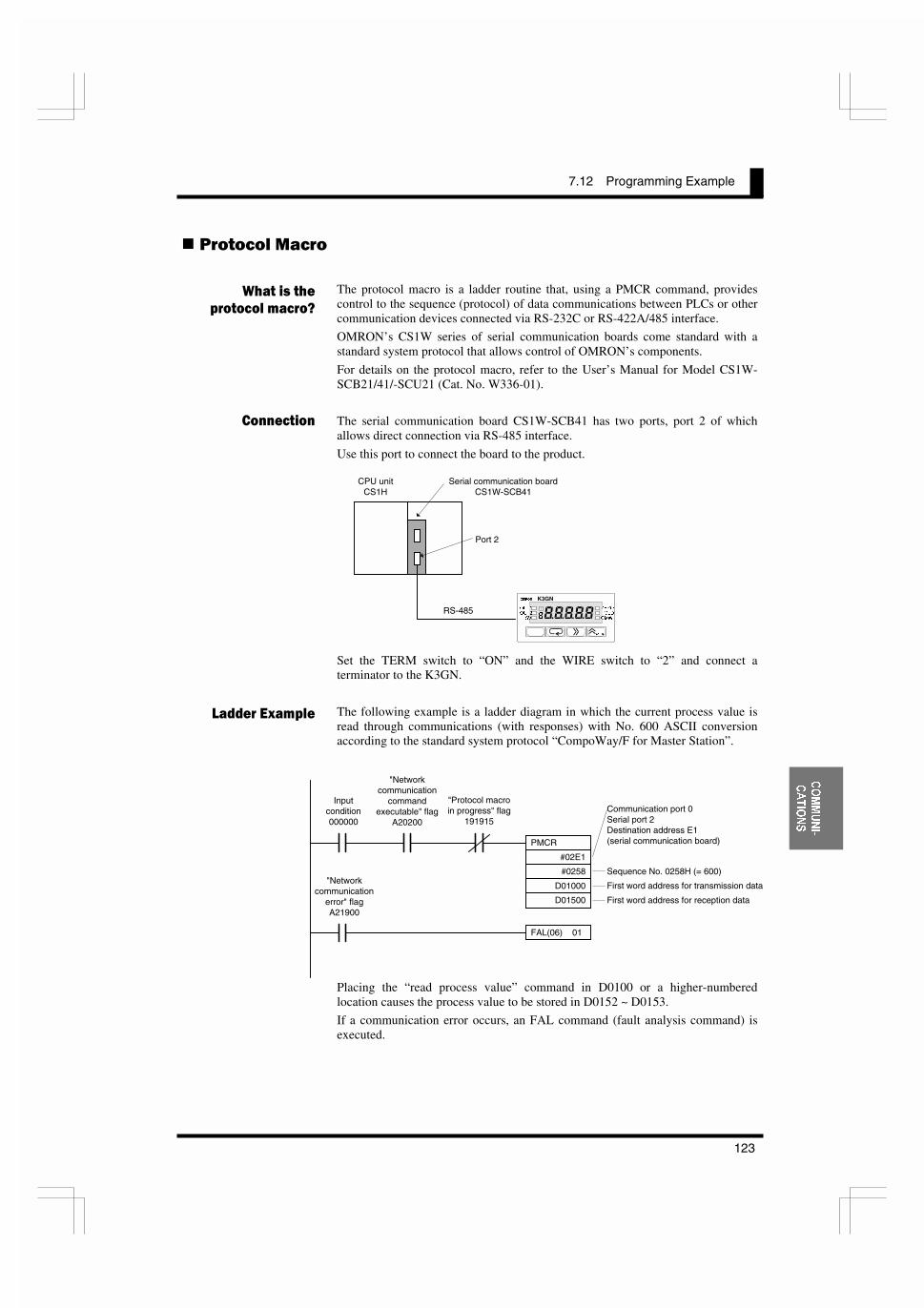
7.12 Programming Example
123
&20081,�
&$7,216
������� (���
The protocol macro is a ladder routine that, using a PMCR command, providescontrol to the sequence (protocol) of data communications between PLCs or othercommunication devices connected via RS-232C or RS-422A/485 interface.
OMRON’s CS1W series of serial communication boards come standard with astandard system protocol that allows control of OMRON’s components.
For details on the protocol macro, refer to the User’s Manual for Model CS1W-SCB21/41/-SCU21 (Cat. No. W336-01).
The serial communication board CS1W-SCB41 has two ports, port 2 of whichallows direct connection via RS-485 interface.
Use this port to connect the board to the product.
Set the TERM switch to “ON” and the WIRE switch to “2” and connect aterminator to the K3GN.
The following example is a ladder diagram in which the current process value isread through communications (with responses) with No. 600 ASCII conversionaccording to the standard system protocol “CompoWay/F for Master Station”.
Placing the “read process value” command in D0100 or a higher-numberedlocation causes the process value to be stored in D0152 ~ D0153.
If a communication error occurs, an FAL command (fault analysis command) isexecuted.
�����������
����������+
����
!������,)�����
CPU unitCS1H
Serial communication boardCS1W-SCB41
Port 2
RS-485
�=(52
������
T
����� K3GN
287�
287�
69
=(52
+2/'
&0:
PMCR
#02E1
#0258
D01000
D01500
Inputcondition000000
"Networkcommunication
commandexecutable" flag
A20200
"Protocol macroin progress" flag
191915Communication port 0Serial port 2Destination address E1(serial communication board)
Sequence No. 0258H (= 600)
First word address for transmission data
First word address for reception data
FAL(06) 01
"Networkcommunication
error" flagA21900

CHAPTER 7 COMMUNICATIONS
124
&20081,�
&$7,216
z Data transmission word assignment
z Data reception word assignment
0007
0001
0101
0010
C000
0100
0001
No. of transmission words (D01000 ~ D01006)
Node No. of K3GN: 1
CompoWay/F command: Variable area read
No. of bytes transmitted: 16
Variable type, read start address, bit position,No. of elements
D01000
D01001
D01002
D01003
D01004
D01005
D01006
MRC
"01"
SRC
"01"
Variabletype
"C0" "0001"
AddressBit
position
"00" "0001"
No. of elements
"0"
SIDSub-
address
"00"
NodeNo.
"01"02H
STX
03H
ETX BCC
0004 No. of reception words (D01500 to D01503)
Response code
D01500
D01501
D01502
D01503Current process value
Process value
MRC
"01"
SRC
"01"
Response code Data
03H
ETX BCCEndcode
Sub-address
"00"
NodeNo.
"01"02H
STX

7.12 Programming Example
125
86(5
&$/,%5$7,21
= ����
��1�.������
8.1 User Calibration CCCCCCCCCCCCCCCCCCCCCCCCCCCCCCCCCCCCCCCCCCC126
8.2 User Calibration Processes CCCCCCCCCCCCCCCCCCCCCCCCCCCCCCCCCC128Connection of the Product to a STV/Calibration Procedure
The product allows the user to perform analog input calibration.
This chapter outlines user calibration and describes how tocalibrate the product.
�'�����

CHAPTER 8 USER CALIBRATION
126
86(5
&$/,%5$7,21
1����+ ������������
As the product has been calibrated at the factory, it does not need to be calibratedin normal use.
The product has the capability of analog input calibration, which enables usercalibration as needed.
OMRON assumes no responsibility for the result of user calibration.
Note that, once user calibration is performed, original calibration data isoverwritten and cannot be restored.
Devices and tools necessary for user calibration must be made available by theuser. For handling of these devices, refer to their respective manuals.
First store both of calibration values 1 and 2 temporarily. Then save them whilethe product is in the change state.
Calibration data cannot be saved normally unless calibration values 1 and 2 areboth specified.
If calibration data is saved normally, the product keeps a record of the usercalibration. When you enters the user calibration level, a calibration record markwill appear on the main indicator as shown below.
�� ���L
T
Calibration record mark
, �����
���-����
����
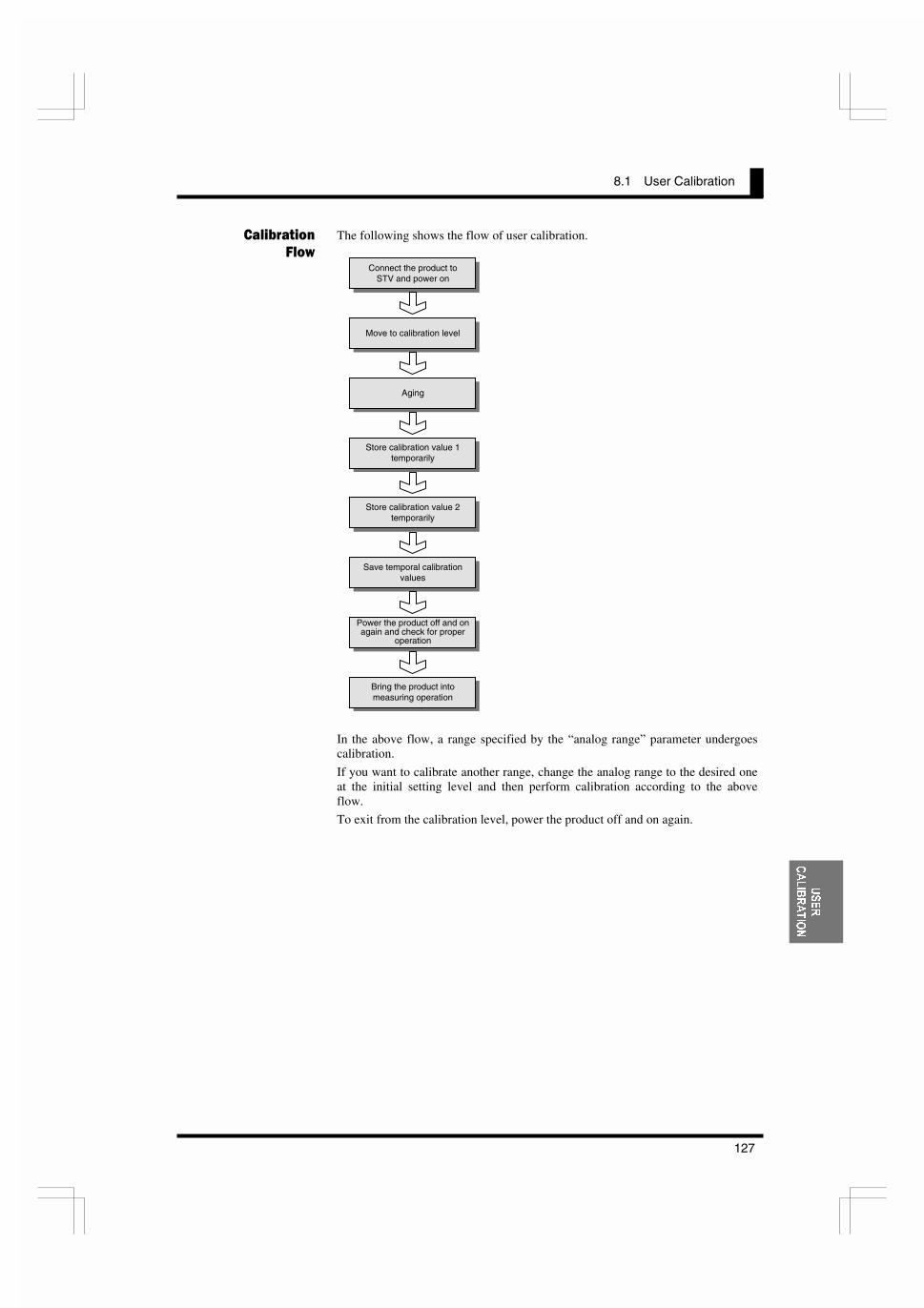
8.1 User Calibration
127
86(5
&$/,%5$7,21
The following shows the flow of user calibration.
In the above flow, a range specified by the “analog range” parameter undergoescalibration.
If you want to calibrate another range, change the analog range to the desired oneat the initial setting level and then perform calibration according to the aboveflow.
To exit from the calibration level, power the product off and on again.
���-����
#�'Connect the product to
STV and power on
Aging
Move to calibration level
Store calibration value 1temporarily
Store calibration value 2temporarily
Save temporal calibrationvalues
Power the product off and onagain and check for proper
operation
Bring the product intomeasuring operation
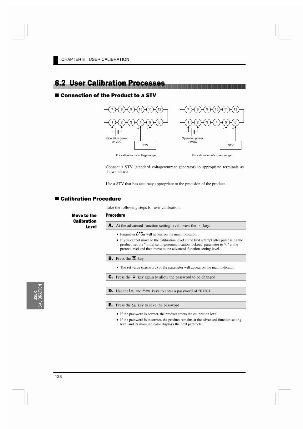
CHAPTER 8 USER CALIBRATION
128
86(5
&$/,%5$7,21
1����+ �����������������
������� �� �!� ������ �� � ��+
Connect a STV (standard voltage/current generator) to appropriate terminals asshown above.
Use a STV that has accuracy appropriate to the precision of the product.
��������� �������Take the following steps for user calibration.
���� ���
�$ At the advanced-function setting level, press the / key.
x Parameter :DFM will appear on the main indicator.
x If you cannot move to the calibration level at the first attempt after purchasing theproduct, set the "initial setting/communication lockout" parameter to "0" at theprotect level and then move to the advanced-function setting level.
.$ Press the 2 key.
x The set value (password) of the parameter will appear on the main indicator.
�$ Press the 2 key again to allow the password to be changed.
&$ Use the 2 and 4 keys to enter a password of “01201”.
�$ Press the / key to save the password.
x If the password is correct, the product enters the calibration level.
x If the password is incorrect, the product remains at the advanced-function settinglevel and its main indicator displays the next parameter.
���������
���-����
!����
7 8 9 10 11 12
1 2 3 4 5 6
Operation power24VDC
STV
+ -
7 8 9 10 11 12
1 2 3 4 5 6
Operation power24VDC
STV
+-
For calibration of voltage range For calibration of current range

8.2 User Calibration Processes
129
86(5
&$/,%5$7,21
���� ���
�$ Follow the above steps to move to thecalibration level.
x An aging timer count will appear on the mainindicator.
x The aging timer is a 30-minute timer and countsdown to 0.
x If a user calibration record is found, a calibrationrecord mark will appear.
.$ Perform aging until the aging timer countsdown to 0.(If the STV needs an aging time longer than 30minutes, continue aging until the agingrequirement of the STV is satisfied).
x If you press the / key in the middle of timercounting, aging is skipped and the parameter ofcalibration value 1 is displayed on the mainindicator.
�$ Press the / key to display the parameter ofcalibration value 1.
x The parameter corresponding to the currentanalog range will appear on the main indicator.For the relationship between the analog rangeand the parameter, refer to the table on the nextpage.
&$ Press the 2 key to display the set value of theparameter.
x The calibration value 1 will appear inhexadecimal on the main indicator.
�$ Use the STV to provide a reference signalcorresponding to calibration value 1.
x For the value of reference signals, refer to thetable on the next page.
������
���-����
!���� �����L
T
�����L
T
� ��=
T
�=
T
�����=
T
����L
T
2 2
/ / /Use 2 and 4 to enter thespecified password.
Correct password enteredIncorrectpassword entered
Next parameter atadvanced-functionsetting level Calibration level
L appears, indicating the product isat the calibration level.
�� ���L
T
Calibration record mark
#�� �L
T�
"T" is illuminated.
��"��L
T�
"SV" is illuminated.
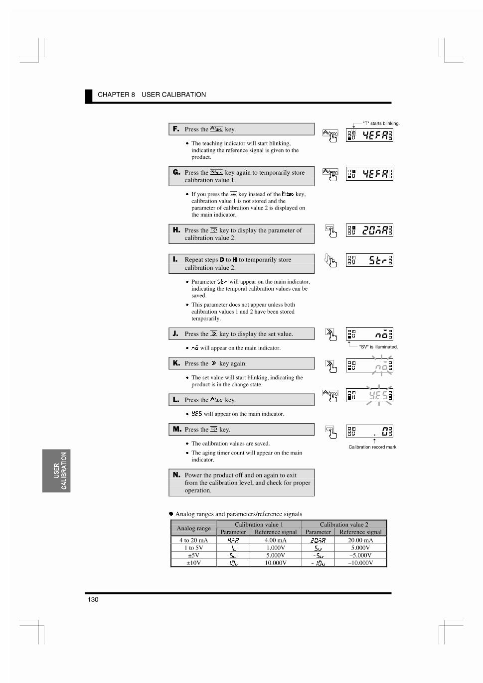
CHAPTER 8 USER CALIBRATION
130
86(5
&$/,%5$7,21
�$ Press the 4 key.
x The teaching indicator will start blinking,indicating the reference signal is given to theproduct.
�$ Press the 4 key again to temporarily storecalibration value 1.
x If you press the / key instead of the 4 key,calibration value 1 is not stored and theparameter of calibration value 2 is displayed onthe main indicator.
'$ Press the / key to display the parameter ofcalibration value 2.
�$ Repeat steps ' to + to temporarily storecalibration value 2.
x Parameter JKI will appear on the main indicator,indicating the temporal calibration values can besaved.
x This parameter does not appear unless bothcalibration values 1 and 2 have been storedtemporarily.
6$ Press the 2 key to display the set value.
x EF will appear on the main indicator.
>$ Press the 2 key again.
x The set value will start blinking, indicating theproduct is in the change state.
1$ Press the 4 key.
x P<J will appear on the main indicator.
($ Press the / key.
x The calibration values are saved.
x The aging timer count will appear on the mainindicator.
�$ Power the product off and on again to exitfrom the calibration level, and check for properoperation.
z Analog ranges and parameters/reference signals
Calibration value 1 Calibration value 2Analog range
Parameter Reference signal Parameter Reference signal4 to 20 mA �D8 4.00 mA ��D8 20.00 mA
1 to 5V �M 1.000V �M 5.000V±5V �M 5.000V ��M –5.000V
±10V ��M 10.000V ���M –10.000V
��"��L
T�
#�� �L
T�
����#L
T
�����L
T�
��+"�L
T�
��"��L
T�
"T" starts blinking.
"� ���L
T�
Calibration record mark
�����L
T�
"SV" is illuminated.

8.2 User Calibration Processes
131
7528%/(�
6+227,1**8,'(
���� ����������� �
����
9.1 Error Indications CCCCCCCCCCCCCCCCCCCCCCCCCCCCCCCCCCCCCCCCCCC132
9.2 Troubleshooting TableCCCCCCCCCCCCCCCCCCCCCCCCCCCCCCCCCCCCCC133
This chapter shows the meanings of error indications and theremedial actions to be taken in the event of error. It also containsa troubleshooting table that will be helpful in case a trouble mayarise.
�'�����

TROUBLESHOOTING GUIDE
132
7528%/(�
6+227,1**8,'(
2����7��������������
Levelindicator
Mainindicator
Error description Remedy
(Off) <���
RAM error Turn the K3GN off and on again.x If the error persists, RAM needs to be
replaced.x If the product is restored to normal
operation, the error was possibly caused bynoise interference. Check for noise sourcenear the product.
J <���
EEPROM error Turn the K3GN off and on again.x If the error persists, EEPROM needs to be
replaced.x If the product is restored to normal
operation, the error was possibly caused bynoise interference. Check for noise sourcenear the product.
The product received an analog valuethat fell outside the measuring range ofthe selected analog range.
Supply analog values that fall within themeasuring range.
The measuring range of each analog range is asfollows.
Analog range Measuring range4 to 20 mA 0 to 22 mA1 to 5V 0 to 5.5V±5V –5.5 to 5.5V±10V –11 to 11V
(Off)
J�<IIblinking
atintervalsof 0.5 s
You will see this indication when turningon the product at the first time afterpurchasing. This is because the inputsignal value is 0 mA at that time eventhough the range is factory set to 4 to 20mA.
At the initial setting level, select an input typeand an analog range according to yourapplication.
Enter an appropriate scaling input value.
(Off)
�����blinking
atintervalsof 0.5 s
The scaling display value exceeds 99999.
The scaling factor may be inappropriate.Review the scaling factor at the initial settinglevel.
Enter an appropriate scaling input value.
(Off)
�����blinking
atintervalsof 0.5 s
The scaling display value is lower than–19999.
The scaling factor may be inappropriate.Review the scaling factor at the initial settinglevel.

9.2 Troubleshooting Table
133
7528%/(�
6+227,1**8,'(
2���������� ����������
Symptom Probable cause RemedyReference
page
The “input type” parameter isset to “pulse”.
The forced-zero function is notavailable.
50
90
The forced-zero function isinoperative even though the4 key is pressed.
Forced-zero lockout is active. At the protect level, set theforced-zero function to“enable”.
48
The product does not enter theprotect level even though the .+ / is held down for 5 seconds.
The “move-to-protect-level”parameter is set to a value morethan 5.
Set the “move-to-protect-level”parameter to an appropriatevalue.
76
The “input-pulse frequencyrange” parameter is set to “30Hz”.
If the input pulse frequencyexceeds 30 Hz, set the “input-pulse frequency range”parameter to “5 kHz”.
52
88
Readouts vary greatly ordecrease with increasingrotational speed.
The input pulse frequencyexceeds 5 kHz.
Lower the input pulse frequencyto 5 kHz or less.
Note that the product does notgenerate an out-of-range error ifthe input pulse frequencyexceeds 5 kHz.
Readouts vary or are incorrecteven when the rotational speed islow.
The pulse width of ON/OFFsignals is too small.
Supply the product with pulsesthat have a width specified inthis manual.The product cannot recognizeinput pulses correctly unlesstheir width is as specified, evenif the rotational speed is low.
88
The main indicator reads 0 whenthe rotational speed is low.
The “auto-zero time” parameteris set to a value that is not morethan the maximum time intervalof input pulses.
Set the “auto-zero time”parameter to a value exceedingthe maximum time interval ofinput pulses.Otherwise, the auto-zerofunction may be triggeredimproperly.
68
86

TROUBLESHOOTING GUIDE
134
7528%/(�
6+227,1**8,'(
Symptom Probable cause RemedyReference
page
The set value of the “startupcompensation timer” parameteris too large.
Set the “startup compensationtimer” parameter to anappropriate value.When the input type is set to"pulse", the startupcompensation time can be set toup to 99.9 seconds.
70
86
The product continues to read“00000” on the main indicatorsince powered on.
The “process value hold”function is active.
Cancel “process value hold”.If the event input terminal isused for “process value hold”,powering on the product in theON state of the terminal willresult in a readout of “00000”,which is retained unless theterminal turns off.
89
The event/pulse input terminalscannot be turned on or off at allor sometimes.
The making residual currentand/or breaking leakage currentof input equipment are outsidethe specified limits.
Use such input equipment thatconforms to the requirements ofthe making residual current andbreaking leakage currentspecifications.Otherwise, the product cannotdetect the ON/OFF signals frominput equipment.
13
Wiring is incorrect. Check wiring for correctconnection and A/B polarity.
14The product does not returnresponses at all to the host PC.
The command frame contains awrong unit No.
Specify a correct unit No.Otherwise, the product will notreturn a response to the host PC.
97
Comparative output does notturn off even when a processvalue goes back to normal.
The set value of the “hysteresis”parameter is too large.
Set the “hysteresis” parameterto an appropriate value.
66
92

APPENDIX
135
$33(1',;
%< �����&�3
SpecificationsCCCCCCCCCCCCCCCCCCCCCCCCCCCCCCCCCCCCCCCCCCCCCC136
Parameter List CCCCCCCCCCCCCCCCCCCCCCCCCCCCCCCCCCCCCCCCCCCCC139
ASCII Code Table CCCCCCCCCCCCCCCCCCCCCCCCCCCCCCCCCCCCCCCCC140

APPENDIX
136
$33(1',;
�#�����������
������
Supply voltage 24 VDCOperating voltage range 85% to 110% of the rated supply voltagePower consumption(see note)
2.5W max. (at max. DC load with all indicators lit)
Insulation resistance 20 M: min. (at 500 VDC) between external terminal and case.Insulation provided between inputs, outputs, and power supply.
Dielectric withstandvoltage
1,000 VAC for 1 min between external terminal and case.Insulation provided between inputs, outputs, and power supply.
Noise immunity ±480 V on power supply terminals in normal mode, ±1,500 V in common mode, ±1 Ps,or 100 ns for square-wave noise with 1 ns
Vibration resistance Malfunction: 10 to 55 Hz, 10 min each in X, Y, and Z directions; acceleration: 9.8 m/s2
Destruction: 10 to 55 Hz, 30 min each in X, Y, and Z directions; acceleration: 19.6 m/s2
Shock resistance Malfunction: Models with transistor outputs: 196 m/s2 for 3 times each in X, Y, and ZdirectionsModels with relay contact outputs: 98 m/s2 for 3 times each in X, Y, andZ directions
Destruction: 294 m/s2 for 3 times each in X, Y, and Z directionsAmbient temperature Operating: –10°C to 55°C (with no condensation or icing)
Storage: –25°C to 65°C (with no condensation or icing)Ambient humidity Operating: 25% to 85% (with no condensation)Ambient atmosphere Must be free of corrosive gasEMC Emission Enclosure: EN55011 Group 1 class A
Emission AC Mains: EN55011 Group 1 class AImmunity ESD: EN61000-4-2: 4-kV contact discharge (level 2)
8-kV air discharge (level 3)Immunity-RF-interference: ENV50140: 10 V/m (amplitude modulated, 80
MHz to 1 GHz) (level 3)10 V/m (pulse modulated, 900 MHz)
Immunity Conducted Disturbance: ENV50141: 10 V (0.15 to 80 MHz) (level 3)Immunity Burst: EN61000-4-4: 2-kV power line (level 3)
2-kV I/O signal-line (level 4)Approved standards UL508 (pending), CSA22.2 (pending); conforms to EN50081-2, EN50082-2, EN61010-
1 (IEC1010-1); conforms to VDE106/part 100 (Finger Protection) when the terminalcover is mounted.
Weight Approx. 100 g
Note: A operation power supply capacity greater than the rated capacity is required when the Digital Panel Meter isturned ON. Do not forget to take this into consideration when using several Digital Panel Meters. When poweris supplied, all indicators will light and outputs will be OFF. When using startup compensation time operation,the display will read “00000” and all outputs will be OFF.

APPENDIX
137
$33(1',;
�#��-���#�� ����������� ������ ���#��(Incorporating G6K Relays)
Item Resistive load (cosø = 1)Rated load 1 A at 30 VDCRated carry current 1 A max. (at COM terminal)Max. contact voltage 60 VDCMax. contact current 1 A (at COM terminal)Max. switching capacity 30 VAMin. permissible load(P level, reference value)
10 mV, 10 PA
Mechanical life 50,000,000 times min. (at a switching frequency of 36,000 times/hr)Electrical life(at an ambient temperature of 23°C)
100,000 times min. (at the rated load with a switching frequency of 1,800times/hr)
������� ���#��
Rated load voltage 24 VDCMax. load current 50 mALeakage current 100 PA max.
��))��������
Item RS-485Transmission method 2-wire, half-duplexSynchronization method Start-stop synchronizationBaud rate 1,200/2,400/4,800/9,600/19,200 bpsTransmission code ASCIICommunications Reading/Writing
to the K3GNRead/write set values, read/write scaling values, enable/disable the writingof data through communications, forced-zero control, and other data.
(������ �����
Process Voltage/Current Inputs
Input Measuring range Measuring accuracy Input impedance Display range1.000 to 5.000 V/0.000 to 5.000 V
±0.1% FS ±1 digitmax. (at 23±3°C)
–5.000 to 5.000 V
DC voltage
–10.00 to 10.00 V±0.1% FS ±1 digitmax. (at 23±5°C)
1 M: min.
DC current 4.00 to 20.00 mA/0.00 to 20.00 mA
±0.1% FS ±1 digitmax. (at 23±3°C)
60 :
–19999 to 99999(with scalingfunction)
��* ������ ������-�#� �������� �#���
Input Measuring rangeMeasuring accuracy
(at 23±5°C)Displayable range
No-voltage contact (30 Hz max.) withON/Off pulse width of 16 ms min.
0.05 to 30.00 Hz
Open collector (5 kHz max.) withON/OFF pulse width of 90 Ps min.
0.1 to 5000.0 Hz
±0.1% FS ±1 digit max. –19999 to 99999(with scaling function)
&������ &��� &��#��� 9.� ��*4=5 ��))�������:
Displayable range –19999 to 99999

APPENDIX
138
$33(1',;
�!�����������
Input signal Process voltage�� WR�9�� WR�9���9����9�
Process current(4 to 20 mA, 0 to 20 mA)
No-voltage contact(30 Hz max. with ON/OFFpulse width of 16 ms min.)
Open collector(5 kHz max. with ON/OFFpulse width of 90 Ps min.)
Digital data display (by RS-485 communication)
A/D conversionmethod
Double integral method —
Sampling period 250 ms —Display refreshperiod
Sampling period (sampling times multiplied by number of averaging times if averageprocessing is selected.)
Pulse measurementmethod
— Periodic measurement —
ConnectableSensors
— ON residual voltage: 2.5 V max.OFF leakage current: 0.1 mA max.Load current: Must have a switching capacity of 15 mA min.
Must be able to reliably switch load currents of5 mA max.
Max. diaplayeddigits
5 digits (–19999 to 99999)
Display 7-segment digital display, character height: 7.0 mmPolarity display “–” is displayed automatically with a negative input signal.Zero display Leading zeros are not displayed.Scaling function Programmable with front-panel key inputs (range of display: –19999 to 99999). The decimal
point position can be set as desired.External controls(see note 1)
HOLD: (Measurement valueheld)
ZERO: (Forced-zero)
— HOLD: (Measurement valueheld)
ZERO: (Forced-zero)Hysteresis setting Programmable with front-panel key inputs (0001 to 9999)
Programmable Color DisplaySelectable output operating actionTeaching set valuesAverage processing (simple average)Lockout configurationCommunications writing control (communications output models only)
Other functions
Forced-zero set with frontpanel keysControl inputs (HOLD/ZERO) selection via frontpanel keysField calibration
Startup compensation time(0.00 to 99.9 s)Auto-zero time (0.0 to 19.9 s)
Forced-zero set with frontpanel keysControl inputs (HOLD/ZERO) selection via frontpanel keys
Relays: 2 SPST-NOTransistors: 3 NPN open collector
3 PNP open collector
—Output
Combinations:Communications output (RS-485) + relay outputs (2 SPST-NO);Communications output (RS-485) + transistor outputs (3 NPN open collector);Communications output (RS-485) + transistor outputs (3 PNP open collector)
Communications Communications function: RS-485Delay incomparativeoutputs (transistoroutputs)
750 ms max.
Enclosure ratings Front panel: NEMA4X for indoor use (equivalent to IP66)Rear case: IEC standard IP20Terminals: IEC standard IP20
Memory protection Non-volatile memory (EEPROM) (possible to rewrite 100,000 times)
Note 1: The minimum input time for control signals is 80 ms.
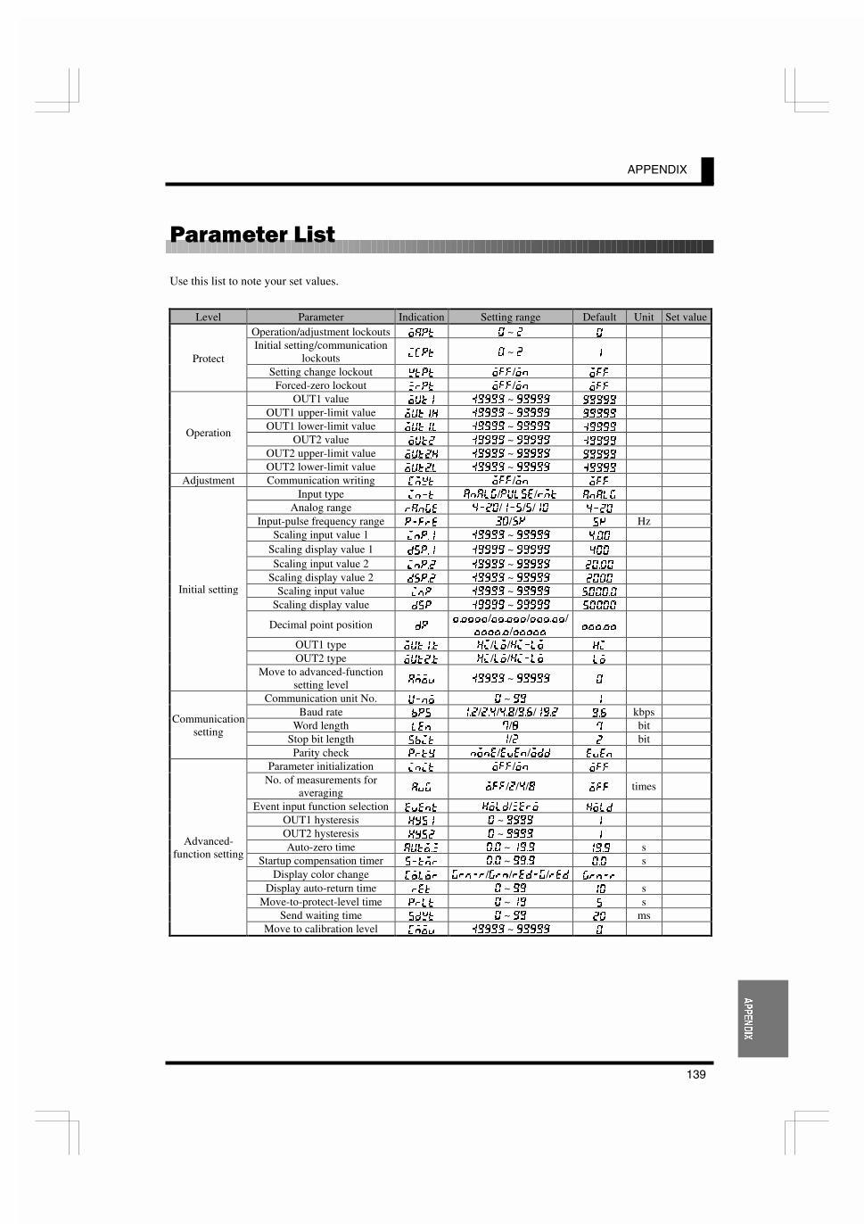
APPENDIX
139
$33(1',;
���)��� 1���
Use this list to note your set values.
Level Parameter Indication Setting range Default Unit Set valueOperation/adjustment lockouts F8GK � ~ � �
Initial setting/communicationlockouts @:GK � ~ � �
Setting change lockout NKGK F==/FE F==
Protect
Forced-zero lockout QIGK F==/FE F==
OUT1 value FLK� ����� ~ ����� �����
OUT1 upper-limit value FLK�? ����� ~ ����� �����
OUT1 lower-limit value FLK�C ����� ~ ����� �����
OUT2 value FLK� ����� ~ ����� �����
OUT2 upper-limit value FLK$? ����� ~ ����� �����
Operation
OUT2 lower-limit value FLK$C ����� ~ ����� �����
Adjustment Communication writing :DNK F==/FE F==
Input type @E�K 8E8C>/GLCJ</IDK 8E8C>
Analog range I8E>< ����/���/�/�� ����
Input-pulse frequency range G�=I< ��/�B �B HzScaling input value 1 @EG�� ����� ~ ����� ����
Scaling display value 1 ;JG�� ����� ~ ����� ���
Scaling input value 2 @EG�� ����� ~ ����� �����
Scaling display value 2 ;JG�� ����� ~ ����� ����
Scaling input value @EG ����� ~ ����� ������
Scaling display value ;JG ����� ~ ����� �����
Decimal point position ;G������/������/������/
������/����� ������
OUT1 type FLK��K ?@/CF/?@�CF ?@
OUT2 type FLK��K ?@/CF/?@�CF CF
Initial setting
Move to advanced-functionsetting level 8DFM ����� ~ ����� �
Communication unit No. L�EF � ~ �� �
Baud rate 9GJ ���/���/���/���/���� ��� kbpsWord length C<E �/� � bit
Stop bit length J9@K �/� � bit
Communicationsetting
Parity check GIKP EFE</<M<E/F;; <M<E
Parameter initialization @E@K F==/FE F==
No. of measurements foraveraging 8M> F==/�/�/� F== times
Event input function selection <M<EK ?FC;/Q<IF ?FC;
OUT1 hysteresis ?PJ� � ~ ���� �
OUT2 hysteresis ?PJ� � ~ ���� �
Auto-zero time 8LKF�Q ��� ~ ���� ���� sStartup compensation timer J�KDI ��� ~ ���� ��� s
Display color change :FCFI >IE�I/>IE/I<;�>/I<; >IE�I
Display auto-return time I<K � ~ �� �� sMove-to-protect-level time GICK � ~ �� � s
Send waiting time J;NK � ~ �� �� ms
Advanced-function setting
Move to calibration level :DFM ����� ~ ����� �

APPENDIX
140
$33(1',;
����� ���� �����
UpperLower 0 1 2 3 4 5 6 7
0 NUL DLE SPACE 0 @ P p
1 SOH DC1 ! 1 A Q a q
2 STX DC2 “ 2 B R b r
3 ETX DC3 # 3 C S c s
4 EOT DC4 $ 4 D T d t
5 ENQ NAK % 5 E U e u
6 ACK SYN & 6 F V f v
7 BEL ETB ‘ 7 D W g w
8 BS CAN ( 8 H X h x
9 HT EM ) 9 I Y i y
A LF SUB * : J Z j z
B VT ESC + ; K [ k {
C FF FS , < L ¥ l |
D CR GS - = M ] m }
E SO RS . > N ^ n ~
F SI US / ? O _ o DEL

���;
A
adapter .................................................................. 10address................................................................ 100adjustment ............................................................ 38adjustment level.................................................... 40advanced-function setting..................................... 38advanced-function setting level............................ 40alphabets............................................................... 44analog input ...................................................... 5, 13analog photoelectric sensor .................................. 20analog range ................................................. 51, 114ASCII character.................................................... 97auto-zero............................................................... 86auto-zero function ................................................ 24auto-zero time............................................... 68, 115average processing ............................................... 87
B
baud rate ............................................................. 115BCC................................................................ 97, 98
C
calibration............................................................. 38change state .......................................................... 44chattering noise removal ...................................... 88check and change OUT set value ......................... 45clearing all parameters ......................................... 62command frame.................................................... 97command text ....................................................... 97commands and responses ................................... 105communication..................................................... 14communication parameters................................... 60communication procedure .................................... 96communication reading ...................................... 116communication setting ......................................... 38communication setting level................................. 40communication specification................................ 96communication unit No. ..................................... 115communication writing ...................................... 109communication writing (setting area 0).............. 117comparative output..................................... 2, 14, 91CompoWay/F ....................................................... 96contact output ......................................................... 5current leakage with transistor turned ON............ 13current value....................................................... 113
D
decimal point position .................................. 58, 115dimensions............................................................ 10
display auto-return time ............................... 74, 115display color......................................................... 72display color change .................................... 93, 115
E
echoback test................................................ 99, 112end code ............................................................... 98error indications ................................................. 132ETX................................................................ 97, 98event input................................................ 13, 64, 88event input function ........................................... 115event input/pulse input ........................................... 5
F
FINS..................................................................... 96forced-forced-zero execution ............................. 103forced-zero ............................................... 46, 88, 90forced-zero cancel.............................................. 103forced-zero execution/cancel ............................. 109forced-zero lockout ...................................... 48, 114frame .................................................................... 97
H
hexadecimal number ............................................ 97hysteresis.................................................. 20, 66, 92
I
I/O circuits ............................................................. 5I/O terminal connections...................................... 12initial setting................................................... 30, 38initial setting level................................................ 40initial setting/communication lockouts ........ 48, 114input circuit diagrams ............................................ 5input pulse frequency................................... 82, 114input range over ................................................... 30input type ..................................................... 50, 114input-pulse frequency range................................. 52inrush current ....................................................... 19installation............................................................ 10installation procedure........................................... 11internal block diagram ........................................... 6
K
key protect............................................................ 48

L
levels.....................................................................38load .......................................................................14load current ...........................................................13lower-limit action................................18, 22, 24, 91
M
main features...........................................................2measurement .........................................................82Model number legend .............................................4monitor state .........................................................44move to protect level ..................................103, 110move to setting area 1 .................................103, 110move-to-protect-level time ...........................76, 115MRC .....................................................................99MRES ...................................................................99
N
N88 BASIC.........................................................121node No...........................................................97, 98number of measurements for averaging..........63, 87numerics................................................................44
O
OFF leakage current .............................................13ON and OFF pulses...............................................88ON residual current...............................................13operating voltage range.........................................13operation ...............................................................38operation instruction .............................99, 103, 120operation/adjustment lockouts ......................48, 114OUT1 hysteresis .................................................115OUT1 lower-limit value........................................46OUT1 type ..........................................................115OUT1 upper-limit value........................................46OUT1 value ..........................................................46OUT2 hysteresis .................................................115OUT2 lower-limit value........................................46OUT2 type ..........................................................115OUT2 upper-limit value........................................46OUT2 value ..........................................................46output circuit diagrams ...........................................5output operating action .........................................59outside-the-range action........................................91
P
panel cutout dimensions........................................10parameter ..............................................................42parameter writing (setting area 1) .......................119parity bit..............................................................115password ...............................................................40PMCR command ................................................123
power consumption ..............................................13power supply ........................................................13power supply capacity ..........................................13pressure sensor .....................................................22process meter........................................................30process value hold ..........................................88, 89programming example........................................121protect...................................................................38protect level ..........................................................40protect level parameter writing...........................118protocol macro....................................................123pulse input ......................................................13, 88
R
read controller attribute ................................99, 111read controller status.....................................99, 111read from variable area.................................99, 101read parameter ....................................................107read process value ..............................................105read remote input value ......................................106read status ...........................................................105read version ........................................................112remote indicator....................................................34remote input value ..............................................114response frame......................................................98response text .........................................................98
S
sampling ...............................................................82scaling...............................................................2, 84scaling display value ..........................................114scaling display value 1 .......................................114scaling display value 2 .......................................114scaling factor ............................................53, 55, 84scaling input value..............................................114scaling input value 1...........................................114scaling input value 2...........................................114scaling operation error....................................32, 57send waiting time..........................................78, 115serial communication board ...............................123set value................................................................44setting areas ........................................................104setting change lockout ..................................48, 114shift...................................................................3, 90SID .......................................................................97software reset...................................... 103, 104, 110SRC ......................................................................99SRES ....................................................................99startup compensation............................................86startup compensation time............................70, 115startup compensation timer...................................24status...................................................................113stop bit length .....................................................115STV ....................................................................128STX ................................................................97, 98sub-address .....................................................97, 98supply voltage.......................................................13

T
tachometer ............................................................ 32teaching function ............................................ 54, 56terminal arrangement............................................ 12terminal connection .............................................. 12tightening torque .................................................. 11transistor output...................................................... 6transmission line connection ................................ 96twisted-pair cable ................................................. 14
U
ultrasonic displacement sensor ............................. 16upper-limit action ......................... 18, 20, 22, 24, 91user calibration ................................................... 126
V
variable............................................................... 100variable area....................................................... 100variable area map ............................................... 113variable type....................................................... 100version................................................................ 113
W
waterproof............................................................ 11watertight packing................................................ 11word length ........................................................ 115write OUT set value ........................................... 107write parameter (setting area 1) ......................... 108write protect level parameter.............................. 108write to variable area.................................... 99, 102