1/32 DIN Digital Panel Meter K3GN · 1/32 DIN Digital Panel Meter K3GN B--67 Specifications...
13
1/32 DIN Digital Panel Meter K3GN B--66 1/32 DIN Digital Panel Meter K3GN Compact, Intelligent Panel Meter Offers NEMA 4X Water Resistance, Optional Communications Interface D Multi-purpose industrial process meter is ideal for many applications: Process meter: 6 analog input ranges available: 4 to 20 mA, 0 to 20 mA; 1 to 5 VDC, 0 to 5 VDC; --5 to +5 VDC, --10to +10 VDC RPM processor/Tachometer: 5 kHz max. input pulse frequency range Digital data display for PC or PLC (RS-485 communications) D Scaling in a wide range of engineering units. D Programmable output operation action, decimal point position setting, teaching function for input range, leading zero suppression and average processing. uC D Advanced display features enhance operator comprehension 5-digit display can be programmed to display red or green characters. Display can be programmed to change color when an output turns on. High-contrast backlit LCD display provides good legibility in most lighting conditions. D High accuracy: ±0.1% full scale. D Selectable outputs: 2 relay outputs, 3 transistor outputs, RS-485 communications. D Compact 1/32 DIN size saves panel space and shallow mounting depth allows thinner control cabinets: measures 48 W x 24 H x 83 D mm (1.89 x 0.94 x 3.27 inches). D Easy to configure from front panel or using Thermo Tools Software. Ordering Information J Panel Meters Stock Note: Shaded models are normally stocked. Input type Supply lt Output Model voltage No communications RS-485 communications DC process signal or NPN l i t 24 VDC Dual relays (SPST-NO) K3GN-NDC 24VDC K3GN-NDC-FLK 24VDC pulse input Three NPN open collector K3GN-NDT1 24VDC K3GN-NDT1-FLK 24VDC DC process signal or PNP l i t Dual relays (SPST-NO) K3GN-PDC 24VDC K3GN-PDC-FLK 24VDC pulse input Three PNP open collector K3GN-PDT2 24VDC K3GN-PDT2-FLK 24VDC J Programming Software Stock Note: Shaded models are normally stocked. Description Model Sets all panel meter parameters, initiates teaching function. Use with RS-485 communications models. Thermo Tools (See Note) Note: Contact Omron for current version information.
Transcript of 1/32 DIN Digital Panel Meter K3GN · 1/32 DIN Digital Panel Meter K3GN B--67 Specifications...
1/32 DIN Digital Panel Meter K3GNB--66
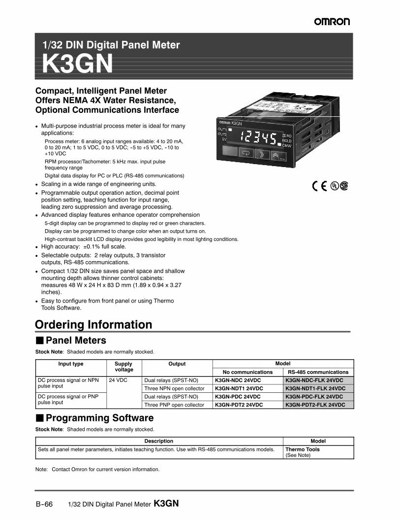
1/32 DIN Digital Panel Meter
K3GNCompact, Intelligent Panel MeterOffers NEMA 4X Water Resistance,Optional Communications Interface
D Multi-purpose industrial process meter is ideal for manyapplications:
Process meter: 6 analog input ranges available: 4 to 20 mA,0 to 20 mA; 1 to 5 VDC, 0 to 5 VDC; --5 to +5 VDC, --10 to+10 VDC
RPM processor/Tachometer: 5 kHz max. input pulsefrequency range
Digital data display for PC or PLC (RS-485 communications)
D Scaling in a wide range of engineering units.
D Programmable output operation action, decimal pointposition setting, teaching function for input range,leading zero suppression and average processing.
uC
D Advanced display features enhance operator comprehension
5-digit display can be programmed to display red or green characters.
Display can be programmed to change color when an output turns on.
High-contrast backlit LCD display provides good legibility in most lighting conditions.
D High accuracy: ±0.1% full scale.
D Selectable outputs: 2 relay outputs, 3 transistoroutputs, RS-485 communications.
D Compact 1/32 DIN size saves panel space and shallowmounting depth allows thinner control cabinets:measures 48 W x 24 H x 83 D mm (1.89 x 0.94 x 3.27inches).
D Easy to configure from front panel or using ThermoTools Software.
Ordering Information
JPanel MetersStock Note: Shaded models are normally stocked.
Input type Supplylt
Output Modelp yp pp yvoltage
p
No communications RS-485 communications
DC process signal or NPNl i t
24 VDC Dual relays (SPST-NO) K3GN-NDC 24VDC K3GN-NDC-FLK 24VDCp gpulse input
Three NPN open collector K3GN-NDT1 24VDC K3GN-NDT1-FLK 24VDC
DC process signal or PNPl i t
Dual relays (SPST-NO) K3GN-PDC 24VDC K3GN-PDC-FLK 24VDCp gpulse input
Three PNP open collector K3GN-PDT2 24VDC K3GN-PDT2-FLK 24VDC
JProgramming SoftwareStock Note: Shaded models are normally stocked.
Description Model
Sets all panel meter parameters, initiates teaching function. Use with RS-485 communications models. Thermo Tools(See Note)
Note: Contact Omron for current version information.
1/32 DIN Digital Panel Meter K3GN B--67
Specifications
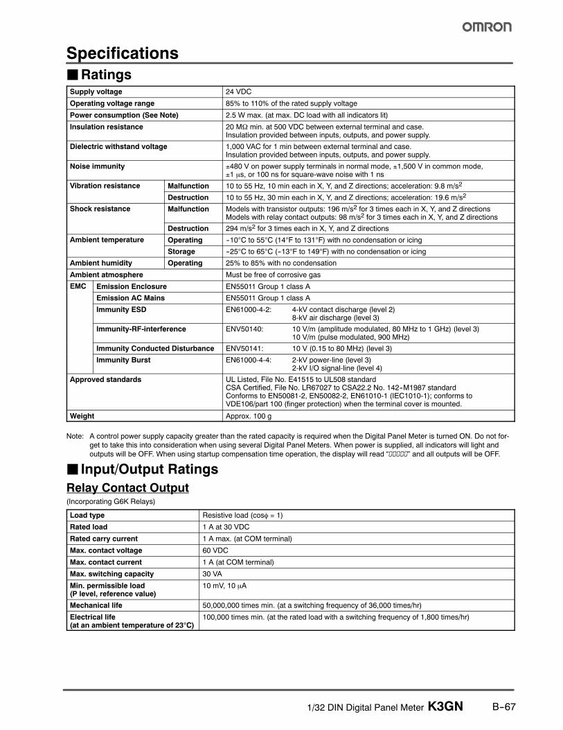
JRatingsSupply voltage 24 VDC
Operating voltage range 85% to 110% of the rated supply voltage
Power consumption (See Note) 2.5 W max. (at max. DC load with all indicators lit)
Insulation resistance 20 MΩ min. at 500 VDC between external terminal and case.Insulation provided between inputs, outputs, and power supply.
Dielectric withstand voltage 1,000 VAC for 1 min between external terminal and case.Insulation provided between inputs, outputs, and power supply.
Noise immunity ±480 V on power supply terminals in normal mode, ±1,500 V in common mode,±1 µs, or 100 ns for square-wave noise with 1 ns
Vibration resistance Malfunction 10 to 55 Hz, 10 min each in X, Y, and Z directions; acceleration: 9.8 m/s2
Destruction 10 to 55 Hz, 30 min each in X, Y, and Z directions; acceleration: 19.6 m/s2
Shock resistance Malfunction Models with transistor outputs: 196 m/s2 for 3 times each in X, Y, and Z directionsModels with relay contact outputs: 98 m/s2 for 3 times each in X, Y, and Z directions
Destruction 294 m/s2 for 3 times each in X, Y, and Z directions
Ambient temperature Operating --10°C to 55°C (14°F to 131°F) with no condensation or icingp
Storage --25°C to 65°C (--13°F to 149°F) with no condensation or icing
Ambient humidity Operating 25% to 85% with no condensation
Ambient atmosphere Must be free of corrosive gas
EMC Emission Enclosure EN55011 Group 1 class A
Emission AC Mains EN55011 Group 1 class A
Immunity ESD EN61000-4-2: 4-kV contact discharge (level 2)8-kV air discharge (level 3)
Immunity-RF-interference ENV50140: 10 V/m (amplitude modulated, 80 MHz to 1 GHz) (level 3)10 V/m (pulse modulated, 900 MHz)
Immunity Conducted Disturbance ENV50141: 10 V (0.15 to 80 MHz) (level 3)
Immunity Burst EN61000-4-4: 2-kV power-line (level 3)2-kV I/O signal-line (level 4)
Approved standards UL Listed, File No. E41515 to UL508 standardCSA Certified, File No. LR67027 to CSA22.2 No. 142--M1987 standardConforms to EN50081-2, EN50082-2, EN61010-1 (IEC1010-1); conforms toVDE106/part 100 (finger protection) when the terminal cover is mounted.
Weight Approx. 100 g
Note: A control power supply capacity greater than the rated capacity is required when the Digital Panel Meter is turned ON. Do not for-
get to take this into consideration when using several Digital Panel Meters. When power is supplied, all indicators will light and
outputs will be OFF. When using startup compensation time operation, the display will read “00000” and all outputs will be OFF.
J Input/Output Ratings
Relay Contact Output(Incorporating G6K Relays)
Load type Resistive load (cosφ = 1)
Rated load 1 A at 30 VDC
Rated carry current 1 A max. (at COM terminal)
Max. contact voltage 60 VDC
Max. contact current 1 A (at COM terminal)
Max. switching capacity 30 VA
Min. permissible load(P level, reference value)
10 mV, 10 µA
Mechanical life 50,000,000 times min. (at a switching frequency of 36,000 times/hr)
Electrical life(at an ambient temperature of 23°C)
100,000 times min. (at the rated load with a switching frequency of 1,800 times/hr)
1/32 DIN Digital Panel Meter K3GNB--68
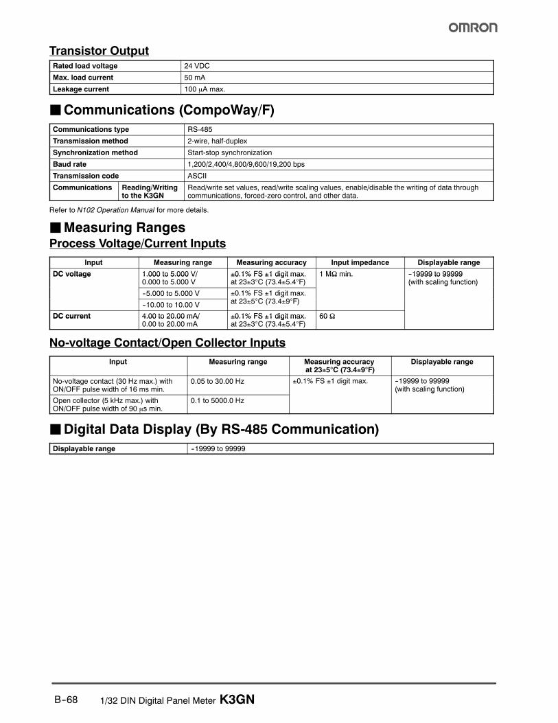
Transistor OutputRated load voltage 24 VDC
Max. load current 50 mA
Leakage current 100 µA max.
JCommunications (CompoWay/F)
Communications type RS-485
Transmission method 2-wire, half-duplex
Synchronization method Start-stop synchronization
Baud rate 1,200/2,400/4,800/9,600/19,200 bps
Transmission code ASCII
Communications Reading/Writingto the K3GN
Read/write set values, read/write scaling values, enable/disable the writing of data throughcommunications, forced-zero control, and other data.
Refer to N102 Operation Manual for more details.
JMeasuring RangesProcess Voltage/Current Inputs
Input Measuring range Measuring accuracy Input impedance Displayable range
DC voltage 1.000 to 5.000 V/ ±0.1% FS ±1 digit max. 1 MΩ min. --19999 to 99999DC voltage 1.000 to 5.000 V/0.000 to 5.000 V
±0.1% FS ±1 digit max.at 23±3°C (73.4±5.4°F)
1 MΩ min. 19999 to 99999(with scaling function)
--5.000 to 5.000 V ±0.1% FS ±1 digit max.t 23 5°C (73 4 9°F)
( t sca g u ct o )
--10.00 to 10.00 V
gat 23±5°C (73.4±9°F)
DC current 4.00 to 20.00 mA/ ±0.1% FS ±1 digit max. 60 ΩDC current 4.00 to 20.00 mA/0.00 to 20.00 mA
±0.1% FS ±1 digit max.at 23±3°C (73.4±5.4°F)
60 Ω
No-voltage Contact/Open Collector Inputs
Input Measuring range Measuring accuracyat 23±5°C (73.4±9°F)
Displayable range
No-voltage contact (30 Hz max.) withON/OFF pulse width of 16 ms min.
0.05 to 30.00 Hz ±0.1% FS ±1 digit max. --19999 to 99999(with scaling function)
Open collector (5 kHz max.) withON/OFF pulse width of 90 µs min.
0.1 to 5000.0 Hz
( t sca g u ct o )
JDigital Data Display (By RS-485 Communication)
Displayable range --19999 to 99999
1/32 DIN Digital Panel Meter K3GN B--69
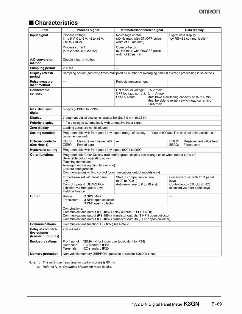
JCharacteristicsItem Process signal Ratemeter/tachometer signal Data display
Input signal Process voltage(1 to 5 V, 0 to 5 V, --5 to +5 V,--10 to +10 V)
Process current(4 to 20 mA, 0 to 20 mA)
No-voltage contact(30 Hz max. with ON/OFF pulsewidth of 16 ms min.)
Open collector(5 kHz max. with ON/OFF pulsewidth of 90 µs min.)
Digital data display(by RS-485 communication)
A/D conversionmethod
Double integral method ---
Sampling period 250 ms ---
Display refreshperiod
Sampling period (sampling times multiplied by number of averaging times if average processing is selected.)
Pulse measure-ment method
--- Periodic measurement ---
Connectablesensors
--- ON residual voltage: 2.5 V max.OFF leakage current: 0.1 mA max.Load current: Must have a switching capacity of 15 mA min.
Must be able to reliably switch load currents of5 mA max.
Max. displayeddigits
5 digits (--19999 to 99999)
Display 7-segment digital display, character height: 7.0 mm (0.28 in)
Polarity display “--” is displayed automatically with a negative input signal
Zero display Leading zeros are not displayed
Scaling function Programmable with front-panel key inputs (range of display: --19999 to 99999). The decimal point position canbe set as desired.
External controls(See Note 1)
HOLD: Measurement value heldZERO: Forced zero
--- HOLD: Measurement value heldZERO: Forced zero
Hysteresis setting Programmable with front-panel key inputs (0001 to 9999)
Other functions Programmable Color Display (red and/or green; display can change color when output turns on)Selectable output operating actionTeaching set valuesAverage processing (simple average)Lockout configurationCommunications writing control (communications output models only)
Forced-zero set with front panelkeysControl inputs (HOLD/ZERO)selection via front panel keysField calibration
Startup compensation time(0.00 to 99.9 s)Auto-zero time (0.0 to 19.9 s)
Forced-zero set with front panelkeysControl inputs (HOLD/ZERO)selection via front panel keys
Output Relays: 2 SPST-NOTransistors: 3 NPN open collector
3 PNP open collector
---
Combinations:Communications output (RS-485) + relay outputs (2 SPST-NO);Communications output (RS-485) + transistor outputs (3 NPN open collector);Communications output (RS-485) + transistor outputs (3 PNP open collector)
Communications Communications function: RS-485 (See Note 2)
Delay in compara-tive outputs(transistor outputs)
750 ms max.
Enclosure ratings Front panel: NEMA 4X for indoor use (equivalent to IP66)Rear case: IEC standard IP20Terminals: IEC standard IP20
Memory protection Non-volatile memory (EEPROM; possible to rewrite 100,000 times)
Note: 1. The minimum input time for control signals is 80 ms.
2. Refer to N102 Operation Manual for more details.
1/32 DIN Digital Panel Meter K3GNB--70
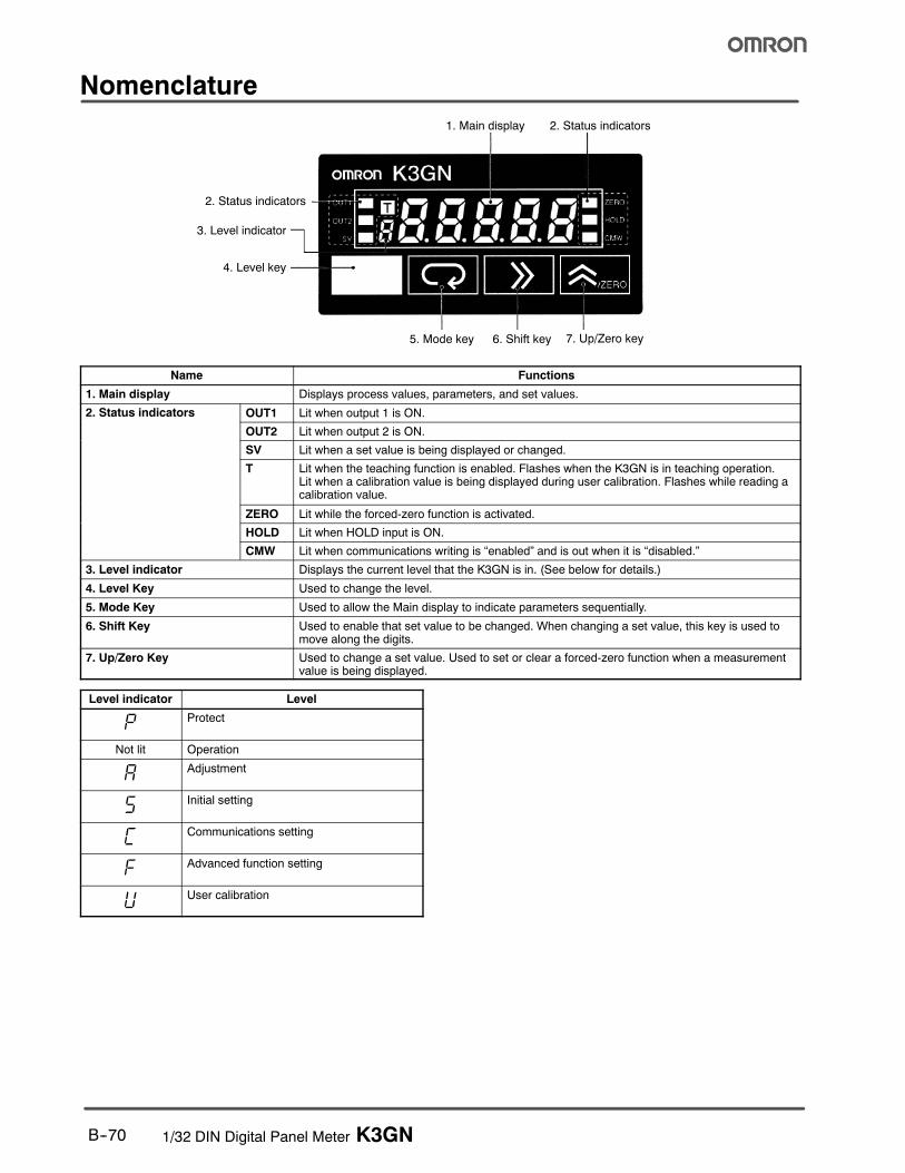
Nomenclature
1. Main display
2. Status indicators
3. Level indicator
4. Level key
2. Status indicators
7. Up/Zero key6. Shift key5. Mode key
Name Functions
1. Main display Displays process values, parameters, and set values.
2. Status indicators OUT1 Lit when output 1 is ON.
OUT2 Lit when output 2 is ON.
SV Lit when a set value is being displayed or changed.
T Lit when the teaching function is enabled. Flashes when the K3GN is in teaching operation.Lit when a calibration value is being displayed during user calibration. Flashes while reading acalibration value.
ZERO Lit while the forced-zero function is activated.
HOLD Lit when HOLD input is ON.
CMW Lit when communications writing is “enabled” and is out when it is “disabled.”
3. Level indicator Displays the current level that the K3GN is in. (See below for details.)
4. Level Key Used to change the level.
5. Mode Key Used to allow the Main display to indicate parameters sequentially.
6. Shift Key Used to enable that set value to be changed. When changing a set value, this key is used tomove along the digits.
7. Up/Zero Key Used to change a set value. Used to set or clear a forced-zero function when a measurementvalue is being displayed.
Level indicator Level
p Protect
Not lit Operation
a Adjustment
s Initial setting
c Communications setting
f Advanced function setting
u User calibration
1/32 DIN Digital Panel Meter K3GN B--71
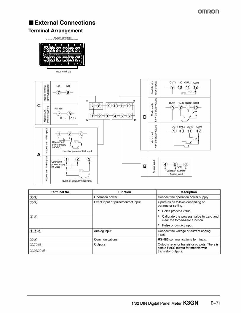
JExternal Connections
Terminal Arrangement
Output terminals
Input terminals
Modelswithout
communications
Modelswith
communications
NC NC
RS-485
B (+) A (--)
7 8
7 8
C
ModelswithNPNinputs
ModelswithPNPinputs
Operationpower supply24 VDC
1 2 3
1 2 3
Event or pulse/contact input
Event or pulse/contact input
AModelswith
Modelswith
relayoutputs
NPNtransistoroutputs
Analoginput
Modelswith
PNPtransistoroutputs
9 10 11 12
9 10 11 12
9 10 11 12
OUT1
PASS
NC
OUT2
COM
OUT1
OUT2
COM
OUT1 PASS OUT2 COM
D
Voltage Current
Analog input
4 5 6B
C D
A B
7 8 9 10 11 12
1 2 3 4 5 6
COM
Operationpower supply24 VDC
Terminal No. Function Description
A-B Operation power Connect the operation power supply.
C-B Event input or pulse/contact input Operates as follows depending onparameter setting:
• Holds process value.
C-A
p
• Calibrate the process value to zero andclear the forced-zero function.
• Pulse or contact input.
D,F-E Analog input Connect the voltage or current analoginput.
G-H Communications RS-485 communications terminals.
I,K-L Outputs Outputs relay or transistor outputs. There isalso a PASS output for models with
I,J,K-Lalso a PASS output for models withtransistor outputs.
1/32 DIN Digital Panel Meter K3GNB--72
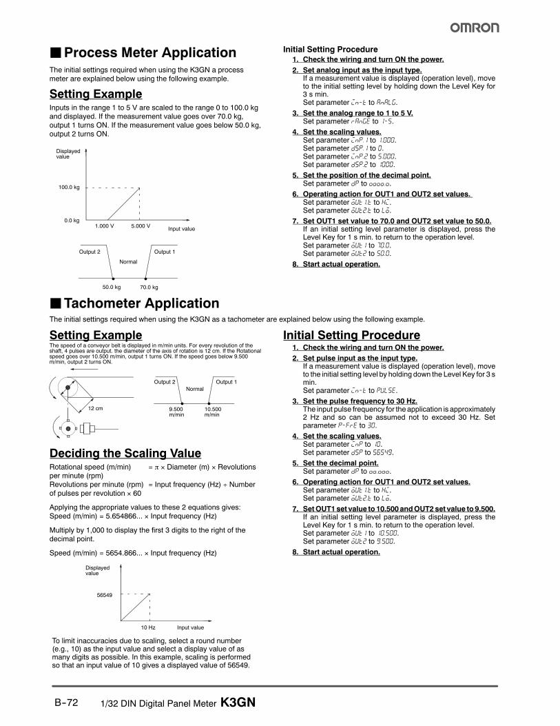
JProcess Meter ApplicationThe initial settings required when using the K3GN a process
meter are explained below using the following example.
Setting ExampleInputs in the range 1 to 5 V are scaled to the range 0 to 100.0 kgand displayed. If the measurement value goes over 70.0 kg,
output 1 turns ON. If the measurement value goes below 50.0 kg,output 2 turns ON.
100.0 kg
0.0 kg1.000 V 5.000 V
Input value
Output 2 Output 1
50.0 kg 70.0 kg
Normal
Displayedvalue
Initial Setting Procedure1. Check the wiring and turn ON the power.
2. Set analog input as the input type.If a measurement value is displayed (operation level), moveto the initial setting level by holding down the Level Key for3 s min.Set parameter in-t to analg.
3. Set the analog range to 1 to 5 V.Set parameter range to 1-5.
4. Set the scaling values.Set parameter inp.1 to 1.000.Set parameter dsp.1 to 0.Set parameter inp.2 to 5.000.Set parameter dsp.2 to 1000.
5. Set the position of the decimal point.Set parameter dp to %%%%.%.
6. Operating action for OUT1 and OUT2 set values.Set parameter out1.t to hi.Set parameter out2.t to lo.
7. Set OUT1 set value to 70.0 and OUT2 set value to 50.0.If an initial setting level parameter is displayed, press theLevel Key for 1 s min. to return to the operation level.Set parameter out1 to 70.0.Set parameter out2 to 50.0.
8. Start actual operation.
JTachometer ApplicationThe initial settings required when using the K3GN as a tachometer are explained below using the following example.
Setting ExampleThe speed of a conveyor belt is displayed in m/min units. For every revolution of theshaft, 4 pulses are output. the diameter of the axis of rotation is 12 cm. If the Rotationalspeed goes over 10.500 m/min, output 1 turns ON. If the speed goes below 9.500m/min, output 2 turns ON.
Output 2 Output 1
9.500m/min
10.500m/min
Normal
12 cm
Deciding the Scaling ValueRotational speed (m/min) = π × Diameter (m) × Revolutionsper minute (rpm)Revolutions per minute (rpm) = Input frequency (Hz) ÷ Numberof pulses per revolution × 60
Applying the appropriate values to these 2 equations gives:
Speed (m/min) = 5.654866... × Input frequency (Hz)
Multiply by 1,000 to display the first 3 digits to the right of thedecimal point.
Speed (m/min) = 5654.866... × Input frequency (Hz)
56549
10 Hz Input value
To limit inaccuracies due to scaling, select a round number(e.g., 10) as the input value and select a display value of asmany digits as possible. In this example, scaling is performedso that an input value of 10 gives a displayed value of 56549.
Displayedvalue
Initial Setting Procedure1. Check the wiring and turn ON the power.
2. Set pulse input as the input type.If a measurement value is displayed (operation level), moveto the initial setting level by holding down the Level Key for 3 smin.Set parameter in-t to pulse.
3. Set the pulse frequency to 30 Hz.The input pulse frequency for the application is approximately2 Hz and so can be assumed not to exceed 30 Hz. Setparameter p-fre to 30.
4. Set the scaling values.Set parameter inp to 10.Set parameter dsp to 56549.
5. Set the decimal point.Set parameter dp to %%.%%%.
6. Operating action for OUT1 and OUT2 set values.Set parameter out1.t to hi.Set parameter out2.t to lo.
7. SetOUT1set value to 10.500 andOUT2 set value to 9.500.If an initial setting level parameter is displayed, press theLevel Key for 1 s min. to return to the operation level.Set parameter out1 to 10.500.Set parameter out2 to 9.500.
8. Start actual operation.
1/32 DIN Digital Panel Meter K3GN B--73
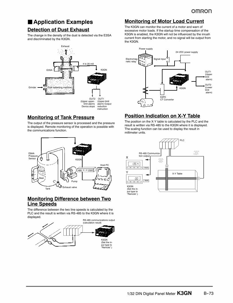
JApplication Examples
Detection of Dust ExhaustThe change in the density of the dust is detected via the E3SA
and discriminated by the K3GN.
Exhaust
Grinder Dust collecting machine
E3SA
4 to 20 mA
K3GN
OUT1OUT2(Upper upper-
limit alarm)Device stops
(Upper-limitalarm) Outputreductioninstruction
Monitoring of Tank PressureThe output of the pressure sensor is processed and the pressure
is displayed. Remote monitoring of the operation is possible withthe communications function.
E8AAPressureSensor
Foam
Beer
TankExhaust valve
Pump
K3GN
Host PC
485 232C
Monitoring Difference between TwoLine SpeedsThe difference between the two line speeds is calculated by thePLC and the result is written via RS-485 to the K3GN where it is
displayed.RS-485 communications output(calculation result)
K3GN(Set the in-put type to“Remote”.)
Monitoring of Motor Load CurrentThe K3GN can monitor the current of a motor and warn ofexcessive motor loads. If the startup time compensation of the
K3GN is enabled, the K3GN will not be influenced by the inrushcurrent from starting the motor, and no signal will be output from
the K3GN.
Power supply
Electromag-netic relay
Signal input
K3GN
K3FKCT Converter
24-VDC power supply
OUT1(Upper-limitalarm)
OUT2(Lower-limitalarm)
Position Indication on X-Y TableThe position on the X-Y table is calculated by the PLC and the
result is written via RS-485 to the K3GN where it is displayed.The scaling function can be used to display the result in
millimeter units.
X
Y
PLC
mm
mm
X-Y Table
RS-485 Communica-tion output
00
135.4
K3GN(Set the in-put type to“Remote”.)
1/32 DIN Digital Panel Meter K3GNB--74
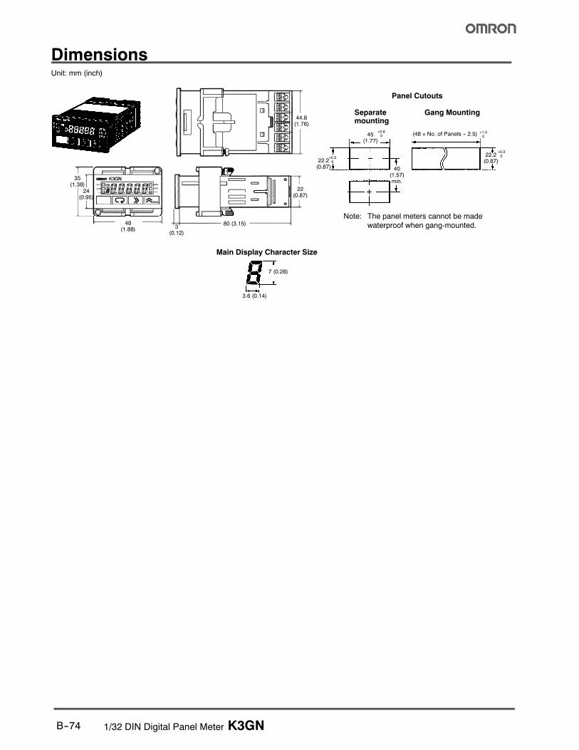
DimensionsUnit: mm (inch)
Main Display Character Size
Note: The panel meters cannot be made
waterproof when gang-mounted.
Panel Cutouts
Separatemounting
Gang Mounting
(48 × No. of Panels -- 2.5) +1.00
40(1.57)min.
22.2(0.87)
22.2(0.87)
45(1.77)
3.6 (0.14)
7 (0.28)
35(1.38)
24(0.95)
3(0.12)
80 (3.15)
22(0.87)
+0.3
0
+0.60
+0.3
0
44.8(1.76)
48(1.88)
1/32 DIN Digital Panel Meter K3GN B--75
PrecautionsWARNING
Donot touch the terminalswhile power is being supplied. Elec-trical shock may result. Also, do not touch the terminals with ascrewdriver while power is being supplied. Electrical shockmay result via the screwdriver.
Do not allow pieces ofmetal or wire clippings to enter the prod-uct. Electrical shock, fire, or malfunction may result.
Caution
Do not attempt to disassemble, repair, or alter the product.Electrical shock, fire, or malfunction may result.
Do not use the product where flammable or combustiblegasses are present.
The service life of the output relays depends on the switchingcapacity and switching conditions. Consider the actual ap-plication conditions and use the product within the rated loadand electrical service life.
Always maintain the load within ratings. Damage or burningmay result if the ratings are exceeded.
Always maintain the power supply voltage within specifica-tions. Damage or risk of fire may result if the specifications areexceeded.
Tighten the terminal screws securely. The recommendedtightening torque is 0.5 N S m. Loose screws may result inproduct failure or malfunction.
Performcorrect setting of the product according to the applica-tion. Failure to do somay cause unexpected operation, result-ing in damage to the unit or injury.
This product is not a safety device. Product failure may pre-vent operation of comparative outputs. Take safety measures,such as installing a separate monitoring system, to ensuresafety and to prevent serious accidents caused by such fail-ure, thus ensuring safety.
Observe the following precautions to ensure safety:
1. Do not connect anything to unused terminals.
2. Be sure to check each terminal for correct number and polar-ity before connection. Incorrect or reverse connection may
damage or burn out internal components of the K3GN.
3. Do not use the product in locations subject to the following:
S Dust or explosive gasses (e.g., sulfuric gas or ammoniagas).
S Condensation or icing as a result of high humidity.
S Outdoors or in direct sunlight.
S Splashing liquid or oil atmosphere.
S Direct radiant heat from heating equipment.
S Extreme changes in temperature.
4. Do not block heat dissipation around the product, i.e., providesufficient space for heat dissipation. Do not block the ventila-
tion holes on the back of the product.
5. Do not use paint thinner for cleaning. Use commercially avail-able alcohol.
6. Use a power supply meeting the power supply specifications
of the K3GN. Be sure that the rated voltage is achieved with-in 2 s after turning ON the power.
7. Use the K3GN within the specified temperature and humidity
ranges. When installing the K3GN in a panel, be sure that thetemperature around the K3GN (not the temperature aroundthe panel) does not exceed 55°C (131°F). If the K3GN is
subject to radiant heat, be sure that the temperature of thesurface of the K3GN exposed to the radiant heat does not
exceed 55°C (131°F) by providing a fan or other heatremoval method.
8. Store the K3GN within the specified temperature andhumidity ranges.
9. Do not lay heavy objects on the product during use orstorage. Doing so may deform or deteriorate the K3GN.
10. Conduct aging for 15 minutes min. after power is ON forcorrect measurement.
Mounting
Recommended panel thickness is 1 to 5 mm (0.04 to 0.20 inch).
Insert the K3GN in the square cutout, insert the adapter from theback, and push the K3GN into the cutout as far as possible. Use
screws to secure the K3GN. To make the K3GN waterproof,insert watertight packing in the K3GN.
Install the watertight packing in the proper direction. Note that the
packing is direction-sensitive.
When gang-mounting two or more products in a cutout, be surethat the ambient temperature does not exceed the specifications.
Mount the K3GN as horizontally as possible.
Separate the K3GN from machines generating high-frequencynoise, such as high-frequency welding machines and
high-frequency sewing machines.
Operation
A K3GN model with a relay contact or transistor output may notoutput any alarm signal normally if the model has an error. It is
recommended that an independent alarm device be connected tothe model.
The parameters are factory-set so that the K3GN will operate
normally. The settings of the parameters may be changedaccording to the application.
Wiring
Wire the power supply with the correct polarity. Wiring withincorrect polarity may result in damage or burning.
Wire the terminals using crimp terminals.
Tighten terminal screws to a torque of approx. 0.5 N S m.
Wire signal lines and power lines separately to reduce electricalnoise and interference.
Use M3 crimp terminals of the type shown below.
5.8 mm (0.23 in) max.
5.8 mm (0.23 in) max.
!
!
1/32 DIN Digital Panel Meter K3GNB--76
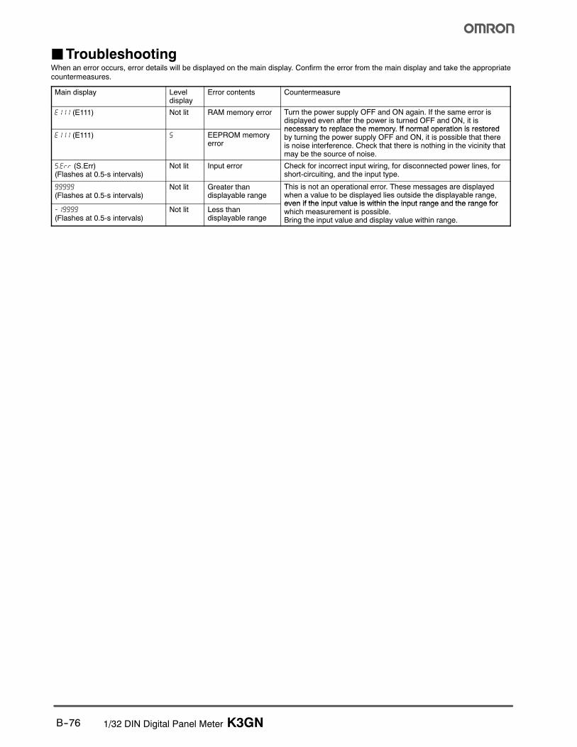
JTroubleshootingWhen an error occurs, error details will be displayed on the main display. Confirm the error from the main display and take the appropriatecountermeasures.
Main display Leveldisplay
Error contents Countermeasure
e111 (E111) Not lit RAM memory error Turn the power supply OFF and ON again. If the same error isdisplayed even after the power is turned OFF and ON, it isnecessary to replace the memory If normal operation is restored
e111 (E111) 5 EEPROM memoryerror
necessary to replace the memory. If normal operation is restoredby turning the power supply OFF and ON, it is possible that thereis noise interference. Check that there is nothing in the vicinity thatmay be the source of noise.
s.err (S.Err)(Flashes at 0.5-s intervals)
Not lit Input error Check for incorrect input wiring, for disconnected power lines, forshort-circuiting, and the input type.
99999
(Flashes at 0.5-s intervals)Not lit Greater than
displayable rangeThis is not an operational error. These messages are displayedwhen a value to be displayed lies outside the displayable range,even if the input value is within the input range and the range for
-19999
(Flashes at 0.5-s intervals)Not lit Less than
displayable range
even if the input value is within the input range and the range forwhich measurement is possible.Bring the input value and display value within range.
! ! "! # # ! $ %& ''(% %%) * + !! #
! %) % *
, - ( ! ! # * ! . !% # + *
/ 011 %2 $# # * % % ! %
## !%# # 3 " $
4 . . ! # . ! ! 3 % % !! ! # !! $ ! . ! ! # . % %*
5 67 * % ! # 3 # 7* 8 ! % $ $* !"% ! ! %* * # %
9 ( & %) * .
: 6 ;) % % # % ! 38 ! !!8 % ! % ! ! % ! ! 8 3 #
1 - # < . % = % % % % * #
# * $% 6* "
% ! 8 $ * !# $ %*
- # 8 $
. ( % *
$% # % ,1 "% % # $
> &.# > + .# $% 8 # % . % ! . % '&''&?;@&A>??AB??&?&&A7A!&C?&? 7;'7&-!*<AA"7A6?7A$&;&A!;&?(DA*7'"7B ? 67A& 6? ?7(<'? <?& 6 D& $-*<B&?(@A>'&-$&D7'A&D-&&?;7A&-DD&$- >7'' <7*'B ;&& D& ?&E<7?&;&A 6 D&7?7A&A-&-<& % . % % $ " * ? + %" % * % % # "$! + ! * 3 $# # % % ! ! . $ + $ ! ! %) "!% ! ? %* % # % % % % %% $% !! % % # # ! # ! % %#
, - '&&''&?D''A*&'7*'&6?&(7'!7A-7"?&( ? (A&E<&A7' -;$&! ' 6 ?67 ? ?"-<(7A?(;;&?(7''7AAB>B(AA&(&->7DD&$-!>D&D&?<(D('7;7*&-7A(A?(!>??AB!A&$'7$&A(&??7('7*7'7B 6 ! # % . # $%
/ 7 * ! % ! ! ! . + . !# "! * + $> !* . % . % $ *
2 ( % $ .# * A" * ! .# % * $ " ! * % #
4; ># A % . % * # % % * + % * $!"#% # % # %7# # #!## # * # # !
%< % % "! % $ * + $* + 3 ! # % $% % $ % ! ! ! . % # % .# % $! % % $= ! ##
! % & !% ! !#
! 3 ! !# ! 3 !%) #
! 3 8 8% # % % $
A&F&?<&D&?-<(6?A'7(7A7AF'F7A$&?7<?7@'76&??&?B>7D<&A<?7A$DD&B&;>D'&D*&&A-&7$A&---?&D&?7@!A-DD& &''&?+ ?-<( 7 ?&?'B ?&- A- 7A''&- 6?D&7A&A-&-<&>7D7AD&F&?''&E<7;&A?B&;
% % % + "% $! 3
, - # # % 7 + ! " 3 %) +>''%
/ ( % % # 7" % % ! D # ! " $% > %! % % . %8 + # $
2 & % 8 % # % # ! % ! !
$%"=GG<"=GGG ("=GG
Cat. No. H301-E3-1 6/04 Specifications subject to change without notice Printed in USA
! "#992; # !;*2F9
$%&'&&$&(
( -# %!7'415,
$)$*)+,,6< 3 =
,,((&&)&&
- ./ 012
111# # 3H/- 2.2"/4#
!56 ## !%11,:,5# !%11,25