Conical coaxial capacitors and their advantages...'::; Conical Coaxial Capacitors and Their...
3
Journa l of Research of the National Burea u of Standards-C. Engineering and Instrumentati on Vol. 63C, No. 2, Octo b er-December 1959 ::; Coni cal Coaxial Capacitors and Their Advantages M. C. Sel by l (Jun e 16, 1959) Adju sta ble capaci tors havin g el.ect rod es in the fOJ"m of coax ial cones or fru st ums h av e bpen used on ra re occasions in the past, but their pot e nti al s uperior i ty to oth er ty pes of cap ac it ors fOJ" some import a nt a pplication s has be en overlooked. Th e ad van tage' of t his geometry over cylindri cal or disk forms is t h at t he practic al cap aci ta nce rang e is s evera l t imes l arger. An exa mpl e ci tes the capacitance ranges f or the sa me m echan ica l a nd per- ce ntage aCCLl J ·acy of a di sk, cylindri ca l a nd conical ty pe to be 10, 'lO, an d 168 to 1, respec- tive ly. An a pproximate equati on was deriv ed for t hi s conical capacitOl· a nd close agree mcnt is shown between co mput ed a nd m eas umd valu es of capacitance versus el ect rod e displ ace- ment . Mult iple cone a nd speciall y shappd electro des are suggeste d to o btain large valu es of ca]x1eitance with 911 a ppr eciable sa vin g of s pa ce an d fur ther incr eased range of cap acitanc e. I I 1. Introdu ction Adjustabl e capacitors of coaAial form arc fre- quent ly more sui ta ble for a given appli cation than the conventi onal rotary or compr ession typ es. l ;" Variation of capacit a n ce in the form er is obtained by lin ear di s placemen t of one elec trode , usu ally a cylind er or a disk, with r es pect to another simil ar station ary elec trod e. U nfortunately , cylindri cal- and disk-type el ectrod es h ave a r el at ively limi ted capaci ty ran ge. Conical el ectrodes are intuitively I attractive b ecause they represent an int e rm ediat e ;" case b et ween cylindri cal and disk el ectrod es. So far as the author is aware, no expression for the capa ci ty of a conical stru ctur e has been d erived . Such an expr ession is given below and will be of he lp in d eter- minin g the efl'ect of the dimension and angle of I' the con e on capaci ty valu es a nd parti cul arly on th e range of capa city .2 This rang e is affected primaril y by two t hings, the mechani cal pr eseta bility and end eff ects. Th e fir t d etcrmin es the minimum or ma>.i- ;" mum cap acity which can be preset to a desired accuracy; this limiting fa ctor seems to be the mor e importan t of the t wo and will be treated below. • The end eff ect limits the minimum capacity and will be negl ected here. U nfortunat ely, thi s eff ect is rath er difficult to comput e or to estimate. In negl ecting it we favor the cylindri cal case wher e this fr e ff ect is mor e pronoun ced than in the other two cases. It will be shown that the conical capacitor has a considern bly wider range even if th e end eff ect 1· is negl ected. Let us ass ume a cer tain given cylindncal ele ct ri- > cally shi eld ed s pa ce wit hin whi ch an adju stable ca pa cit or is to be plac ed. Th e shield is usually I- ground ed . In cylindri cal geometry t he ca pacitance is directly proportional to the length of t he meshed sections. 1£ we are to be certain that all pr eset ,.. ca pa cities ar e a cc urat e to, s ay , ± 0.2 percent we I 1 J. c. Balsbaugh and P . H. Moon, A bridge for pr eCision power-factor f measurement s on sman oil samples, Trans. AIEE 52, 528 ( June 1933). , M . C. Selby, Anal ys is of coaxi al conical ca[)acitor (publication pending) . 517199- 59- -1 87 mu st mak e surc that the position of the tra veling el ectrode is al ways reprodu ced at l east to 0.2 per- ce nt ; the cri tical position will, of co ur se, be a t the minimum capa city. Fo r a mi crometer havin g a maximum t ravel of 2 in. and a r eseta bilit y of ± 0.1 mil every where a long t hi s travel, the s mall est meshed section will hav e to be 50 mils. The ratio of maxi - mum to minimum ca pa ci ty will therefore be 40 to 1. On the other h and , for pra ctical purposes, a di sk- type capaci tor ceases to behav e lik e a normal capa ci- tor approximately at separations exceeding the valu e of the radius of the disks. At high er sepa ration s t hese di sk s pla ced in side a s hi eld hav e rel atively high s hun t cap acities to the sb.ield . L et us consider in all cases 1 in. as the diam eter of the avail able cylindrical s pa ce ; the shi eld may be 1% or 2 in. in diameter. Th e criti cal po sition of the mi crometer in the case of disks will be at the maximum capa ci ty, namely at a disk separation of 50 mils. Th e ran ge will there fore be fi xed apprw,imately by the rat io of on e-half in . to 50 mils or 10 to 1. With conical el ectrodes on e can realize a rallge man y times that of a cylindri cal or di sk capa citor. 2. Conical Capacitor C onsider a capa citor form ed by two right frustums as shown in fi g ur e 1. Th e cro ss sect ion s hows the essent ial dimensional eleme nt s of this capacitor . L et the sections of the coni cal electrod e surfa ces indi - cate d by the leng th l be ref erred to as the "mesh ed" surfaces. Let also: 20 = angl e of the co nes. D = acljustable di sta nce b etween the apexes of the cones. As D in creases the ca pa citance decreases, because the di stances betw een the conical s urfac es in crease an d the le ngth of meshed s urf aces is reduced. h= the hei ght of the insid e cone CA) from its apex to the b ase of its eff ective meshed surf ace.
Transcript of Conical coaxial capacitors and their advantages...'::; Conical Coaxial Capacitors and Their...

Journa l of Research of the National Bureau of Standards-C. Engineering and Instrumentation
Vol. 63C, No. 2, October- December 1959
'::; Conical Coaxial Capacitors and Their Advantages
M. C. Selby
l (Jun e 16, 1959)
~ Adjustable capacitors having el.ectrodes in t he fOJ"m of coaxial cones or fru st ums have
bpen used on ra re occasions in the past, but their potential superiority to other types of capacitors fOJ" some importa nt a pplications has been overlooked. The ad van tage' of t his geometry over cylindrical or disk forms is t hat t he practical capacitance range is several t imes larger. An example cites the capacitance ranges for t he same m echan ical and percentage aCCLl J·acy of a disk, cylindrical and conica l type to be 10, 'lO, an d 168 to 1, respectively. An a pproximate equation was derived for t his con ical capacitOl· and close agreemcnt is shown between computed a nd m easumd values of capacitan ce versus electrode displacement. Multiple cone a nd specially s happd electrodes a re s uggested to o btain large values of ca]x1eita nce with 911 appreciab le sa vin g of space an d fur t her increased range of capacitance .
I I I ~
~
1. Introduction
Adjustable capacitors of coaAial form arc frequently m ore sui table for a given application than the conventional rotary or compression types. l
;" Variation of capacitance in the former is obtained by linear displacemen t of one electrode, usu ally a
~ cylinder or a disk , with r espect to another similar stationary elec trode. Unfortunately, cylindricaland disk-type electrodes h ave a r elatively limi ted capacity range. Conical electrodes are intuitively
I attractive because they represent an intermediate ;" case between cylindrical and disk electrodes. So far
as the author is aware, no expression for the capaci ty of a conical structure has been derived. Su ch an expression is given below and will be of h elp in determining the efl'ect of the dimension and a ngle of
I' th e cone on capacity values and particularly on th e range of capacity.2 This range is affected primarily by two things, the mechanical presetability and end effects. The fir t detcrmines the minimum or ma>.i-
;" mum capacity which can be prese t to a d esired accuracy; this limiting factor seems to be the more important of the two and will be treated b elow.
• The end effect limi ts the minimum capacity and will be neglected h ere. Unfortunately, this effect is rather difficul t to compute or to estimate. In neglecting it we favor the cylindrical case where this
fr effect is more pronounced than in th e other two cases. It will b e shown that the conical capacitor has a considern bly wider range even if the end effect
1· is neglected . Let us assume a cer tain given cylindncal electri
> cally shielded space wi thin which an adjustable capacitor is to be placed. The shield is usually
I- grounded . In cylindrical geometry t he capacitance is directly proportional to the length of the m eshed sections. 1£ we are to b e certain that all preset
,.. capacities are accurate to, say, ± 0.2 percen t we
I 1 J . c. Balsbaugh and P . H . Moon, A bridge for preCision power-factor f m easurements on sman oil samples, Trans. AIEE 52, 528 (June 1933) .
, M . C. Selby, Analys is of coaxial conical ca[)acitor (publication pending) .
517199- 59- -1 87
must make surc that the position of the traveling electrode is always r eprodu ced at least to 0.2 percent ; the cri tical posi tion will, of course, be a t the minimum capacity. For a micrometer having a maximum travel of 2 in. and a r esetability of ± 0.1 mil everywhere along this travel, th e smallest meshed section will have to be 50 mils. The ratio of maximum to minimum capacity will therefore b e 40 to 1.
On the other hand, for practical purposes, a disktype capacitor ceases to behave like a normal capacitor approximately at separations exceeding the value of the radius of the disks. At higher separations t hese disks placed inside a shield have relatively high shun t capacit ies to the sb.ield. Let us consider in all cases 1 in. as t he diam eter of the available cylindrical space ; the shield may be 1% or 2 in. in diameter. The critical position of the micrometer in the case of disks will b e at the maximum capacity, namely at a disk separation of 50 mils. The range will therefore b e fixed apprw,imately by the ratio of one-half in. to 50 mils or 10 to 1. With conical electrodes one can realize a rallge many times that of a cylindrical or disk capacitor.
2. Conical Capacitor
Consider a capacitor formed b y two right frustums as shown in figure 1. The cross section shows the essen tial dimensional elements of this capacitor. Let t he sections of t he conical electrode surfaces indicated by the leng th l b e r eferr ed to as the " meshed" surfaces. Let also:
20 = angle of the co nes. D = acljustable distance between the apexes of
th e cones. As D increases the capacitance decreases, because the distances between t he conical surfaces increase and t he length of mesh ed surfaces is r educed .
h= the h eight of the inside con e CA) from its apex to th e base of its effective m eshed surface.

- D - --11------- ------1
/' /'
FIGURE 1. Cross-sectional dimensions of conical capacitor. Solid lines Indicate the cond ucting surfaces of frustums A and E, respec
tively. Heavy dashed lines indicate a surface of a frustum taken at random parallel to the two condu cting surfaces. The thin dashed lines indicate tbe geometric extention of the 3 surfaces to the apexes of the cones.
A rigorous analytical solution for the conical case seems, unfortunately, unobtainable at this time. The classical approach and existing limitations to the particular boundary value problem were investigated and the results (not shown here) were discomaging. In order to develop more confidence in an approximate solution, one of the field construction methods, the graphical, was employed to justify the basic introductory assumption that the charge distribution over the conical surfaces is essentially uniform. A physical visualization of two closelyspaced parallel conducting closed surfaces of any shape may be of fmther assistance in this respect. Assuming a certain potential of the inner conductor and zero potential on the outer, the charge distribution over the inner will be a normal function of the con tom when the spacing between these conductors is infinity. As this spacing is reduced to zero the smface charges will be redistributed and will approach uniformity. At certain finite, and particularly at relatively small spacings, uniform charge distribution may be assumed with fairly good accuracy. The potential gradient is therefore pm'pendicular to the two metal smfaces nearly everywhere in the space between them. Since the conical conducting smfaces are parallel and coaxial, it follows that the electric lines in the dielectric space (assumed to be au __ ) are everywhere normal to both smfaces. Moreover, since the electrodes are equipotential surfaces, it follows also that everywhere over these smfaces and over any other surface parallel to and located between these conducting surfaces
dV E'11 = E=-dn (1)
where E is the potential gradient or the electric field intensity, 11 is unit vector normal to the smfaces, '1nd V is the potential at any point.
88
When relative positions and distances between the -'cones increase and begin to approach the order of magnitude of the height of the frustums, the wellknown condition is beulg approached when (J is a maximum near the apex of the inside cone and a <: minimum near the inside apex of the enclosing cone.
Referring to figme 1 and taking the surface Sf of any other coaxial frustum of half angle () located .. between the two conical electrodes and applying Gauss' law to this smface, the total enclosed charge Q is given by
... , (2)
The dielectric constant of the interelectrode space ~, is E, and the integral is applied only to the conical surface because the surfaces of the bases of the frustum by assumption do not contribute any electric flux. .~
From the geometry of the figme and the well- I known interrelations of C= Q/V
V - Edr=--JTa Q i ra dr Tb E7rl 'b (21' cos () - l sin ()
Q 1 ( 21'b cos () - l sin () ~~-~ n . 2E7rl cos () (21'a cos () - t sin ()
(3) '1
Expressing 1'a and 1'b in terms of hand D we have
C 27rEl cos ()
In[ 1 + 2D cos2 () J' 2h- l cos ()
The values of 1', 1'a, and l 'b are defined in figure l.
(4)
When the internal electrode is a cone, it may be • considered a frustum having a negligible small top section and an altitude h= l cos (). Then
J 27rEh C In[1 + 2(D/h) cos20]
(5) ~
Using the absolute rationalized practical system of .. units, h is in meters, and E~8.854X 10⁻¹² farads per meter (in vacuum and approxiJuately in air) and
3 . Computed and Measured Values
Figme 2 compares experimental data with calculations based on eq (6). () = 10 0 34' , (D+h)=2.845/1, height of enclosing cone=2.845/1, and the maximum displacement was 2 in.
In order to compare the range of the conical ca- .. pacitor with others, one must do so within the same mechanical precision limits, e.g., one must find the minimum value of D consistent with a reproducibility
:> 103
~
(> 10 2
o COMPUTED VALUE
:. ::I.. X MEASURED VALUE ::I..
I <oJ
~ 10 1
r '" >-u '" a.
p '" u
100 ..
10 -I I I ~ ---l --'----'--~~~~~
>J 0 0.2 0.4 0.6 O.B 1.0 1.2 1.4 1.6 1.8 2.0 O,in .
.. FIG URE 2. Capacitance vahws of right-cone continuously adjustable capacitor versus displacement.
of, say, 0.2 percen t in capacitance, which is the preI cision considered above in the hypothetical cylindri;- cal example. The deriva tive of 0 with respect to D
or h will yield the n ocessary information.
r where
F (h)
dO = dh [l + F (h)] o 11,
(7)
The error in the capacitance i~ thus larger than !. that in h by an additional factor F (ll,) , a function of h.
It is readily seen tha t F (h) is a pure numeric and ~ that h may be used in any units . The table below i gives one computed value of F (h) and expected error "for the capa eitor of figure 2 for
!:J.h~ .!.X 10-4 11, - 3 .
T ABLE 1.
})" h" P (h) t;,G/G Gmax. Gmin. Gmax. --G min. ._--
0.0.10 2. 795 56 0.2% 116. 1 0. 69 168
It appears, therefore, that for the same resetability of 11, as for the cylindrical and disk cases of 0.1 mil, a reproducibility of capaci tance values to 0.2 percent ,
r and a maximum displacemen t of 2 in. , the range of
r
the conical capacitor of the above dimensions would be about 168 to 1, as against 40 to 1 for the cylindrical and 10 to 1 for the disk type. The conical type capaci tor recen tly found prac tical application at the National Bureau of Standards in an attenuatorthermoelectric (AT) typ e r-f vol tmeter for vol tages from an average of 5 to 1000 v at frequencies of 1 to 10 Mc. 3
Figure 2 shows sa tisfactory agreemen t between computed and measured capacitance valu es of an experimental conical capacitor . Validity of formula (6) was also established for {I = 200 and 45° wi th good agreement between computed and measured values .
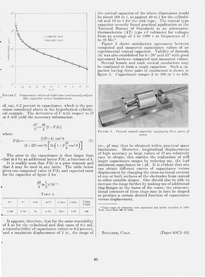
Several female and m ale conical conductors may be combined to form a s ingle capacitor. Such a capacitor having three pairs of conductors is shown in figure 3. Capacitance ranges 2 to 300 or 3 to 450,
89
F I GURE 3. Conical coaxial capacitor employing three pa'irs of cones.
etc. , pf may thus be ob tained within practical space limitations. :Moreover , longitudinal displacemen ts of high accuracy at large values of D are relatively easy to obtain ; this enables the realiza tion of still larger capacitance ranges by reducing say, the 3-pf minimum capacitance to 1 pf. It is eviden t that one can obtain differen t curves of capacitance versus di placement by changing the cross-sectional con tolll' of one or bo th surfaces of the electrodes from conical to other suitable shapes. One should also bc able to increase the range further by makin g use of addi tional ring-flanges at the bases of the cones; the cross-sectional contours of these rings may in turn be shaped to produce a certain desired function of capacitance versus displacemen t .
3 These types of voltmeters were announced and briefl y described in N BS T ech. News Bull. 40- 29 (1956) .
B OULDER, COLO. (Paper 63C2- 10)