Comparison of a pneumatic conveyor and a bucket elevator...
4
Comparison of a pneumatic conveyor and a bucket elevator on an energy and economic basis T.M. ROTHWELL1, C. VIGNEAULT2 and P.H. SOUTHWELL1 'Agricultural and Energy Engineering Ltd., Moorefield, ON, Canada NOG 2K0; and Agriculture Canada Research Station, bt-Jean-sur-Ricnelieu, PQ, Canada J3B 3E6. Contribution number: 335191.05.06R. Received 17 July 1990; accepted 14 May Rothwell, T.M., Vigneault, C. and Southwell, P.H. 1991. Comparison ofa pneumatic conveyor and a bucket elevator on an energy and economic basis. Can. Agric. Eng.33:395-397.In a series of testsmade ina feed mill to reduce energy consumption, a pneumatic conveyor and a bucket elevator were compared onboth anenergy and economic basis. The testsshowedthat a bucketelevatoris far moreefficientthan a pneumatic conveyor on an energy consumption basis and it should be considered in the design of new feed mills. Li existing mills, the economic analysis suggested that a bucket elevator be considered if there are problems with the pneumatic system already inplace orif the capacity of the mill needs to be increased. Un convoyeur pneumatique et un elevateur a godets ont ete compares au point de vue energetique et economique. Les tests ont demontres que 1'elevateur a godets etait beaucoup plus efficace que le convoyeur pneumatique. Ce systeme devrait etre fortement envisage dans la planification d'une nouvelle meunerie. Dans le cas d'une meunerie existante, le remplacement d'un systeme pneumatique parun elevateur ne devrait etre envisage que s'il est desuet ou de capacite insuffisante. INTRODUCTION According to the Canadian Feed Industry Association (CFIA 1978), most Canadian feed mills still employ bucket elevators or inclined screw conveyors to elevate ground products. The CFIA alsoestimates thatonly 15% of Canadian feed millsare equipped with pneumatic conveyors and these mills aremainly the newer ones. The main advantage of pneumatic conveyors over bucket elevators is their flexibility. The conveying pipes can be in stalled and movedin any direction, whereas bucket elevators require a straight and unobstructed vertical passageway. This advantage, however, is of little importance to feed mill man agers, because most grinding and conveying systems configurations are permanent. Two important aspects of com paring between any types of conveyors are the power requirements and the energy consumption. Power require ments can be obtained from either equipment specifications available from the suppliers or publications from associations involved in the feed industry. For example, the CFIA indicates that 39 kW are needed for pneumatic conveying of 21 t«h_1 of com from a hammermil], while only 10 kW are required for me chanical conveying under the same conditions (CFIA 1978). As far as conveying energy consumption is concerned, no actual measured data could be found in the literature. These data are important for a good comparison between pneumatic CANADIAN AGRICULTURAL ENGINEERING and mechanical conveying systems. The data availableon the motor nameplate are not a reliable indicator of the actual energy consumption while conveying. For example, pneu matic conveyor power requirements are determined on the basis of the volume ofair being moved through empty convey ing pipes. When solid material is introduced into the air stream, the energy consumption is reduced as indicated by a decline in the current needed for the motor. The levels of loading for the motor of the bucket elevating systems in steady-state operation could not be found either. It is conceivable, however, that motor sizing is,at least partially, based on start-up requirements or that someoverpowerallow ance is made for clearing blockages. The objective of this project was to compare a bucket elevator and a pneumatic conveyor on both an energy and economic basis, while conveying ground products away from a hammermill. MATERIALS AND METHOD The tests wereperformed at a commercialfeed mill in Elmira, ON, between November 1984 and December 1986. At this feedmill, the replacement of an existing pneumatic conveyor had been planned in order to increase the capacity of the grinding/conveying system. It was decided that the existing pneumatic conveyor wouldbe replaced by a bucket elevator. This presented a good opportunity to compare both conveyors and to measure power and energy requirements on operating conveyors. The pneumatic conveyor was monitored before replacement and the bucket elevator was monitored after its installation. The 37 kW pneumatic system was used to move ground product away from a 93 kW Schutte 1080 hammermill. The product was conveyed vertically to a turn head distributor located 18.3 m above the hammermill. The pneumatic system consisted mainly of a three-stage Kice model ZSP-16 turbine. This turbine was located between a centrifugal separator, into which the product was drawn, and a downstream bag house which filtered the air before ejection to the atmosphere. This system was monitored in three separate tests. The quantity of whole corn to be ground was weighed for each test. The time takenfor thegrindingand conveyingoperationswas measured using a stop watch. The power factor was determined using both a kVA anda kWmeter. In the second test,a clamp-on kW 395
Transcript of Comparison of a pneumatic conveyor and a bucket elevator...

Comparison of a pneumatic conveyor and abucket elevator on an energy and economic
basisT.M. ROTHWELL1, C. VIGNEAULT2 and P.H. SOUTHWELL1
'Agricultural and Energy Engineering Ltd., Moorefield, ON, Canada NOG 2K0; and Agriculture Canada Research Station,bt-Jean-sur-Ricnelieu, PQ, Canada J3B 3E6. Contribution number: 335191.05.06R. Received 17 July 1990; accepted 14 May
Rothwell, T.M., Vigneault, C. and Southwell, P.H. 1991. Comparisonofa pneumatic conveyor and a bucket elevator on anenergy andeconomicbasis.Can. Agric.Eng.33:395-397.In a seriesof testsmadeina feed mill to reduce energy consumption, a pneumatic conveyorand abucket elevator were compared onboth anenergy and economicbasis. The testsshowedthat a bucketelevatoris farmoreefficientthana pneumatic conveyor on an energy consumption basis andit shouldbe considered in the design ofnew feed mills. Li existing mills, theeconomic analysis suggested that a bucket elevator be considered ifthere are problems with the pneumatic system already inplace orifthecapacity of the mill needs to be increased.
Un convoyeur pneumatique et un elevateur a godets ont etecompares au point de vue energetique et economique. Les tests ontdemontres que 1'elevateur a godets etait beaucoup plus efficace que leconvoyeur pneumatique. Ce systeme devrait etre fortement envisagedans la planification d'une nouvelle meunerie. Dans le cas d'unemeunerie existante, leremplacement d'un systeme pneumatique parunelevateur ne devrait etre envisage que s'il est desuet ou de capaciteinsuffisante.
INTRODUCTION
According to the Canadian Feed Industry Association (CFIA1978), most Canadian feed mills stillemploy bucket elevatorsor inclined screw conveyors to elevate ground products. TheCFIA alsoestimates thatonly 15% of Canadian feed millsareequipped with pneumatic conveyors and these mills aremainlythe newer ones.
The main advantage of pneumatic conveyors over bucketelevators is their flexibility. The conveying pipes can be installed and moved in any direction, whereas bucket elevatorsrequire a straight and unobstructed vertical passageway. Thisadvantage, however, is of little importance to feed mill managers, because most grinding and conveying systemsconfigurations arepermanent. Two important aspects ofcomparing between any types of conveyors are the powerrequirements and the energy consumption. Power requirements can be obtained from either equipment specificationsavailablefrom the suppliers or publications from associationsinvolved in the feed industry. Forexample, the CFIA indicatesthat 39 kW are needed for pneumatic conveying of21 t«h_1 ofcom from a hammermil], while only 10 kWare required for mechanical conveying under the same conditions (CFIA 1978).
As far as conveying energy consumption is concerned, noactual measured data could be found in the literature. Thesedata are important for a good comparison between pneumatic
CANADIAN AGRICULTURAL ENGINEERING
and mechanical conveying systems.The data availableon themotor nameplate are not a reliable indicator of the actualenergy consumption while conveying. For example, pneumatic conveyor power requirements are determined on thebasis ofthe volume ofairbeing moved through empty conveying pipes. When solid material is introduced into the airstream, the energy consumption is reduced as indicated by adecline in the current needed for the motor.
The levels of loading for the motor of thebucket elevatingsystems in steady-state operation could not be found either. Itisconceivable, however, that motor sizing is,at least partially,based onstart-up requirements or that someoverpowerallowance is made for clearing blockages.
The objective of this project was to compare a bucketelevator and a pneumatic conveyor on both an energy andeconomic basis, while conveying groundproducts away froma hammermill.
MATERIALS AND METHOD
The tests wereperformed at a commercialfeed mill in Elmira,ON, between November 1984 and December 1986. At thisfeedmill, the replacement of an existing pneumatic conveyorhad been planned in order to increase the capacity of thegrinding/conveying system. It was decided that the existingpneumatic conveyor wouldbe replaced by a bucketelevator.This presented a good opportunity tocompare both conveyorsand to measure power and energy requirements on operatingconveyors. The pneumatic conveyor was monitored beforereplacement and the bucket elevator was monitored after itsinstallation.
The 37 kW pneumatic system was used to move groundproduct away from a 93 kW Schutte 1080 hammermill. Theproduct was conveyed vertically to a turn head distributorlocated 18.3 mabove thehammermill. Thepneumatic systemconsisted mainly of a three-stage Kice model ZSP-16 turbine.This turbine was located between a centrifugal separator, intowhich the product was drawn, and a downstream bag housewhich filtered the air before ejection to the atmosphere. Thissystem was monitored in three separate tests. The quantity ofwholecorn to be ground was weighed for each test. The timetakenfor thegrindingand conveyingoperationswasmeasuredusing a stop watch. The power factor was determined usingboth akVA anda kWmeter. In thesecond test,a clamp-on kW
395

meterwasusedtomeasureelectricalpowerinputtotheturbinemotorwhileconveyingproduct.Thispermittedcomputationofthepowerandtheenergyconsumptionbasedoncurrentreadingstakenwithaclamp-onammeter.Dividingthepowerrequiredbythemeasuredrateyieldedthespecificconveyingenergyvalueforeachtest.
Uponcompletionofthepneumaticconveyingtests,thebucketelevatingsystem,specifiedinTableI,wasinstalled.Afterperformingoneconveyingtest,theaspirationfanwasadjusted.Thissystemwasmonitoredinsixseparatetests.Twotestswereperformedusingapproximatelythesameconveyingrateasforthepneumaticsystemandfourtestswereperformedusingtheconveyingratecorrespondingtothemaximumgrindingcapacityofthehammermilloperatedunderdifferentconditions.Theprocedurefortestingthebucketelevatorwassimilartotheoneusedforthepneumaticsystem.Asgrindingproceeded,elevatormotorcurrentvalueswerecontinuouslyrecordedandtheaspirationfancurrentwasmeasuredataregularinterval.
Forpracticalpurposes,thefollowingparameterswereusedtorepresenttheeconomicanalysis:
Productionofmanufacturedfeed
QuantityofmaterialgroundHammermillaveragegrindingrateHoursofhammermilloperation
50000t-y"135000t-y"'
8.5fh"
4120h-y"1l
Thesenumbersrepresentamediumcapacitymill,asCanadianfeedmillcapacitiesrangefromlessthan10000t«y"tomorethan100000t-y"1(Rothwelletal.1986).
TableI.Specificationsofthebucketelevatortested
Bucketsize203mmx127mm
Spacing254mm
Headpulleydiameter610mm
Headpulleyspeed60rpm
Beltvelocity1.9m-s*1Feedlocationondown-side
Drivemotor3.7kW
Aspirationfanmotor3.7kW
Nominalmaximumcapacity29t-h"1Elevationdistance18.3m
RESULTSANDDISCUSSION
Energysignificance
Twoadvantagesareassociatedwiththebucketelevator,namely,lowerenergyconsumptionaswellaslowermaximumpowerdemand,whichconsistentlyreducecapitalneeds.AsshowninTableII,thepneumaticconveyorrequiredapowerof27.5kWandanenergyof4.77kWh«t_1whereasthebucketelevatorrequiredpowerof4.7kWandanenergyof0.88kWh't"1whenthesesystemshadapproximatelythesameconveyingrateofgroundproduct.Theconveyingenergydroppedfurther,toalowof0.41kWh'twhenconveyingabout12.7Mi"1ortotalpowerof5.2kW.Furthermore,itshouldbenotedthattheconveyingenergyvaluesforthebucketelevatoralsoincludedtheenergyusedtodrivethe
396
aspirationfan.Thisindicatesthatthebucketelevatorconveyinggroundproducttotheheightof18.3mwasmuchmoreefficient.Forboththebucketelevatorandthepneumaticconveyor,highermaterialflowratesresultedinreducedspecificconveyingenergyrequirements.
Althoughcornwasusedasthegrindingmaterialintheconveyingtrials,themaximumconveyingandgrindingrates,forcomwerenotattainedinallinstances.Therefore,inthecaseofafeedmillhavingahammermillaveragegrindingrateof8.5Mi"1some4.1kWh't"1ofenergycouldbesaved,byreplacingapneumaticconveyorwithabucketelevator,andacorresponding22.3kWreductioninpeakpowerdemandwouldalsoresult.Basedontheannualconveyingof350001,thehypotheticalmillwouldsave143500kWh.
Economicsignificance
Thecomparativecapitalcostsfora37kWpneumaticconveyingsystemanda3.7kWbucketelevatingsystem,includingaspirationfan,areestimatedtobe$20000and$30000respectively,includingmotors,starters,electricalandmillwrightinglabor.Assuming4120hofoperationannually,10%interestandastraightline15yearsdepreciation,withnosalvagevalue,thehourlyfixedcostsofoperationarethen$0.81and$1.21forthepneumaticandbucketconveyors,respectively.Ataconveyingrateof8.5t«h",thecorrespondingfixedcostsare$0,095and$0,142pertonneofmaterialelevated,andhence,thebucketelevatingsystementailsa$1645annualfixedcostpremiumoveritspneumatically-drivencounterpart.However,itmustberecognizedthat,inthisparticularinstance,themaximumcapacityofthebucketelevatoris29Ml,thusmorethanthreetimesthatofthepneumaticconveyor.Consequently,thebucketelevatorsystemallowsforincreasedproductionratesarisingfromexpandedgrindingcapacity,atlittleadditionalcost.
Intermsofmaintenancerequirementsthesystemswereroughlyequivalent,accordingtomaintenancepersonnelatthefeedmillwheretheresearchwasconducted.Partialwearingofeitherconveyortypecausesacorrespondingpartialreductionincapacity.Forexample,wornpipesandwornbuckets,whichmayleak,bothresultinlowerworkrates.Itcanbearguedthatbucketelevatorworkratesaremoreeasilyadjustedbysimplychangingbeltspeedbutthereisalimitedbeltspeedrange,outsideofwhichproperdischargeofmaterialcannotbeaccomplished.
Thefinancialcostsforconveyingenergyare:
Pneumaticsystem:4.77kWh't"1x35000t^y"1x$0.05kWh"1=$8350y'1
Bucketelevator:
0.88kWh-t"1x35000fy"1x$0.05kWh"1=$1540y'1Saving-$6810y'1
Virtuallyallfeedmills,inadditiontopayingforelectricalenergyconsumption,alsopayamonthly(peak)demandcharge,thecostofwhichdependsonthesupplier,butwhichusuallyrangesbetween$3.72and$4.60kWforanyexcessover50kW.Consequently,assumingademandcostof$4.00kW"1,itcanbeseenthatthebucketelevatingsystem,inloweringelectricalpowerdemandby22.3kW,providesafurthermonthlysavingof$89.20.Thecombinedannualen-
ROTHWELL,VIGNEAULTandSOUTHWELL
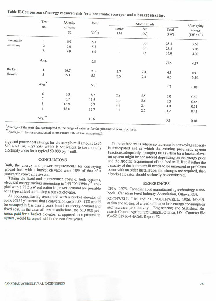
Table n.Comparison of energy requirements for apneumatic conveyor and a bucket elevator.
Pneumatic
conveyor
Bucket
elevator
Test Quanityof corn
(t)
Rate
(th"1)
Motor Loads Conveyingenergy
(kWhf1)
no.motor
(A)
fan
(A)
Total
(kW)
1
2
3
6.9
5.6
7.9
5.1
5.7
6.5
-
30
30
27
28.3
28.2
26.0
5.55
5.05
4.00
Avg.
4
5
Avg.*
6
7
8
9
Avg.**
16.7
15.1
7.3
8.7
16.9
18.8
5.8
5.3
5.3
5.3
8.5
11.5
9.7
12.7
10.6
2.7
2.5
2.8
3.0
2.8
3.0
2.4
2.3
2.5
2.6
2.4
2.5
27.5
4.8
4.5
4.7
5.0
5.3
4.9
5.2
5.1
4.77
0.91
0.85
0.88
0.59
0.46
0.51
0.41
0.48
'Average of the tests that correspond to the range of rates as for the pneumatic conveyor tests.Average ofthe tests conducted atmaximum rate ofthe hammermill.
ergy and power cost savings for the sample mill amount to $6810 +$1 070 =$7 880, which is equivalent to the monthlyelectricity costs for a typical 50 000 t-y"1 mill.
CONCLUSIONS
Both, the energy and power requirements for conveyingground feed with a bucket elevator were 18% of that of apneumatic conveying system.
Taking the fixed and maintenance costs of both systems,electrical energy savings amounting to 143 500 kWh.y"1, coupled with a 22.3 kW reduction in power demand are possiblefor a typical feed mill using a bucket elevator.
An economjc saving associated with a bucket elevator ofsome $6235y" means that aconversion costof$30 000 wouldbe recouped in less than 5 years based on energy demand andfixed cost. In the case of new installations, the $10 000 premium paid for a bucket elevator, as opposed to a pneumaticsystem, would berepaid within the two first years.
CANADIAN AGRICULTURAL ENGINEERING
In those feed mills where no increase in conveying capacityis anticipated and in which the existing pneumatic systemfunctions adequately, changing this system fora bucket elevator system might beconsidered depending onthe energy priceand thespecific requirement of the feedmill. But if eitherthecapacity ofthe hammermill needs tobe increased orproblemsoccur with an older installation and changes are required, thena bucket elevator should seriously beconsidered.
REFERENCES
CFIA. 1978. Canadian feed manufacturing technology Handbook. Canadian Feed Industry Association, Ottawa, ON.ROTHWELL, T.M. and P.H. SOUTHWELL. 1986. Modification and testing ofa feed mill to reduce energy consumptionand increase productivity. Engineering and Statistical Research Centre, Agriculture Canada, Ottawa, ON. Contract file#34SZ.01916-4-EC68. Report#2
397
d ,n„, .,, ERRATUMPage 30, Volume 33, No. 1, January 1991 was missing. It is printed below.Distance (cm)
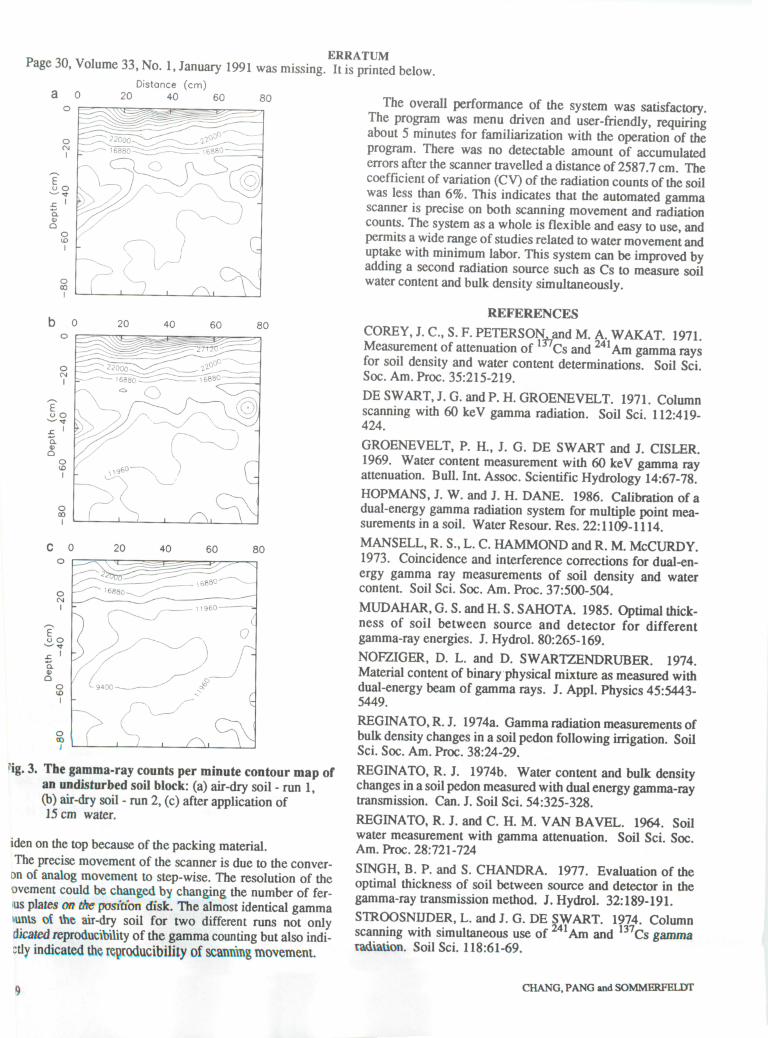
?ig. 3. The gamma-ray counts perminute contour map ofan undisturbedsoil block: (a) air-dry soil - run 1,(b) air-dry soil - run 2, (c)after application of15 cm water.
iden on the top because of thepacking material.Theprecise movement of the scanner is due to the conver-
on of analog movement to step-wise. The resolution of theovement could be changedby changing the numberof ferns plates on the position disk. The almost identical gamma>uMs of 1he air-dry soil for two different runs not onlyHeated reproducibility of the gamma counting butalso indi-;tly indicated the reproducibility ofscanning movement.
l)
The overall performance of the system was satisfactory.The program was menu driven and user-friendly, requiringabout 5 minutes for familiarization with the operation of theprogram. There was no detectable amount of accumulatederrors after thescanner travelled a distanceof 2587.7 cm. Thecoefficient of variation (CV)of theradiation counts of the soilwas less than 6%. This indicates that the automated gammascanner is precise on both scanning movement and radiationcounts. The system asa whole is flexible andeasy to use, andpermits a widerange of studies relatedto watermovement anduptake with minimum labor. This system can be improved byadding a second radiation source such as Cs to measure soilwatercontent and bulkdensity simultaneously.
REFERENCES
COREY, J. C, S.F. PETERSON andM. A.WAKAT. 1971.Measurement of attenuation of 137Cs and 241Am gamma raysfor soil density and water content determinations. Soil Sci.Soc. Am. Proc. 35:215-219.
DESWART, J. G. andP. H. GROENEVELT. 1971. Columnscanning with 60 keV gamma radiation. Soil Sci. 112:419-424.
GROENEVELT, P. H., J. G. DE SWART and J. CISLER.1969. Water content measurement with 60 keV gamma rayattenuation. Bull. Int. Assoc. Scientific Hydrology 14:67-78.HOPMANS, J. W. and J. H. DANE. 1986. Calibration of adual-energy gamma radiation system for multiple point measurements in a soil. Water Resour. Res. 22:1109-1114.
MANSELL, R. S., L. C. HAMMONDand R. M. McCURDY.1973. Coincidence and interference corrections for dual-energy gamma ray measurements of soil density and watercontent. Soil Sci. Soc. Am. Proc. 37:500-504.
MUDAHAR,G.S.andH.S.SAHOTA. 1985. Optimal thickness of soil between source and detector for differentgamma-ray energies. J. Hydrol. 80:265-169.
NOFZIGER, D. L. and D. SWARTZENDRUBER. 1974.Material content of binaryphysical mixture as measured withdual-energy beam of gamma rays. J. Appl. Physics 45:5443-5449.
REGINATO,R. J. 1974a. Gamma radiation measurements ofbulk density changes ina soil pedon following irrigation. SoilSci. Soc. Am. Proc. 38:24-29.
REGINATO, R. J. 1974b. Water content and bulk densitychanges inasoil pedon measured with dual energy gamma-raytransmission. Can. J. Soil Sci. 54:325-328.
REGINATO, R. J. and C. H. M. VAN BAVEL. 1964. Soilwater measurement with gamma attenuation. Soil Sci. Soc.Am. Proc. 28:721-724
SINGH, B. P. and S. CHANDRA. 1977. Evaluation of theoptimal thickness of soil between source and detector in thegamma-raytransmission method. J. Hydrol. 32:189-191.STROOSNUDER, L. and J. G. DE SWART. 1974. Columnscanning with simultaneous use of241Am and 137Cs gammaradiation. Soil Sci. 118:61-69.
CHANG, PANG and SOMMERFELDT