Bucket Elevator Installation and Operations Guide - … Handler Bucket Elevator... · Bucket...
49
Bucket Elevator Installation and Operations Guide Grain Handler, USA, Inc. www.grainhandler.com Lakeville, MN 55044 21785 Hamburg Ave. Phone: 612-722-1085 Fax: 612-722-2642 St. Charles, MN 55972 1012 St. Charles Ave. Phone: 507-932-5492 Publication BEIOG v12 Publication Date: June, 2017
-
Upload
trinhtuyen -
Category
Documents
-
view
301 -
download
6
Transcript of Bucket Elevator Installation and Operations Guide - … Handler Bucket Elevator... · Bucket...

Grain Handler, USA, Inc. Page 1 of 49
Bucket Elevator Installation and Operations Guide
Grain Handler, USA, Inc. www.grainhandler.com Lakeville, MN 55044 21785 Hamburg Ave. Phone: 612-722-1085 Fax: 612-722-2642 St. Charles, MN 55972 1012 St. Charles Ave. Phone: 507-932-5492
Publication BEIOG v12
Publication Date: June, 2017

Grain Handler, USA, Inc. Page 2 of 49
Revisions:
May, 2017 Updated format, added drawings
Table of Contents Introduction ................................................................................................... 4
Service Inquiries ..................................................................................... 5
Inspecting and Verifying the Shipment ................................................... 5
Lifting Information .......................................................................................... 6
Bucket Elevator Components ........................................................................ 8
Safety Guidelines ........................................................................................ 11
Hardware & Tools ........................................................................................ 14
Preparation .................................................................................................. 15
Electrical .............................................................................................. 15
Structural System ................................................................................ 15
Concrete Design and Construction ....................................................... 16
Boot Location ....................................................................................... 16
Elevator Foundation ............................................................................. 16
Assembling the Leg ..................................................................................... 17
Setting the Boot .................................................................................... 17
Attaching the Inlet Hopper .................................................................... 18
Installing the Trunk Sections ................................................................. 21
Ladder and Safety Cage ....................................................................... 23
Attaching the Head Section .................................................................. 24
Platforms .............................................................................................. 26
Main platform assembly ........................................................................ 26
Installing the Buckets and Belt .............................................................. 34
Assembling the Drive ............................................................................ 37
Running Product through the Leg ................................................................ 40
General Operating information .................................................................... 42
Maintenance ................................................................................................ 43
Troubleshooting ........................................................................................... 45
Grain Handler, USA, Inc. Page 3 of 49
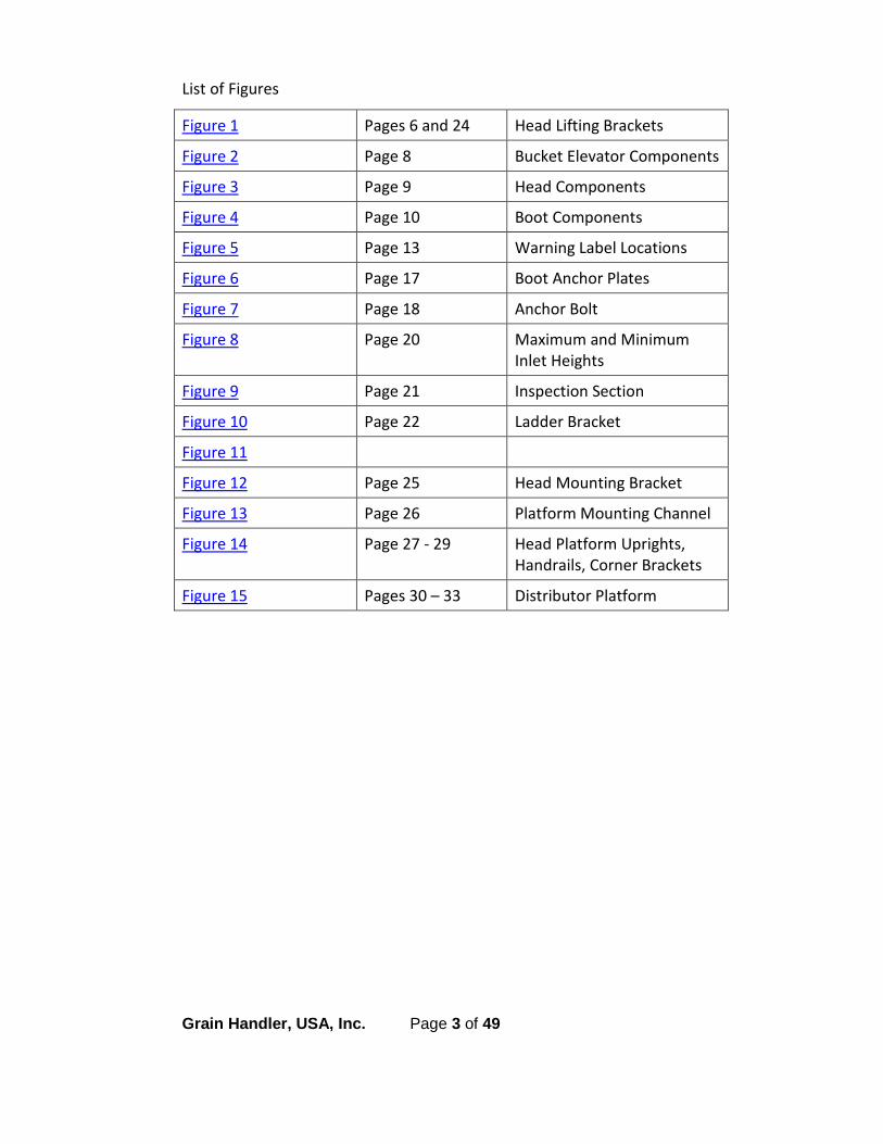
List of Figures
Figure 1 Pages 6 and 24 Head Lifting Brackets
Figure 2 Page 8 Bucket Elevator Components
Figure 3 Page 9 Head Components
Figure 4 Page 10 Boot Components
Figure 5 Page 13 Warning Label Locations
Figure 6 Page 17 Boot Anchor Plates
Figure 7 Page 18 Anchor Bolt
Figure 8 Page 20 Maximum and Minimum Inlet Heights
Figure 9 Page 21 Inspection Section
Figure 10 Page 22 Ladder Bracket
Figure 11
Figure 12 Page 25 Head Mounting Bracket
Figure 13 Page 26 Platform Mounting Channel
Figure 14 Page 27 - 29 Head Platform Uprights, Handrails, Corner Brackets
Figure 15 Pages 30 – 33 Distributor Platform
Grain Handler, USA, Inc. Page 4 of 49
Introduction Thank you for choosing Grain Handler, USA, Inc. as the manufacturer of your
new bucket elevator. We are pleased to have you as a customer and expect
that you will enjoy many years of productive service from our product. Your
Grain Handler bucket elevator has been designed to perform to a
predetermined capacity. It must be correctly installed, maintained and
operated in order to meet that capacity. This manual is designed to assist
you during the installation process and with operation procedures.
Grain Handler offers bucket elevators with a capacity range from 2,000 to
15,000 BPH.
Options may include: service and rest platforms, ladder with cage, explosion
vents on trunk, drive backstop, PVC belt, double or custom inlets. This
manual contains general information intended to assist in the installation,
startup, and maintenance of our standard bucket elevators. Details related
to options that you may have on your specific unit that are not covered in
this manual may be obtained from your Dealer or by contacting Grain
Handler directly.
This manual suggests an outline of how a bucket elevator can be erected,
however the specific method of installing it can partially depend on its size
and height as well as the proximity to other structures and obstacles. Only
qualified contractors should install this equipment. Grain Handler does not
take any responsibility for the installation of this equipment. The
responsibility of the proper installation lies with the installing contractor or
Dealer. If the installer requires further assistance or advice they should
contact the Dealer or Grain Handler.

Grain Handler, USA, Inc. Page 5 of 49
Service Inquiries
Identifying the specific piece of equipment is important when making
inquiries regarding installation, operation, maintenance, warranty or parts.
Record the following information and keep it handy if you need to contact
your Dealer.
Dealer Name:
Office / Cell Phone:
Local Service Tech’s Name:
Office / Cell Phone:
Sales Order #: Purchase Date:
Installation Date:
Model (capacity and height):
Inspecting and Verifying the Shipment
At the time of delivery, verify and inspect the quantity and condition of all
the parts. Compare items to
the packing list provided with
the shipment. Hardware,
including bolts, nuts, screws
and other small clips or
brackets may be divided into
smaller packages.
In case of any shortage or
damage during shipment, note detail of the shortage or damage on the ‘Bill
of Lading’ before you sign the shipment paperwork. File a claim with the
carrier and also notify your Dealer.
Parts that are short or damaged are the responsibility of the delivering
carrier, not the manufacturer or dealer.
Grain Handler, USA, Inc. Page 6 of 49
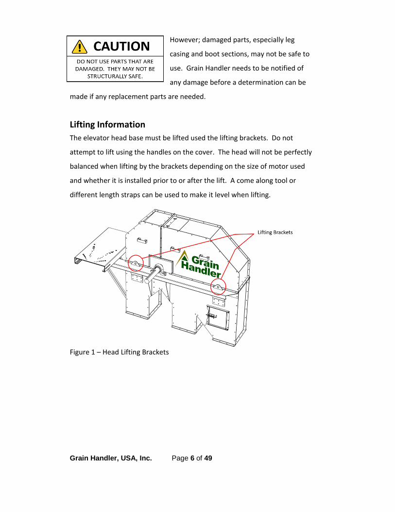
However; damaged parts, especially leg
casing and boot sections, may not be safe to
use. Grain Handler needs to be notified of
any damage before a determination can be
made if any replacement parts are needed.
Lifting Information The elevator head base must be lifted used the lifting brackets. Do not
attempt to lift using the handles on the cover. The head will not be perfectly
balanced when lifting by the brackets depending on the size of motor used
and whether it is installed prior to or after the lift. A come along tool or
different length straps can be used to make it level when lifting.
Figure 1 – Head Lifting Brackets

Grain Handler, USA, Inc. Page 7 of 49
Bucket Elevator Section
18” 2,000 –
3,000 BU
24” 3,750 –
5,500 BU
30” 5,500 –
7,500 BU
36” 8,000 –
11,000 BU
42” 12,500 –
15,000 BU
Boot Weight 600 Lbs. 272 Kg
912 Lbs. 414 Kg
1,010 Lbs. 458 Kg
1,210 Lbs. 549 Kg
1,650 Lbs. 748 Kg
Trunk Weight
(per 10 feet)
390 Lbs. 177 Kg
490 Lbs. 222 Kg
490 Lbs. 222 Kg
620 Lbs. 281 Kg
750 Lbs. 340 Kg
Head Weight
810 Lbs. 367 Kg
1,310 Lbs. 594 Kg
1,560 Lbs. 708 Kg
1,960 Lbs. 889 Kg
3,190 Lbs. 1,447 Kg
Head Platform
1,100 Lbs. 499 Kg
1,210 Lbs. 549 Kg
1,320 Lbs. 599 Kg
1,380 Lbs. 626 Kg
1,430 Lbs. 648 Kg.
Distributor Platform
440 Lbs. 200 Kg
440 Lbs. 200 Kg
440 Lbs. 200 Kg
550 Lbs. 250Kg
550 Lbs. 250Kg
Motor Weights
3 – 5 Hp 7.5 – 10 Hp 15 – 20 Hp 25 – 30 Hp
Aluminum 59 – 66 Lbs 27 – 30 Kg
102 – 114 Lbs 46 – 52 Kg
166 – 185 Lbs 75 – 84 Kg
NA
Cast Iron 88 – 94 Lbs 40 – 43 Kg
143 – 151 Lbs. 65 – 69 Kg
227 – 246 Lbs. 103 – 112 Kg
390 – 408 Lbs. 177 – 185 Kg
Gearbox Weights
Weights below are for Cleveland units. Specific model depends on size of your bucket elevator and will be listed on the packing slip. CGUSM4 CGUSM5 CGUSM6 CGSM7 CGSM8 CGSM9 139 Lbs. 63 Kg
207 Lbs. 94 Kg
285 Lbs. 129 Kg
462 Lbs. 210 Kg
633 Lbs. 287 Kg
760 Lbs. 345 Kg

Grain Handler, USA, Inc. Page 8 of 49
Bucket Elevator Components
Figure 2 – Bucket Elevator Components
Grain Handler, USA, Inc. Page 9 of 49
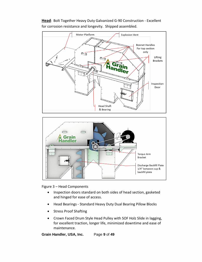
Head: Bolt Together Heavy Duty Galvanized G-90 Construction - Excellent for corrosion resistance and longevity. Shipped assembled.
Figure 3 – Head Components • Inspection doors standard on both sides of head section, gasketed
and hinged for ease of access.
• Head Bearings - Standard Heavy Duty Dual Bearing Pillow Blocks
• Stress Proof Shafting
• Crown Faced Drum Style Head Pulley with SOF Holz Slide in lagging, for excellent traction, longer life, minimized downtime and ease of maintenance.
Grain Handler, USA, Inc. Page 10 of 49
• Lined bonnet section with ¼” UHMW at weathertight points. Other lining options available: Urethane, or AR200
• Explosion vent on bonnet for pressure release
Trunk:
• Trunking – 12 ga. is standard on 42’ and optional on 18’, 24’, 30’ and 36’
• Belt – Rubber belt is standard, PVC is available upon request
• Explosion vents on trunk are available upon request
Drive:
• Standard is Cleveland, class 2; Dodge or other drives available upon request.
• Backstop is available upon request.
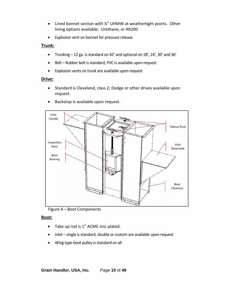
Figure 4 – Boot Components
Boot:
• Take up rod is 1” ACME zinc plated.
• Inlet – single is standard, double or custom are available upon request
• Wing type boot pulley is standard on all

Grain Handler, USA, Inc. Page 11 of 49
Safety Guidelines It is the responsibility of the owner/operator to know what requirements
precautions and specific hazards exist and make these known to all personnel
working with the equipment or in the area. Failure to read this manual and
follow the safety guidelines can cause misuse of the equipment and may lead
to serious injury or death.
ALERT: This is a safety alert sign. It is used to help identify safety hazards that could injure or kill if not avoided.
DANGER: Indicates an imminently hazardous situation which, if not avoided, will result in death or serious injury.
WARNING: Indicates a potentially hazardous situation which, if not avoided, could result in minor or moderate injury.
CAUTION: Indicates a potentially hazardous situation which, if not avoided, may result in minor or moderate injury.
Safety Responsibilities
Always operate equipment in accordance with these instructions and those
contained on the caution labels affixed to the equipment.
The Bucket Elevator must not be operated unless all covers and/or guards for the leg and drive unit are in place.
If you need to open the leg for inspection, cleaning, maintenance or observation, the electric power to the motor driving the leg must be LOCKED OUT in such a manner that it cannot be restarted by anyone, however remote the area, until the leg covers or guards have been properly replaced.
All ROTATING equipment such as drives, gears, shafts and couplings must be guarded by the purchaser/owner as required by applicable laws, standards and good practices.

Grain Handler, USA, Inc. Page 12 of 49
Do not attempt to clear a jammed piece of equipment until power has been LOCKED OUT.
Feed openings for shovel or front end loaders shall be constructed in such a way that the opening is covered by a grating.
Do not attempt any maintenance or repairs of the equipment until power has been locked out.
Do not place hands, feet or any part of your body in the equipment.
Do not use equipment for any purpose other than it is intended.
Keep area around equipment control station free of debris and obstacles and maintain good lighting around all equipment.
Eliminate all sources of stored energy (materials or devices that could cause the equipment to move without power applied) before opening the equipment.
Do not attempt field modification of equipment or components.
Do not be limited to these safety guidelines.
Safety Decals
Labels have been put on the bucket elevator. Do not remove, deface or paint
over them. Contact Grain Handler if replacements are needed

Grain Handler, USA, Inc. Page 13 of 49
Warning Label Locations
Figure 5 – Warning Label Locations

Grain Handler, USA, Inc. Page 14 of 49
Hardware & Tools 1/2 Impact Socket Set: 3/8 to 1-1/8
Alignment Punches: Two – 3/16 point punches per install person
Allen Sets: Large and small sets are necessary as there are many different sizes needed for set screws and electrical main breakers
Bits: Ten 5/16 bits and Five 3/8 bits Bolt & Nut Apron: One per installer
Carpet Knife: Or Saw for cutting the belt Climbing: Safety harnesses with three way lanyards
Come Along Winch: Four, two ton Cordless Impact
Wrench: 1/2" with 1/2” socket (one per installer)
Drill: 5/16”bit (one per installer) Extension Cords: Two 100’ and two 50’
Hammer Drill: 3/4” and 1/2" bits Hammers: One sledge, dead blow and assorted smaller
Impact Socket Wrench: 3/4” Ladders: Two 12’
Level: One 48” Metal Saw: One Nut Driver: Three 5/16 and three 3/8
Pipe Wrenches: Two 36” Power Tools: Drill, Impact Wrench, Grinder
Screw Drivers: Phillips size #2, Flat head Small, Medium & Large; Jewelers size flat head
Tag Lines: Two 100’ Spreader Bar: To bolt to belt for initial installation
Square (framing): 54” Tape Measure One 100’ and One 25’ Tool lanyards: Two per outside and inside installer
Vice Grips: Two regular and Two C Clamp Style
Welder: With generator and welding clamps Winch: For pulling belt
Wrenches / Sockets: 1-1/8”, 3/4”, 9/16”, 1/2” (per installer), 7/16”, 3/8”, 1/4”, 3/16”, 5/32”, 1/8”, 3/32 crescent

Grain Handler, USA, Inc. Page 15 of 49
Preparation
Electrical
Check local codes before installation. Electrical work must be done by a
qualified electrician in accordance with all applicable electrical codes.
When using this piece of equipment in conjunction with other pieces of
equipment, the system needs to be interconnected. It should be designed so
when any one piece of equipment shuts down or fails, the preceding
equipment will also stop. This can help avoid injury and unnecessarily
damaging other equipment.
Use lock out/ tag out whenever performing service on the equipment.
A disconnect switch must be provided and located as close as possible to the bucket elevator and at the top near the motor.
Check rotation before using.
Structural System
This bucket elevator is designed to support its own vertical weight, but must
be laterally supported. There are 3 common methods that are used for
support:
1. A system of guy cables.
2. Brace to nearby capable structures.
3. A tower system.
Consult a qualified structural engineer to determine how this can best be done. Keep in mind the bucket elevator is not designed to handle the additional
load of distributers or other equipment. That equipment must be
independently supported.

Grain Handler, USA, Inc. Page 16 of 49
Concrete Design and Construction
Grain Handler recommends that you consult with a local Civil Engineer for
concrete specifications as soil conditions, environments and regulations will
change by location. Using soil borings to determine the allowable soil
bearing capacity, a professional engineer will need to be consulted to design
the foundation slab. Grain Handler recommends a minimum of 4,000 PSF
soil. All suggested foundation designs must be approved by a licensed
engineer in order to meet local governing building codes and local soil and
weather conditions.
The finished floor surface must be level at the base plate location.
Low spots without adequate shimming can cause structural
damage to the Grain Leg and create safety issues. Faulty concrete
or missing shims will void the warranty.
Boot Location
Plan the exact location of the boot. The bucket elevator will need to have
enough access that it can be properly spouted and fed. Make sure there is
enough room around the bucket elevator for future service.
Elevator Foundation
The footing must be designed by a qualified structural engineer. The footing
must be capable of supporting weight of the leg, weight of the product, and
wind loads among other factors. Consideration should also be taken for rain
and snow runoff.

Grain Handler, USA, Inc. Page 17 of 49
Assembling the Leg This equipment should be installed by
skilled millwrights.
Stage Components
Components should be staged in the order in which they will be installed.
Pre-assembling some sections of leg casing can save crane time.
Setting the Boot
The boot is shipped fully assembled. The entire weight of the leg,
including accessories and the weight of the grain in transit is supported
by the boot section. The boot must be fixed securely to an engineered
concrete base. Mounting plates are built into the boot section.
Figure 6 – Boot Anchor Plates
Grain Handler, USA, Inc. Page 18 of 49
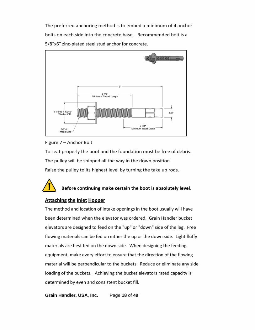
The preferred anchoring method is to embed a minimum of 4 anchor
bolts on each side into the concrete base. Recommended bolt is a
5/8”x6” zinc-plated steel stud anchor for concrete.
Figure 7 – Anchor Bolt
To seat properly the boot and the foundation must be free of debris.
The pulley will be shipped all the way in the down position.
Raise the pulley to its highest level by turning the take up rods.
Before continuing make certain the boot is absolutely level.
Attaching the Inlet Hopper
The method and location of intake openings in the boot usually will have
been determined when the elevator was ordered. Grain Handler bucket
elevators are designed to feed on the "up" or "down" side of the leg. Free
flowing materials can be fed on either the up or the down side. Light fluffy
materials are best fed on the down side. When designing the feeding
equipment, make every effort to ensure that the direction of the flowing
material will be perpendicular to the buckets. Reduce or eliminate any side
loading of the buckets. Achieving the bucket elevators rated capacity is
determined by even and consistent bucket fill.

Grain Handler, USA, Inc. Page 19 of 49
Upside Feed: When attaching the inlet to the upside it should be installed all
the way up on the boot or at least so the bottom of the inlet is at, or above
the centerline of the pulley. The device which feeds the elevator, (auger,
belt conveyor, spout, hopper, etc.), must feed the material into the boot
ABOVE the centerline of the pulley. The buckets must complete the turn
around the pulley and be moving vertically upward, not at an angle, before
encountering the material to be elevated. If the buckets ARE NOT moving
vertically upward when they pick up the incoming material, material will be
forced back into the infeed device or chute. Grinding and churning in the
boot area will damage the product and excessive power will be required to
operate the system; and capacity will be reduced.
Downside Feed: When attaching the inlet to the downside, it should be
installed as far down on the boot as possible or just above the clean out
door.
Discharge: Spouting to carry off the material must be sized so that its
capacity equals or exceeds the maximum capacity of the elevator to prevent
material plugging in the head or back legging. The bucket elevator is NOT
designed to support the weight of any accessory equipment. Spouting,
cleaners, distributors, etc. must have their own supporting structures.
NOTE: You may choose to attach the inlet hopper toward the end of the
project to avoid having to work around it as the other sections are installed.

Grain Handler, USA, Inc. Page 20 of 49
Figure 8 – Maximum and Minimum Inlet Heights
The boot must be securely fixed before any trunking can be installed.
Grain Handler, USA, Inc. Page 21 of 49
Installing the Trunk Sections
Check the quantity and length of each trunk section before starting. The
trunk sections should be arranged in the order in which they will be installed.
The trunk sections are shipped in as many ten foot sections as possible with a
five foot heavy gauge inspection section at the bottom; and a custom length
section depending on the finished discharge height requested.
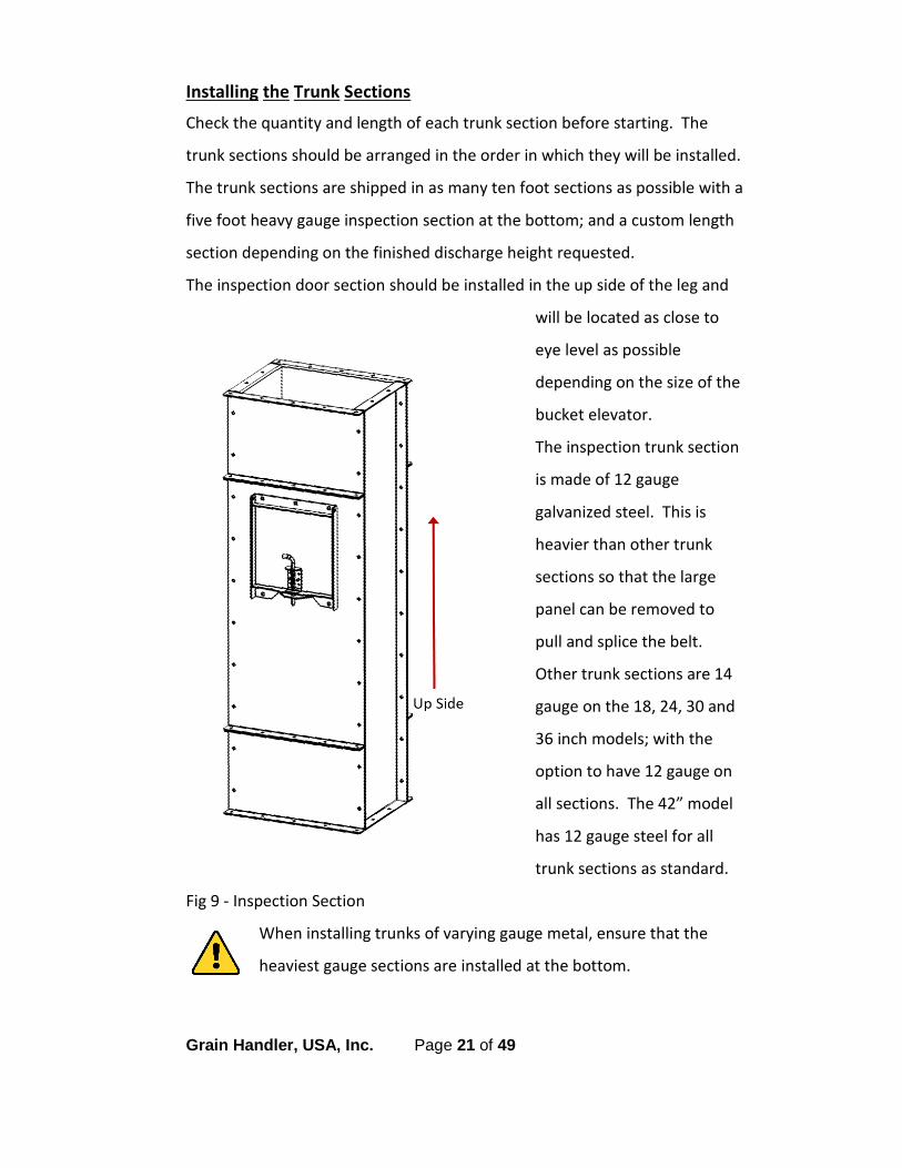
The inspection door section should be installed in the up side of the leg and
will be located as close to
eye level as possible
depending on the size of the
bucket elevator.
The inspection trunk section
is made of 12 gauge
galvanized steel. This is
heavier than other trunk
sections so that the large
panel can be removed to
pull and splice the belt.
Other trunk sections are 14
gauge on the 18, 24, 30 and
36 inch models; with the
option to have 12 gauge on
all sections. The 42” model
has 12 gauge steel for all
trunk sections as standard.
Fig 9 - Inspection Section
When installing trunks of varying gauge metal, ensure that the
heaviest gauge sections are installed at the bottom.

Grain Handler, USA, Inc. Page 22 of 49
Each section of the trunk must be plumb, level and straight as it is installed.
It is common to find minor deviations in these types of fabricated assemblies.
Most often they can be corrected by rotating the section 180° or turning end
for end. If this does not solve an out of level or out of plumb condition it will
be necessary to use metal shims and caulk the resulting gap. When a gap
occurs in a corner of the casing, metal shims should be used and should
extend a minimum of six inches in both directions. Insure that shims do not
project inside of casing. Each intermediate section must be plumbed to less
than 1/8" deviation before proceeding to the next section. Casings must be
braced or anchored to a rigid structure every 20 feet and not more than 4
feet below the head section. If a rigid structure is not available, guy wires
may be used with the same spacing. The leg needs to be laterally
supported as it is assembled. Cross braces should be installed on top of the
trunking flanges. The bolts should be tightened evenly making sure the
trunk is not twisting. Plumb trunk sections in all directions as they are
assembled and check again when the installation is complete.
Ladder
brackets
bolt onto
the braces
using pre-
punched
holes.
Fig 10 – GH6510 Ladder Bracket

Grain Handler, USA, Inc. Page 23 of 49
If you have ordered trunking with the optional explosion vents, contact
your Dealer or Grain Handler for correct placement of those sections.
Ladder and Safety Cage
Optional ladder and safety cages bolt onto the tie braces and can be installed
as the leg is erected. The configuration of your site determines whether a
ladder is needed. For example, if you have two bucket elevators side by side,
only one ladder is needed. If you have a tower with stairs and work
platforms, no separate ladder would be needed for the bucket elevator.
The ladders and cages are shipped in 10 foot sections (or custom length
sections depending upon the size of your bucket elevator). Each section is
attached on site.
A length of ladder will lead up to a platform and extend upward through the
platform opening to the level of the platform's top rail.
The total lengths of safety cage will not equal the total lengths of ladders
when rest platforms are used. The bottom edges of the hoops are spaced
approximately 7 feet above the floor level of the platforms.
The bottom of the ladder, whether at ground or grade level, should
be surrounded by a lockable safety cage or otherwise arranged to
prohibit access to unauthorized personnel.
Grain Handler, USA, Inc. Page 24 of 49
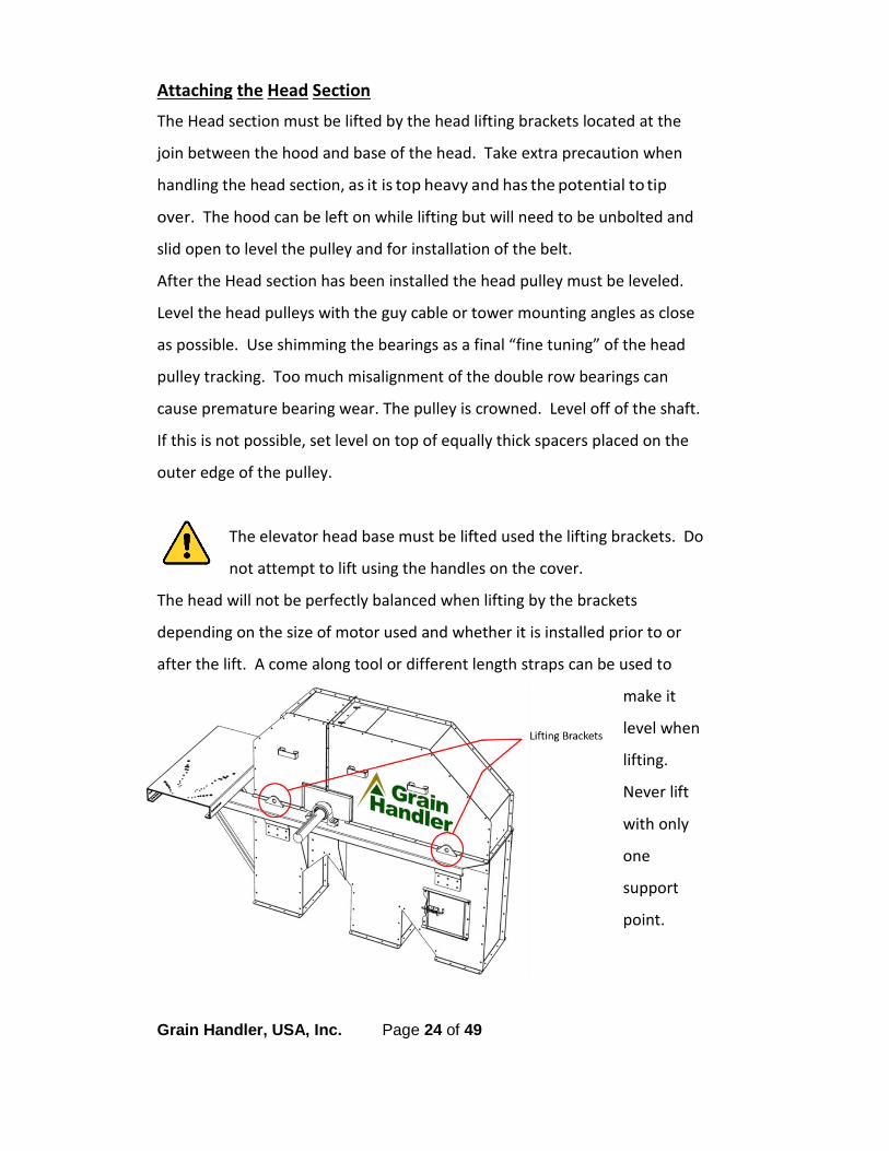
Attaching the Head Section
The Head section must be lifted by the head lifting brackets located at the
join between the hood and base of the head. Take extra precaution when
handling the head section, as it is top heavy and has the potential to tip
over. The hood can be left on while lifting but will need to be unbolted and
slid open to level the pulley and for installation of the belt.
After the Head section has been installed the head pulley must be leveled.
Level the head pulleys with the guy cable or tower mounting angles as close
as possible. Use shimming the bearings as a final “fine tuning” of the head
pulley tracking. Too much misalignment of the double row bearings can
cause premature bearing wear. The pulley is crowned. Level off of the shaft.
If this is not possible, set level on top of equally thick spacers placed on the
outer edge of the pulley.
The elevator head base must be lifted used the lifting brackets. Do
not attempt to lift using the handles on the cover.
The head will not be perfectly balanced when lifting by the brackets
depending on the size of motor used and whether it is installed prior to or
after the lift. A come along tool or different length straps can be used to
make it
level when
lifting.
Never lift
with only
one
support
point.
Grain Handler, USA, Inc. Page 25 of 49
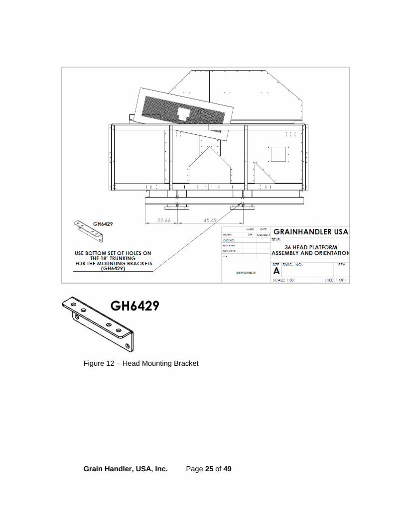
Figure 12 – Head Mounting Bracket
Grain Handler, USA, Inc. Page 26 of 49
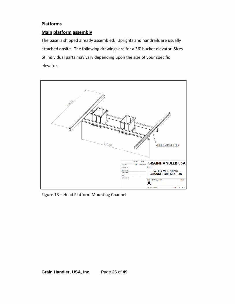
Platforms
Main platform assembly
The base is shipped already assembled. Uprights and handrails are usually
attached onsite. The following drawings are for a 36’ bucket elevator. Sizes
of individual parts may vary depending upon the size of your specific
elevator.
Figure 13 – Head Platform Mounting Channel

Grain Handler, USA, Inc. Page 27 of 49
Figure 14 – Head Platform Uprights, Handrails, Corner Brackets
Grain Handler, USA, Inc. Page 28 of 49
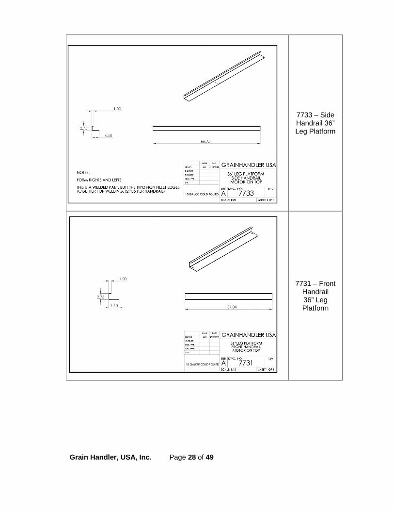
7733 – Side Handrail 36” Leg Platform
7731 – Front Handrail 36” Leg Platform

Grain Handler, USA, Inc. Page 29 of 49
7165 – Handrail Upright
Main Platform support cross channels are bolted to the trunk and platform.

Grain Handler, USA, Inc. Page 30 of 49
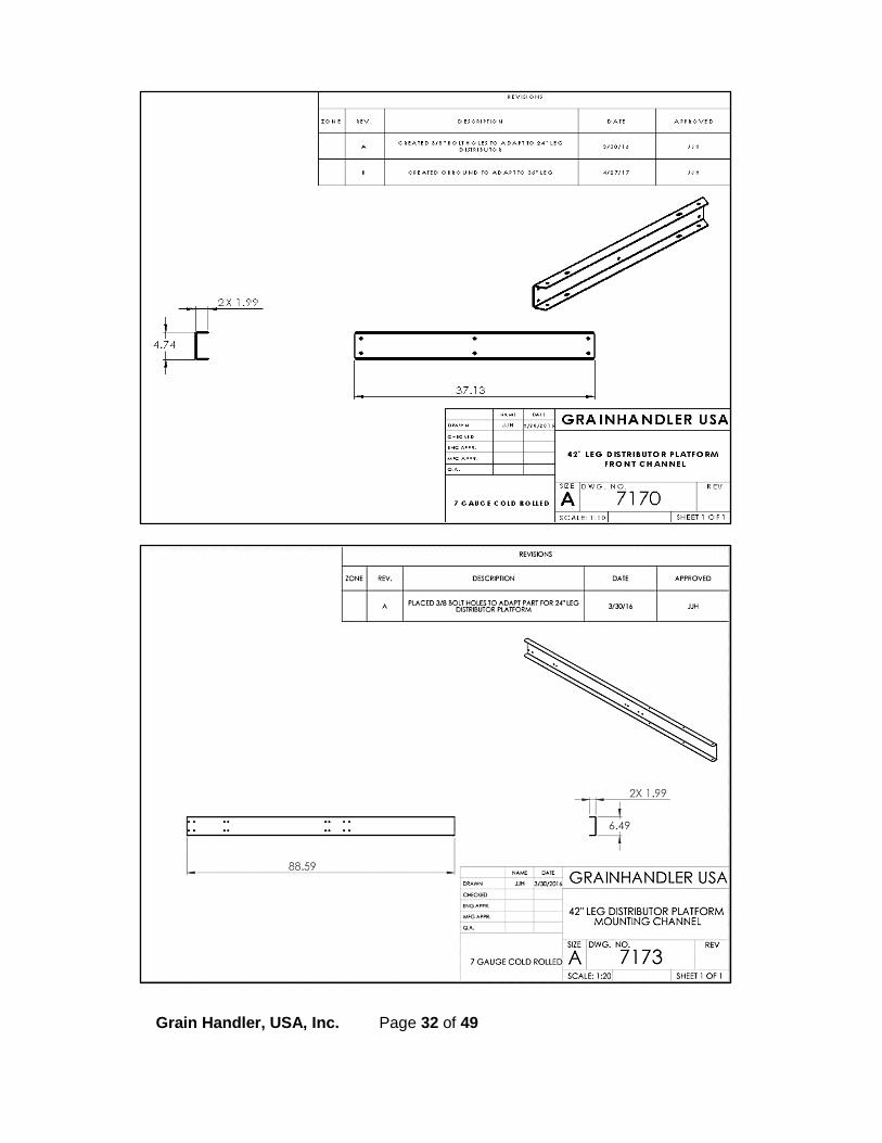
Distributor Platform
Base will be shipped already assembled. Uprights and handrails will be
assembled onsite. The following drawings are for 36’ and 42’ bucket
elevators. Sizes of individual parts may vary depending upon the size of your
specific elevator. It is important that a strong support be installed under the
distributor before installing spouting, distributor controls, etc. The added
weight of spouting hanging from the distributor can pull the elevator casing
out of plumb and cause damage to casing if extra support under the
distributor is not provided. It is suggested that a tower or similar structure
be used for support. Spout arrangement should be carefully planned to
avoid uneven weight distribution.
Note: Be certain to allow ample distance between the platform and the
distributor to allow for easier servicing.
Figure 15 – Distributor Platform

Grain Handler, USA, Inc. Page 31 of 49
Grain Handler, USA, Inc. Page 32 of 49

Grain Handler, USA, Inc. Page 33 of 49
Standoff platform option

Grain Handler, USA, Inc. Page 34 of 49
Installing the Buckets and Belt
Belt option materials include 2 and 3 ply rubber or PVC. This will be specified
with your order. If you have chosen to source your own belt, contact your
Dealer or Grain Handler for specifications.
Buckets are made of High Density Polyethelylene. Steel or other bucket
materials are available as options upon request. Holes are pre-drilled and
match those on the belt. The size is specified with your order based on the
size of the bucket elevator.
Choose a plan to install the belt and cups. On shorter legs (less than 100
feet) it may be easier to install the cups onto the belt prior to installing the
belt, however, this will make the belt heavier and more difficult to handle.
With taller legs it may become necessary to install the belt first and then bolt
the cups on. This is left to the discretion of the contractor. The choice of
methods used to install the belt and buckets is determined by:
a. length and weight of belt,
b. number, size, and weight of buckets,
c. open area available around the base of the elevator, and
d. available equipment.

Grain Handler, USA, Inc. Page 35 of 49
General Steps:
1. Adjust the boot take up rods to the raise the pulley to its highest level.
2. The installer should fabricate a spreader bar that will be used to connect a haulage line to pull the belt. A bar is recommended rather than simply punching a hole in the belt and tying or clamping the line to the belt.
3. Rig a rope or cable through the removable panel in the UP leg through which the belt; or belt with buckets attached, will be pulled into the elevator. The line is then hauled up the UP leg, over the head pulley, and down the DOWN elevator leg. Usually, the line can be passed around the boot takeup pulley and out of a cleanout panel to a winch so the belt can be pulled into the elevator.
4. Place a flat table in-line with an opening in the Up leg trunk of the elevator, usually the end panel in the boot section. Remove the boot end panel.
5. Arrange the roll of belt so it can easily be unrolled onto the worktable and then into the elevator's UP leg. Rubber belts will be the same on both sides. PVC belts have a ‘glossy’ side that should be facing outward where the cups are attached.
6. The belt will already have the bucket mounting holes pre-punched in the correct pattern and spacing. The heads of the elevator bolts bear against the inside surface of the belt. Buckets are to bear against the opposite or outer surface of the belt. Elevator bolts should be tightened so as to draw the heads flush with the belt surface. This prevents the bolt heads from scarring the pulleys or working loose.
Grain Handler, USA, Inc. Page 36 of 49
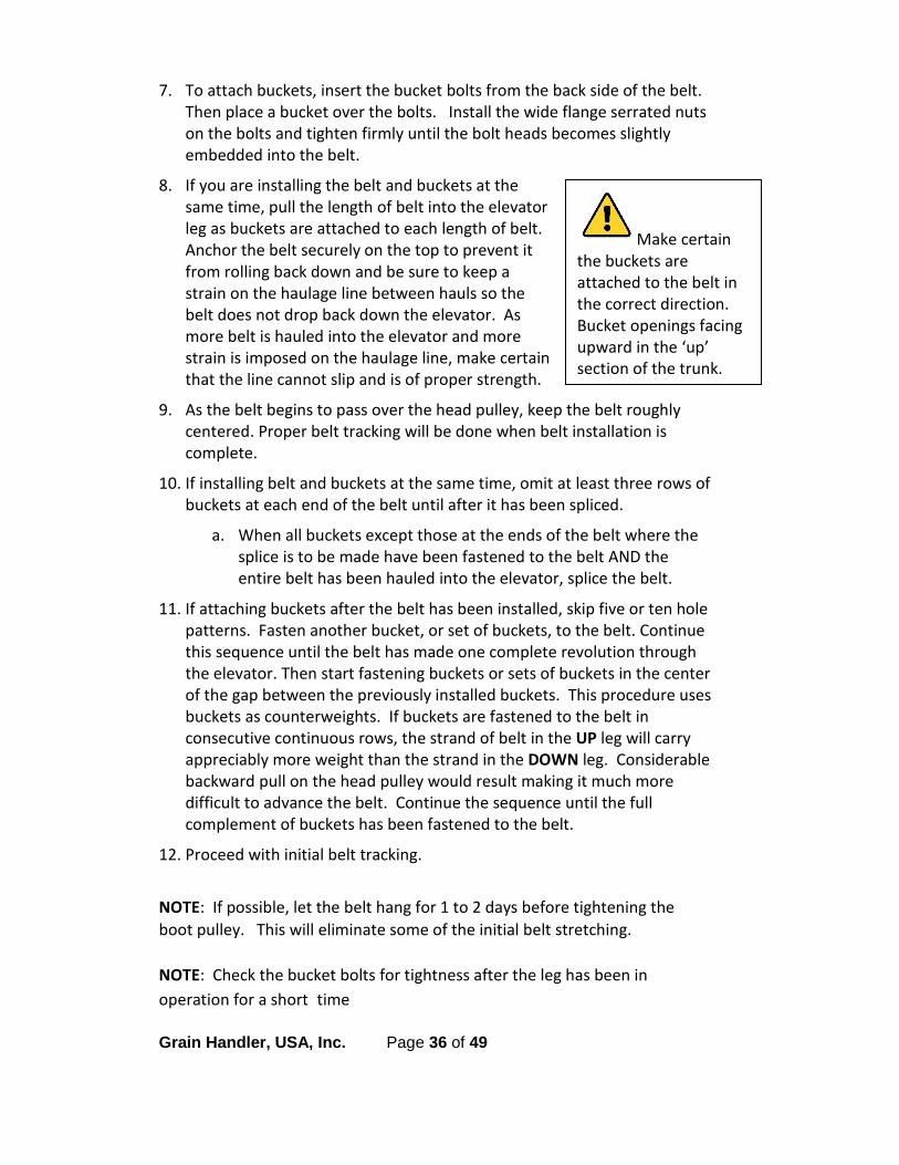
7. To attach buckets, insert the bucket bolts from the back side of the belt. Then place a bucket over the bolts. Install the wide flange serrated nuts on the bolts and tighten firmly until the bolt heads becomes slightly embedded into the belt.
8. If you are installing the belt and buckets at the same time, pull the length of belt into the elevator leg as buckets are attached to each length of belt. Anchor the belt securely on the top to prevent it from rolling back down and be sure to keep a strain on the haulage line between hauls so the belt does not drop back down the elevator. As more belt is hauled into the elevator and more strain is imposed on the haulage line, make certain that the line cannot slip and is of proper strength.
9. As the belt begins to pass over the head pulley, keep the belt roughly centered. Proper belt tracking will be done when belt installation is complete.
10. If installing belt and buckets at the same time, omit at least three rows of buckets at each end of the belt until after it has been spliced.
a. When all buckets except those at the ends of the belt where the splice is to be made have been fastened to the belt AND the entire belt has been hauled into the elevator, splice the belt.
11. If attaching buckets after the belt has been installed, skip five or ten hole patterns. Fasten another bucket, or set of buckets, to the belt. Continue this sequence until the belt has made one complete revolution through the elevator. Then start fastening buckets or sets of buckets in the center of the gap between the previously installed buckets. This procedure uses buckets as counterweights. If buckets are fastened to the belt in consecutive continuous rows, the strand of belt in the UP leg will carry appreciably more weight than the strand in the DOWN leg. Considerable backward pull on the head pulley would result making it much more difficult to advance the belt. Continue the sequence until the full complement of buckets has been fastened to the belt.
12. Proceed with initial belt tracking.
NOTE: If possible, let the belt hang for 1 to 2 days before tightening the boot pulley. This will eliminate some of the initial belt stretching.
NOTE: Check the bucket bolts for tightness after the leg has been in operation for a short time
Make certain the buckets are attached to the belt in the correct direction. Bucket openings facing upward in the ‘up’ section of the trunk.

Grain Handler, USA, Inc. Page 37 of 49
Splicing the Belt
There are numerous types of splices. The Grain Handler standard is the "Lap
Splice"
The boot pulley must be raised to its highest position by turning the take up
rods. Using hand winches or come-a-longs, tighten the belt to remove slack
before splicing. The lap splice should overlap by a minimum of 6 cups. The
belt should be bolted together with the factory supplied longer cup bolts.
Larger bolts are used to attach buckets where the belt is spliced.
After belt splicing is complete and buckets have been attached, re-connect
the hood section of the head.
Assembling the Drive
The installing contractor is responsible to check the drive to meet or exceed
all local safety and electrical codes regardless if the drive is furnished with
the leg or not. If the drive is supplied by Grain Handler, the proper Torque
Arm Mount and Guard will be supplied with the bucket elevator. If it
supplied by others, the contractor or owner are responsible. The Contractor
must verify that all of the drive manufacturer's instructions have been
followed prior to startup.
If the motor and drive are supplied by Grain Handler it will be shipped
assembled on the head section and filled with the proper lubrication, there
will be a tag on the gearbox stating the date and the type of lubrication. If
the backstop needs to be removed from the drive prior to operation to roll
the belt back or for any reason; a small amount of oil will leak out of the
drive. The oil should be captured in a clean container and put back in the
drive or measured and the same amount and type replaced.
Damage resulting from running the gearbox without lubrication will not be
covered by the gearbox manufacturer or Grain Handler. If a
backstop is required care must be taken to assemble it in the
correct rotation.

Grain Handler, USA, Inc. Page 38 of 49
Before the belts are installed turn the gearbox input shaft by hand to verify
the pulley rotation. The motor needs to be tested for proper rotation before
the belts are installed. Reverse rotation can cause damage to internal bucket
elevator and / or drive components.
Install and tension the belts using the motor adjustment rods located on back
of the head section. Normal belt tension is 1/64" of deflection per 1" of
sheave centers on one side of the belt centered between the sheave.
Check belt tension frequently during the first 48 hours of operation.
Tracking the Belt
Initial tracking should be done when the bucket elevator is empty. The belt
should center on the crowned pulleys whether empty or under load. If it
isn't, check the head pulley first. When centered, adjust the boot pulley. If
the condition persists, check the following list of possible causes:
1. The pulleys are not centered in the head or boot. 2. The leg is not plumb. 3. The head shaft is not level. 4. The head shaft is not square to the back of the head. 5. The belt splice is not square. 6. There is too little belt tension. 7. The pulley hubs are not properly seated causing pulley wobble.
Belt Adjustment
All new belts will stretch. The amount of stretch depends on type and length
of the belt. Belt tension may have to be adjusted numerous times during
early operation of the leg. It may even be necessary to shorten the belt
several times. If the belt stretch exceeds the take ups travel, the belt must
be shortened.
Belt Tension
The belt tension needs to be sufficient enough to prevent the belt from
slipping at the head pulley. It also needs to be tight enough to prevent
discharge of the cups in the up leg. If the belt tracks properly and does not
slip when the elevator is operating at maximum capacity, then the belt is

Grain Handler, USA, Inc. Page 39 of 49
sufficiently tensioned. Tension adjustment, however, must wait until the
entire installation is complete and material (the product; grain, etc.) can be
conveyed to and from the elevator.
The belt can be tensioned by comparing the Revolutions Per Minute (RPM) of
the boot shaft to that of the head shaft. Check this under load and running
empty. Belt slip is most often detected by observing the bearing setscrews
on the head and tail shafts while counting the number of revolutions of
pulley in the same period of time, typically 30 to 60 seconds.
• If the head and boot pulley are the same diameter, then the RPM of the boot shaft will be slightly greater (1-2 RPM) because the lagging on the head increases the diameter of the pulley.
• If the boot pulley is smaller in diameter than the head, then the boot shaft RPM will be substantially greater.
If the belt is slipping and all other conditions appear to be normal, adjust the
takeup.
Verify that the belt continues to track the center of the head and boot
takeup pulleys. If it does not, check to see if the material being fed into the
elevator is entering at an angle and forcing the belt to one side of the pulley.
This condition, if it occurs, must be corrected. Continual lateral pressure on
the belt can cause the belt edge to rub against the elevator structure causing
rapid wear on the belt. More serious than wear, a fire and/or explosion can
occur if belt friction generates sufficient heat.
After the elevator has operated for a period of time, the takeup may require
readjustment to compensate for initial belt stretch. Depending upon the
amount of initial stretch, the belt may even have to be shortened and re-
spliced.

Grain Handler, USA, Inc. Page 40 of 49
Adjust the Throat Wiper
The wiper should be adjusted at the belt splice and with the belt centered on
the head pulley. Adjust the wiper with the bolts underneath to provide 1/4"
- 3/8" clearance from the tip of the buckets. Ensure that the clearance
accommodates the width of the spliced section of belt. Proper
adjustment will minimize one cause of back legging.
Running Product through the Leg Before using the bucket elevator for the first time, lubricate all components
requiring initial lubrication. This includes, but is not limited to, the drive
reducer.
Run the leg empty for several minutes before feeding it. Observe the belt as
it passes around the pulleys. If the belt appears to be "walking" towards the
edge of the pulley, be ready to shut down the elevator drive. Several
complete revolutions of the belt will be required before the belt reaches a
steady-state tracking condition. If the belt steadily tracks on or near the
center of both pulleys, no further action is necessary.
With the leg running, regulate the flow of material into the boot so that the
leg is operating at about 50% capacity. Continue to operate at 50% capacity
for several hours. After a trial run of several hours at 50% of capacity, the leg
may be run under full load.
1. Ensure that the flow or distribution system from the bucket elevator is connected and open.
2. Start the leg before feeding the inlet. Starting the leg under load is not recommended.
3. Gradually increase the flow of material into the boot until the amount entering the boot is equal to the amount that the bucket can take away.
4. Obtain proper bucket fill, but do not overfill the boot. This will not result in greater capacity. It will only put a greater strain on the drive, belt and buckets.

Grain Handler, USA, Inc. Page 41 of 49
Checking the Head Shroud
The head shroud is factory set. The leg should reach capacity without any
down legging. However, if the shroud adjustment was affected during
assembling or erecting of the leg, an adjustment may have to be made.
Avoid over-adjusting. Use increments of ¼"-½" up or down from preset
position until the leg is discharging without down legging.

Grain Handler, USA, Inc. Page 42 of 49
General Operating information Starting and Stopping the bucket elevator under normal operating
conditions:
• The leg should not be started under load nor should it be stopped with material still entering the boot.
• Always run the leg for a short time before feeding it. This is particularly important in cold weather. Frost may build up on pulleys, belts, bearings, etc... Running the leg empty briefly will correct this condition.
• Run the leg for a short period of time after the material flow has been shut off. The material in the buckets and boot (within reach of the buckets) should be discharged.
• If excess material remains in the boot after shut down or if the leg has been choked, the excess should be manually removed before the leg is started again.
It sometimes becomes necessary to shut off the leg before all the material is
discharged. Most legs will start under "normal load". "Normal", meaning the
usual amount of material in the buckets.

Grain Handler, USA, Inc. Page 43 of 49
Maintenance WARNING LOCK OUT & TAG OUT THIS EQUIPMENT BEFORE REMOVING ANY COVERS OR GUARDS
A regular program of inspection and maintenance is recommended to keep the Grain Handler bucket elevator in good operating condition. If more information is needed than what is supplied in this manual, please contact your local Dealer or Grain Handler.
Nuts and Bolts
• Check bucket bolts after a few days of operation and tighten nuts as required. On new installations, bolt heads will seat into the belt after a few days of operation thus permitting nuts to loosen.
• Inspect again after three or four weeks of operation to see if nuts have loosened. Continue this inspection at the same interval on units operated continuously.
Leg Belt
• Check the belt tension and belt tracking daily.
• Check for wear on the sides of the belt. This can indicate misalignment or material build up on the belt or pulleys.
• Check for scuffing and wear on back of belt. This usually indicates that the belt is slipping on the head pulley.
• A misaligned belt can work over and rub on the side quickly causing damage to the leg.
Cups
• Check the bucket bolts for tightness after the first 10 hours of operation. Most importantly, be sure to check the cups on the splice. Periodically re-check the bolts.
• Check the condition of the buckets. Replace as necessary.
Drive Belt Tension
• The drive belt must be kept properly tensioned. Do not over tighten. Check belt frequently during first 100 hours of operation.
Grain Handler, USA, Inc. Page 44 of 49
Head Pulley Lagging
• Using the lagging inspection door on side of the head base periodically inspect the lagging for damage. Replace as necessary.
Head and Boot Pulleys
• After the first 10 hours of operation, check the pulleys for proper alignment and retighten the taper lock hub bolts and bearing set screws.
• Periodically check pulleys for alignment.
• On installations that require the Elevator boot to be in direct exposure to extreme weather conditions, it is recommended that the take up bolts be liberally treated with lubricating oil or rust preventative. This will make the take-up operate more easily when necessary.
Throat Wiper
• Periodically inspect the throat wiper. It should be 1/4" - 3/8" away from the bucket when checked at the belt splice.
Drive Setup
• Periodically check the gearbox oil level.
• Periodically Inspect the bearing mounts, guards, taper lock hubs, bearings and sheaves to ensure that everything is in proper position.
Bearings
• The bearings must be inspected on a regular basis. A bad bearing can be a very dangerous situation and must be remedied immediately.
• Lube bearings periodically. Refer to the supplemental bearing manufacturer recommendations for the most common factory used bearings.
Lubrication
• Set up a regular lubrication schedule for the gearbox and motor to comply with the manufactures guidelines.
Audio inspection
• Become familiar with the sound of the leg in operation. A change in sound is often an early warning sign of a potential problem.

Grain Handler, USA, Inc. Page 45 of 49
Troubleshooting
Issue Possible Causes Solution
Belt not tracking on boot pulley
Take ups adjusted improperly
Level boot pulley and track belt to center of pulley
Belt too loose for pulley to guide belt
Tighten belt and track belt to center of pulley
Bad bearing Replace bearing
Product buildup on pulley Clean / may need self cleaning pulley for certain products.
Pulley is not crowned Replace pulley or install center lagging
Belt not tracking on head pulley
Head shaft not level Shim bearings until level
Belt splice is crooked Re-splice
Cups not filling evenly Fix inlet feed so cups fill evenly
Leg not plumb Re-check with transit and re-plumb
Pulley is not crowned Replace pulley or install center lagging
Bad bearing Replace bearing
Lagging worn or damaged Replace lagging
Grain Handler, USA, Inc. Page 46 of 49
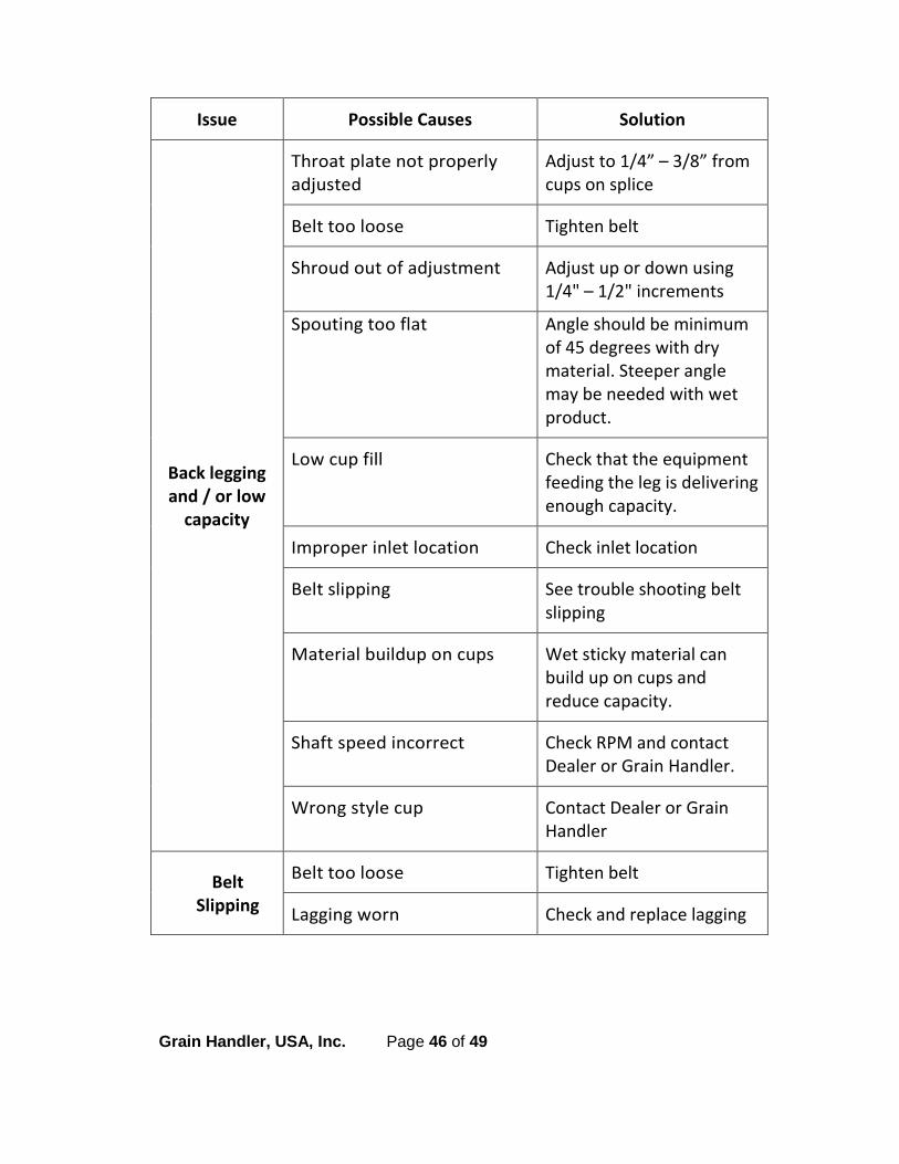
Issue Possible Causes Solution
Back legging and / or low
capacity
Throat plate not properly adjusted
Adjust to 1/4” – 3/8” from cups on splice
Belt too loose Tighten belt
Shroud out of adjustment Adjust up or down using 1/4" – 1/2" increments
Spouting too flat Angle should be minimum of 45 degrees with dry material. Steeper angle may be needed with wet product.
Low cup fill Check that the equipment feeding the leg is delivering enough capacity.
Improper inlet location Check inlet location
Belt slipping See trouble shooting belt slipping
Material buildup on cups Wet sticky material can build up on cups and reduce capacity.
Shaft speed incorrect Check RPM and contact Dealer or Grain Handler.
Wrong style cup Contact Dealer or Grain Handler
Belt Slipping
Belt too loose Tighten belt
Lagging worn Check and replace lagging

Grain Handler, USA, Inc. Page 47 of 49
Issue Possible Causes Solution
Boot pulley buildup
Sticky product A self cleaning pulley may be needed.
Damaged cups
Obstruction in leg Find and remove obstruction
Belt too loose Tighten belt
Leg out of plumb Re-check with transit and re-plumb
Cups pull loose from
belt or belt is torn at bolt
hole
Cups not bolted tightly Cup bolts should be kept tights. If bolts come loose, cup may snag or be torn from belt
Jammed boot Controlled feed should help eliminate jams and turbulence in the boot.
Motor cannot start leg
Backstop is reversed Re-install correctly
Motor rotation is wrong Contact electrician
Boot is full Leg was shut down too early, clean out
Overfeeding Reduce feed rate
Motor over-amps
Motor is incorrectly wired Check that motor is wired for correct voltage
Wrong size starter Check starter size
Motor is faulty Check and replace
Motor is too small Check amps and contact Dealer or Grain Handler

Grain Handler, USA, Inc. Page 48 of 49
Issue Possible Causes Solution
Excessive noise in boot
section
Belt not tracking Track belt using take-ups
Cups striking boot bottom Belt is too long. Re-splice belt.
Pulley slid on shaft and is rubbing on the side of the boot housing
Find out why the pulley moved and resolve.
Bad bearing Replace immediately
Excessive noise in head
section
Belt not tracking Track belt
Bad bearing Replace immediately
Pulley slid on shaft and is rubbing on the side of the head housing
Find out why the pulley moved and resolve.
Failed drive component Check gearbox and motor
Excessive noise in trunking
Obstruction in trunking Find obstruction and remove
Cups hitting because of loose belt
Tighten belt
Leg not plumb Re-check with transit and re-plumb
Belt splice crooked Re-splice belt
Grain Handler, USA, Inc. Page 49 of 49
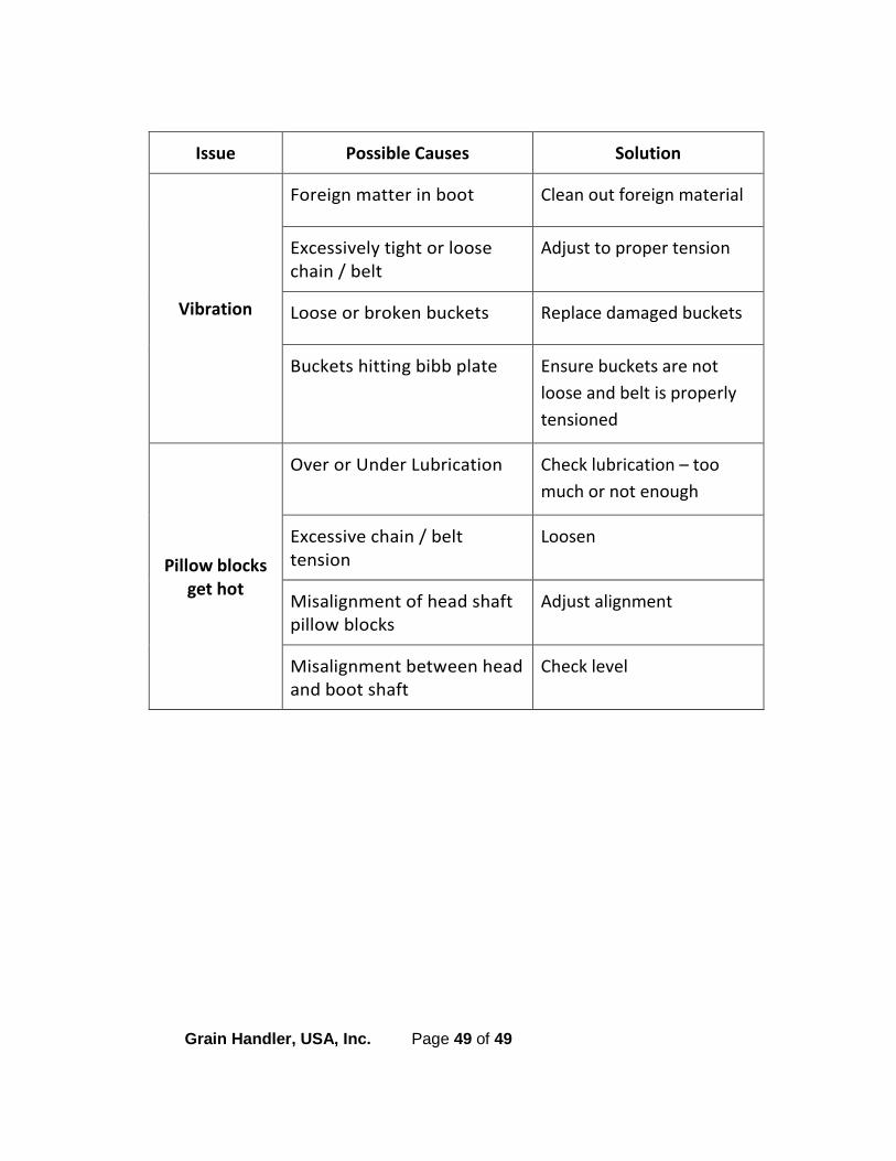
Issue Possible Causes Solution
Vibration
Foreign matter in boot Clean out foreign material
Excessively tight or loose chain / belt
Adjust to proper tension
Loose or broken buckets Replace damaged buckets
Buckets hitting bibb plate Ensure buckets are not loose and belt is properly tensioned
Pillow blocks get hot
Over or Under Lubrication Check lubrication – too much or not enough
Excessive chain / belt tension
Loosen
Misalignment of head shaft pillow blocks
Adjust alignment
Misalignment between head and boot shaft
Check level