COMMITTEE DRAFT OIML/ 2 CD Date: November 2013 OIML TC 9 ... · COMMITTEE DRAFT OIML/ 2 CD Date:...
95
COMMITTEE DRAFT OIML/ 2 CD Date: November 2013 Reference number: OIML TC 9/SC 2/R 61-1 2 CD Supersedes document: OIML R61-1 Automatic gravimetric filling Instruments Editon 2004 (E) TITLE OF THE CD (English): OIML R61 Automatic gravimetric filling Instruments Part 1: Metrological and technical requirements Part 2: Metrological controls and performance tests TITLE OF THE CD (French): OIML R 61 Doseuses pondérales à fonctionnement automatique Partie 1: Exigences métrologiques et techniques Partie 2: Contrôles métrologiques et essais de performance Original version in: English: OIML R 61-1 Edition 2004 (E)
Transcript of COMMITTEE DRAFT OIML/ 2 CD Date: November 2013 OIML TC 9 ... · COMMITTEE DRAFT OIML/ 2 CD Date:...
COMMITTEE DRAFT OIML/ 2 CD Date: November 2013 Reference number: OIML TC 9/SC 2/R 61-1 2 CD Supersedes document:
OIML R61-1 Automatic gravimetric filling Instruments Editon 2004 (E)
TITLE OF THE CD (English):
OIML R61 Automatic gravimetric filling Instruments Part 1: Metrological and technical requirements Part 2: Metrological controls and performance tests
TITLE OF THE CD (French): OIML R 61 Doseuses pondérales à fonctionnement automatique Partie 1: Exigences métrologiques et techniques Partie 2: Contrôles métrologiques et essais de performance Original version in: English: OIML R 61-1 Edition 2004 (E)

R61-1 Page 2
CONTENTS Foreword ……………………………………………………………………………………………………………….
0 Terminology (terms and definitions) ……………………..………………………………………………….. PART 1 – METROLOGICAL AND TECHNICAL REQUIREMENTS 1 Introduction 6 2 Scope 6 3 Units of measurements 16 4 Metrological requirements ………………………………………………………………………..
4.1 Accuracy classes 4.2 Error limitation 4.3 Particle mass correction 4.4 Maximum permissible preset value error (setting error) MPSE 4.5 Minimum capacity (Min) 4.6 Rated Minimum fill (Minfill) 4.7 Influence factors 5 Technical requirements ………………………………………………………………………………
5.1 Suitability for use 5.2 Security of operation 5.3 Indication of weighing results 5.4 Fill setting device 5.5 Final feed cut-off device 5.6 Feeding device 5.7 Load receptor 5.8 Zero-setting and tare devices 5.9 Data Storage 5.10 Software 5.11 Equilibrium mechanism 5.12 Descriptive markings 5.13 Verification marks 6 Control instrument 7 Requirements for electronic instruments ………………………………………………………. 22
7.1 General requirements 7.2 Functional requirements 7.3 Examination and tests PART 2 – METROLOGICAL CONTROLS AND PERFORMANCE TESTS 8 Metrological controls ……………………………………………………………………………... 25
8.1 General 8.2 Type approval 8.3 Initial verification 8.4 Subsequent verification 8.5 In-service inspection 9 Test methods …………………………………………………………………………………………… 29
9.1 Determination of the mass of individual fills 9.2 Conduct of material tests 9.3 Number of fills 9.4 Accuracy of standards 9.5 Material test methods 9.6 Preset value 9.7 Mass and average value of the test fill 9.8 Deviation for automatic weighing 9.9 Preset value error for automatic weighing ANNEX A TESTING PROCEDURES FOR AUTOMATIC GRAVIMETRIC FILLING INSTRUMENTS 33
A.1 Administrative examination A.2 Examination for initial verification A.3 General test requirements A.4 Test program A.5 Static tests
A.6 Influence factor tests and disturbance tests……………………… …………………56
A.6.2.1 Temperature with static load A.6.2.2 Temperature effect on no-load indication A.6.2.3 Damp heat, steady state A.6.2.4 AC mains voltage variation A.6.2.5 DC mains voltage variation
R61-1 Page 3
A.6.2.6 Battery voltage variation (DC), not connected to mains A.6.2.7 Power from external 12V and 24V road vehicle batteries A.6.2.8 Tilting A.6.3.1 AC mains voltage dips, short interruptions and reductions A.6.3.2 Bursts (fast transient tests) on mains power lines and on signal, data and control lines A.6.3.3 Electrostatic discharge A.6.3.4 Immunity to electromagnetic fields A.6.3.5 Surges on AC and DC mains power lines and on signal, data and control lines A.7 Span stability test A.8 Procedure for material tests Annex B Additional examinations and tests for software-controlled digital devices and
instruments Annex C Equipment Under Test Bibliography……………………………………………………………………………………………………..59
R61-1 Page 4
EXPLANATORY NOTE
OIML TC 9/SC 2 Automatic weighing instruments
Secretariat: United Kingdom (National Measurement Office)
BIML Contact
Mr. Ian Dunmill
P-Members (25)
AUSTRALIA AUSTRIA BELGIUM
CROTIA CUBA CZECH REPUBLIC
DENMARK FINLAND FRANCE
GERMANY INDIA JAPAN
KOREA (R.) NETHERLANDS NORWAY
POLAND P.R. CHINA POLAND
ROMANIA RUSSIAN FEDERATION SLOVENIA
SOUTH AFRICA SPAIN SWEDEN
SWITZERLAND TURKEY UNITED KINGDOM
UNITED STATES
O-Members (13) ARGENTINA BRAZIL BULGARIA
CANADA HUNGARY INDONESIA
IRAN IRELAND LIBERIA
SAUDI ARABIA SERBIA SLOVAKIA
UNITED ARAB EMIRATES
Liaisons
CECIP, European Committee of Weighing Instruments Manufacturers
COPAMA, Confederation of Packaging Machinery Associations
ISO, International Standardization Organization

R61-1 Page 5
FOREWORD
The International Organization of Legal Metrology (OIML) is a worldwide, intergovernmental organization whose primary aim is to harmonize the regulations and metrological controls applied by the national metrological services, or related organizations, of its Member States. The main categories of OIML publications are:
International Recommendations (OIML R), which are model regulations that establish the metrological characteristics required of certain measuring instruments and which specify methods and equipment for checking their conformity. OIML Member States shall implement these Recommendations to the greatest possible extent;
International Documents (OIML D), which are informative in nature and which are intended to harmonize and improve work in the field of legal metrology;
International Guides (OIML G), which are also informative in nature and which are intended to give guidelines for the application of certain requirements to legal metrology; and
International Basic Publications (OIML B), which define the operating rules of the various OIML structures and systems. OIML Draft Recommendations, Documents and Guides are developed by Technical Committees or Subcommittees which comprise representatives from the Member States. Certain international and regional institutions also participate on a consultation basis. Cooperative agreements have been established between the OIML and certain institutions, such as ISO and the IEC, with the objective of avoiding contradictory requirements. Consequently, manufacturers and users of measuring instruments, test laboratories, etc. may simultaneously apply OIML publications and those of other institutions.
International Recommendations, Documents, Guides and Basic Publications are published in English (E) and translated into French (F) and are subject to periodic revision.
Additionally, the OIML publishes or participates in the publication of Vocabularies (OIML V) and periodically commissions legal metrology experts to write Expert Reports (OIML E). Expert Reports are intended to provide information and advice, and are written solely from the viewpoint of their author, without the involvement of a Technical Committee or Subcommittee, nor that of the International Committee of Legal Metrology. Thus, they do not necessarily represent the views of the OIML.
This publication - reference OIML R 61-1, Edition XXX - was developed by Technical Subcommittee TC 9/SC 2 Automatic weighing instruments. It was approved for final publication by the International Committee of Legal Metrology in XXX and will be submitted to the International Conference of Legal Metrology in XXX for formal sanction. It supersedes the previous edition of R 61-1 (2004).
OIML Publications may be downloaded from the OIML web site in the form of PDF files. Additional information on OIML Publications may be obtained from the Organization’s headquarters:
Bureau International de Métrologie Légale 11, rue Turgot - 75009 Paris - France
Telephone: 33 (0)1 48 78 12 82 Fax: 33 (0)1 42 82 17 27 E-mail: [email protected] Internet: www.oiml.org

R61-1 Page 6
*
* *

R61-1 Page 7
0 TERMINOLOGY (terms and definitions) The terminology used in this Recommendation conforms to the International Vocabulary of Basic and General Terms in Metrology (VIM) [1], the International Vocabulary of Legal Metrology (VIML) [2], the OIML B 3 Basic Certificate System for OIML Type Evaluation of Measuring Instruments [3], the OIML D 11 General requirements for Electronic
Measuring Instruments [4], the OIML R 76 Non-automatic weighing instruments [7], and to the OIML D 31 General requirements for software controlled measuring instruments [23]. In addition, for the purposes of this Recommendation, the following definitions apply.
0.1 general definitions
0.1.1 mass
physical quantity, which can be ascribed to any material object and which gives a measure of its quantity of matter OIML D 28, 2 [25] 0.1.1.1 particle mass particle mass is a small localized object to which can be ascribed physical or chemical properties such as volume or mass.
0.1.2 load (L)
amount of material (or object) that can be carried at any one time by specified means
0.1.3 fill (F)
one load, or more loads combined, that make up the predetermined mass.
0.1.4 weight quantity representing the force resulting from the effect of gravity on a load.
0.1.5 weighing
process of determining the mass of a load using the effect of gravity on that load. 0.1.6 weighing instrument
measuring instrument used to determine the mass of a body by using the action of gravity on the body.
NOTE: In this Recommendation “mass” (or “weight value”) is preferably used in the sense of “conventional mass” or “conventional value of the result of weighing in air” according to OIML R 111 [5] and OIML D 28 [25], whereas “weight” is preferably used for an embodiment (= material measure) of mass that is regulated in regard to its physical and metrological characteristics.
According to its method of operation, a weighing instrument is classified as an automatic or non-automatic instrument. 0.1.7 measurement result
result of measurement
R61-1 Page 8
set of quantity values being attributed to a meas-urand together with any other available relevant information 0.1.8 metrologically relevant device any device, module, part, component or function of a weighing instrument that may influence the weighing result or any other primary indication is considered as metrologically relevant.
0.1.9 audit trail continuous data file containing a time stamped information record of events, e.g. changes in the values of the parameters of a device or software updates, or other activities that are legally relevant and which may influence the metrological characteristics. OIML D 31, 3.1.2 [23] 0.2 categories of instruments 0.2.1 automatic weighing instrument
weighing instrument operating without the intervention of an operator and /or follows a predetermined program of automatic process characteristic of the instrument. 0.2.2 automatic gravimetric filling instrument (AGFI)
automatic weighing instrument intended to fill containers with a predetermined and virtually constant mass of product from bulk (including liquid material) by automatic weighing, and which comprises essentially automatic feeding device(s)associated with weighing module(s) and the appropriate control and discharge devices. 0.2.2.1 associative (selective combination) weigher
AGFI comprising one or more weighing modules and which computes an appropriate combination of the loads and combines them to a fill. 0.2.2.2 cumulative weigher
AGFI comprising one weighing module with the facility to apply more than one weighing cycle for the composition of the desired fill. 0.2.2.3 subtractive weigher
AGFI for which the fill is determined by controlling the output feed from the weigh hopper.
0.2.2.4 control instrument
weighing instrument used to determine the mass of the test fill(s) delivered by the AGFI. The control instrument used during testing may be:
a) separate, from the instrument being tested

R61-1 Page 9
b) integral, the instrument being tested is used as the control instrument
0.3 construction NOTE: In this Recommendation the term “device” is applied to any part of the AGFI
which uses any means to perform one or more specific functions irrespective of the physical realisation e.g. by a mechanism or a key initiating an operation; the device may be a small part or a major portion of theAGFI.
0.3.1 principal parts 0.3.1.1 weighing module
device which provides information on the mass of the load to be measured. This device may consist of all or part of a non-automatic weighing instrument. 0.3.1.2 load receptor
part of the instrument intended to receive the load. 0.3.1.3 feeding device
device which provides a supply of product from bulk to the weighing module. It may operate in one or more stages. 0.3.1.4 control device
device that control the operation of the feeding process. The devices may incorporate software functions. 0.3.1.4.1 feed control device
device which regulates the rate of feed of the feeding device. 0.3.1.4.2 fill setting device
device which allows the setting of the preset value of the fill. 0.3.1.4.3 final feed cut-off device device which controls the cut-off of the final feed so that the average mass of the fills corresponds to the preset value. This device may include an adjustable compensation for the material in flight. 0.3.1.4.4 correction device device which automatically corrects the setting of the AGFI. 0.3.2 electronic parts
0.3.2.1 electronic instrument
instrument equipped with electronic devices

R61-1 Page 10
0.3.2.2 electronic device
device employing electronic sub-assemblies and performing a specific function. Electronic devices are usually manufactured as separate units and are capable of being independently tested. OIML D 11, 3.2 [4]
NOTE 1: An electronic device may be a complete measuring instrument (for example: counter scale) or a part of a measuring instrument (for example: printer, indicator).
NOTE 2: An electronic device can be a module in the sense that this term is used in
OIML Publication B 3 “The OIML Certificate System for Measuring Instruments” [3].
0.3.3 indicating device (of a weighing instrument)
part of the load measuring device that displays the value of a weighing result in units of mass and may additionally display: the difference between mass of a load and a reference value
the value of the fill(s) and /or related quantities or parameters of a number of consecutive weighings.
0.3.4 zero-setting device
device for setting the indication to zero when there is no load on the load receptor. OIML R76, T.2.7.2 [7] 0.3.4.1 non-automatic zero-setting device
device for setting the indication to zero by an operator. OIML R76, T.2.7.2.1 [7] 0.3.4.2 semi-automatic zero-setting device
device for setting the indication to zero automatically following a manual command. OIML R76, T.2.7.2.2 [7] 0.3.4.3 automatic zero-setting device
device for setting the indication to zero automatically without the intervention of an operator. OIML R76, T.2.7.2.3 [7] 0.3.4.4 initial zero-setting device
device for setting the indication to zero automatically at the time the instrument is switched on and before it is ready for use. OIML R76, T.2.7.2.4 [7].
R61-1 Page 11
0.3.4.5 zero-tracking device device for maintaining the zero indication within certain limits automatically. OIML R76, T.2.7.3 [7] 0.3.5 tare device
device for setting the indication to zero when a load is on the load receptor::
a) without altering the weighing range for net loads (additive tare device), or b) reducing the weighing range for net loads (subtractive tare device).
The tare device may function as:
a) a non-automatic device (load balanced by operator), b) a semi-automatic device (load balanced automatically following a single manual
command), c) an automatic device (load balanced automatically without the intervention of an
operator). OIML R76, T.2.7.4 [7]
0.3.6 software
0.3.6.1 legally relevant software
part of the applied software that is subject to legal control. VIML, 6.10 [2]
0.3.6.2 legally relevant parameter
parameter of a measuring instrument (electronic) device, sub-assembly, software or a module subject to legal control. NOTE: The following types of legally relevant parameters can be distinguished: type-
specific parameters and device-specific parameters. VIML, 4.10 [2]
0.3.6.3 type-specific parameter
legally relevant parameter with a value that depends on the type of instrument only. VIML 4.11, [2] NOTE: Type-specific parameters are part of the legally relevant software.
Examples of type-specific parameters are: parameters used for weight value calculation, stability analysis or price calculation and rounding, software identification.
0.3.6.4 device-specific parameter legally relevant parameter with a value that depends on the individual instrument. VIML 4.12, [2]
0.3.6.5 software identification

R61-1 Page 12
sequence of readable characters (e.g. version number, checksum) that is inextricably linked to the software or software module under consideration. It can be checked on an instrument while in use. VIML, 6.01 [2]
0.3.6.6 software separation
separation of the software in measuring instruments which can be divided into a legally relevant part and a legally non-relevant part. VIML, 6.02 [2]
0.3.7 data storage device
storage device used for keeping weighing data ready after completion of the measurement for subsequent indication, data transfer, totalizing, etc. 0.3.8 interface shared boundary between two functional units, defined by various characteristics pertainingto the functions, physical interconnections, signal exchanges, and other characteristicsof the units, as appropriate. OIML D 31, 3.1.27 [23] 0.3.9 user interface interface that enables information to be interchanged between the operator and the measuring instrument or its hardware or software components, e.g. switches, keyboard, mouse, display, monitor, printer, touch-screen, software window on a screen including the software that generates it. VIML 6.15 [2] Note: Often also designated as “HMI” (human machine interface) 0.3.10 protective interface interface (hardware and/or software) which will only allow the introduction into the instrument of data or instructions that cannot influence the metrological properties of the instrument. 0.3.11 module identifiable part of an instrument or device that performs a specific function or functions, and that can be separately evaluated according to the metrological and technical performance requirements in this Recommendation. OIML B 3, 3.4 [3] NOTE: The modules of the AGFI may be subject to specified partial error limits. Typical modules of the AGFI are: load cell, indicator, analogue or digital
processors, weighing module, remote display, software.
Figure 1
Definition of typical modules according to 0.2.11 and 5.1.6

R61-1 Page 13
(other combinations are possible)
load cell (0.3.11.1) 2 + 3 + (4)*)
indicator (0.3.11.2) (3) + 4 + (5) + (6) + 7
analogue data processing device
(0.3.11.3) 3 + 4 + (5) + (6)
digital data processing device
(0.3.11.4) (4) + 5 + (6)
primary display (0.3.11.5) 7
weighing module (0.3.11.6) 1 + 2 + 3 + 4 + (5) + (6)
Terminal (0.3.11.7) (5) + 6 + 7
*
) Numbers in brackets indicate options
0.3.11.1 load cell
measuring transducer that, in response to an applied load will produce an output. This output may be converted by another device into measurement units such as mass. . OIML R 60 [7]
0.3.11.1.1 load cell equipped with electronics

R61-1 Page 14
load cell employing an assembly of electronic components having a recognizable function of its own. Note: Load cells equipped with electronics that produce an output in digital form are
often referred to as “digital load cells” (see Figure 1). OIML R 60 [7] . 0.3.11.2 indicator electronic device that may perform the analogue-to-digital conversion of the output signal of the load cell, and further process the data, and display the weighing results. 0.3.11.3 analogue data processing device electronic device that performs the analogue-to-digital conversion of the output signal of the load cell, and further processes the data, and supplies the weighing result in a digital format via a digital interface without displaying it. 0.3.11.4 digital data processing device electronic device that processes digital data. 0.3.11.5 primary display digital display, either incorporated in the indicator housing, or in the terminal housing or realized as a display in a separate housing (i.e. terminal without keys), e.g. for use in combination with a weighing module. 0.3.11.6 weighing module part providing information on the mass of the load to be measured. It may optionally have devices for further processing (digital) data and operating the AGFI.
0.3.11.7 terminal
digital device equipped with operator interface(s) such as a keypad, mouse, touch-screen, etc. used to monitor the operations of the instrument. Also equipped with a display to provide feedback to the operator, such as: weighing results; belt speed; flow rate; etc. transmitted via the digital interface of a weighing module or an analogue data processing device.
0.4 metrological characteristics 0.4.1 scale interval (d) value, expressed in units of the measured quantity of the difference between:
a) the values corresponding to two consecutive scale marks for analogue indication, or
b) two consecutive indicated values for digital indication. VIML, 5.01 [2]

R61-1 Page 15
0.4.2 reference particle mass of a product
mass equal to the mean of ten of the largest particles or pieces of the product taken from one or more fills. 0.4.3 preset value
value, expressed in units of mass, preset by the operator by means of the fill setting device, in order to define the nominal value of the fills. 0.4.4 static set point
value of the test weights or masses which, in static tests, balance the value selected on the indication of the fill setting device. 0.4.5 weighing cycle
the combination of operations including:
a) delivery of material to the load receptor, b) a weighing operation, and c) the discharge of a single discrete load
after the completion of which the AGFI is in its initial state. 0.4.6 final feed time
time taken to complete the last stage of delivery of the product to a load receptor. 0.4.7 minimum capacity (Min) smallest discrete load that can be weighed automatically on a load receptor of the AGFI. NOTE: For AGFIs which effect the fill by one weighing cycle minimum capacity (Min) is
equal to the rated minimum fill (Minfill). 0.4.8 maximum capacity (Max) largest discrete load that can be weighed automatically on a load receptor of the AGFI. 0.4.9 rated minimum fill (Minfill)
rated value of the fill below which the weighing results may be subject to errors outside the limits specified in this Recommendation.
NOTE: For AGFIs which effect the fill by more than one weighing cycle Minfill is larger
than the minimum capacity (Min).
0.4.10 average number of loads per fill half the sum of the maximum and minimum number of loads per fill that can be set by the operator or, in cases where the number of loads per fill is not directly determined by the operator, either the mean of the actual number of loads per fill (if known) in a period of normal operation, or the optimum number of loads per fill as may be specified by the manufacturer for the type of product which is to be weighed.
R61-1 Page 16
0.4.11 static test load
load that is used in static tests only. 0.4.12 minimum discharge
smallest load that can be discharged from a subtractive weigher. 0.4.13 warm-up time
time between the moment power is applied to an instrument and the moment at which the instrument is capable of complying with the requirements. 0.5 indications and errors 0.5.1 indication of a measuring instrument quantity value provided by a measuring instrument or measuring system VIM, 4.1 [1]. Note: “Indication”, “indicate” or “indicating” includes both displaying, and/or printing. 0.5.1.1 primary indications values of fills, signals and symbols that are subject to the requirements of this Recommendation. 0.5.1.2 secondary indications indications, signals and symbols that are not primary indications. 0.5.1.3 analogue indication
indication allowing the evaluation of an equilibrium position to a fraction of the scale interval. 0.5.1.4 digital indication
indication in which the scale marks comprise a sequence of aligned figures that do not permit interpolation to fractions of a scale interval. 0.5.1.5 digital display digital display (device) is an output device visualizing actual information in volatile digital format.
NOTES: a) A digital display may concern a primary display or a secondary display.
b) The terms “primary display” and “secondary display” should not be confused
with the terms “primary indication” and “secondary indication” (0.4.1.1 and 0.4.1.2).

R61-1 Page 17
0.5.1.6 secondary display
additional (optional) digital peripheral device, which repeats the weighing result and any other primary indication, or provides further, non-metrological information.
0.5.2 error 0.5.2.1 measurement error
error of measurement error
measured quantity value minus a reference quantity value. VIM 2.16 [1] NOTE 1: The concept of ‘measurement error’ can be used both:
a) when there is a single reference quantity value to refer to, which occurs if a calibration is made by means of a measurement standard with a measured quantity value having a negligible measurement uncertainty or if a conventional quantity value is given, in which case the measurement error is known, and
b) if a measurand is supposed to be represented by a unique true quantity value or a set of true quantity values of negligible range, in which case the measurement error is not known.
NOTE 2: Measurement error should not be confused with production error or mistake. 0.5.2.2 intrinsic error
error of a measuring instrument, determined under reference conditions. VIML, 0.06 [2] 0.5.2.3 initial intrinsic error
intrinsic error of a measuring instrument as determined prior to performance tests and durability evaluations VIML 5.10 [2]
0.5.2.4 maximum permissible measurement error (MPME) maximum permissible error (MPE)
extreme value of measurement error, with respect to a known reference quantity value, permitted by specifications or regulations for a given measurement, measuring instrument, or measuring system NOTE 1: usually, the term “maximum permissible errors” or “limits of error” is used where
there are two extreme values. NOTE 2: the term “tolerance” should not be used to designate ‘maximum permissible
error’. VIM 4.26 [1] 0.5.2.4.1 maximum permissible deviation of each fill (MPD) maximum permissible deviation of each fill from the average value of all the fills of a test sequence. 0.5.2.4.2 maximum permissible preset value error (MPSE)

R61-1 Page 18
maximum permissible setting error for each preset value of the fill.
0.5.2.4.3 maximum permissible error for influence factor tests
maximum permissible error for weighing results during influence factor tests.
0.5.2.5 fault
difference between the error of indication and instrinsic error of a measuring instrument. OIML D11, 3.9 [4] NOTE 1: Principally, a fault is the result of an undesired change of data contained in
or flowing through an electronic instrument.
NOTE 2: From the definition it follows that a “fault” is a numerical value which is expressed either in a unit of measurement or as a relative value, for instance as a percentage.
0.5.2.6 significant fault
fault greater than 0.25 MPD NOTE: For each fill, the value of 0.25 MPD is that appropriate to each fill for in-service inspection (see4.2.1), equal to the minimum capacity or rated minimum fill.
the following are not considered to be significant faults, even when they exceed the value defined above:
a) faults arising from simultaneous and mutually independent causes in the AGFI, b) faults that imply it is impossibile to perform a measurement c) faults that are so serious that they will inevitably be noticed by those interested in the
measurement, d) transitory faults that are momentary variations in the indications or operation that can
not be interpreted, memorized or transmitted as a measurement result.
NOTE: For AGFIs where the fill may be greater than one load, the value of the significant fault applicable for a test on a static load shall be calculated in accordance with the test procedures in A.6.1.3. Adapted from OIML D11, 3.12 [4]
0.5.2.7 span stability
capability of an instrument to maintain the difference between the indication at maximum capacity and the indication at zero over a period of use within specified limits. 0.5.3 reference value for accuracy class (Ref(x))
value for accuracy class determined by static testing of the weighing module during influence quantity testing at type evaluation stage. Ref(x) is equal to the best accuracy class for which the AGFI may be verified for operational use.

R61-1 Page 19
0.6 influences and reference conditions 0.6.1 influence quantity quantity that, in a direct measurement, does not affect the quantity that is actually measured, but affects the relation between the indication and the measurement result VIM 2.52 [1] 0.6.1.1 influence factor
influence quantity having a value within the rated operating conditions of a measuring instrument specified in this recommendation. VIML, 5.15 [2] 0.6.1.2 disturbance
influence quantity having a value within the limits specified in this Recommendation but outside the rated operating conditions of the measuring instrument. VIML, 5.16 [2] 0.6.2 rated operating conditions
operating condition that must be fulfilled during measurement in order that a measuring instrument or measuring system perform as designed. VIM, 4.9 [1] NOTE: Rated operating conditions generally specify intervals of values for a quantity
being measured and for any influence quantity.
0.6.3 reference conditions
operating condition prescribed for evaluating the performance of a measuring instrument or measuring system or for comparison of measurement results. VIM 4.11 [1] NOTE 1: Reference operating conditions specify intervals of values of the
measurand and of the influence quantities. NOTE 2: In IEC 60050-300, item 311-06-02, the term “reference condition” refers to
an operating condition under which the specified instrumental measurement uncertainty is the smallest possible.
0.7 tests 0.7.1 material test
test carried out on a complete AGFI using the type of material which it is intended to weigh. 0.7.2 simulation test
test carried out on a complete AGFI or part of the AGFI in which any part of the weighing operation is simulated. 0.7.3 performance test
test to verify whether the equipment under test (EUT) is able to accomplish its intended functions. VIML, 5.18 [2]

R61-1 Page 20
0.7.4 span stability test
test to verify that the EUT is capable of maintaining its span stability.
0.8 Abbreviations and Symbols
- I = Indication - In = nth indication - L = Load - ΔL = Additional load to next changeover point - P = I + ½ d – ΔL = Indication prior to rounding (digital indication) - E = I – L or P – L = Error - F = Mass of fill - FP = Preset value of fill - Pi = Fraction of the MPE(1) applicable to one part of the instrument which is
examined separately - (x) = Class designation factor - MPE = Maximum permissible error (absolute value) - EUT = Equipment under test - MPE(1) = Maximum permissible error for influence factor tests for class X(1) - se = Preset value error (setting error) - MPSE(1) = Maximum permissible preset value error for class X(1) - mdmax = Maximum of the actual deviations of each fill from the average of all fills - MPD(1) = Maximum permissible deviation of each fill from the average for class X(1) - mpΔz(1) = Maximum permissible zero change per 5 °C for class X(1) - AGFI = Automatic gravimetric filling instrument
PART 1 – METROLOGICAL AND TECHNICAL REQUIREMENTS
1 Introduction This OIML Recommendation consists of 3 parts: Part 1: Metrological and Technical Requirements; Part 2: Metrological Controls and Performance Tests; Part 3: Report Format for Type Evaluation. Parts 1 and 2 are a combined publication and Part 3 is a separate publication
2 Scope This International Recommendation specifies the metrological and technical requirements, metrological controls and tests for automatic gravimetric filling instruments (hereafter referred to as “AGFI(s)”) which produce predetermined mass of individual fills of products from one or more loads by automatic weighing.
R61-1 Page 21
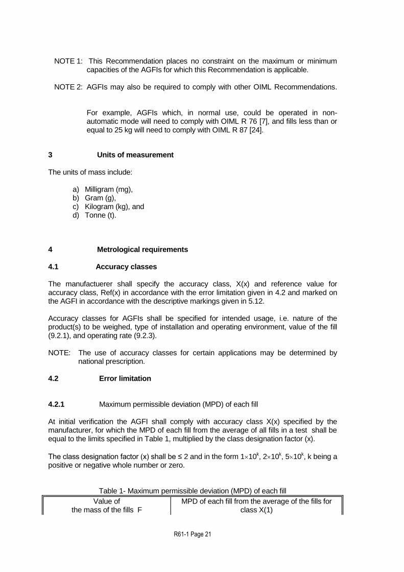
NOTE 1: This Recommendation places no constraint on the maximum or minimum
capacities of the AGFIs for which this Recommendation is applicable. NOTE 2: AGFIs may also be required to comply with other OIML Recommendations.
For example, AGFIs which, in normal use, could be operated in non-automatic mode will need to comply with OIML R 76 [7], and fills less than or equal to 25 kg will need to comply with OIML R 87 [24].
3 Units of measurement The units of mass include:
a) Milligram (mg), b) Gram (g), c) Kilogram (kg), and d) Tonne (t).
4 Metrological requirements 4.1 Accuracy classes The manufactuerer shall specify the accuracy class, X(x) and reference value for accuracy class, Ref(x) in accordance with the error limitation given in 4.2 and marked on the AGFI in accordance with the descriptive markings given in 5.12. Accuracy classes for AGFIs shall be specified for intended usage, i.e. nature of the product(s) to be weighed, type of installation and operating environment, value of the fill (9.2.1), and operating rate (9.2.3). NOTE: The use of accuracy classes for certain applications may be determined by
national prescription. 4.2 Error limitation
4.2.1 Maximum permissible deviation (MPD) of each fill
At initial verification the AGFI shall comply with accuracy class X(x) specified by the manufacturer, for which the MPD of each fill from the average of all fills in a test shall be equal to the limits specified in Table 1, multiplied by the class designation factor (x).
The class designation factor (x) shall be ≤ 2 and in the form 1 10k, 2 10k, 5 10k, k being a positive or negative whole number or zero.
Table 1- Maximum permissible deviation (MPD) of each fill
Value of the mass of the fills F
MPD of each fill from the average of the fills for class X(1)

R61-1 Page 22
(as percentage of F or in grams)
(g) Initial verification In-service inspection
50 <
100 < 200 < 300 < 500 < 1000 < 10000 < 15000 <
F F F F F F F F F
50
100
200
300
500
1000
10000
15000
7.2 % 3.6 g 3.6 % 7.2 g 2.4 % 12 g
1.2 % 120 g 0.8 %
9 % 4.5 g 4.5 %
9 g 3 % 15 g
1.5 % 150 g 1 %
(See 9.3 for the number of fills required to find the average value). 4.2.2 Maximum permissible error (MPE) for static loads The AGFI shall have a reference value for accuracy class, Ref(x), applicable for static testing at type evaluation stage, for which the MPE for influence factor tests shall be 0.25 of the MPD for in-service inspection for a fill equal to the static test load.
NOTE: For AGFIs where the fill may not be equal to one load, the MPE applicable for a
test on a static load shall be calculated in accordance with the test procedures in A.6.
4.2.3 Maximum permissible preset value error (MPSE) For AGFIs where it is possible to preset the maximum difference between the preset value (as defined in 5.6) and the average mass of all the fills in a test sequence (as defined in 9.7) shall not exceed 0.25 of the MPD of each fill from the average of the fills, as specified for in-service inspection in 4.2.1. These limits will apply for Initial verification and in-service inspection tests.
4.3 Particle mass correction (see 0.4.2)
For material tests, when the reference particle mass exceeds 0.1 of the maximum MPD in-service, the values derived from Table 1 shall be increased by 1.5 times the value of the reference particle mass. However, the maximum value of the MPD shall not exceed the value derived from Table 1 multiplied by 9 %. NOTE 1: Particle mass correction is not applicable to limits which are derived from Table
1, e.g. influence quantity tests, zero setting etc. NOTE 2: AGFIs which are verified with particle mass correction may not be suitable for
fills which need to comply with OIML R87 [24]. 4.4 Error limits for mutli-load AGFIs The effect on the fill shall not be greater than the significant fault value specified in 0.5.2.6 and the MPE specified in 4.2.2.

R61-1 Page 23
4.5 Minimum capacity (Min) The Min is the smallest load value specified by the manufacturer which can be automatically weighed on a load receptor within the error limits and requirements for AGFIs given in this Recommedation. The Min shall be marked on the AGFI in accordance with the descriptive markings in 5.12.
NOTE: For AGFIs which effect the fill by one weighing cycle Min is equal to the Minfill.
4.6 Rated Minimum Fill (Minfill) The Minfill shall be specified by the manufacturer. The MPE is applicable to each fill >= Minfill Note: At least the following parameters are of influence to the value of the Minfill
Temperature effect on no load indication
Zero-setting accuracy
Disturbances
Warm-up time
For class X(x) AGFIs the minimum permissible values of Minfill for d values are given in Table 2 below:
Table 2 Minimum permissible value of Minfill (g)
d (g)
X(0.2) X(0.5) X(1) X(2)
0.5 28 11 6 3
1 111 22 11 6
2 334 44 22 12
5 1665 335 110 30
10 3330 1330 330 110
20 6660 2660 1340 340
50 25000 6650 3350 1650
100 50000 20000 6700 3300
200 100000 40000 20000 6600
500 500 d 200 d 100d 50 d
Notes:
a) These values are dependent on the products, conditions of use and whether operational tests have demonstrated that the tolerances have been met for this value
b) The gramme values are rounded to the d values which can be
indicated
With a resolution in scale interval (d) and the equilibrium device the AGFI is able to meet the requirement of 5.8.2 with an error E = 0.25d, only if the test results show that the scale interval (d) is the largest contribution to the calculation of the Minfill the table
is as presented. Since 5.8.2 require that 0.25d 0.25 MPD in-service * Minfill, then you
have the condition: Minfill d / MPD in-service (with MPD as relative value).

R61-1 Page 24
For calculating the Minfill value for class X(x) AGFIs the MPD and F values (value of the mass of the fills) in Table 1 are used. See Annex E for examples.
4.7 Influence factors
The permissible effects of influence factors on AGFIs under simulated conditions are specified for each case below. Refer to Annex A for test conditions. AGFIs shall maintain their metrological and technical characteristics at a relative humidity of either 85 % (non condensing) or 93 % (condensing) (see A.6.2.3) at the upper limit of the temperature range of the belt weigher.
4.7.1 Temperature
4.7.1.1 Prescribed temperature limits If no particular working temperature is stated in the descriptive markings of the AGFI, then the AGFI shall comply with the appropriate metrological and technical requirements at temperatures from:
-10 C to + 40 C The temperature limits shall be marked on the AGFI in accordance with the descriptive markings in 5.12.
4.7.1.2 Special temperature limits
For special applications the limits of the temperature range may differ from those given
above but such a range shall not be less than 30 C and shall be specified in the descriptive markings.
4.7.1.3 Temperature effect on no load indication
At specified temperatures the indication at zero shall not vary by more than the MPE for influence factor tests specified in 4.2.2 for a load equal to the Minfill for a difference in
ambient temperature of 5 C.
4.7.2 Supply voltage
An electronic instrument shall comply with the appropriate metrological and technical requirements, if the supply voltage varies from the nominal voltage, Unom (if only one voltage is marked on the AGFI), or from the voltage range, Umin (lowest value), Umax
(highest value), marked on the AGFI at:
a) AC mains voltage variation: 1) lower limit = 0.85 Unom or 0.85 Umin 2) upper limit = 1.10 Unom or 1.10 Umax

R61-1 Page 25
b) DC mains voltage variation: 1) The upper voltage limit is the DC level at which the EUT has been
manufactured to automatically detect high-level conditions. 2) The lower limit will be the DC level at which the EUT has been manufactured
to automatically detect low-level conditions. c) Low voltage of internal battery (not connected to the mains power)
The lower limit will be the minimum operating voltage specified by the manufacturer
d) Power from external 12V and 24 V road vehicle batteries The upper and lower limit are the specified maximum and minimum power supply voltage.
4.7.3 Tilting Mobile AGFIs intended to be used outside in open locations (e.g. on roads) or AGFIs
liable to be tilted and which does not have a level indicator shall comply with the appropriate metrological and technical requirements when tilted (longitudinally and transversely) by up to 5 %.
a) Where a levelling device and a level indicator is present the limiting value of tilting shall be defined by a marking (e.g. for an air bubble level indicator: a ring on the level indicator which shows that the maximum permissible tilt has been exceeded when the bubble is displaced from a central position and the edge touches the marking). The limiting value of the level indicator shall be obvious, so that tilting is easily noticed. The level indicator shall be fixed firmly on the AGFI in a place clearly visible to the user and representative for the tilt sensitive part.
b) If the AGFI is fitted with an automatic tilt sensor the limiting value of tilting is
defined by the manufacturer. The tilt sensor shall release a display switch-off or other appropriate alarm signal (e.g. error signal) and shall inhibit the printout and data transmission if the limiting value of tilting has been exceeded
c) Where an automatic tilt sensor is also used to compensate the effect of tilting by adding a correction to the weighing result, this sensor is regarded as an essential part of the AGFI that shall be submitted to influence factors and disturbance tests during the type approval procedure.
5 Technical requirements 5.1 Suitability for use AGFIs shall be designed to suit the method of operation and the products for which it is intended. It shall be of adequately robust construction so that it maintain it metrological characteristics when properly installed and used in an environment for which it is intended. 5.2 Security of operation
5.2.1 Fraudulent use

R61-1 Page 26
AGFIs shall have no characteristics likely to facilitate its fraudulent use. 5.2.2 Accidental maladjustment AGFIs shall be so constructed that an accidental breakdown or a maladjustment of control elements likely to disturb its correct functioning cannot take place without its effect being evident.
5.2.3 Security
Means shall be provided for securing components, interfaces, software devices and pre-set controls of the AGFI, to which unauthorised access is prohibited or is detected and made evident by an audit trail or similair. National prescription may specify the security or sealing that is required.
5.3 Indication of weighing results
5.3.1 Quality of reading Reading of the results shall be reliable, bright and easy under conditions of normal use. The scales, numbering and printing shall permit the figures that form the results to be read by simple juxtaposition.
5.3.2 Form of the indication Weighing results shall contain the names or symbols of the units of mass in which they are expressed. For any one indication of weight, only one unit of mass may be used. All indicating, printing and tare weighing devices of AGFIs shall, within any one weighing range, have the same scale interval for any given load. Digital indication shall display at least one figure beginning at the extreme right.
5.3.3 Use of a printer
Printing shall be clear and permanent for the intended use. Printed figures shall be at least 2 mm high. If printing takes place, the name or the symbol of the unit of measurement shall be either to the right of the value or above a column of values. 5.3.4 Scale interval (d) Scale intervals of all indicating devices associated with a weighing module shall be the same. The scale interval for a measured value shall be in the form 1x10n, 2x10n, or 5x10n, where n is any integer or zero.

R61-1 Page 27
5.4 Fill setting device If fill setting is by means of a scale, it shall be graduated in units of mass. If fill setting is by means of weights, they shall be either weights in accordance with OIML R 111 [5] requirements or purpose-designed of any nominal value, distinguishable by shape and identified with the AGFI. 5.5 Final feed cut-off device The final feed cut-off device shall be clearly differentiated from any other device. The direction of movement corresponding to the sense of the desired result shall be shown, where applicable. For automatic mechanical scales the final feed cut-off device may include an adjustable compensation beam for the material in flight. 5.6 Feeding device The feeding device shall be designed to provide sufficient and regular flowrate(s). An adjustable feeding device shall be fitted with an indication of the direction of movement corresponding to the sense of the adjustment of the feed where applicable. 5.7 Load receptor The load receptor, and feed and discharge devices as appropriate, shall be designed to ensure that residual material retained after each discharge is negligible. AGFIs using the subtractive weighing principle shall be designed to ensure that residual material retained at feed from the discharge gate is negligible. The load receptor shall provide access and facilities so that where necessary test weights or masses up to the maximum capacity can be placed in position, in a safe and secure manner. If these facilities are not a permanent fixture of the AGFI, they must be kept in the vicinity of the AGFI. Manual discharge of the load receptor shall not be possible during automatic operation. 5.8 Zero-setting and tare devices AGFIs shall be provided with zero-setting and/or tare devices and it may be provided with additional zero tracking tracking devices. Tare devices (except preset tare devices) may also be used for zeroing. The devices may be:
a) Non-automatic (tare balancing), or b) Semi-automatic, or c) Automatic
For combined zero-setting and tare devices, the same key operates the semi-automatic zero-setting device and the semi-automatic tare device. In these cases, the accuracy requirements specified in 5.8.2 and in 5.8.4 apply at any load

R61-1 Page 28
5.8.1 Range of adjustment
The effect of any zero-setting device or any tare device shall not alter the maximum weighing capacity of the AGFI. The range of adjustment of zero-setting devices shall not exceed 4%, and of the initial zero-setting device not more than 20%, of the Max of the AGFI.
5.8.2 Accuracy of zero-setting and tare devices
Zero-setting and tare devices (except the preset tare function) shall be capable of setting to less than or equal to 0.25 d for in-service inspection as specified in 4.2.1 for a fill equal to the Min or Minfill respectively of the AGFI. After zero setting the effect of zero deviation on the result of the weighing shall be not more than ± 0.25 d.
5.8.3 Control of the zero-setting and tare devices
5.8.3.1 Non-automatic and semi-automatic devices Non-automatic or semi-automatic zero-setting and tare devices must be locked during automatic operation. The weighing module shall be in stable equilibrium when the zero-setting and tare devices are operating.
5.8.3.2 Automatic devices An automatic zero-setting device may operate at the start of automatic operation, as part of every automatic weighing cycle, or after a programmable time interval. A description of the operation of the automatic zero-setting device (e.g. the maximum programmable time interval) should be included in the type approval certificate. The automatic zero-setting device shall operate sufficiently often to ensure that zero is maintained within twice the given MPE in 5.8.2. Where the automatic zero-setting device operates as part of every automatic weighing cycle, it shall not be possible to disable this device or to set this device to operate at time intervals. Where the automatic zero-setting device operates after a programmable time interval, the manufacturer shall specify the maximum programmable time interval. The maximum programmable time interval shall not be greater than the value calculated according to the method in A.5.3.5, or shall be reduced depending on prevailing operating conditions. The maximum programmable time interval for automatic zero-setting required above and specified in A.5.3.5 may start again after taring or zero tracking has taken place. The automatic zero-setting device shall generate suitable information to draw attention to overdue zero setting.
5.8.4 Zero-tracking device

R61-1 Page 29
A zero-tracking device shall operate only when:
a) the indication is at zero, or at a negative net value equivalent to gross zero, and b) the corrections are not more than 0.25 d in-service inspection for a fill equal to
the Min or Minfill respectively of the AGFI. When zero is indicated after a tare operation, the zero-tracking device may operate within a range of 4% of Max of the AGFI around the actual zero value. NOTE: Zero-tracking is functionally similar to automatic zero setting. The
differences are important in applying the requirements of 5.8. Automatic zero-setting and zero-tracking are defined in 0.3.4.3 and 0.3.4.5. Specifically:
a) Automatic zero setting is activated by an event, such as part of every
automatic weighing cycle or after a programmed interval. b) Zero-tracking may operate continuously when the above conditions are
fulfilled and must therefore be subject to a maximum rate of correction of 0.5 MPD in-service inspection to prevent interaction with the normal weighing process.
5.8.5 Tare device 5.8.5.1 Accuracy and control of tare devices Accuracy and operation of the tare device shall be as specified in 5.8.2 and 5.8.3.
5.8.5.2 Subtractive tare device
When the use of a subtractive tare device does not allow the value of the residual weighing range to be known, a device shall prevent the use of the AGFI above its maximum capacity or indicate that this capacity has been reached.
5.8.5.3 Automatic tare device An automatic tare device may operate at the start of automatic operation, as part of every automatic weighing cycle, or after a programmable time interval. A description of the operation of the automatic tare device (e.g. the maximum programmable time interval) should be included in the type approval certificate. The automatic tare device shall operate sufficiently often to ensure that tare is properly taken into account along the production of a batch. Where the automatic zero-setting device operates as part of every automatic weighing cycle, it shall not be possible to disable this device or to set this device to operate at time intervals. Where the automatic tare device operates after a programmable time interval, the manufacturer shall specify the maximum programmable time interval.
5.8.6 Preset tare device
R61-1 Page 30
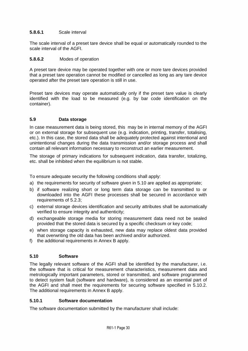
5.8.6.1 Scale interval
The scale interval of a preset tare device shall be equal or automatically rounded to the scale interval of the AGFI.
5.8.6.2 Modes of operation A preset tare device may be operated together with one or more tare devices provided that a preset tare operation cannot be modified or cancelled as long as any tare device operated after the preset tare operation is still in use.
Preset tare devices may operate automatically only if the preset tare value is clearly identified with the load to be measured (e.g. by bar code identification on the container).
5.9 Data storage
In case measurement data is being stored, this may be in internal memory of the AGFI or on external storage for subsequent use (e.g. indication, printing, transfer, totalising, etc.). In this case, the stored data shall be adequately protected against intentional and unintentional changes during the data transmission and/or storage process and shall contain all relevant information necessary to reconstruct an earlier measurement.
The storage of primary indications for subsequent indication, data transfer, totalizing, etc. shall be inhibited when the equilibrium is not stable.
To ensure adequate security the following conditions shall apply:
a) the requirements for security of software given in 5.10 are applied as appropriate;
b) if software realizing short or long term data storage can be transmitted to or downloaded into the AGFI these processes shall be secured in accordance with requirements of 5.2.3;
c) external storage devices identification and security attributes shall be automatically verified to ensure integrity and authenticity;
d) exchangeable storage media for storing measurement data need not be sealed provided that the stored data is secured by a specific checksum or key code;
e) when storage capacity is exhausted, new data may replace oldest data provided that overwriting the old data has been archived and/or authorized.
f) the additional requirements in Annex B apply.
5.10 Software
The legally relevant software of the AGFI shall be identified by the manufacturer, i.e. the software that is critical for measurement characteristics, measurement data and metrologically important parameters, stored or transmitted, and software programmed to detect system fault (software and hardware), is considered as an essential part of the AGFI and shall meet the requirements for securing software specified in 5.10.2. The additional requirements in Annex B apply.
5.10.1 Software documentation
The software documentation submitted by the manufacturer shall include:

R61-1 Page 31
a) description of the legally relevant software;
b) description of suitable system configuration and minimal required resources;
c) description of the accuracy of the measuring algorithms;
d) description of the user interface, menus and dialogues;
e) the unambiguous software identification;
f) description of the embedded software;
g) overview of the system hardware, e.g. topology block diagram, type of computer(s), types of software functions, etc. if not described in the operating manual;
h) description of the accuracy of the algorithms (e.g. filtering of A/D conversion results, price calculation, rounding algorithms, etc.);
i) description of data sets stored or transmitted;
j) list of commands of each hardware interface of the measuring instrument / electronic device / sub-assembly including a statement of completeness;
k) means of securing software; l) if fault detection is realized in the software, a list of faults that are detected and a
description of the detecting algorithm;
m) operating manual.
Note: It shall be possible to check the software identification whilst the AGFI is in use.
5.10.2 Means of securing
There shall be adequate security to ensure that:
a) legally relevant software shall be adequately protected against accidental or intentional changes. The requirements for securing given in 5.2.3 apply;
b) the software shall be assigned with appropriate software identification (see 5.3.6.5). This software identification shall be adapted in the case of every software change that may affect the functions and accuracy of the AGFI;
c) functions performed or initiated via connected interfaces, i.e. transmission of legally relevant software, shall comply with the securing requirements for interfaces of 7.9.
5.11 Equilibrium mechanism
The equilibrium mechanism may be provided with detachable masses which shall be either weights in accordance with OIML R 111 [5] requirements or purpose designed masses of any nominal value, distinguishable by shape and identified with the AGFI. 5.12 Descriptive markings
AGFIs shall bear the following markings, with some markings shown in full and some in code.
Name or identification mark of the manufacturer
Name or identification mark of the importer (if applicable)
Date of manufacture of the AGFI
Serial number and type designation of the AGFI
Product(s) designation (i.e. materials that may be weighed)
R61-1 Page 32
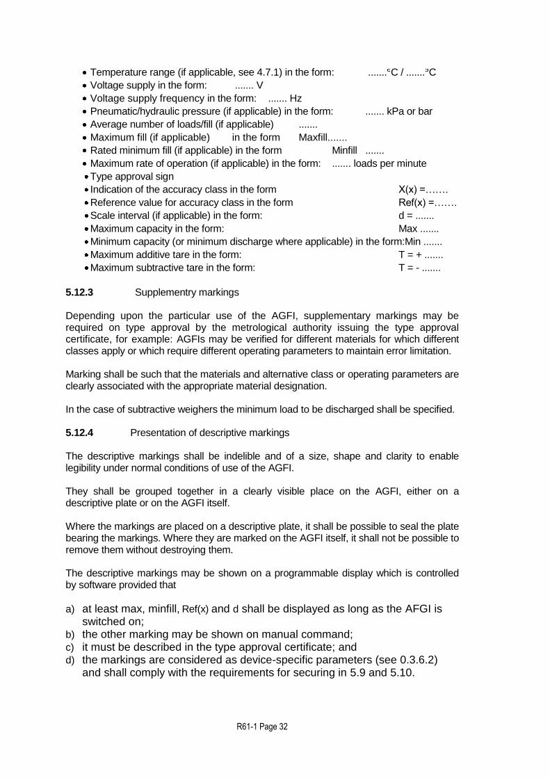
Temperature range (if applicable, see 4.7.1) in the form: ....... C / ....... C
Voltage supply in the form: ....... V
Voltage supply frequency in the form: ....... Hz
Pneumatic/hydraulic pressure (if applicable) in the form: ....... kPa or bar
Average number of loads/fill (if applicable) .......
Maximum fill (if applicable) in the form Maxfill.......
Rated minimum fill (if applicable) in the form Minfill .......
Maximum rate of operation (if applicable) in the form: ....... loads per minute
Type approval sign
Indication of the accuracy class in the form X(x) =…….
Reference value for accuracy class in the form Ref(x) =…….
Scale interval (if applicable) in the form: d = .......
Maximum capacity in the form: Max .......
Minimum capacity (or minimum discharge where applicable) in the form:Min .......
Maximum additive tare in the form: T = + .......
Maximum subtractive tare in the form: T = - .......
5.12.3 Supplementry markings
Depending upon the particular use of the AGFI, supplementary markings may be required on type approval by the metrological authority issuing the type approval certificate, for example: AGFIs may be verified for different materials for which different classes apply or which require different operating parameters to maintain error limitation. Marking shall be such that the materials and alternative class or operating parameters are clearly associated with the appropriate material designation. In the case of subtractive weighers the minimum load to be discharged shall be specified. 5.12.4 Presentation of descriptive markings The descriptive markings shall be indelible and of a size, shape and clarity to enable legibility under normal conditions of use of the AGFI. They shall be grouped together in a clearly visible place on the AGFI, either on a descriptive plate or on the AGFI itself. Where the markings are placed on a descriptive plate, it shall be possible to seal the plate bearing the markings. Where they are marked on the AGFI itself, it shall not be possible to remove them without destroying them. The descriptive markings may be shown on a programmable display which is controlled by software provided that
a) at least max, minfill, Ref(x) and d shall be displayed as long as the AFGI is switched on;
b) the other marking may be shown on manual command; c) it must be described in the type approval certificate; and d) the markings are considered as device-specific parameters (see 0.3.6.2)
and shall comply with the requirements for securing in 5.9 and 5.10.

R61-1 Page 33
When a programmable display is used, the descriptive plate on the AGFI shall bear at least the following markings:
a) type approval sign in accordance with national requirements;
b) name or identification mark of the manufacturer;
c) serial number; d) temperature range;
e) type approval number;
f) voltage supply;
g) voltage supply frequency, (if applicable)
h) pneumatic/hydraulic pressure (if applicable).
5.13 Verification marks 5.13.1 Position The AGFI shall have a place for the application of verification marks. This place shall:
a) be the part on which the mark is located and it cannot be removed from the AGFI
without damaging the marks, b) allow easy application of the mark without changing the metrological qualities of the
AGFI, c) be visible without the AGFI or its protective covers having to be removed. 5.13.2 Mounting
AGFIs required to bear verification marks shall have a verification mark support, at the place provided for above, which shall ensure the conservation of the marks. The type and method of sealing shall be determined by national prescription. 6 Control instruments Control instruments may be separate from, or an integral part of the AGFI. Control instruments may incorporate other devices including software which allows them to determine the mass of the fill(s). Where other devices and software are incorporated into control instruments they shall continue to function correctly and their metrological functions shall not be influenced. 7 Requirements for measuring instruments with respect to their environment The type of measuring instrument is presumed to comply with the following general requirements if it passes the examination and tests specified in Annex A. 7.1 Rated operating conditions Measuring instruments shall be so designed and manufactured that they do not exceed the maximum permissible errors under rated operating conditions. 7.2 Disturbances

R61-1 Page 34
Measuring instruments shall be so designed and manufactured that when exposed to disturbances, either:
a) Significant faults do not occur, i.e. the difference between the weight indication due to the disturbance and the indication without the disturbance (intrinsic error) shall not exceed the value of the significant fault specified in 0.5.2.6 , or
b) Significant faults are detected and acted upon.
NOTE: A fault equal to or less than the value specified in 0.5.2.6 is allowed irrespective
of the value of the error of indication.
7.3 Durability
The requirements in 7.1, 7.2 and 7.5 shall be met durably in accordance with the intended use of the instrument. 7.4 Application The requirements in 7.2 may be applied separately to:
a) Each individual cause of significant fault, and/or
b) Each part of the electronic instrument. The choice of whether measuring instruments are designed to: (a) withstand disturbances or (b) detect and act on significant faults is left to the manufacturerof the instrument. 7.5 Influence factors An electronic instrument shall comply with the influence factors requirements of 4.7 and shall also comply with appropriate metrological and technical requirements at a relative humidity of either 85 % (non-condensing) or 93% (condensing) at the upper limit of the temperature range of the instrument. 7.6 Indicator display test If the failure of an indicator display element can cause a false weight indication then the instrument may have a display test facility which is automatically initiated at switch-on of indication, e.g. indication of all the relevant signs of the indicator in their active and non-active states for a sufficient time to be easily observed by the operator. 7.7 Acting upon a significant fault When a significant fault has been detected, the AGFI shall either be automatically made inoperative or a visual or audible indication shall be provided automatically and shall continue until such time when the user takes action or the fault disappears. 7.8 Warm-up time During the warm-up time of an electronic instrument there shall be no indication or transmission of the result of weighing, and automatic operation shall be inhibited.
7.9 Interfaces

R61-1 Page 35
AGFIs may be equipped with interfaces which allows it to be coupled to external equipment and software devices. An interface comprises all mechanical, electrical and software devices at the communication point between instruments, peripheral and software devices. When an interface is used, the AGFI shall continue to function correctly and its metrological functions shall not be influenced by the attached external equipment or software devices or by disturbances acting on the interface. Functions that are performed or initiated via an interface shall meet the relevant requirements and conditions of clause 6. It shall not be possible to introduce into the AGFI, through an interface, functions, program modules or data structures intended or suitable to:
a) Display unclear data,
b) Falsify displayed, processed or stored weighing results,
c) Unauthorised adjustment of the AGFI. Other interfaces shall be secured in accordance with 5.2.3.
7.10 Examination and tests Examination and testing of electronic instruments is intended to verify compliance with the applicable requirements of this Recommendation and with the requirements of clause 8. 7.10.1 Examinations An electronic instrument shall be examined to obtain a general appraisal of the design and construction. 7.10.2 Performance tests An electronic instrument or electronic device, as appropriate, shall be tested as specified in Annex A to determine the correct functioning of the AGFI. Tests are to be carried out on the whole AGFI except when the size and/or configuration of the AGFI does not lend itself to testing as a unit. In such cases the electronic devices shall be tested, where possible as a simulated instrument including all electronic elements of a system which can affect the weighing result. In addition, an examination shall be carried out on the fully operational AGFI. Susceptibility that would result from the use of electronic interfaces to other equipment shall be simulated in the tests. 7.10.3 Span stability When an electronic instrument is subjected to the span stability test specified in A.7, the absolute value of the difference between the errors obtained for any two measurements shall not exceed half the maximum permissible error for influence factor tests for a near maximum capacity load.

R61-1 Page 36
PART 2 – METROLOGICAL CONTROLS AND PERFORMANCE TESTS 8 METROLOGICAL CONTROLS 8.1 General The metrological controls of AGFIs shall, in agreement with national legislation, consist of:
a) type approval,
b) initial verification,
c) subsequent verification
d) in-service inspection.
Tests should be applied uniformly by the metrological authority and should form a uniform program. Guidance for the conduct of type approval and initial verification is provided in OIML International Documents D 19 [8] and D 20 [20] respectively. For the purposes of testing, the metrological authority may require from the applicant the product (i.e. the material to be weighed), the handling equipment, the control instrument (as defined in 5.14 and A.3.6) and the personnel to assist in performing the tests. Measures to ensure durability shall be taken subject to national regulations, which shall include assessments under items (a) to (d) above. Further information about durability testing is given in Annex D. 8.2 Type Approval 8.2.1 Documentation The application for type approval shall include documentation comprising: NOTE: The numbers in parentheses in the table below refer to clauses in this
Recommendation.
Item Documentation required
1 General description of the instrument, description of the function, intended purpose of use, kind of instrument.
2 General characteristics (manufacturer; Class, Max, Min, X(x), Ref(x), temperature range, voltage, etc.).
3 List of descriptions and characteristic data of all devices and modules of the AGFI.
R61-1 Page 37
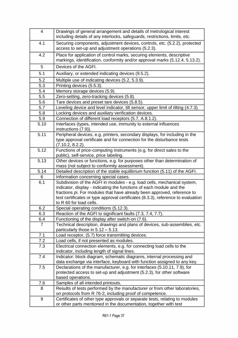
4 Drawings of general arrangement and details of metrological interest including details of any interlocks, safeguards, restrictions, limits, etc.
4.1 Securing components, adjustment devices, controls, etc. (5.2.2), protected access to set-up and adjustment operations (5.2.3).
4.2 Place for application of control marks, securing elements, descriptive markings, identification, conformity and/or approval marks (5.12.4, 5.13.2).
5 Devices of the AGFI.
5.1 Auxiliary, or extended indicating devices (9.5.2).
5.2 Multiple use of indicating devices (5.2, 5.3.9).
5.3 Printing devices (5.5.3).
5.4 Memory storage devices (5.9).
5.5 Zero-setting, zero-tracking devices (5.8).
5.6 Tare devices and preset tare devices (5.8.5).
5.7 Leveling device and level indicator, tilt sensor, upper limit of tilting (4.7.3).
5.8 Locking devices and auxiliary verification devices.
5.9 Connection of different load receptors (5.7, A.8.1.2).
5.10 Interfaces (types, intended use, immunity to external influences instructions (7.9)).
5.11 Peripheral devices, e.g. printers, secondary displays, for including in the type approval certificate and for connection for the disturbance tests (7.10.2, 8.2.2).
5.12 Functions of price-computing instruments (e.g. for direct sales to the public), self-service, price labeling.
5.13 Other devices or functions, e.g. for purposes other than determination of mass (not subject to conformity assessment).
5.14 Detailed description of the stable equilibrium function (5.11) of the AGFI.
6 Information concerning special cases.
6.1 Subdivision of the AGFI in modules - e.g. load cells, mechanical system, indicator, display - indicating the functions of each module and the fractions pi. For modules that have already been approved, reference to test certificates or type approval certificates (8.3.3), reference to evaluation to R 60 for load cells.
6.2 Special operating conditions (5.12.3).
6.3 Reaction of the AGFI to significant faults (7.3, 7.4, 7.7).
6.4 Functioning of the display after switch-on (7.6).
7 Technical description, drawings and plans of devices, sub-assemblies, etc. particularly those in 5.12 – 5.13.
7.1 Load receptor, (5.7) force transmitting devices.
7.2 Load cells, if not presented as modules.
7.3 Electrical connection elements, e.g. for connecting load cells to the indicator, including length of signal lines.
7.4 Indicator: block diagram, schematic diagrams, internal processing and data exchange via interface, keyboard with function assigned to any key.
7.5 Declarations of the manufacturer, e.g. for interfaces (5.10.11, 7.9), for protected access to set-up and adjustment (5.2.3), for other software based operations.
7.6 Samples of all intended printouts.
8 Results of tests performed by the manufacturer or from other laboratories, on protocols from R 76-2, including proof of competence.
9 Certificates of other type approvals or separate tests, relating to modules or other parts mentioned in the documentation, together with test
R61-1 Page 38
protocols.
10 For software controlled AGFIs or modules, additional documents according to 5.10 and Annex B).
11 Drawing or photo of the AGFI showing the principle and the location of verification and securing marks are to be applied, which is necessary to be included in the OIML Certificate or Test Report.
8.2.2 General requirements Type evaluation shall be carried out on one or more and normally not more than three AGFIs that represent the definitive type. At least one of the AGFIs shall be submitted in a form suitable for simulation testing in a laboratory and shall include the whole of the electronics which affect the weighing result except in the case of an associative weigher where only one representative weighing module may be included. The evaluation shall consist of the tests specified in 8.2.3. MPE for static tests shall be apportioned in accordance with 8.2.3.3 to parts of the AGFI that are tested seperately. 8.2.3 Type evaluation The submitted documents shall be examined and tests carried out to verify that the AGFI comply with:
a) The requirements specified for static tests in 4 and 5,
b) The technical requirements in 6,
c) The requirements in 8 for electronic instruments, where applicable.
The metrological authority shall:
a) Conduct the tests in a manner which prevents an unnecessary commitment of resources,
b) Permit the results of these tests to be assessed for initial verification
8.2.3.1 Operational tests for type evaluatiuon Tests for type evaluation shall be conducted:
a) In accordance with the appropriate parts of 6. b) Under the normal conditions of use for which the AGFI is intended, and c) In accordance with the material test methods given in 6, using material
that is representative of a product for which the AGFI is designed to assess compliance with the technical requirements of 6.
For software-controlled AGFIs, the additional requirements in 5.10 and in Annex B apply.

R61-1 Page 39
8.2.3.2 Influence factor tests Influence factors shall be applied to the AGFI or simulator during simulation tests in a manner that will reveal a corruption of the weighing result of any weighing process to which the AGFI could be applied, in accordance with:
a) 4.7 for all AGFIs,
b) 4.6 for electronic AGFIs.
8.2.3.3 Apportioning of errors Where parts of the AGFI are examined separately in the process of type approval, the following requirements apply: The error limits applicable to a part which is examined separately are equal to a fraction Pi of the maximum permissible errors or the allowed variations of the indication of the complete AGFI. The fractions for any part have to be taken for the same accuracy class as for the complete AGFI incorporating the part. The fractions pi shall satisfy the following equation:
(p12 + p2
2 + p32 + ....) 1
The fraction pi shall be chosen by the manufacturer of the part and shall be verified by an appropriate test. However, the fraction shall not exceed 0.8 and shall not be less than 0.3, when more than one part contributes to the effect in question. If the metrological characteristics of the load cell or other major component has been evaluated in accordance with the requirements of any OIML International Recommendation (e.g. OIML R 60 [6] for load cells), that evaluation shall be used to aid in the type evaluation if so requested by the applicant. NOTE: As the requirements of this clause only apply to the AGFI submitted for type
evaluation and not to those subsequently submitted for verification, the means by which it will be possible to determine whether the appropriate maximum permissible error or maximum allowable variation has been exceeded will be decided mutually between the metrological authority and the applicant. The means may be for example:
The provision or adaptation of the indicating device to give the required resolution or appropriate increment or scale interval, or
The use of change point weights, or
Any other means mutually agreed.
Acceptable solution
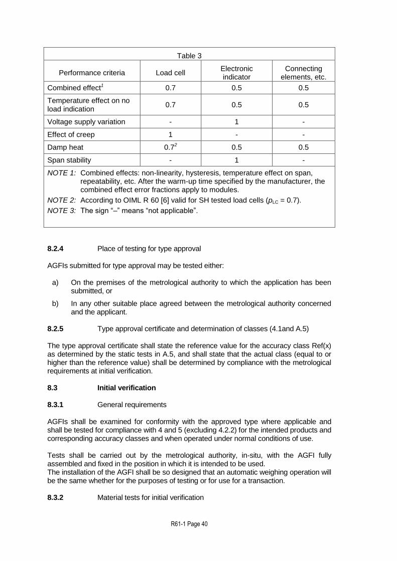
For AGFIs incorporating the typical modules (see 0.3.11) the fractions pi may have the values given in Table 3, which takes into account the fact that the modules are affected in a different manner depending on the different performance criteria.
R61-1 Page 40
Table 3
Performance criteria Load cell Electronic indicator
Connecting elements, etc.
Combined effect1 0.7 0.5 0.5
Temperature effect on no load indication
0.7 0.5 0.5
Voltage supply variation - 1 -
Effect of creep 1 - -
Damp heat 0.72 0.5 0.5
Span stability - 1 -
NOTE 1: Combined effects: non-linearity, hysteresis, temperature effect on span, repeatability, etc. After the warm-up time specified by the manufacturer, the combined effect error fractions apply to modules.
NOTE 2: According to OIML R 60 [6] valid for SH tested load cells (pLC = 0.7).
NOTE 3: The sign “–” means “not applicable”.
8.2.4 Place of testing for type approval AGFIs submitted for type approval may be tested either:
a) On the premises of the metrological authority to which the application has been
submitted, or b) In any other suitable place agreed between the metrological authority concerned
and the applicant. 8.2.5 Type approval certificate and determination of classes (4.1and A.5) The type approval certificate shall state the reference value for the accuracy class Ref(x) as determined by the static tests in A.5, and shall state that the actual class (equal to or higher than the reference value) shall be determined by compliance with the metrological requirements at initial verification. 8.3 Initial verification 8.3.1 General requirements AGFIs shall be examined for conformity with the approved type where applicable and shall be tested for compliance with 4 and 5 (excluding 4.2.2) for the intended products and corresponding accuracy classes and when operated under normal conditions of use. Tests shall be carried out by the metrological authority, in-situ, with the AGFI fully assembled and fixed in the position in which it is intended to be used. The installation of the AGFI shall be so designed that an automatic weighing operation will be the same whether for the purposes of testing or for use for a transaction. 8.3.2 Material tests for initial verification
R61-1 Page 41
In-situ material tests shall be done:
a) In accordance with the descriptive markings given in 5.12, b) Under the normal conditions and with the products for which the AGFI is intended. c) In accordance with the test method in 6 and the material tests procedure given in
A.8.2. Accuracy requirements shall be applied in accordance with the appropriate parts of 5.
8.3.3 Conduct of the tests
The metrological authority:
a) Shall conduct the tests in a manner which prevents an unnecessary commitment of resources,
b) May, where appropriate and to avoid duplicating tests previously done on the
AGFI for type evaluation under 8.2, use the test results from type evaluation for initial verification.
8.3.4 Determination of accuracy class X(x) For class X(x) AGFIs the metrological authority shall:
a) Determine the accuracy class for the materials used in the tests in accordance with
8.2.5 by reference to the material test results from A.8 and the error limitation specified in 4.2.1 and 4.2.3 for initial verification,
b) Verify that accuracy classes marked in accordance with descriptive markings in 5.12
are equal to or greater than the accuracy classes determined as above. The accuracy class marking required in accordance with 5.12 shall show the same accuracy class as for which the type was approved and which was laid down in the approval certificate.
8.3.5 Appropriate material designation Marking shall be such that the materials and alternative class or operating parameters are clearly associated with the appropriate material designation in accordance with 5.12.
8.4 Subsequent verification Subsequent verifcation shall be carried out in accordance with the same provisions as in 8.3 for initial verification. Further information regarding durability testing as part of subsequent control is given in Annex D.
8.5 In-service inspection

R61-1 Page 42
In-service Inspection shall be carried out in accordance with the same provisions as in 8.3.1 and 8.3.2 9 TEST METHODS 9.1 Determination of the mass of individual fills The mass of individual fills is determined using either the separate verification method given in 9.5.1 or the integral verification method given in 9.5.2. 9.2 Conduct of material tests
9.2.1 Values of the mass of the fills
a) The tests shall be carried out on fills using loads at, or near to, the Max and also at, or near to, the Minfill of the AGFI.
b) Cumulative weighers shall be tested as in (a) with the maximum practical
number of loads per fill and also with the minimum number of loads per fill, and associative weighers as in (a) with the average (or optimum) number of loads per fill (see 0.4.10).
c) If the Minfill is less than one third of the Maxfill then tests shall also be carried
out near the centre of the load weighing range. 9.2.2 Types of test loads
For type evaluation, the materials used for test loads shall be as specified in 8.2.3.1 and for initial verification and in-service inspection material used for test loads shall be as specified in 8.3.2. 9.2.3 Condition of tests All tests shall be conducted with any adjustable parameter critical to metrological integrity, e.g. final feed time or rate, set to the most onerous condition allowed by the manufacturer’s printed instructions and incorporated in the descriptive markings. Prior to the start of a new test the AGFI shall be operated for a time period under normal operating conditions to enable stability, i.e until all the principal parts, devices and parameters such as warm-up, temperature, indications, etc, critical to metrological integrity have stabilized according to the manufacturer’s printed instructions. During this stabilization period the fills shall not be included in the test. Any correction device, e.g. in-flight correction and/or automatic zero-setting fitted to an AGFI shall be operated during the tests according to the manufacturer’s printed instructions. The initial fills after the change between Max and Min shall be included in the test unless the AGFI bears a clear warning to discard the stated number of fills after a change to the AGFI’s settings. 9.3 Number of fills The minimum number of individual test fills depends upon the preset value (FP) as specified in Table 4.

R61-1 Page 43
Table 4 – Number of test fills
Preset value of the fills FP (kg)
Minimum number of test fills (n)
1 kg < 10 kg < 25 kg <
FP FP FP FP
1 kg
10 kg
25 kg
60 fills 30 fills 20 fills 10 fills
9.4 Accuracy of standards The control instrument and standard weights used in testing shall ensure the checking of the test fills to an error not greater than one third of the MPD and MPSE (as appropriate) for automatic weighing (details as given in 4.2.2 and 4.2.3 respectively). 9.5 Material test methods 9.5.1 Separate verification method The separate verification method requires the use of a (separate) control instrument (details as given in 5.14 and A.3.6) to find the conventional true of the mass of the test fill. 9.5.2 Integral verification method With this method the AGFI being tested is used to determine the conventional value of the mass of the test fill. The integral verification method shall be conducted using either:
a) An appropriately designed indicating device, or
b) An indicating device with standard weights to assess the rounding error.
The total uncertainty of the test method (separate or integral verification) shall be not greater than one third of the maximum permissible error for the AGFI. NOTE1: The integral verification method depends on determining the masses of the
loads. Error limitation as specified in 4.2 are for the mass of the fill. If it is not possible to ensure that in normal operation all of the load is discharged at each cycle of operation, i.e. that the sum of the loads is equal to the fill, then the separate verification method (details as given in 9.5.1) must be used.
NOTE 2: When using the integral verification method for a cumulative weighing instrument a sub-division of the test fill is unavoidable. When calculating the conventional value of the mass of the test fill, it is necessary to consider the increased uncertainty due to the division of the test fill.
9.5.2.1 Interruption of automatic operation An automatic filling operation of a test fill shall be initiated as for normal operation. However the automatic operation shall be interrupted twice during each filling cycle in the following conditions:
a) on the AGFI where the fill is weighed in the load receptor
R61-1 Page 44
After filling the load receptor (a)
After discharge of the load receptor (b)
b) on the AGFI where the load is weighed in a container on the load receptor
After tare balancing the empty container (b)
After filling the container (a)
c) on a subtractive weigher
After tare balancing the filled load receptor (a)
After discharge of the fill from the load receptor (b)
An automatic operation shall not be interrupted during consecutive weighing cycles if the interruption would significantly affect the mass of the fill. In this case, one or two fills shall be discharged in automatic operation without being checked, between the fills that are checked.
(a) Pre-discharge (full) interrupt The automatic operation shall be interrupted immediately after the feed of material has ceased and the load receptor(s), or the container on the load receptor has been filled, or on a subtractive weigher the filled load receptor has been tare balanced. When the load receptor(s) has (have) stabilized, the net weight of the fill indicated or determined by balancing with standard weights shall be recorded and the AGFI switched back to automatic operation.
(b) Post-discharge (empty) interrupt The automatic operation shall be interrupted after the load(s) has (have) been discharged, or a new container has been placed on the load receptor and its weight has been tare balanced, and the load receptor(s) is (are) ready to receive a further load. When the load receptor(s) has (have) stabilized, the empty load receptor weight indicated or determined by balancing with standard weights shall be recorded and the AGFI switched back to automatic operation. 9.6 Preset value The indicated preset value of the fill shall be noted where applicable. 9.7 Mass and average value of the test fills The test fill shall be weighed on a control instrument and the result shall be considered as being the conventional true value of the test fill. The average value of all the fills in the test shall be calculated and noted. 9.8 Deviation for automatic weighing The deviation for automatic weighing used to determine compliance of each fill with the maximum permissible deviation for automatic weighing (specified in 4.2.1) shall be the difference between the conventional value of the mass of the test fill (as defined in 9.7) and the average value of all the fills in the test.

R61-1 Page 45
9.9 Preset value error for automatic weighing The preset value error for automatic weighing used to determine compliance with 4.2.3 shall be the difference between the average value of the conventional value of the mass of the test fills (as defined in 9.7) and the preset value of the fills.
R61-1 Page 46
ANNEX A
PROCEDURES FOR TESTS ON AGFIs (Mandatory)
A.1 Examination for type approval A.1.1 Documentation Review the documentation that is submitted to determine if it is adequate and correct. For type approval the documentation shall be as specified in 8.2.1. A.1.2 Compare construction with documentation Examine the various devices of the AGFI to ensure compliance with the documentation in accordance with 7.3.
A.1.3 Metrological requirements Note the metrological characteristics using the checklist in the test report format in OIML R 61-3 A.1.4 Technical requirements Examine the AGFI for conformity with the technical requirements of 5 and 8, using the checklist given in the test report format R 61-3. A.1.5 Functional requirements Examine the AGFI for conformity with functional requirements according to details given in 8, using the checklist given R 61-3 Test report format. A.2 Examination for initial verification A.2.1 Compare construction with documentation Examine the AGFI for conformity with the approved type in accordance with the requirements in 8.3.1. A.2.2 Descriptive markings Check the descriptive markings in accordance with 5.12 and use the checklist given in OIML R 61-3.
A.3 General test requirements
A.3.1 Power supply (in accordance with 4.7.2) Power up the equipment under test (EUT) for a time period equal to or greater than the warm-up time specified by the manufacturer and maintain the EUT energised for the duration of each test. A.3.2 Zero-setting (in accordance with 5.8)

R61-1 Page 47
Using the manual or semi-automatic zero-setting facility, adjust the EUT as closely as practicable to zero prior to each test, and do not readjust it at any time during the test, except to reset if a significant fault has been indicated. Status of automatic zero facilities shall be as specified for each test. A.3.3 Temperature (in accordance with 4.7.1) The tests shall be performed at a steady ambient temperature, usually normal ambient temperature unless otherwise specified. The temperature is deemed to be steady when the difference between the extreme temperatures noted during the test does not exceed
one-fifth of the temperature range of the AGFI without being greater than 5 C, and the
rate of change does not exceed 5 C per hour. The handling of the AGFI shall not result in condensation of water on the AGFI.
A.3.4 Recovery After each test the AGFI shall be allowed to recover sufficiently before the next test.
A.3.5 Pre-loading Before each weighing test the AGFI shall be pre-loaded to Max, except for the tests in A.5.2 and A.6.2.2. A.3.6 Control instruments (0.2.2.4 and 6) A.3.6.1 Accuracy of test system (in accordance with 9.4) The control instrument and standard weights used in testing shall ensure the determination of the weight of test loads and fills to an error not greater than one third of the MPE of the AGFI in accordance with 9.4 (a) or (b) for material tests
NOTE: Accuracy requirements for the test system depend on the error limitation which depends on the accuracy class. However the class is determined from the results of the tests. It is therefore necessary that the metrological authority responsible for testing should be informed of the best accuracy class that may be achieved, prior to commencement of testing.
A.3.6.2 Use of standard weights to assess rounding error of indication A.3.6.2.1 General method to assess error of indication prior to rounding For instruments with digital indication having a scale interval d, changeover points may be used to interpolate between scale intervals i.e. to determine the indication of the instrument, prior to rounding, as follows. At a certain load, L, the indicated value, I, is noted. Additional weights of say 0.1 d are successively added until the indication of the instrument is increased unambiguously by one scale interval (I + d). The additional load ΔL added to the load receptor gives the indication, P, prior to rounding by using the following formula: P = I + 0.5 d - ΔL

R61-1 Page 48
The error prior to rounding is: E = P - L = I + 0.5 d - ΔL - L Example: A weighing instrument with a scale interval, d, of 5 g is loaded with 1 kg and thereby indicates 1 000 g. After adding successive weights of 0.5 g, the indication changes from 1 000 g to 1 005 g at an additional load of 1.5 g. Inserted in the above formula these observations give: P = (1 000 + 2.5 - 1.5) g = 1 001 g Thus the true indication prior to rounding is 1 001 g, and the error of indication prior to rounding is: E = (1 001 - 1 000) g = +1 g A.3.6.2.2 Correction for error at zero Evaluate the error at zero load, (E0) by the method of A.3.6.2.1. Evaluate the error at load L, (E) by the method of A.3.6.2.1 The corrected error prior to rounding, (Ec) is: Ec = E - E0 Example: if, for the example in A.3.6.2.1, the error calculated at zero load was: E0 = +0.5 g, the corrected error is: Ec = + 1 - (+ 0.5) = +0.5 A.3.7 Indication of a digit smaller than d
If an instrument with digital indication has a device for displaying temporarily the indication with a smaller scale interval (not greater than 0.2 d), this device may be used to determine the error. If a device is used, it should be noted in the Test Report. A.4 Test program A.4.1 Type evaluation (in accordance with 8.2.2 and 8.2.3) The following tests shall normally be applied for type evaluation: Examination for type approval in A.1,
a) Static tests in A.5,
b) Influence factor and disturbance tests given in A.6,
c) Span stability test in A.7, and
d) Material tests in A.8.1 A.4.2 Non-automatic weighing instruments (in accordance with 2)

R61-1 Page 49
For instruments in which the weighing function is provided by a non-automatic weighing instrument that has been approved in respect of conformity with OIML R 76 [7], the tests specified in A.4.1 may be omitted where equivalent test results specified in OIML R 76 [7] prove conformity with the relevant parts of OIML R 61. Use of OIML R 76 [7] test results shall be recorded in the test report checklist and summary in OIML R 61-3. A.4.3 Initial verification (in accordance with 8.3) The following tests shall normally be applied for initial verification: a) Examination for initial verification in A.2, and b) Material tests at initial verification in A.8.2. Static weighing test method (as detailed in A.5.4) may also be used if necessary to verify the indicator for the integral verification method of material tests. A.5 Static tests (type approval stage) A.5.1 General (in accordance with 8.2.2 and 8.2.3.2) Electronic instruments or instrument simulators are required to have a load indicator, or an interface allowing access to a quantity that can be calibrated to provide an indication of load so that the effect of influence quantities may be tested and the reference accuracy class determined. This facility also enables testing of warm-up time and zero-setting and tare devices where applicable. The static weighing tests are normally done as part of influence quantity testing. Limits for warm-up time tests and for accuracy of zero- and tare-setting tests are derived from 4.2, and are therefore dependent on the reference accuracy class Ref(x). Therefore the results of these tests must be evaluated after Ref(x) has been determined as specified in 8.2.5. A.5.2 Warm-up time (in accordance with 7.8) This test is to verify that metrological performance is maintained in the period immediately after switch-on. The method is to check that automatic operation is inhibited until a stable indication is obtained and to verify that the zero variation and the errors at Max comply with the specified requirements during the first 30 minutes of operation. If the zero is set as part of the normal automatic weighing cycle then this function shall be enabled or simulated as part of the test. Other test methods which verify that metrological performance is maintained during the first 30 minutes of operation may be used. a) Disconnect instrument from the power supply for a period of at least 8 hours prior to
the test. b) Reconnect instrument and switch on while observing the load indicator. c) Check that it is not possible to initiate automatic weighing until the indicator has
stabilized. d) As soon as the indication has stabilized, set the instrument to zero if this is not done
automatically.

R61-1 Page 50
e) Determine the error at zero by the method of A.3.4.2.1, and specify this error as E0I
(error of initial zero-setting) at first and as E0 (zero-setting error) when repeating this step.
f) From (e) verify that E0I is not greater than the MPE specified in 5.8.2. g) Apply a static load close to Max. Determine the error by the method of A.3.4.2.1
and A.3.4.2.2. h) Repeat steps (e), (f) and (g) (every minute within the first 5 minutes, between 5 and
15 minutes every two minutes, after 15 minutes take the readings every five minutes. Observe whether the drift has stopped after 30 minutes. If not, continue taking the readings until warm-up process has completely finished and the indication both at zero and Max remain stable (show no further drift).
i) From (g) and (h) verify that:
1) The error (corrected for zero error) for a static load close to Max is not greater than the MPE specified in 4.2.2,
2) After each time interval the zero-variation error (E0 - E0I) is not greater than the
MPE specified in 5.8.2. A.5.3 Zero-setting and tare devices (in accordance with 5.8) A.5.3.1 General Unless it is clear that zero and tare functions are performed by the same process then both functions shall be tested separately. Zero-setting and taring may be by more than one mode, for example:
a) Nonautomatic or semi-automatic,
b) Automatic at switch-on,
c) Automatic at start of automatic operation,
d) Automatic at programmable time intervals,
e) Automatic as part of weighing cycle. It is normally only necessary to test the accuracy of zero-setting and taring in one mode if it is clear that the same process is used for each mode. If zero-setting or taring is set as part of the automatic weighing cycle then this mode shall be tested. To test automatic zero-setting or taring it is necessary to allow the AGFI to operate through the appropriate part of the automatic cycle and then to halt the AGFI before testing. The range and accuracy of zero-setting shall be tested by applying loads as specified below in nonautomatic (static) operation to the load receptor after the instrument is halted.
A.5.3.2 Range of zero-setting
A.5.3.2.1 Initial zero-setting

R61-1 Page 51
(a) Positive range With the load receptor empty, set the instrument to zero. Place a test load on the load receptor and set the instrument to zero again. Continue this process until it does not reset to zero. The maximum load that can be re-zeroed is the positive portion of the initial zero-setting range. (b) Negative range 1) Remove any load from the load receptor and set the instrument to zero. Then, if
possible, remove any non-essential components of the load receptor. If, at this point, the instrument can be reset to zero with the zero setting device, the mass of the non-essential components is used as the negative portion of the initial zero-setting range.
2) If the instrument cannot be reset to zero with the non-essential components
removed, add loads to any live part of the scale until the instrument indicates zero again.
3) Then remove the loads and, after each load is removed, use the zero setting
device. The maximum load that can be removed while the instrument can still be reset to zero by the zero-setting device is the negative portion of the initial zero-setting range.
4) The initial zero-setting range is the sum of the positive and negative portions.
5) Alternatively, if it is not possible to test the negative range of initial zero setting by
removing parts of the instrument, the instrument may be temporarily re-calibrated with a test load applied before step (3) above. (The test load applied for the temporary re-calibration should be greater than the permissible negative portion of the initial zero setting range which can be calculated from the result of the positive range test).
6) If it is not possible to test the negative portion of the initial zero-setting range by
these methods then only the positive part of the zero-setting range need be considered.
7) Reassemble or recalibrate the instrument for normal use after the above tests.
A.5.3.2.2 Automatic zero-setting range Remove the non-essential parts of the load receptor or re-calibrate the instrument as described in A.5.3.2.1 and place weights on the live part of the scale until it indicates zero. Remove weights in small amounts and after each weight is removed allow the instrument to operate through the appropriate part of the automatic cycle so as to see if the instrument is reset to zero automatically. The maximum load that can be removed so the instrument can still be reset to zero is the zero-setting range. A.5.3.3 Accuracy of zero-setting a) When the load receptor is empty, zero the AGFI in a mode as determined by A.5.3.1.

R61-1 Page 52
b) Add load(s) to the load receptor to determine the additional load at which the
indication changes from zero to one scale interval above zero.
c) Calculate the error at zero according to the method described in A.3.6.2.1.
d) Verify that the zero-setting error is within the limit specified in 5.8.2 A.5.3.4 Accuracy of taring Accuracy of the tare device shall be tested at the maximum tare as specified by the manufacturer.
a) Place the maximum tare load on the load receptor, operate the tare function key immediately in a mode as determined by A.5.3.1 to enable the equilibrium device to release the tare function.
b) Add load(s) to the load receptor to determine the additional load at which the
indication changes from zero to one scale interval above zero.
c) Calculate the error according to the method described in A.3.6.2.1.
d) Verify that the zero-setting error is within the limit specified in 5.8.2
A.5.3.5 Frequency of automatic zero-setting and taring This test does not need to be performed for AGFIs that have automatic zero-setting as part of every automatic weighing cycle. If the zero-setting device is not part of the automatic weighing cycle but operates with a programmable time interval, the value for maximum permissible time interval for automatic zero-setting shall be determied as follows: a) The maximum allowable rate of change of a steady ambient temperature is 5 °C
per hour as specified in A.3.3. b) The maximum zero-setting error (5.8.2) is determined as follows:
(Ezsemax) 0.25 MPD in-service x Minfill x Ref(x) (1) c) The maximum zero-checking error (5.8.3.2) is determined as follows:
(Ezcmax) 0.5 MPD in-service x Minfill x Ref(x) (2)
so the maximum zero-variation ( zmax) is: (Ezcmax – Ezsemax) = 0.25 MPD in-service x Minfill x Ref(x) (3)
d) In accordance with A.6.2.2, the maximum zero-variation ( zmax) per 5oC is less than or equal to 0.25 MPD in-service:
zmax per 5 °C 0.25 MPD in-service x Minfill x Ref(x) (4) e) Substituting the 5 °C per hour steady ambient temperature from paragraph (a)

R61-1 Page 53
For zmax per 5 °C in equation (4) gives:
zmax per hour 0.25 MPD in-service x Minfill x Ref(x) (5) Since equations (5) and (4) are identical, an AGFI which needs the maximum allowable variation given in A.6.2.2 has a maximum programmable time interval of automatic zero-setting or taring 1 hour. If the AGFI needs less or more of the maximum zero-variation given in A.6.2.2, the maximum programmable time interval of automatic zero-setting or taring may be increased or decreased proportionally. In exceptional situations the effects of external factors such as operating temperatures, environmental conditions, stickiness of the product being handled, etc, may determine the maximum programmable time interval of automatic zero setting or taring, which shall be in accordance with 5.8.3.2. A.5.4 Static weighing test method for type evaluation (in accordance with 8.2.3) Apply test loads from zero up to and including Max, and similarly remove the test loads back to zero. The test loads selected shall include values close to Max and Min and other critical loads as specified in 9.2.1(c), subject to requirements of this Annex. Determine the error at each test load, using the standard weights assessment procedure of A.3.6.2, if necessary, to obtain the accuracy of the test system as specified in A.3.6.1. It should be noted that when loading or unloading, the load shall be progressively increased or progressively decreased. A.5.5 Determination of reference accuracy class, Ref(x) (in accordance with 8.2.5) The static weighing tests during application of influence factors (as appropriate) shall be used at type evaluation stage to establish the reference value for accuracy class, i.e. Ref(x), as follows: a) Perform static weighing tests for influence factors and loads as specified in this
Annex. b) Determine the MPE for influence factor tests for class X(1), MPE(1) for each load as
follows:
MPE(1) = 0.25 MPD(1) * (pi, if applicable) in-service inspection for the fill value equal to the
load. For example, with a load of 10kg, the MPE for influence factor tests as specified in 4.2.2 will be calculated thus:
MPE(1) = pi x (0.25 x 1.5% x 10,000g)
where
pi (as specified in 8.2.3.3) is a fraction of the MPE applied to a part of the AGFI which is examined seperately
MPE(1) is error limit specified in Table 1 for mass of fill.

R61-1 Page 54
c) (Calculate [│Error│ / MPE(1)] for each load Where: Error is the corrected error calculated at zero load, in units of mass, as specified in A.3.6.2.2. d) From (3) determine the maximum value of [│Error│ / MPE(1)] for all the influence
factor tests, i.e. [│Error│ / MPE(1)]Max for all influence factor tests
e) Determine Ref(x) from [│Error│ / MPE(1)]Max such that:
Ref(x) [│Error│ / MPE(1)]Max and Ref(x) = 1 x 10k, 2 x 10k, or 5 x 10k,
the index k being a positive or negative whole number or zero. Values for significant fault shall then be calculated from the MPD for the reference class.
A.6 Influence factor and disturbance tests A.6.1 Test conditions A.6.1.1 General requirements Prior to a test, the error at zero shall be assessed and corrected by the methods given in A.3.6.2 and in A.3.6.2.2. Influence factor and disturbance tests specified in 7.2 and 7.5 are intended to verify that electronic instruments can perform and function as intended in the environment and under the conditions specified. Each test indicates, where appropriate, the reference condition under which the intrinsic error is determined. It is generally not possible to apply the influence factors or disturbances to AGFIs which are processing material automatically. The AGFI shall therefore be subjected to the influence factors or disturbances under static conditions or simulated operation as defined herein. The permissible effects of the influence factors or disturbances, under these conditions, are specified for each case. When the effect of one influence factor is being evaluated, all other factors are to be held relatively constant, at a value close to normal. After each test the AGFI shall be allowed to recover sufficiently before the following test. Where parts of the AGFI are examined separately, errors shall be apportioned in accordance with details given in 8.2.3.3. The operational status of the AGFI or simulator shall be recorded for each test. When the AGFI is connected in other than a normal configuration, the procedure shall be mutually agreed on by the approving authority and the applicant.

R61-1 Page 55
A.6.1.2 Simulator requirements A.6.1.2.1 General The simulator for influence factor and disturbance tests should include all electronic devices of the weighing system. A.6.1.2.2 Load cell A number of tests can be performed with either a load cell or a simulator but both have to fulfill the requirements in the following paragraph. However the disturbance tests should be performed with a load cell or a weighing platform with load cell being the most realistic case. If a simulator is used to test a module, the repeatability and stability of the simulator should make it possible to determine the performance of the module with at least the same accuracy as when a complete instrument is tested with weights, the mpe to be considered being those applicable to the module. If a simulator is used, this shall be noted in the Test Report Format and its traceability referenced. A.6.1.2.3 Interfaces (details as given in 7.9) Susceptibility that would result from the use of electronic interfaces to other equipment shall be simulated in the tests. For this purpose it is sufficient to connect 3m of interface cable terminated to simulate the interface impedance of the other equipment or instead suitable peripheral equipment may be connected to the interfaces. A.6.1.2.4 Documentation Simulators shall be defined in terms of hardware and functionality by reference to the AGFI under test, and by any other documentation necessary to ensure reproducible test conditions. This information shall be attached to, or be traceable from the test report. A.6.1.3 Multi-load AGFIs and test limits For AGFIs where the fill may consist of more than one load, the metrological authority or manufacturer shall consider the design of the AGFI and the method of test, to ensure that the requirements in 4.4 are met. A.6.1.3.1 Multi-load AGFIs and significant fault vlaue The f examples in Annex F.1 show how to determine the value of a significant fault on selective combination weighers and cumulative weighers when testing. A.6.1.3.2 Multi-load AGFIs and influence factor mpe determination The examples in Annex F.2 show how to determine the maximum permissible error for influence factor testing for selective combination weighers and cumulative weighers when testing.

R61-1 Page 56
A.6.2 Influence factor tests
Summary of tests
§ Test Characteristic under test
Conditions applied
A.6.2.1 Temperature with static load Influence factor MPE
A.6.2.2 Temperature effect on no-load indication
Influence factor MPE
A.6.2.3 Damp heat test Influence factor MPE
A.6.2.4 AC mains voltage variation Influence factor MPE
A.6.2.5 DC mains voltage variation Influence factor MPE
A.6.2.6 Low voltage of internal battery (not connected to the mains supply)
Influence factor MPE
A.6.2.7 Power from external 12V and 24V road vehicle batteries
Influence factor MPE
A.6.2.8 Tilting Influence factor MPE
NOTE: Although IEC Standards are mentioned, the requirements of OIML R61 have to be fulfilled. Differences should be taken into account. A.6.2.1 Prescribed temperatures (in accordance with 4.7.1.1) Prescribed temperatures for static tests are carried out according to basic standard IEC Publication 60068-2-1[10], IEC Publication 60068-2-2[11], and and IEC 60068-3-1[12],and according toTable 5.
Table 5 – Static temperature tests
Environmental Phenomena
Test specification Test set-up
Temperature Reference of 20 C
Specified high for 2 hours IEC 60068-2-2
Specified low for 2 hours IEC 60068-2-1
Temperature of 5 °C, if the specified low temperature is
0 °C
IEC 60068-2-1
Reference of 20 C
NOTE 1: Use IEC 60068-3-1[12] for background information. NOTE 2: The static temperatures test is considered as one test.
Supplementary information to the IEC test procedures: Object of the test: To verify compliance with the provisions given in 4.7.1.1
under conditions of dry heat (non condensing) and cold. The test A.6.2.2 may be combined with this test.

R61-1 Page 57
Condition of the EUT: 16 hours switched on at reference environmental conditions
The EUT is switched on for at least the warm-up time specified by the manufacturer. During the test the electrical power supplied to the EUT shall not be switched off.
The zero-setting and zero-tracking facilities shall be enabled as for normal operation.
If the test is performed together with A.7.2.2 automatic zero-setting and zero tracking shall not be in operation.
Stabilization: Minimum of 2 hours at each temperature under "free air" conditions. “Free air” conditions mean a minimum air circulation to keep the temperature at a stable level.
Temperature: As specified in 4.7.1.1.
Temperature sequence: Reference temperature of 20 C Specified high temperature Specified low temperature
Temperature of 5 C
Reference temperature of 20 C
Number of test cycles: At least one cycle.
Weighing test: After stabilization at the reference temperature and again at each specified temperature conduct the following: Adjust the EUT as close to zero indication as practicable. It is important to ensure that the test result is unaffected by the automatic zero-setting function which should therefore be disabled. The EUT shall be tested with at least five different static test loads (or simulated loads) including Max and Min capacities. When loading or unloading weights the load must be respectively increased or decreased monotonically. Record the following data:
a) Date and time b) Temperature c) Relative humidity d) Test load e) Indications f) Errors g) Functional performance
Maximum allowable variations: All functions shall operate as designed. All errors shall be within the maximum permissible errors specified in 4.2.2.
A.6.2.2 Temperature effect on no-load indication (in accordance with 4.7.1.3)

R61-1 Page 58
NOTE: This test should not be performed for instruments that have automatic zero- setting as part of every automatic weighing cycle.
Object of the test: To verify compliance with the provisions given in 4.7.1.3 under
conditions of dry heat (non condensing) and cold. This test may be combined with the test in A.6.2.1.
The instrument is set to zero, the temperature is then changed to the prescribed highest
and lowest temperatures as well as at 5 C. After stabilization, the error of the zero
indication is determined. The change in zero indication per 5 C is calculated. The
changes of these errors per 5 C are calculated for any two consecutive temperatures of this test.
The errors at zero shall then be additionally determined immediately before changing to the next temperature and after the 2-hour period after the instrument has reached stability at this temperature. Maximum allowable variations: The change in zero indication shall not vary by more than
the MPE for influence factor tests as specified in 4.2.2 for the Minfill of the AGFI, for a temperature difference of
5 C.
Condition of EUT: The EUT is switched on for at least the warm-up time specified by the manufacturer. During the test the electrical power supplied to the EUT shall not be switched off. Power is to be on for the duration of the test.
A.6.2.3 Damp heat test (7.2) The tests in A.6.2.3.1 or A.6.2.3.2 may be performed alternatively in accordance with 4.5.1, the option chosen being mentioned in the type approval certificate. A.6.2.3.1 Damp heat, steady state Damp heat, steady state test are carried out according to basic standard IEC Publication 60068-2-78[13] and IEC Publication 60068-3-4[14], and according to Table 6.
Table 6 – Damp heat, steady state test
Environmental Phenomena
Test specification Test set-up
Damp heat, steady state test Upper limit temperature And relative humidity of 85 % for 48 hours
IEC 60068-2-78 IEC 60068-3-4
Use IEC 60068-3-4 for guidance for damp heat tests and refer to Bibliography [14] for specific parts of the IEC test.
Supplementary information to the IEC test procedures:
Object of the test: To verify compliance with the provisions given in 7.5 under conditions of high humidity and constant

R61-1 Page 59
temperature.
Condition of the EUT: The EUT is switched on for at least the warm-up time specified by the manufacturer. During the test the electrical power supplied to the EUT shall not be switched off. The zero-setting and zero-tracking facilities shall be enabled as for normal operation. Adjust the EUT as close to zero indication as is practicable, prior to the test. The handling of the EUT shall be such that no condensation of water occurs on the EUT.
Test load: A complete weighing test in accordance with A.5.4 and 9.2.1.
Stabilization: 3 hours at reference temperature and 50 % humidity. Exposure for 48 hours at the upper limit temperature as specified in 4.7.1.1.
Temperature: Reference temperature and at the upper limit as specified in 4.7.1.1.
Temperature/ humidity 48 hour sequence:
The reference temperature at 50 % relative humidity.
The upper limit temperature at 85 % humidity.
The reference temperature at 50 % relative humidity.
Number of test cycles: At least one cycle.
Weighing test and test sequence: After stabilisation of the EUT at reference temperature and 50 % humidity apply the test load. Record the following data:
(a) Date and time (b) Temperature (c) Relative humidity (d) Test load (e) Indications (f) Errors
Increase the temperature in the chamber to the upper limit and increase the relative humidity to 85 %. Maintain the EUT at no load for a period of 48 hours. Following the 48 hours, apply the static test load and record the data as indicated above. Allow full recovery of the EUT before any other tests are performed.
Maximum allowable variations: All errors shall be within the maximum permissible errors specified in 4.2.2.
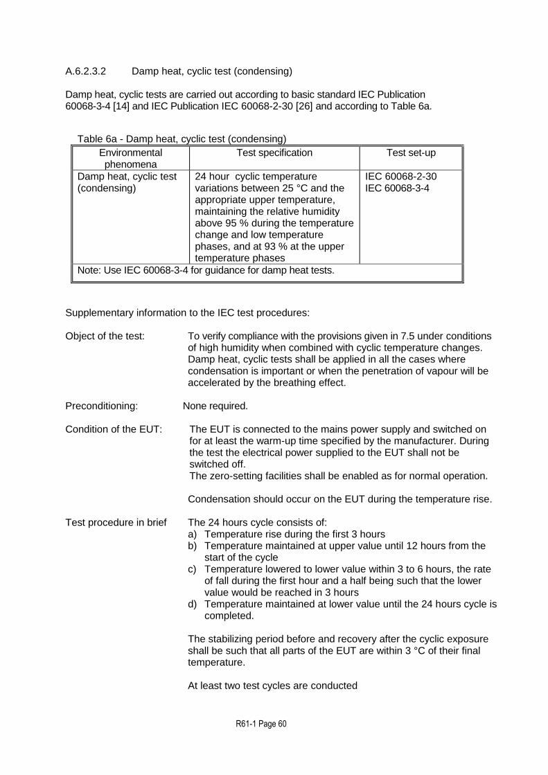
R61-1 Page 60
A.6.2.3.2 Damp heat, cyclic test (condensing) Damp heat, cyclic tests are carried out according to basic standard IEC Publication 60068-3-4 [14] and IEC Publication IEC 60068-2-30 [26] and according to Table 6a.
Table 6a - Damp heat, cyclic test (condensing)
Environmental phenomena
Test specification Test set-up
Damp heat, cyclic test (condensing)
24 hour cyclic temperature variations between 25 °C and the appropriate upper temperature, maintaining the relative humidity above 95 % during the temperature change and low temperature phases, and at 93 % at the upper temperature phases
IEC 60068-2-30 IEC 60068-3-4
Note: Use IEC 60068-3-4 for guidance for damp heat tests.
Supplementary information to the IEC test procedures: Object of the test: To verify compliance with the provisions given in 7.5 under conditions
of high humidity when combined with cyclic temperature changes. Damp heat, cyclic tests shall be applied in all the cases where condensation is important or when the penetration of vapour will be accelerated by the breathing effect.
Preconditioning: NNone required.
Condition of the EUT: The EUT is connected to the mains power supply and switched on
for at least the warm-up time specified by the manufacturer. During the test the electrical power supplied to the EUT shall not be switched off. The zero-setting facilities shall be enabled as for normal operation. Condensation should occur on the EUT during the temperature rise.
Test procedure in brief The 24 hours cycle consists of: a) Temperature rise during the first 3 hours b) Temperature maintained at upper value until 12 hours from the
start of the cycle c) Temperature lowered to lower value within 3 to 6 hours, the rate
of fall during the first hour and a half being such that the lower value would be reached in 3 hours
d) Temperature maintained at lower value until the 24 hours cycle is completed.
The stabilizing period before and recovery after the cyclic exposure shall be such that all parts of the EUT are within 3 °C of their final temperature.
At least two test cycles are conducted

R61-1 Page 61
Test information: After stabilisation of the EUT at reference temperature and 50 % humidity apply the test load. Record:
a) date and time; b) temperature; c) relative humidity; d) test load; e) indications (as applicable); f) errors; g) functional performance h) barometric pressure.
Repeat the above for the second test cycle. Allow full recovery of the EUT before any other tests are performed.
Maximum allowable variations:
All functions shall operate as designed. All errors shall be within the maximum permissible errors specified in 4.2.2.
A.6.2.4 AC mains voltage variation (in accordance with 4.7.2) AC mains voltage variation tests are carried out according to basic standard IEC/TR Publication 61000-2-1 [15] and IEC Publication 61000-4-1[16],and according to Table 7.
Table 7 - AC mains voltage variation tests
Environmental
Phenomena
Test specification Test set-up
AC mains voltage variation
Unom
IEC 61000-2-1 IEC 61000-4-1
Upper limit: 110 % of Unom or Umax
Lower limit: 85 % of Unom or Umin
Unom
NOTE: Where an instrument is powered by a three phase supply, the voltage variations shall apply for each phase successively.
Supplementary information to the IEC test procedures: Object of the test: To verify compliance with the provisions given in 4.7.2
under conditions of voltage variations.
Condition of the EUT: The EUT is connected to the mains power supply and switched on for at least the warm-up time specified by the manufacturer. During the test the electrical power supplied to the EUT shall not be switched off. Adjust the EUT as close to zero indication as practicable, prior to the test. If it has an automatic zero-setting function then the instrument should be set to zero after applying each level of voltage.

R61-1 Page 62
Number of test cycles: At least one cycle.
Weighing test: The EUT shall be tested with a test load approximately equal to the minimum capacity, and one load between ½ Max and Max. Zero-setting function shall be in operation.
Test sequence: Stabilize the power supply voltage at the nominal voltage within the defined limits and apply the test load. Record the following data:
a) Date and time b) Temperature c) Voltage supply d) Test load e) Indications (as applicable) f) Errors g) Functional performance
Repeat the test weighing for each of the voltages defined in IEC 61000-4-1[16] in section 5 (noting the need in certain cases to repeat the test weighing at both ends of the voltage range) and record the indications.
Maximum allowable variations: All functions shall operate as designed. All errors shall be within the maximum permissible errors specified in 4.2.2.
A.6.2.5 DC mains voltage variation (4.7.2)
AGFIs operating from DC mains power supply shall fulfil the tests in A.6.2, with the exception of A.6.2.4 which is to be replaced by the test according to basic standard IEC Publication 60654-2 [17] and according to Table 8.
Table 8 – DC mains voltage variation test
Environmental phenomena
Test specification Test set-up
DC mains voltage variations
Unom
IEC 60654-2
Upper limit: DC level at which the EUT has been manufactured to automatically detect high-level conditions
Lower limit: Minimum operating that automatically detect low-level conditions
Unom
NOTE: If a voltage-range is marked, use the average value as the nominal voltage, Unom.
Supplementary information to the IEC test procedures:
Object of the test: To verify compliance with the provisions in 4.7.2 under
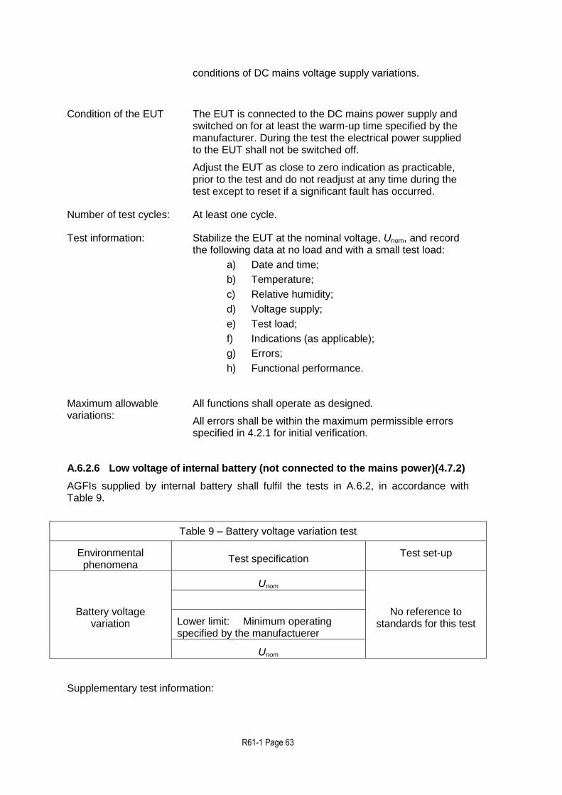
R61-1 Page 63
conditions of DC mains voltage supply variations.
Condition of the EUT The EUT is connected to the DC mains power supply and switched on for at least the warm-up time specified by the manufacturer. During the test the electrical power supplied to the EUT shall not be switched off.
Adjust the EUT as close to zero indication as practicable, prior to the test and do not readjust at any time during the test except to reset if a significant fault has occurred.
Number of test cycles: At least one cycle.
Test information: Stabilize the EUT at the nominal voltage, Unom, and record the following data at no load and with a small test load:
a) Date and time;
b) Temperature;
c) Relative humidity;
d) Voltage supply;
e) Test load;
f) Indications (as applicable);
g) Errors;
h) Functional performance.
Maximum allowable variations:
All functions shall operate as designed.
All errors shall be within the maximum permissible errors specified in 4.2.1 for initial verification.
A.6.2.6 Low voltage of internal battery (not connected to the mains power)(4.7.2)
AGFIs supplied by internal battery shall fulfil the tests in A.6.2, in accordance with Table 9.
Table 9 – Battery voltage variation test
Environmental phenomena
Test specification Test set-up
Battery voltage variation
Unom
No reference to standards for this test
Lower limit: Minimum operating specified by the manufactuerer
Unom
Supplementary test information:

R61-1 Page 64
Object of the test: To verify compliance with the provisions in 4.7.2 under conditions of battery voltage variations.
Condition of the EUT The EUT is connected to the battery voltage supply, fully charged or at the maximum voltage as specified by the manufacturer and switched on for at least the warm-up time specified by the manufacturer. During the test the electrical power supplied to the EUT shall not be switched off.
Adjust the EUT as close to zero indication as practicable, prior to the test and do not readjust at any time during the test except to reset if a significant fault has occurred.
Number of test cycles: At least one cycle.
Test information: Stabilize the EUT at the nominal voltage, Unom, and record the following data at no load and with a small test load:
a) Date and time; b) Temperature; c) Relative humidity; d) Voltage supply; e) Test load; f) Indications (as applicable); g) Errors; h) Functional performance.
Reduce the voltage of the battery until the instrument:
a) automatically resumes normal operation producing a clear warning
b) ceases to function properly
Record the indications and response of the instrument just before and after it responds to the low voltage condition.
Maximum allowable variations:
For voltages above the lower limit, all functions shall operate as designed; for voltages below the lower limit, the instrument shall automatically resume normal operation without loss of any previous measurement data.
All errors shall be within the maximum permissible errors specified in 4.2.1 for initial verification.
A.6.2.7 Power from external 12V and 24V road vehicle batteries (4.7.2)
Road vehicle battery operated instruments shall fulfil the tests in A.6.2, with the exception of A.6.2.4 which is to be replaced by the following test conducted in accordance with ISO 16750-2 [27] and according to Table 10.
Table 10 – Voltage variation from 12 V and 24 V road vehicle batteries
Environmental phenomena
Test specification Test set-up
Unom Upper limit Lower limit
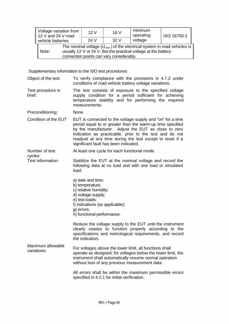
R61-1 Page 65
Voltage variation from 12 V and 24 V road vehicle batteries
12 V 16 V minimum operating voltage
ISO 16750-2 24 V 32 V
Note: The nominal voltage (Unom ) of the electrical system in road vehicles is usually 12 V or 24 V. But the practical voltage at the battery-connection points can vary considerably.
Supplementary information to the ISO test procedures:
Object of the test: To verify compliance with the provisions in 4.7.2 under conditions of road vehicle battery voltage variations.
Test procedure in brief:
The test consists of exposure to the specified voltage supply condition for a period sufficient for achieving temperature stability and for performing the required measurements.
Preconditioning: None
Condition of the EUT EUT is connected to the voltage supply and "on" for a time period equal to or greater than the warm-up time specified by the manufacturer. Adjust the EUT as close to zero indication as practicable, prior to the test and do not readjust at any time during the test except to reset if a significant fault has been indicated.
Number of test cycles:
At least one cycle for each functional mode.
Test information: Stabilize the EUT at the nominal voltage and record the following data at no load and with one load or simulated load: a) date and time; b) temperature; c) relative humidity; d) voltage supply; e) test loads; f) indications (as applicable); g) errors; h) functional performance. Reduce the voltage supply to the EUT until the instrument clearly ceases to function properly according to the specifications and metrological requirements, and record the indication.
Maximum allowable variations:
For voltages above the lower limit, all functions shall operate as designed; for voltages below the lower limit, the instrument shall automatically resume normal operation without loss of any previous measurement data. All errors shall be within the maximum permissible errors specified in 4.2.1 for initial verification.

R61-1 Page 66
A.6.2.8 Tilting (4.7.3)
A.6.2.8.1 Tilting of AFGIs fitted with a level indicator or automatic tilt sensor (4.7.3 a and b)
A.6.2.8.1.1 Tilting at no-load
The AFGI shall be set to zero in its reference position (not tilted). The AFGI shall then be tilted longitudinally up to the limiting value of tilting. The zero indication is noted. The test shall be repeated with transverse tilting.
A.6.2.8.2 Tilting when loaded
The AFGI shall be set to zero in its reference position and two weighings shall be carried out at a load close to the lowest load where the maximum permissible error changes, and at a load close to Max. The AFGIs is then unloaded and tilted longitudinally and set to zero. The tilting shall be equal to the limiting value of tilting. Weighing tests as described above shall be performed. The test shall be repeated with transverse tilting.
A.6.2.8.3 AFGIs not fitted with a level indicator or an automatic tilt sensor (4.7.3 c)
The test in A.6.2.8.3 only applies for AFGIs liable to be tilted and not fitted with a level indicator which clearly indicates when the maximum permissible tilt has been exceeded nor with an automatic tilt sensor which clearly indicates when the maximum permissible tilt has been exceeded (e.g. by producing an error code or signal) and inhibits any printout and transmission of measurement data. Object of the test: To verify compliance with the provisions given in
4.7.3.
Test procedure in brief: The test consist of tilting the EUT both forwards and backwards, longitudinally and from side to side (transversely), while observing the weight indications for a static test load.
Test severity: Two test loads at Min and Max at a tilt of 5%
Maximum allowable variations: All indications shall be within maximum permissible errors specified in 4.2.2.
Condition of EUT: The EUT is switched on for at least the warm-up time specified by the manufacturer. During the test the electrical power supplied to the EUT shall not be switched off.
Adjust the EUT in its reference position (not tilted) as close to zero indication as practicable. If the instrument is provided with automatic zero-setting it shall not be in operation.
Test sequence: Record the zero indication. Apply the test load approximately equal to the Max and record the indication. Remove the test load.
Tilt the EUT longitudinally to the appropriate extent and record the zero indication. Apply the test load

R61-1 Page 67
approximately equal to the Max and record the indication. Remove the test load.
Without further adjustment to any control affecting metrological performance tilt the EUT to the appropriate extent in the opposite direction and repeat the static weighing tests as above.
Tilt the EUT in the transverse direction to the appropriate extent and repeat the above tests.
Tilt the EUT in the opposite direction and repeat the above tests.
Record the following data for each of the test set-ups as prescribed above: a) Date and time b) Test load c) Indications at each tilt d) Errors e) Functional performance
In order to determine the influence of tilting on the loaded instrument, the indication obtained at each tilt shall be corrected for the deviation from zero which the instrument had prior to loading.
A.6.3 Disturbance tests (in accordance with 7.2)
Summary of disturbance tests
§ Test Condition applied
A.6.3.1 AC mains voltage dips, short interruptions and reductions
Significant fault
A.6.3.2 Bursts (fast transient tests) on mains power lines and on signal, data and control lines
Significant fault
A.6.3.3 Electrostatic discharge Significant fault
A.6.3.4 Immunity to electromagnetic fields Significant fault
A.6.3.5 Surges on AC and DC mains power lines and on signal, data and control lines
Significant fault
NOTE 1: Tests shall be conducted to the appropriate classification for electrical tests. The severity level stated in the tests A.6.3.1 to A.6.3.5 apply to AGFIs installed and used in locations with significant or high levels of electromagnetic disturbances corresponding to those likely to be found in industrial environments, class E2 of OIML D11 [4].
NOTE 2: If there are interfaces on the instrument (or simulator), the use of these interfaces to other equipment shall be simulated in the tests. For this purpose, either an appropriate peripheral device or 3 m of interface cable to simulate the interface impedance of the other equipment shall be connected to each different type of interface.
A.6.3.1 AC mains voltage dips, short interruptions and reductions

R61-1 Page 68
AC mains voltage dips and short interruptions tests are carried out according to basic standard IEC Publication 61000-4-11[18], and according to Table 11.
Table 11 - AC mains voltage dips and short interruptions
Environmental phenomena
Test specification Test set-
up
Test Reduction of amplitude to
Duration / Number of
cycles
IEC 61000-4-
11 Voltage dips and short interruptions
Test a 0 % 0.5
Test b 0 % 1
Test c 40 % 10/122
Test d 70 % 25/302
Test e 80 % 250/3002
Short interruption
0 % 250/3002
NOTE 1: A test generator suitable to reduce for a defined period of time the amplitude of one or more half cycles (at zero crossings) of the AC mains voltage shall be used. The test generator shall be adjusted before connecting the EUT. The mains voltage reductions shall be repeated ten times with an interval of at least ten seconds.
NOTE 2: These values are depending on national AC mains frequency
NOTE 3: In case of transient faults due transient disturbances it shall be considered whether these could make the AGFI detect that the preset value of the fill is reached. To that end the preset value of the fill may be set to a value that exceeds the test load by exactly the significant fault. In case of exceeding the significant fault the AGFI would signal that the preset value has been reached by e.g. setting a digital output. Thus a significant fault due to transient disturbances can be detected.
Supplementary information to the IEC test procedures:
Object of the test: To verify compliance with the provisions given in 7.2 under conditions of short mains voltage interruptions and reductions while observing the weight indication for a small static load.
Test procedure in brief:
Condition of the EUT: The EUT is connected to the mains power supply and switched on for at least the warm-up time specified by the manufacturer. During the test the electrical power supplied to the EUT shall not be switched off.
Adjust the EUT as close to zero indication as

R61-1 Page 69
practicable, prior to the test. Zero-setting functions shall not be in operation. Not to be adjusted or readjusted at any time during the test except the reset if a significant fault has been indicated.
Number of test cycles: At least one cycle.
Weighing test: The EUT shall be tested with a small static test load.
Stabilize all factors at nominal reference conditions. Apply the test load and record the following data:
a) Date and time b) Temperature c) Relative humidity; d) Voltage supply e) Test load f) Indications g) Errors h) Functional performance
Interrupt the power supply voltage to zero voltage for a period equal to one half cycle and conduct the test as detailed in IEC 61000-4-11[18] section 8.2.1. During interruption observe the effect on the EUT and record as appropriate. Reduce the voltage supply to 50 % of nominal voltage for a period equal to two half cycles and conduct the test as detailed in IEC 61000-4-11 section 8.2.1 during reductions observe the effect on the EUT and record, as appropriate.
Maximum allowable variations: The difference between the weight indication due to the disturbance and the indication without the disturbance either shall not exceed the significant fault value specified in 0.5.2.6, or the EUT shall detect and act upon a significant fault.
A.6.3.2 Bursts (fast transient tests) on mains power lines and on signal, data and
control Electrical bursts tests (fast transient tests) are carried out according to basic standard IEC 61000-4-4[19] for 2 minutes with a positive polarity and for 2 minutes with a negative polarity, and according to Table 11.1 and Table 12.2.
Table 12.1: Bursts (transients) on on signal, data and control lines
Environmental phenomena Test specification Test set-up
Fast transient common mode 1.0 kV (peak) 5/50 ns T1 / Th 5 kHz rep. Frequency
IEC 61000-4-4
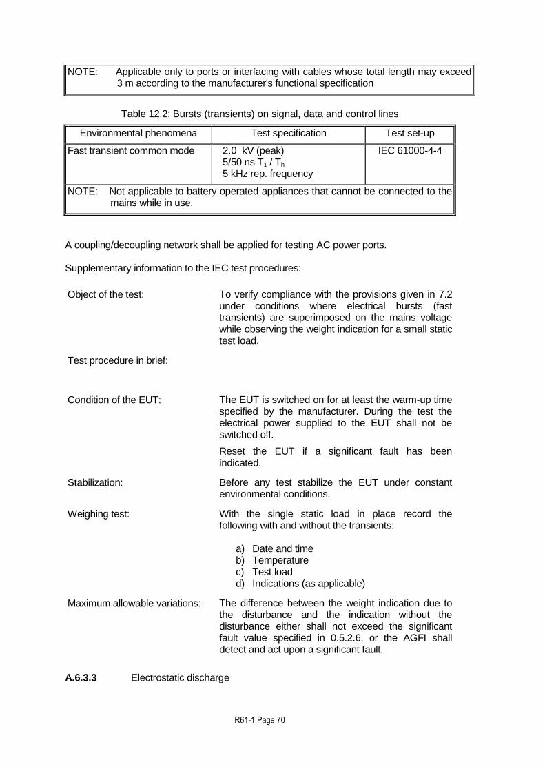
R61-1 Page 70
NOTE: Applicable only to ports or interfacing with cables whose total length may exceed 3 m according to the manufacturer's functional specification
Table 12.2: Bursts (transients) on signal, data and control lines
Environmental phenomena Test specification Test set-up
Fast transient common mode 2.0 kV (peak) 5/50 ns T1 / Th 5 kHz rep. frequency
IEC 61000-4-4
NOTE: Not applicable to battery operated appliances that cannot be connected to the mains while in use.
A coupling/decoupling network shall be applied for testing AC power ports. Supplementary information to the IEC test procedures:
Object of the test: To verify compliance with the provisions given in 7.2 under conditions where electrical bursts (fast transients) are superimposed on the mains voltage while observing the weight indication for a small static test load.
Test procedure in brief:
Condition of the EUT: The EUT is switched on for at least the warm-up time specified by the manufacturer. During the test the electrical power supplied to the EUT shall not be switched off.
Reset the EUT if a significant fault has been indicated.
Stabilization: Before any test stabilize the EUT under constant environmental conditions.
Weighing test: With the single static load in place record the following with and without the transients:
a) Date and time b) Temperature c) Test load d) Indications (as applicable)
Maximum allowable variations: The difference between the weight indication due to the disturbance and the indication without the disturbance either shall not exceed the significant fault value specified in 0.5.2.6, or the AGFI shall detect and act upon a significant fault.
A.6.3.3 Electrostatic discharge

R61-1 Page 71
Electrostatic discharge tests are carried out according to basic standard IEC 61000-4-2 [21], with test signals and conditions as given in Table 13.
Table 13 – Electrostatic discharge tests
Environmental phenomena Test specification Test set-up
Electrostatic discharge 8 kV air discharge 6 kV contact discharge
IEC 61000-4-2
NOTE 1: Tests shall be performed at the specified lower levels, starting with 2 kV and proceeding with 2 kV steps up to and including the level specified above in accordance with IEC 61000-4-2.
NOTE 2: The 6 kV contact discharge shall be applied to conductive accessible parts. Metallic contacts, e.g. in battery compartments or in socket outlets are excluded from this requirement.
Contact discharge is the preferred test method. 20 discharges (10 with positive and 10 with negative polarity) shall be applied on each accessible metal part of the enclosure. The time interval between successive discharges shall be at least 10 s. In the case of a non conductive enclosure, discharges shall be applied on the horizontal or vertical coupling planes as specified in IEC 61000-4-2 [21]. Air discharges shall be used where contact discharges cannot be applied. Tests with other (lower) voltages than those given in Table 13 are not required. Supplementary information to the IEC test procedures: Object of the test: To verify compliance with the provisions given in 7.2
under conditions where electrostatic discharges are applied while observing the weight indication for a small static test load.
Test procedure in brief:
Condition of the EUT: The EUT is connected to the voltage supply and switched on for at least the warm-up time specified by the manufacturer. During the test the electrical power supplied to the EUT shall not be switched off.
Reset the EUT if a significant fault has been indicated.
Stabilization: Before any test stabilize the EUT under constant environmental conditions.
Weighing test: With the single static load in place, record the following with and without electrostatic discharge:
a) Date and time b) Temperature c) Test load d) Indications (as applicable)
Maximum allowable variations: The difference between the weight indication due to the disturbance and the indication without the disturbance either shall not exceed the significant fault value specified in 0.5.2.6, or the AGFI shall

R61-1 Page 72
detect and act upon a significant fault.
A.6.3.4 Immunity to electromagnetic fields
A.6.3.4.1 Immunity to radiated (RF) electromagnetic fields Radiated, radio frequency electromagnetic immunity tests are carried out to IEC 61000-4-3 [22], and according to Table 14. The unmodulated carrier of the test signal is adjusted to the indicated test value. To perform the test, the carrier is in addition modulated as specified.
Table 14 - Immunity to radiated (RF) electromagnetic fields
Test specification
Environmental phenomena
Frequency ranges (MHz)
Field strength (V/m)
Test set-up
Radiated electromagnetic immunity tests
80 to 2700(1)
10 IEC 61000-4-3 26 to 80(2)
Modulation 80 % AM, 1 kHz sine wave
NOTE 1: To use anechoic room method like specified in IEC 61000-4-3 [22] the frequency range is only applied above 80 MHz. For the lower frequency range the test methods for conducted radio frequency disturbances (A.6.3.4.2) are recommended.
NOTE 2: For EUT lacking any cabling as is needed for applying the test specified in Table 15 the lower frequency limit shall be 26 MHz (refer to Annex F of IEC 61000-4-3 [22]). In all other cases both tests presented in Table 14 and Table15 apply..
Supplementary information to the IEC test procedures:
Object of the test: To verify compliance with the provisions given in 7.2 under conditions of specified electromagnetic fields applied while observing the weight indication for a small static test load.
Test procedure in brief:
Condition of the EUT: The EUT is connected to the voltage supply and switched on for at least the warm-up time specified by the manufacturer. During the test the electrical power supplied to the EUT shall not be switched off.
Reset the EUT if a significant fault has been indicated.
Stabilization: Before any test stabilize the EUT under constant environmental conditions.

R61-1 Page 73
Weighing test: With the single static load in place record the following with and without electromagnetic fields:
a) Date and time b) Temperature c) Test load d) Indications (as applicable)
Maximum allowable variations: The difference between the weight indication due to the disturbance and the indication without the disturbance either shall not exceed the significant fault value in 0.5.2.6, or the AGFI shall detect and act upon a significant fault.
A.6.3.4.2 Immunity to conducted electromagnetic fields Conducted, radio frequency, electromagnetic field immunity tests are carried out in accordance to IEC 61000-4-6[23] and according to Table 15.
The unmodulated carrier of the test signal is adjusted to the indicated test value. To perform the test the carrier is in addition modulated as specified.
Table 15 – Immunity to conducted electromagnetic fields
Test specification
Environmental phenomena
Frequency range
MHz
RF amplitude (50 ohms)
V (e.m.f) Test set-up
Conducted electromagnetic immunity tests
0.15 to 80 10 IEC 61000-4-6
Modulation 80 % AM, 1 kHz sine wave
NOTE: This test is not applicable when the EUT has no mains or other input port.
Coupling and decoupling devices shall be used for appropriate coupling of the disturbing signal (over the entire frequency range, with defined common-mode impedance at the EUT port) to the various conducting cables connected to the EUT. Supplementary information to the IEC test procedures:
Object of the test: To verify compliance with the provisions given in 7.2 under conditions of specified conducted electromagnetic fields while observing the weight indication for a static test load.
Test procedure in brief:

R61-1 Page 74
Condition of the EUT: The EUT is connected to the voltage supply and switched on for at least the warm-up time specified by the manufacturer. During the test the electrical power supplied to the EUT shall not be switched off.
Reset the EUT if a significant fault has been indicated.
Stabilization: Before any test stabilize the EUT under constant environmental conditions.
Weighing test: With the single static load in place record the following with and without electromagnetic fields:
a) Date and time b) Temperature c) Test load d) Indications (as applicable)
Maximum allowable variations: The difference between the weight indication due to the disturbance and the indication without the disturbance either shall not exceed the significant fault value in 0.5.2.6, or the AGFI shall detect and act upon a significant fault.
A.6.3.5 Surges on AC and DC mains power lines and on signal, data and control lines Electrical surge tests are carried out according to IEC 61000-4-5 [20] and according to Table 16.
Table 16 - Surges on AC and DC mains power lines and on signal, data and control lines
Environmental phenomena
Test specification Test set-up
Surges on mains power lines and on signal and communication lines
a) 1.0 kV line to line b) 2.0 kV line to earth
c) 3 positive and 3 negative surges applied synchronously with AC supply voltage in angles 0°, 90°, 180° and 270°.
d) 3 positive and 3 negative surges applied on DC voltage lines and on signal and communication lines.
IEC 61000-4-5
Note:
This test is only applicable in those cases where, based on typical situations of installation, the risk of a significant influence of surges can be expected. This is especially relevant in cases of outdoor installations and/or indoor installations connected to long signal lines (lines longer than 30 m or those lines partially or fully installed outside the buildings regardless of their length).

R61-1 Page 75
Supplementary information to the IEC test procedures: Object of the test: To verify compliance with the provisions in 7.2 under
conditions where electrical surges are applied separately to the mains voltage lines and to the signal and communication lines (if any), while observing the weight indication for a small static test load.
Condition of the EUT: The characteristics of the test generator shall be verified before connecting the EUT. The EUT is connected to the power supply and switched on for at least the warm-up time specified by the manufacturer. During the test the electrical power supplied to the EUT shall not be switched off. Adjust the EUT as close to zero indication as practicable, prior to the test. Zero-setting functions shall not be in operation and are not to be adjusted at any time during the test except to re-set if a significant fault has occurred.
Number of test cycles: At least one cycle.
Test information: The test consists of exposure to surges for which the rise time, pulse width, peak values of the output voltage/current on high/low impendence load and minimum time interval between two successive pulses are defined in IEC 61000-4-5. The injection network depends on the lines the surge is coupled to and is defined in IEC 61000-4-5. Before any test stabilize the EUT under constant environmental conditions. Changes in barometric pressure shall be taken into account. With the single static load in place record the following with and without the surges:
a) Date and time; b) Temperature; c) Relative humidity; d) Supply voltage; e) Test load; f) Indications (as applicable); g) Errors; h) Functional performance; i) Barometric pressure
Maximum allowable variations:
The difference between the indication due to the disturbance and the indication without the disturbance (intrinsic error) either shall not exceed the fault specified in 0.5.2.6, or the EUT shall detect and react to a significant fault.
A.7 Span stability test (in accordance with 7.10.3)
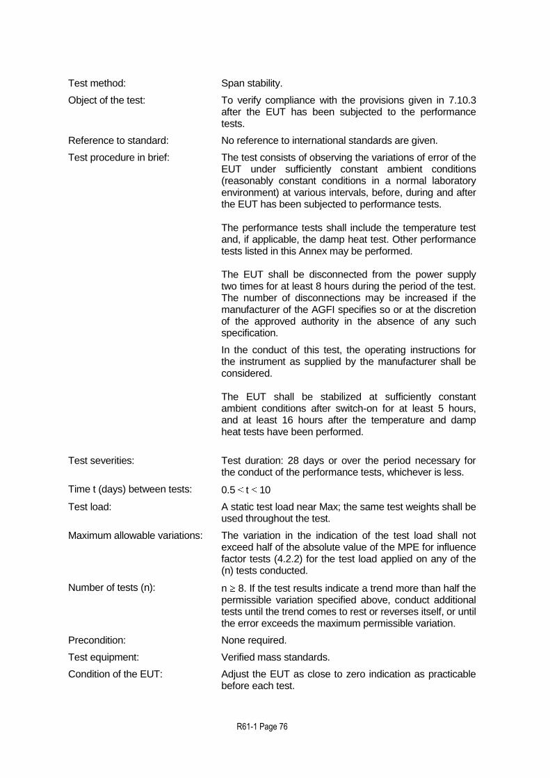
R61-1 Page 76
Test method: Span stability.
Object of the test: To verify compliance with the provisions given in 7.10.3 after the EUT has been subjected to the performance tests.
Reference to standard: No reference to international standards are given.
Test procedure in brief: The test consists of observing the variations of error of the EUT under sufficiently constant ambient conditions (reasonably constant conditions in a normal laboratory environment) at various intervals, before, during and after the EUT has been subjected to performance tests. The performance tests shall include the temperature test and, if applicable, the damp heat test. Other performance tests listed in this Annex may be performed. The EUT shall be disconnected from the power supply two times for at least 8 hours during the period of the test. The number of disconnections may be increased if the manufacturer of the AGFI specifies so or at the discretion of the approved authority in the absence of any such specification.
In the conduct of this test, the operating instructions for the instrument as supplied by the manufacturer shall be considered. The EUT shall be stabilized at sufficiently constant ambient conditions after switch-on for at least 5 hours, and at least 16 hours after the temperature and damp heat tests have been performed.
Test severities: Test duration: 28 days or over the period necessary for the conduct of the performance tests, whichever is less.
Time t (days) between tests: 0.5 t 10
Test load: A static test load near Max; the same test weights shall be used throughout the test.
Maximum allowable variations: The variation in the indication of the test load shall not exceed half of the absolute value of the MPE for influence factor tests (4.2.2) for the test load applied on any of the (n) tests conducted.
Number of tests (n): n 8. If the test results indicate a trend more than half the permissible variation specified above, conduct additional tests until the trend comes to rest or reverses itself, or until the error exceeds the maximum permissible variation.
Precondition: None required.
Test equipment: Verified mass standards.
Condition of the EUT: Adjust the EUT as close to zero indication as practicable before each test.
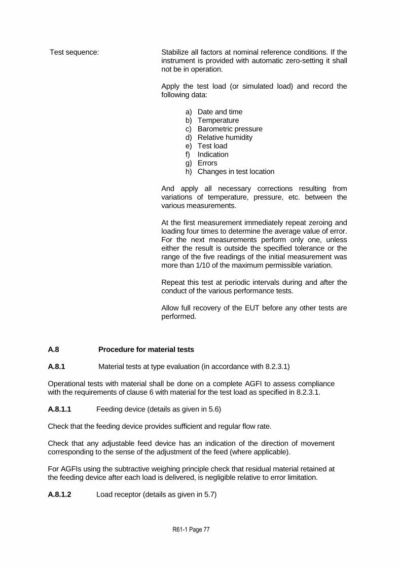
R61-1 Page 77
Test sequence: Stabilize all factors at nominal reference conditions. If the instrument is provided with automatic zero-setting it shall not be in operation. Apply the test load (or simulated load) and record the following data:
a) Date and time b) Temperature c) Barometric pressure d) Relative humidity e) Test load f) Indication g) Errors h) Changes in test location
And apply all necessary corrections resulting from variations of temperature, pressure, etc. between the various measurements. At the first measurement immediately repeat zeroing and loading four times to determine the average value of error. For the next measurements perform only one, unless either the result is outside the specified tolerance or the range of the five readings of the initial measurement was more than 1/10 of the maximum permissible variation. Repeat this test at periodic intervals during and after the conduct of the various performance tests. Allow full recovery of the EUT before any other tests are performed.
A.8 Procedure for material tests A.8.1 Material tests at type evaluation (in accordance with 8.2.3.1) Operational tests with material shall be done on a complete AGFI to assess compliance with the requirements of clause 6 with material for the test load as specified in 8.2.3.1.
A.8.1.1 Feeding device (details as given in 5.6) Check that the feeding device provides sufficient and regular flow rate. Check that any adjustable feed device has an indication of the direction of movement corresponding to the sense of the adjustment of the feed (where applicable). For AGFIs using the subtractive weighing principle check that residual material retained at the feeding device after each load is delivered, is negligible relative to error limitation. A.8.1.2 Load receptor (details as given in 5.7)
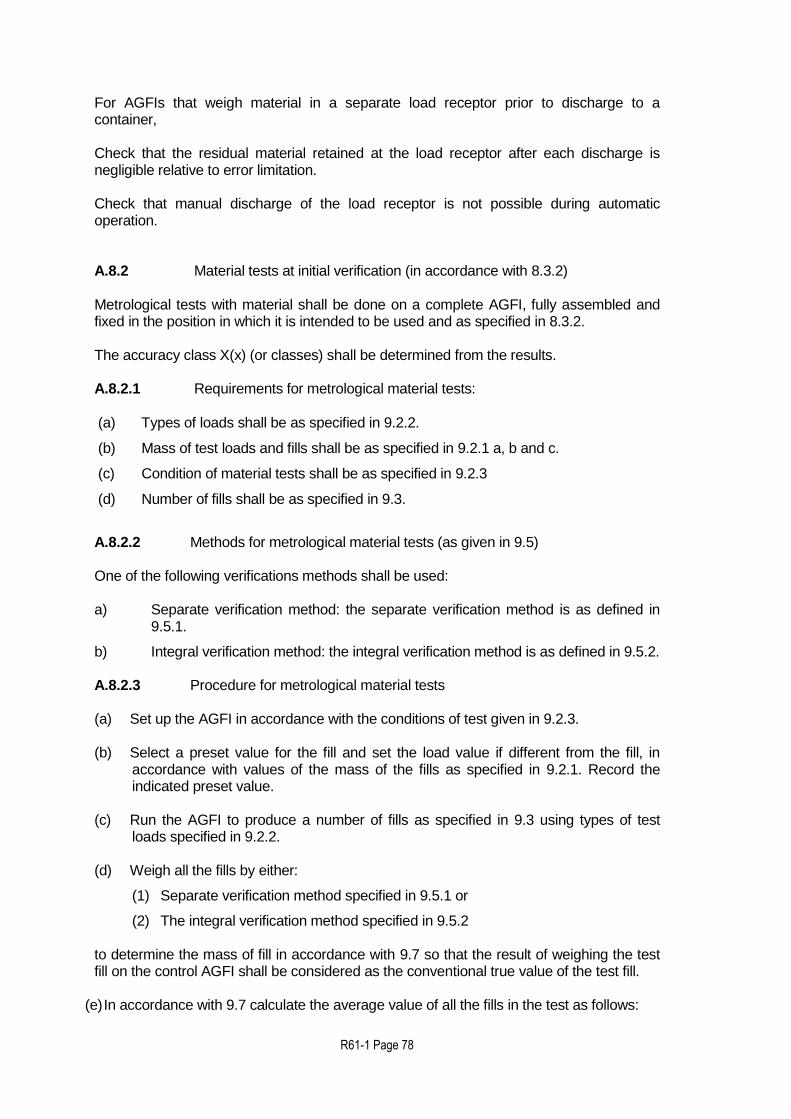
R61-1 Page 78
For AGFIs that weigh material in a separate load receptor prior to discharge to a container, Check that the residual material retained at the load receptor after each discharge is negligible relative to error limitation. Check that manual discharge of the load receptor is not possible during automatic operation. A.8.2 Material tests at initial verification (in accordance with 8.3.2) Metrological tests with material shall be done on a complete AGFI, fully assembled and fixed in the position in which it is intended to be used and as specified in 8.3.2. The accuracy class X(x) (or classes) shall be determined from the results. A.8.2.1 Requirements for metrological material tests: (a) Types of loads shall be as specified in 9.2.2. (b) Mass of test loads and fills shall be as specified in 9.2.1 a, b and c. (c) Condition of material tests shall be as specified in 9.2.3 (d) Number of fills shall be as specified in 9.3. A.8.2.2 Methods for metrological material tests (as given in 9.5) One of the following verifications methods shall be used:
a) Separate verification method: the separate verification method is as defined in
9.5.1.
b) Integral verification method: the integral verification method is as defined in 9.5.2. A.8.2.3 Procedure for metrological material tests (a) Set up the AGFI in accordance with the conditions of test given in 9.2.3. (b) Select a preset value for the fill and set the load value if different from the fill, in
accordance with values of the mass of the fills as specified in 9.2.1. Record the indicated preset value.
(c) Run the AGFI to produce a number of fills as specified in 9.3 using types of test
loads specified in 9.2.2. (d) Weigh all the fills by either:
(1) Separate verification method specified in 9.5.1 or (2) The integral verification method specified in 9.5.2
to determine the mass of fill in accordance with 9.7 so that the result of weighing the test fill on the control AGFI shall be considered as the conventional true value of the test fill.
(e) In accordance with 9.7 calculate the average value of all the fills in the test as follows:
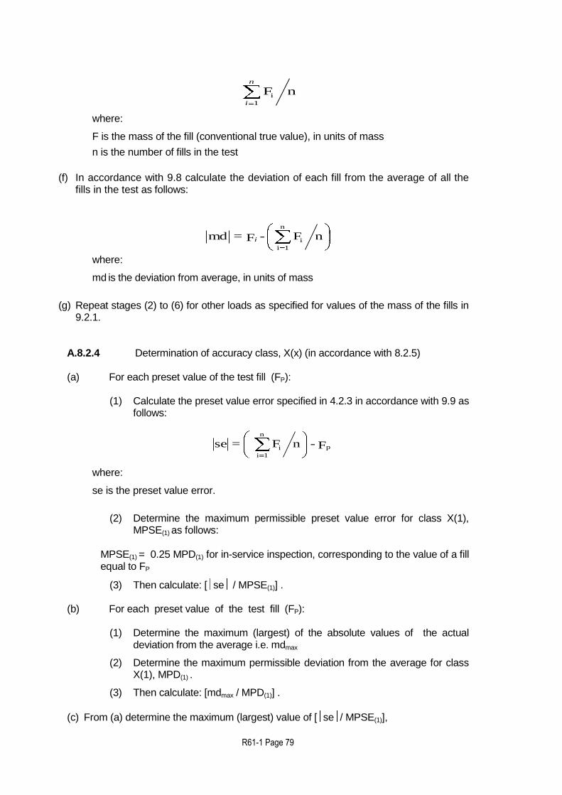
R61-1 Page 79
nF1
i
n
i
where: F is the mass of the fill (conventional true value), in units of mass
n is the number of fills in the test
(f) In accordance with 9.8 calculate the deviation of each fill from the average of all the fills in the test as follows:
where: md is the deviation from average, in units of mass
(g) Repeat stages (2) to (6) for other loads as specified for values of the mass of the fills in
9.2.1. A.8.2.4 Determination of accuracy class, X(x) (in accordance with 8.2.5)
(a) For each preset value of the test fill (FP):
(1) Calculate the preset value error specified in 4.2.3 in accordance with 9.9 as follows:
F - nF = se p
n
1i
i
where: se is the preset value error.
(2) Determine the maximum permissible preset value error for class X(1),
MPSE(1) as follows:
MPSE(1) = 0.25 MPD(1) for in-service inspection, corresponding to the value of a fill equal to FP
(3) Then calculate: [ se / MPSE(1)] .
(b) For each preset value of the test fill (FP):
(1) Determine the maximum (largest) of the absolute values of the actual deviation from the average i.e. mdmax
(2) Determine the maximum permissible deviation from the average for class
X(1), MPD(1) . (3) Then calculate: [mdmax / MPD(1)] .
(c) From (a) determine the maximum (largest) value of [ se / MPSE(1)],
nF-F= mdn
1i
ii

R61-1 Page 80
i.e. [ se / MPSE(1)]max from all the preset test fills (d) From (b) determine the maximum (largest) value of [mdmax / MPD(1)], i.e. [mdmax / MPD(1)]max from all the preset test fills (e) Determine the accuracy class (x) such that
(x) [ se / MPSE(1)]max
and (x) [mdmax/ MPD(1)]max
and (x) = 1 10k, 2 10k, or 5 10k, the index k being a positive or negative whole number or zero.

R61-1 Page 81
Annex B: Requirements for software controlled AGFIs (Mandatory)
The specific software terminology is defined in OIML D 31:2008 Chapter 3. B.1 General requirements B.1.1 Software identification The legally relevant parts of the software of a AGFI and/or its constituents shall be clearly identified with the software version or any other token. The identification may apply to more than one part but at least one part shall be dedicated to the legal purpose. The identification shall be inextricably linked to the software and shall be:
presented or printed on command, or
displayed during operation, or
displayed at switch-on for those AGFIs that can be switched on and off. If a constituent of the AGFI has no display, the identification shall be sent to some other device via a communication interface in order to be displayed on this device. As an exception, an imprint of the software identification on the AGFI shall be an acceptable solution if it satisfies the following three conditions:
a) The user interface does not have any control capability to activate the indication of the software identification on the display, or the display does not technically allow the identification of the software to be shown (analogue indicating device or electromechanical counter).
b) The AGFI does not have an interface to communicate the software identification.
c) After production of the AGFI a change of the software is not possible, or only possible if the hardware or a hardware component is also changed.
d) The software identification and the means of identification shall be stated in the type approval certificate.
B.1.2 Correctness of algorithms and functions The measuring algorithms and functions of the AGFI and/or its constituents shall be appropriate and functionally correct. It shall be possible to examine algorithms and functions either by metrological tests, software tests or software examination. B.1.3 Software protection (against fraud) The legally relevant software part shall be secured against unauthorized modification, loading, or changes by swapping the memory device. In addition to mechanical sealing, technical means may be necessary to protect AGFIs equipped with an operating system or an option to load software. Only clearly documented functions are allowed to be activated by the user interface, which shall be realized in such a way that it does not facilitate fraudulent use.

R61-1 Page 82
Parameters that fix the legally relevant characteristics of the AGFI shall be secured against unauthorized modification. For the purpose of verification, displaying of the current parameter settings shall be possible. Note: Device-specific parameters may be adjustable or selectable only in a special
operational mode of the AGFI. They may be classified as those that should be secured (unalterable) and those that may be accessed (alterable parameters) by an authorized person, e.g. the AGFI owner or product vendor.
Software protection comprises appropriate sealing by mechanical, electronic and/or cryptographic means, making an unauthorized intervention impossible or evident.
B.1.3.1 Support of fault detection The detection by the checking facilities of significant faults may be achieved by software. In such a case, this detecting software is considered legally relevant. The documentation to be submitted for type evaluation shall contain a list of the anomalies that might result in a significant fault but that will be detected by the software. The documentation shall include information on the expected reaction and in case needed for understanding its operation, a description of the detecting algorithm. B.2 Requirements for specific configurations B.2.1 Specifying and separating relevant parts and specifying interfaces
of parts Metrologically relevant parts of a AGFI – whether software or hardware parts – shall not be inadmissibly influenced by other parts of the AGFI. This requirement applies if the AGFI and/or its constituents have interfaces for communicating with other electronic devices, with the user, or with other software parts next to the metrological critical parts. B.2.1.1 Separation of constituents of an AGFI B.2.1.1.a Constituents of a AGFI that perform functions which are relevant to legal metrology shall be identified, clearly defined, and documented. These form the legally relevant part of the AGFI. B.2.1.1.b It shall be demonstrated that those relevant functions and data of constituents cannot be inadmissibly influenced by commands received via an interface. This implies that there is an unambiguous assignment of each command to all initiated functions or data changes in the constituent. B.2.1.2 Separation of software parts B.2.1.2.a All software modules (programs, subroutines, objects, etc.) that perform functions which are relevant to legal metrology or that contain legal metrology relevant data domains are considered to be legal metrology relevant software part of an AGFI. This part shall be made identifiable as described in B.1.1. If the separation of the software is not possible, all software is considered legally relevant.

R61-1 Page 83
B.2.1.2.b If the legal metrology relevant software part communicates with other software parts, a software interface shall be defined. All communication shall be performed exclusively via this interface. The legal metrology relevant software part and the interface shall be clearly documented. All legally relevant functions and data domains of the software shall be described to enable a type evaluation authority to decide whether this software is sufficiently separated. The interface comprises program code and dedicated data domains. Defined coded commands or data are to be exchanged between the software parts through storing to the dedicated data domain by one software part and reading from it by the other. Writing and reading program code is considered part of the software interface. The data domain forming the software interface shall be clearly defined and documented and include the code that exports from the legally relevant part to the interface and the code that imports from the interface to this legally relevant part. The declared software interface shall not be circumvented. The manufacturer is responsible for respecting these constraints. Technical means (such as sealing) of preventing a program from circumventing the interface or programming hidden commands shall not be possible. The programmer of the legal metrology relevant software part as well as the programmer of the legally non-relevant part shall be provided with instructions concerning these requirements by the manufacturer. B.2.1.2.c There shall be an unambiguous assignment of each command to all initiated functions or data changes in the legally relevant part of the software. Commands that communicate through the software interface shall be declared and documented. Only documented commands are allowed to be activated through the software interface. The manufacturer shall state the completeness of the documentation of commands. B.2.1.2.d Where legal metrology relevant software has been separated from non-relevant software, the legal metrology relevant software shall have priority using the resources over non-relevant software. The measurement task (realized by the legal metrology relevant software part) must not be delayed or blocked by other tasks. The manufacturer is responsible for respecting these constraints. Technical means for preventing a legally non-relevant program from disturbing legally relevant functions shall be provided. The programmer of the legally relevant software part as well as the programmer of the legal metrology non-relevant part shall be provided with instructions concerning these requirements by the manufacturer. B.2.2 Shared indications A display may be employed for presenting both information from the legal metrology relevant part of software and other information. Software that realizes the indication of measurement values and other legally relevant information belongs to the legally relevant part. B.2.3 Storage of data, transmission via communication systems If measurement values will be used at a location different from the place of measurement or at a stage later than the time of measurement, they may need to be

R61-1 Page 84
retrieved from the AGFI and be stored or transmitted in an insecure environment before they are used for legal purposes. In that case the following requirements apply: B.2.3.1 The measurement value stored or transmitted shall be accompanied by all relevant information necessary for the future legally relevant use. B.2.3.2 The data shall be protected by software means to guarantee the authenticity, integrity and, if necessary, the correctness of the information concerning the time of measurement. The software that displays or further processes the measurement values and the accompanying data shall check the time of measurement, authenticity, and integrity of the data after having read them from the insecure storage or after having received them from an insecure transmission channel. The memory device shall be fitted with a checking facility to ensure that if an irregularity is detected, the data shall be discarded or marked unusable. Software modules that prepare data for storing or sending, or that check data after reading or receiving are considered part of the legally relevant software. B.2.3.3 When transferring measurement values through an open network, it is necessary to apply cryptographic methods. Confidentiality key-codes employed for this purpose shall be kept secret and secured in the measuring AGFIs, electronic devices, or sub-assemblies involved. Security means shall be provided whereby these keys can only be input or read if a seal is broken. B.2.3.4 Transmission delay The measurement shall not be inadmissibly influenced by a transmission delay. B.2.3.5 Transmission interruption If communication network services become unavailable, no measurement data shall be lost. The loss of measurement data shall be prevented. B.2.4 Automatic storage When, considering the application, data storage is required, measurement data must be stored automatically, B.e. when the final value used for the legal purpose has been generated. The storage device must have sufficient permanency to ensure that the data are not corrupted under normal storage conditions. There shall be sufficient memory storage for any particular application. When the final value used for the legal purpose results from a calculation, all data that are necessary for the calculation must be automatically stored with the final value. B.2.5 Deleting of data Stored data may be deleted when the transaction is settled. Only after this condition is met and insufficient memory capacity is available for storage of successive data, it is permitted to delete memorized data when both the following conditions are met:

R61-1 Page 85
the sequence of deletion of data will be in the same order as the recording order (fifo) while the rules established for the particular application are respected;
the required deletion will start either automatically or after a specific manual operation.
B.3 Maintenance and re-configuration
Updating the legally relevant software of a instrument in service shall be considered as:
a modification of the instrument, when exchanging the software with another approved version;
a repair of the instrument, when re-installing the same version. An instrument which has been modified or repaired while in service may require initial or subsequent verification, dependant on national regulations. This clause does not concern software which has or will have no influence on metrological relevant functions or functioning of the instrument.
Annex C (Informative)
Equipment Under Test C.1 Selection of EUTs AGFIs shall be categorized primarily by the fundamental engineering design they are constructed upon. The categories of design may include but are not limited to the following basic operating principles:
Mechanical – no electronics;
Analogue, strain gauge type load cells;
Digital load cells. Those AGFIs using load cell technology may further be categorized by using the method that the load cells are mounted / connected to the weight receiving element and supporting structures. Examples may include but are not limited to:
Direct mounting of load cells without check rods;
Connection of the weighing elements to load cell via lever system;
Isolated from load cell and with check rods or flexures. The selection of EUTs to be tested shall be such that at least the EUT that represents the “worst case” sample from that family is selected along with a EUT representing a best (or better) casefrom the family. , It is recommended that the worst case EUT be selected based on the following:

R61-1 Page 86
For testing performed in a laboratory setting:
Lowest input signal from the force transducer(s);
Unit with all the interfaces (i.e. peripheral equipment, hardware components);
Unit with all the necessary load cells.
C.2 Other metrological features to be considered For example, it is not acceptable to test the temperature effect on no-load indication on one EUT and the combined effect on a different one. Variations in metrologically relevant features and functions such as different:
housings;
load receptors;
temperature and humidity ranges;
AGFI functions;
displacement transducer;
indications; etc.; may require additional partial testing of those factors which are influenced by that feature. These additional tests should preferably be carried out on the same EUT, but if this is not possible, tests on one or more additional EUTs may be performed under the responsibility of the testing authority. The ability of the AGFI to withstand all required performance tests during the evaluation may be a good indication of the durability.
Annex D (Informative) Considerations concerning durability
D.1 Type Approval A durability assessment performed under type evaluation should take into account that (lack of) durability may be a characteristic of a particular installation. Hence a decision not to type approve an AGFI may only be justified where the unacceptable level of durability is clearly a characteristic of the type. Where measures to ensure durability are taken, this shall be recorded in R60-3 Test Report format. D.2 Subsequent metrological control To reduce the risks of non-durable AGFIs the arrangements for subsequent metrological control shall incorporate means for reviewing intervals for subsequent verification and in-service inspection, based on performance of an AGFI over time. ILAC-G24/OIML D 10 [25] indicates methods (see clause 3) which are useful for this purpose.”

R61-1 Page 87
Should an AGFI (installed in a particular location) be found to be of unacceptable durability, that AGFI shall be withdrawn from use. If unacceptable durability was found to be a characteristic of the type (unacceptable durability regardless of the installation), withdrawal of the type approval shall be considered.
Annex E - Informative annex – considerations on MinFill
The value of Minfill relates to a number of requirements. These requirements are:
Temperature effect on no load indication (4.8.1.3)
Zero-setting accuracy (5.8.2)
Disturbances (7.2 if applicable)
Warm-up time (7.8 if applicable) The value as defined by the manufacturer shall be confirmed, using the results of the corresponding test procedures. If all required criteria are met and the zero-setting accuracy is 0.25 d this leads to:
0.25 d 0.25 MPD in-service * Minfill,
or Minfill d / MPD in-service For class X(x) AGFIs the minimum permissible values of Minfill for d values are:
Table E.1 Minimum permissible value of Minfill (g)
d (g)
X(0.2) X(0.5) X(1) X(2)
0.5 28 11 6 3
1 111 22 11 6
2 334 44 22 12
5 1665 335 110 30
10 3330 1330 330 110
20 6660 2660 1340 340
50 25000 6650 3350 1650
100 50000 20000 6700 3300
200 100000 40000 20000 6600
500 500 d 200 d 100d 50 d
Notes:
a) These values are given as a theoretical basis and for a given AGFI on a site are dependent on the products, conditions of use and whether operational tests have demonstrated that the tolerances have been met for this value
b) The gramme values are rounded to the d-values which can be
indicated
For calculating the Minfill value for class X(x) AGFIs the MPD and F values (masses of the fills in Table 1) are applied. Example 1:
R61-1 Page 88
Class X(0.2) AGFI d = 20 g and Estimated MPD (3% * 0.2) = 0.6% Combining the estimated MPD percentage and the value of d results in an absolute value of Minfill of: 20 g / 0.006 = 3330 g; This value is in the F range having an MPDin-service of 1.5% times the class; resulting in 0.3% relative to Fill, which is less than the 0.6 %. therefore further calculation is necessary as follows: Applying the 0,3 % the resulting Minfill value will be: 20 g / 0.003 = 6660 g, which value is correct while F range and MPD are coherent. Not for each absolute values of the MPD a Minfill can be obtained. Only the relative MPD values can be used for the calculation of the Minfill and the calculated Minfill shall be in the same (F) range as the MPD used in the calculation.
Example 2: Class X(1) AGFI d = 10 g Estimated Minfill 250 g From Table 1 a F of 250 g results in the constant value for MPD = 9 g. which implies 9 g = 3.6% for the estimated Minfill of 250 g. Based on the d value (10 g) and using this MPD percentage the Minfill would be: 10 g / 0.036 = 280 g: but for 280 g the MPD = 3.2% therefore further calculation(iteration) is necessary; using the last percentage the resulting Minfill value will be: 10 g / 0.032 = 310 g; but for 310 g the MPD = 3.0% ;therefore further calculation is necessary; using the last percentage the resulting Minfill alue will be: 10 g / 0.03 = 330 g; which value is correct because the F range and MPD are coherent.
Annex F - Error calculation for multi-load AGFIs
F.1 Significant fault for multi-load AGFIs a) Significant fault for selective combination weighers:
A fault greater than 0.25 MPD of each fill (as given in Table 1) for in-service inspection divided by the square root of the average (or optimum) number of loads in a fill, for a fill equal to the Min multiplied by the average (or optimum) number of loads in a fill. Example: For a class X(1) AGFI with Min = 200 g designed for an average of 8 loads per fill, fill = 1 600 g, the MPD of each fill from the average fill (as specified in Table 1) for in-service inspection is 1.5 % = 24 g. Hence the value of significant fault is:
0.25 (24 / 8) = 2.12 g b) Significant fault for cumulative weighers:
R61-1 Page 89
A fault greater than 0.25 MPD of each fill (as given in Table 1) for in-service inspection, for a fill equal to the Minfill, divided by the square root of the minimum number of loads per fill. Example: For a class X(1) AGFI with Max = 1 200 g and Minfill of 8 kg: 8 kg/1.2 kg = 6.67; therefore the minimum number of loads per fill is 7. The MPD (as given in in Table 1) for the Minfill of 8 kg is 1.5 % or 120 g. Hence the value of significant fault is:
0.25 (120 / 7) = 11.34 g NOTE: This definition of significant fault for cumulative weighers does not include Min. A
cumulative weigher would normally be used at or near to Max. F.2 Influence factor tests MPEs for multi-load AGFIs This method determines the maximum permissible error for influence factor testing for a fill consisting of more than one static test load. a) For selective combination weighers the MPE for any static test load during influence
factor tests shall be 0.25 MPD for in-service inspection for the appropriate mass of the fill divided by the square root of the average (or optimum) number of loads per fill.
Example: Class X(1) selective combination weigher, where the average number of loads per fill is equal to 4. For a static test load = 100 g the appropriate mass of the fill will be 400 g for which the MPD for in-service inspection is 3 %, i.e. 12 g. Hence the MPE for influence factor tests is:
0.25 (12 g / 4) = 1.5 g b) For cumulative weighers the MPE for any static test load during influence factor tests
shall be 0.25 MPD for in-service inspection for the Minfill divided by the square root of the minimum number of loads per fill.
Example: For a class X(1) AGFI with Max = 1 200 g and Minfill of 8 kg: 8 kg/1.2 kg = 6.67; therefore the minimum number of loads per fill = 7. The MPD (as specified in Table 1) for the Minfill of 8 kg is 1.5 %, i.e. 120 g. Hence the MPE for influence factor tests is:
0.25 (120 / 7) = 11.34 g NOTE: For cumulative weighers the average number of loads per fill is not known.
Therefore it is not possible to define the maximum permissible error for influence factors in terms of average loads per fill and appropriate mass of the fill. The above definition is based on Max load and Minfill.

R61-1 Page 90
BIBLIOGRAPHY Below are references to Publications of the International Electrotechnical Commission (IEC), where mention is made in some of the tests in Annex A. Use these or the most recent issue of the publication valid at the time of testing the AGFI.
Ref. Standards and reference
documents Description
[1] International Vocabulary of Metrology -Basic and General Concepts and Associated Terms (VIM) (2012)
Vocabulary, prepared by a joint working group consisting of experts appointed by BIPM, IEC, IFCC, ISO, IUPAC, IUPAP and OIML
[2] International Vocabulary of Terms in Legal Metrology, BIML, Paris (2000)
Vocabulary including only the concepts used in the field of legal metrology. These concepts concern the activities of the legal metrology service, the relevant documents as well as other problems linked with this activity. Also included in this Vocabulary are certain concepts of a general character which have been drawn from the VIM
[3] OIML B 3:2011
OIML Certificate System for Measuring Instruments (formerly OIML P 1)
Provides rules for issuing, registering and using OIML Certificates of conformity
[4] OIML D 11:2004
General requirements for electronic measuring instruments
Contains general requirements for electronic measuring instruments
[5] OIML R 111:2004
Weights of classes E1, E2, F1, F2, M1, M1–2, M2, M2–3 and M3
Provides the principal physical characteristics and metrological requirements for weights used with and for the verification of weighing instruments and weights of a lower class
[6] OIML R 60:2000
Metrological regulation for load cells
Provides the principal static characteristics and static evaluation procedures for load cells used in the evaluation of mass
[7] OIML R 76-1:2006 Non-automatic weighing instruments
Provides the principal physical characteristics and metrological requirements for the verification of non-automatic weighing instruments
[8] OIML D 19:1988
Type evaluation and type approval
Provides advice, procedures and influencing factors on type evaluation and type approval
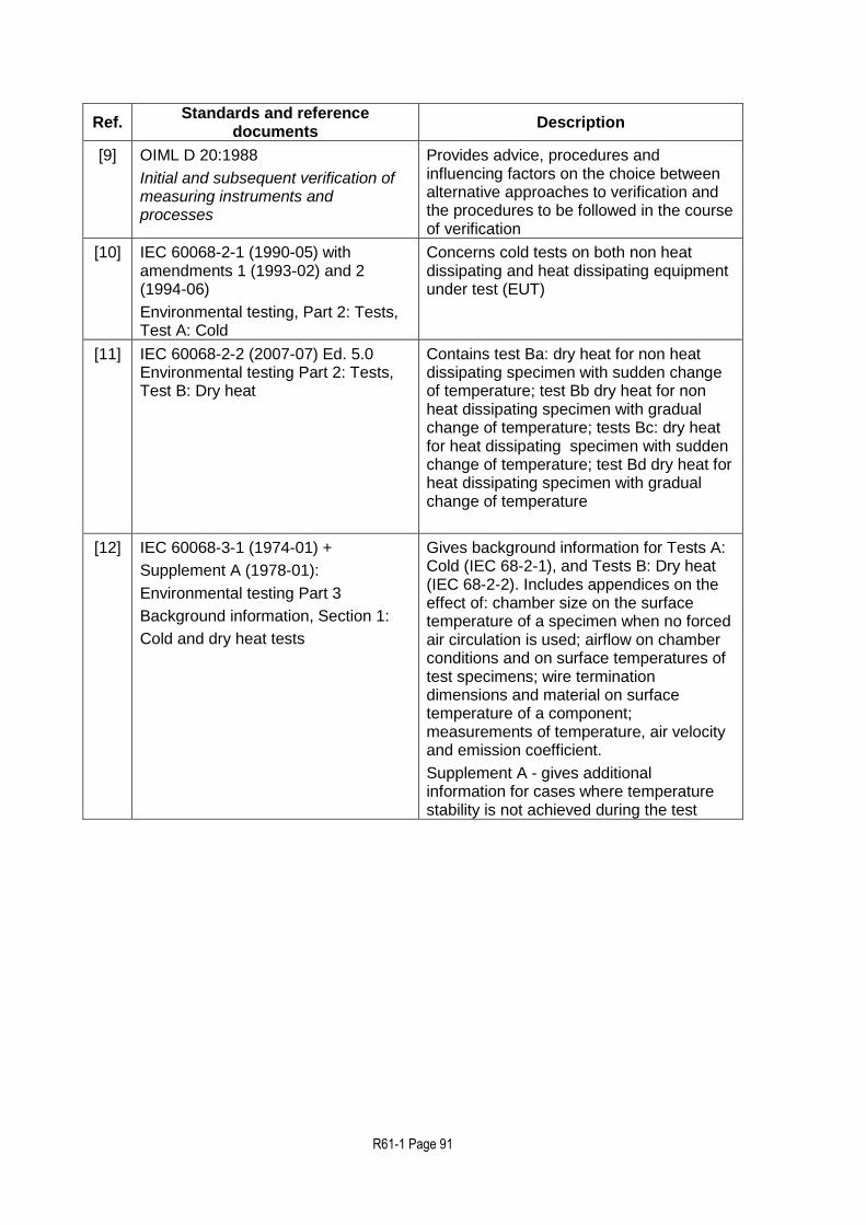
R61-1 Page 91
Ref. Standards and reference
documents Description
[9] OIML D 20:1988
Initial and subsequent verification of measuring instruments and processes
Provides advice, procedures and influencing factors on the choice between alternative approaches to verification and the procedures to be followed in the course of verification
[10] IEC 60068-2-1 (1990-05) with amendments 1 (1993-02) and 2 (1994-06)
Environmental testing, Part 2: Tests, Test A: Cold
Concerns cold tests on both non heat dissipating and heat dissipating equipment under test (EUT)
[11] IEC 60068-2-2 (2007-07) Ed. 5.0 Environmental testing Part 2: Tests, Test B: Dry heat
Contains test Ba: dry heat for non heat dissipating specimen with sudden change of temperature; test Bb dry heat for non heat dissipating specimen with gradual change of temperature; tests Bc: dry heat for heat dissipating specimen with sudden change of temperature; test Bd dry heat for heat dissipating specimen with gradual change of temperature
[12] IEC 60068-3-1 (1974-01) +
Supplement A (1978-01):
Environmental testing Part 3
Background information, Section 1:
Cold and dry heat tests
Gives background information for Tests A: Cold (IEC 68-2-1), and Tests B: Dry heat (IEC 68-2-2). Includes appendices on the effect of: chamber size on the surface temperature of a specimen when no forced air circulation is used; airflow on chamber conditions and on surface temperatures of test specimens; wire termination dimensions and material on surface temperature of a component; measurements of temperature, air velocity and emission coefficient.
Supplement A - gives additional information for cases where temperature stability is not achieved during the test

R61-1 Page 92
Ref. Standards and reference
documents Description
[13] IEC 60068-2-78 (2001-08)
Environmental testing - Part 2-78:
Tests - Test Cab: Damp heat, steady state
(IEC 60068-2-78 replaces the following withdrawn standards:
IEC 60068-2-3, test Ca and
IEC 60068-2-56, test Cb)
Provides a test method for determining the suitability of electro-technical products, components or equipment for transportation, storage and use under conditions of high humidity. The test is primarily intended to permit the observation of the effect of high humidity at constant temperature without condensation on the specimen over a prescribed period
This test provides a number of preferred severities of high temperature, high humidity and test duration. The test can be applied to both heat-dissipating and non-heat dissipating specimens. The test is applicable to small equipment or components as well as large equipment having complex interconnections with test equipment external to the chamber, requiring a set-up time which prevents the use of preheating and the maintenance of specified conditions during the installation period
[14] IEC 60068-3-4 (2001-08)
Environmental testing - Part 3-4:
Supporting documentation and guidance - Damp heat tests
Provides the necessary information to assist in preparing relevant specifications, such as standards for components or equipment, in order to select appropriate tests and test severities for specific products and, in some cases, specific types of application. The object of damp heat tests is to determine the ability of products to withstand the stresses occurring in a high relative humidity environment, with or without condensation, and with special regard to variations of electrical and mechanical characteristics. Damp heat tests may also be utilized to check the resistance of a specimen to some forms of corrosion attack
[15] IEC/TR 61000-2-1 (1990-05)
Electromagnetic compatibility (EMC) Part 2: Environment Section 1
Electromagnetic compatibility (EMC) Part 2: Environment Section 1: Description of the environment- Electromagnetic environment for low-frequency conducted disturbances and signalling in public power supply systems
[16] IEC 61000-4-1 (2006-10) Ed. 3.0 Basic EMC Publication
Electromagnetic compatibility (EMC)
Part 4: Testing and measurement techniques. Section 1: Overview of IEC 61000-4 series
Gives applicability assistance to the users and manufacturers of electrical and electronic equipment on EMC standards within the IEC 61000-4 series on testing and measurement techniques
Provides general recommendations concerning the choice of relevant tests

R61-1 Page 93
Ref. Standards and reference
documents Description
[17] IEC 60654-2 (1979-01), with amendment 1 (1992-09)
Operating conditions for industrial process measurement and control equipment - Part 2: Power
Gives the limiting values for power received by land-based and offshore industrial process measurement and control systems or parts of systems during operation
[18] IEC 61000-4-11 (2004-03) Ed 2.0
Electromagnetic compatibility (EMC)
Part 4-11: Testing and measuring techniques - Voltage dips, short interruptions and voltage variations immunity tests
Defines the immunity test methods and range of preferred test levels for electrical and electronic equipment connected to low-voltage power supply networks for voltage dips, short interruptions, and voltage variations. This standard applies to electrical and electronic equipment having a rated input current not exceeding 16 A per phase, for connection to 50 Hz or 60 Hz AC networks. It does not apply to electrical and electronic equipment for connection to 400 Hz AC networks. Tests for these networks will be covered by future IEC standards. The object of this standard is to establish a common reference for evaluating the immunity of electrical and electronic equipment when subjected to voltage dips, short interruptions and voltage variations. It has the status of a Basic EMC Publication in accordance with IEC Guide 107
[19] IEC 61000-4-4 (2004-07) Ed 2.0
Electromagnetic compatibility (EMC)
Part 4-4: Testing and measurement techniques - Electrical fast transient/burst immunity test
Establishes a common and reproducible reference for evaluating the immunity of electrical and electronic equipment when subjected to electrical fast transient/burst on supply, signal, control and earth ports. The test method documented in this part of IEC 61000-4 describes a consistent method to assess the immunity of an equipment or system against a defined phenomenon.
The standard defines:
test voltage waveform;
range of test levels;
test equipment;
verification procedures of test equipment;
test set-up; and
test procedure.
The standard gives specifications for laboratory and post-installation tests

R61-1 Page 94
Ref. Standards and reference
documents Description
[20] IEC 61000-4-5 (2005-11) Ed. 2.0Electromagnetic compatibility (EMC) - Part 4-5: Testing and measurement techniques - Surge immunity test
Relates to the immunity requirements, test methods, and range of recommended test levels for equipment to unidirectional surges caused by over-voltages from switching and lightning transients. Several test levels are defined which relate to different environment and installation conditions. These requirements are developed for and are applicable to electrical and electronic equipment. Establishes a common reference for evaluating the performance of equipment when subjected to high-energy disturbances on the power and inter-connection lines.
[21] IEC 61000-4-2 (2009) with amendment 1 (1998-01) and amendment 2 (2000-11)
Consolidated Edition: IEC 61000-4-2 (2001-04) Ed. 1.2
Electromagnetic Compatibility (EMC) - Part 4: Testing and measurement techniques - Section 2: Electrostatic discharge immunity test. Basic EMC Publication
[22] IEC 61000-4-3 (2008-04) Ed. 3.1 Electromagnetic Compatibility (EMC) - Part 4: Testing and measurement techniques - Section 3: Radiated, radio-frequency, electromagnetic field immunity test
[23] IEC 61000-4-6 (2008-10) Ed. 3.0Electromagnetic compatibility (EMC)
Part 4: Testing and measurement techniques. Section 6: Immunity to conducted disturbances, induced by radio-frequency fields
Relates to the conducted immunity requirements of electrical and electronic equipment to electromagnetic disturbances coming from intended radio-frequency (RF) transmitters in the frequency range 9 kHz up to 80 MHz. Equipment not having at least one conducting cable (such as mains supply, signal line or earth connection), which can couple the equipment to the disturbing RF fields is excluded. This standard does not intend to specify the tests to be applied to particular apparatus or systems. Its main aim is to give a general basic reference to all concerned product committees of the IEC. The product committees (or users and manufacturers of equipment) remain responsible for the appropriate choice of the test and the severity level to be applied to their equipment.
[24] OIML R 87 Quantity of product in prepackages
[25] OIML D 28 Edition 2004 (E) Conventional value of the result of weighing in air

R61-1 Page 95
Ref. Standards and reference
documents Description
26 IEC 60068-2-30 (1980-01) with amendment 1 (1985-08) Environmental testing Part 2: Tests
Test Db and guidance: Damp heat, cyclic (12 + 12-hour cycle)
Determines the suitability of components, equipment and other articles for use and/or storage under conditions of high humidity when combined with cyclic temperature changes.
Amendment No. 1 replaces the third paragraph of Clause 8, Recovery.
27 ISO 16750-2 (2003) Road vehicles - Environmental conditions
and testing for electrical and electronic equipment – Part 2: Electrical loads


![COMMITTEE DRAFT OIML/4 5 CD Date: Oct 2011May …workgroups.oiml.org/tcsc/tc-09/tc-09-sc-02/revision-of-oiml-r-50-1...Evaluation of Measuring Instruments B3:2003 [3], and to the OIML](https://static.fdocuments.net/doc/165x107/5add5cf97f8b9a9d4d8d12b0/committee-draft-oiml4-5-cd-date-oct-2011may-of-measuring-instruments-b32003.jpg)

![TITLE OF THE CD (English): Revision OIML R 85 · OIML TC8/SC1/WG2 CD02 OIML R 85: 22 November 2005 Page 2 of 47 Explanatory note [Will be deleted in the final text] As part of an](https://static.fdocuments.net/doc/165x107/6037571e69fddf4aa82271d0/title-of-the-cd-english-revision-oiml-r-85-oiml-tc8sc1wg2-cd02-oiml-r-85-22.jpg)