OIML R60-1 WD - National Measurement Institute, … number: OIML R60-1 3CD . Supersedes document:...
97
3 rd Committee Draft OIML/3CD Reference number: OIML R60-1 3CD Supersedes document: R60 (2000) OIML TC 9 : Instruments for Measuring Mass and Density Circulated to P- and O-members and liaison international bodies and external organizations for: Title: Metrological Regulation for Load Cells Part 1: Metrological and Technical Requirements Part 2: Metrological controls and performance tests TITLE OF THE CD (English): OIML R 60- Parts 1 and 2 Metrological Regulation for Load Cells Part 1: Metrological and Technical Requirements Part 2: Metrological controls and performance tests TITRLE DU CD (French): OIML R 60-1 et -2 Réglementation métrologique des celleules de pesée Partie 1: Exigences métrologiques et techniques, Partie 2: Contrôles métrologiques et essais de performance Original version in: English
Transcript of OIML R60-1 WD - National Measurement Institute, … number: OIML R60-1 3CD . Supersedes document:...
3rd Committee Draft OIML/3CD
Reference number: OIML R60-1 3CD Supersedes document: R60 (2000)
OIML TC 9 : Instruments for Measuring Mass and Density
Circulated to P- and O-members and liaison international bodies and external organizations for:
Title: Metrological Regulation for Load Cells Part 1: Metrological and Technical
Requirements Part 2: Metrological controls and
performance tests
TITLE OF THE CD (English): OIML R 60- Parts 1 and 2 Metrological Regulation for Load Cells Part 1: Metrological and Technical Requirements Part 2: Metrological controls and performance tests TITRLE DU CD (French): OIML R 60-1 et -2 Réglementation métrologique des celleules de pesée Partie 1: Exigences métrologiques et techniques, Partie 2: Contrôles métrologiques et essais de performance Original version in: English

Part 1 OIML R60: 2013
1
Contents PART 1 METROLOGICAL AND TECHNICAL REQUIREMENTS 2 1. INTRODUCTION 2 2. SCOPE 2 3. TERMINOLOGY (TERMS AND DEFINITIONS) 4 3.1. GENERAL DEFINITIONS 4 3.2. CATEGORIES OF LOAD CELLS 5 3.3. CONSTRUCTION OF LOAD CELLS 5 3.4. METROLOGICAL CHARACTERISTICS OF A LOAD CELL 6 3.5. RANGE, CAPACITY AND OUTPUT TERMS 7 3.6. ILLUSTRATION OF CERTAIN DEFINITIONS 9 3.7. MEASUREMENT AND ERROR TERMS 10 3.8. INFLUENCES AND REFERENCE CONDITIONS 11 3.9. ABBREVIATIONS 12 4. DESCRIPTION OF LOAD CELLS 12 5. UNITS OF MEASUREMENT 12 6. METROLOGICAL REQUIREMENTS 12 6.1. PRINCIPLE OF LOAD CELL CLASSIFICATION 13 6.2. MEASURING RANGES 15 6.3. MAXIMUM PERMISSIBLE MEASUREMENT ERRORS 16 6.4. REPEATABILITY ERROR 17 6.5. PERMISSIBLE VARIATION OF RESULTS UNDER REFERENCE CONDITIONS 18 6.6. INFLUENCE QUANTITIES (RATED OPERATING CONDITIONS) 18 6.7. REQUIREMENTS FOR LOAD CELLS EQUIPPED WITH ELECTRONICS 20 7. TECHNICAL REQUIREMENTS 24 7.1. SOFTWARE 24 7.2. INSCRIPTIONS AND PRESENTATION OF LOAD CELL INFORMATION 25 PART 2 METROLOGICAL CONTROLS AND PERFORMANCE TESTS 30 8 METROLOGICAL CONTROLS 30 8.1 LIABILITY TO LEGAL METROLOGICAL CONTROLS 30 8.2 RESPONSIBILITY FOR COMPLIANCE WITH THE REQUIREMENTS 30 9 TYPE EVALUATION 30 9.1 SCOPE 30 9.2 TEST REQUIREMENTS 31 9.3 SELECTION OF SPECIMENS FOR EVALUATION 31 9.4 SELECTION OF LOAD CELLS WITHIN A FAMILY 32 9.5 DOCUMENTATION 33 9.6 EXAMINATIONS 34 9.7 PERFORMANCE TESTS 34 9.8 RULES CONCERNING THE DETERMINATION OF ERRORS 37 9.9 VARIATION OF RESULTS UNDER REFERENCE CONDITIONS 39 9.10 TEST PROCEDURES 39 9.11 TEST SEQUENCE 61 9.12 OIML CERTIFICATE 62 ANNEX A (MANDATORY) DEFINITIONS FROM OTHER APPLICABLE INTERNATIONAL
PUBLICATIONS A-1 ANNEX B (MANDATORY) OIML CERTIFICATE OF CONFORMITY FOR LOAD CELLS -
FORMAT OF CERTIFICATE B-1 ANNEX C (INFORMATIVE) OIML CERTIFICATE OF CONFORMITY FOR LOAD CELLS C-1 ANNEX D (INFORMATIVE) SELECTION OF LOAD CELL(S) FOR TESTING - A PRACTICAL
EXAMPLE D-1 ANNEX E (INFORMATIVE) LOAD TRANSMISSION TO THE LOAD CELL E-1 BIBLIOGRAPHY i
OIML R60: 2013 Part 1
2
Part 1 Metrological and technical requirements
1. Introduction The 3rd Committee Draft copy of OIML R60 Parts 1&2 represents changes to the previous 2nd CD based on the Project Group’s (TC9 p1) comments. The subject of this Recommendation, load cells comprise a distinct element or module within other complex instruments. Load cells do not produce distinct quantitative values that are inherently identified or associated with denominations or units. The data that can be extracted from a load cell is simply a measurement of change in the output of the load cell in relation to the input. This relative change must be converted by other elements or modules within an instrument into values that are meaningful measurements which can then be used to identify a quantity. To assist the reader in the review of the formatting of this Third Committee Draft, the document has been placed in a tabular form using the following numbering scheme. As illustrated below in “2 Scope”, the left-hand column contains reference numbers that are associated with the 2000 edition of R60. Paragraphs that appear without a reference number in the left-hand column represent new entries in the document. A significant change from the 2CD to the 3CD is the formatting of test procedures found in sections 9.10.5 through 9.10.7. These changes largely were done by copying tables from OIML D11 [1] and pasting them into this draft of OIML R60 with some editing done where it was considered appropriate. Part 1 (Metrological and Technical Requirements) and Part 2 (Metrological Controls and Performance Tests) of this Recommendation are a combined publication, Part 3 (Test Report Format) is a separate document.
1 (2000 Ed.)
2. Scope
Part 1 OIML R60: 2013
3
1.1 2.1.
This Recommendation prescribes the principal metrological static requirements and static evaluation procedures for load cells used in the determination of conformity to this recommendation. It is intended to provide authorities with uniform means for determining the metrological characteristics of load cells used in measuring instruments that are subjected to metrological controls.
It is acknowledged that test procedures found in Part 2 of this Recommendation (see section 9) are useful in the evaluation of load cells that are currently found in service (i.e., primarily strain gauge design) however, there may be variations in designs for load cells that will require additional or modified test procedures to appropriately evaluate them. These additional test procedures may be annexed when necessary.
Except where otherwise specified, these requirements apply regardless of the technology or operating principle employed. The requirements and evaluation procedures in this Recommendation have been drafted to be non-specific with regard to load cell design and their operating principles.
1.2 2.2.
This Recommendation utilizes the principle that several measurement errors shall be considered together when applying load cell performance characteristics to the permitted error envelope. Thus, it is not considered appropriate to specify individual errors for given characteristics (e.g., non-linearity, hysteresis, effects of influence factors), but rather to consider the total error envelope allowed for a load cell as the limiting factor. The use of an error envelope allows the balancing of the individual contributions to the total error of measurement while still achieving the intended final result.
Note: the error envelope may be defined as the curves that provide the boundary of the maximum permissible errors (see Table 4) as a function of the force introduced by the applied load (expressed in mass units) over the measuring range. The combined errors determined may be positive or negative and include the effects of nonlinearity, hysteresis and temperature.
1.3 2.3.
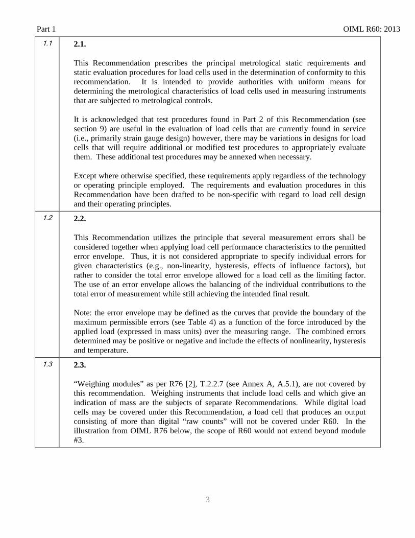
“Weighing modules” as per R76 [2], T.2.2.7 (see Annex A, A.5.1), are not covered by this recommendation. Weighing instruments that include load cells and which give an indication of mass are the subjects of separate Recommendations. While digital load cells may be covered under this Recommendation, a load cell that produces an output consisting of more than digital “raw counts” will not be covered under R60. In the illustration from OIML R76 below, the scope of R60 would not extend beyond module #3.
OIML R60: 2013 Part 1
4
From OIML R76: Definition of typical modules within a weighing system (other combinations are possible)
Figure 1. Weighing Modules
2 3. Terminology (Terms and definitions)
The terms most frequently used in the load cell field and their definitions are given below (see 3.7 for an illustration of certain definitions). The terminology used in this Recommendation conforms to OIML V 1 International Vocabulary of Basic and General Terms in Metrology (VIM) [3], to OIML V 2 International Vocabulary of Terms in Legal Metrology (VIML) [4], to OIML D 9 Principles of metrological supervision [5], to OIML D 11 General Requirements for electronic measuring instruments [1], and to OIML B 3 OIML Certificate System for Measuring Instruments [6]. In addition, for the purposes of this Recommendation, the following definitions apply:
2.1
3.1. General definitions
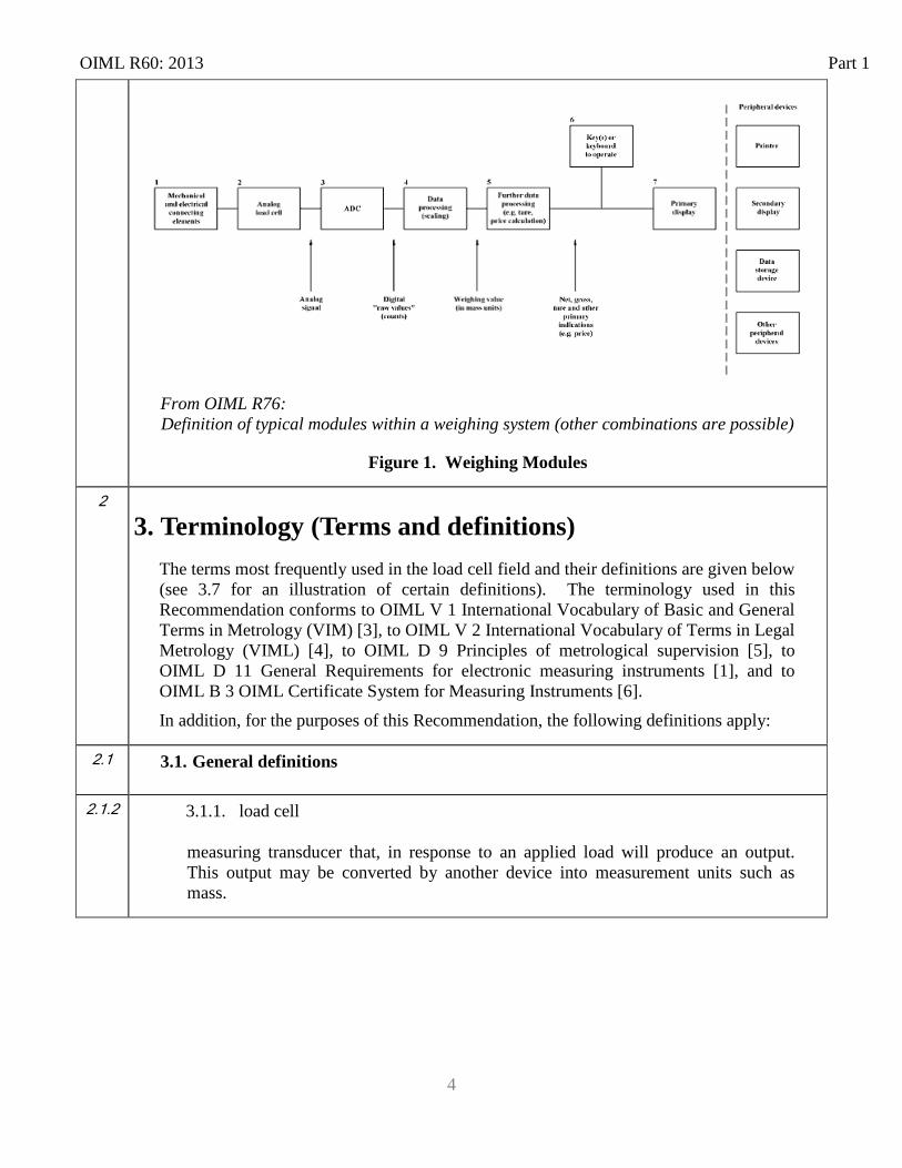
2.1.2 3.1.1. load cell
measuring transducer that, in response to an applied load will produce an output. This output may be converted by another device into measurement units such as mass.
Part 1 OIML R60: 2013
5
2.1.3 3.1.2. load cell equipped with electronics
load cell employing an assembly of electronic components having a recognizable function of its own. Load cells that include intrinsically (as a minimum) the function of analog to digital output conversion, are referred to as “digital load cells” and are examples of load cells equipped with electronics. Additional features such as temperature compensation and signal filtering may also be an intrinsic functions of the load cell equipped with electronics. Note: Passive elements such as strain gauges are not considered electronic components for the purpose of this recommendation
2.1.4 3.1.3. performance test
test to verify whether the load cell under test is capable of performing its intended functions.
3.2. Categories of Load Cells 2.1.1 3.2.1. Application of load
2.1.1.1 3.2.1.1. compression loading
compressive force applied to the load receptor of a load cell.
2.1.1.2 3.2.1.2. tension loading
tension force applied to the load receptor of a load cell.
3.3. Construction of load cells 3.3.1. strain gauge
analog resistive element that is bonded to a load cell structure and changes resistance depending on the compression or tension deformation of the load cell structure
OIML R60: 2013 Part 1
6
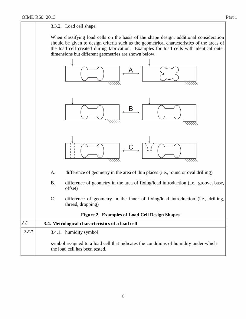
3.3.2. Load cell shape
When classifying load cells on the basis of the shape design, additional consideration should be given to design criteria such as the geometrical characteristics of the areas of the load cell created during fabrication. Examples for load cells with identical outer dimensions but different geometries are shown below.
A. difference of geometry in the area of thin places (i.e., round or oval drilling)
B. difference of geometry in the area of fixing/load introduction (i.e., groove, base, offset)
C. difference of geometry in the inner of fixing/load introduction (i.e., drilling, thread, dropping)
Figure 2. Examples of Load Cell Design Shapes 2.2 3.4. Metrological characteristics of a load cell 2.2.2 3.4.1. humidity symbol
symbol assigned to a load cell that indicates the conditions of humidity under which the load cell has been tested.
Part 1 OIML R60: 2013
7
2.2.3. 3.4.2. load cell family
for the purposes of type evaluation, a load cell family consists of load cells that are of:
• the same material or combination of materials (for example, mild steel, stainless steel or aluminum);
• the same design of the measurement technique (for example, strain gauges bonded to metal);
• the same method of construction (for example, shape, sealing of strain gauges, mounting method, manufacturing method); the same set of specifications (for example, output rating, input impedance, supply voltage, cable details); and
• one or more load cell groups. Note: The examples provided are not intended to be limiting.
2.2.3.1 3.4.2.1. load cell group
all load cells within a family possessing identical metrological characteristics (as listed in 6.1.5 – including: class; nmax; temperature rating; etc.).
2.3 3.5. Range, capacity and output terms
2.3.1 3.5.1. load cell interval
part of the load cell measuring range into which that range is divided.
2.3.2 3.5.2. load cell measuring range (DR)
range of values of the measured quantity for which the result of measurement should not be affected by an error exceeding the maximum permissible error (MPE) (see Annex A: A.1.11). DR is the range between the maximum load of the measuring range Dmax and minimum load of the measuring range Dmin DR = (Dmax – Dmin)
2.3.3 3.5.3. load cell output
measurable quantity into which a load cell converts the measured input quantity.
2.3.4 3.5.4. load cell verification interval (v)
load cell interval, expressed in units of mass, used in the test of the load cell for accuracy classification.
OIML R60: 2013 Part 1
8
2.3.5 3.5.5. maximum capacity (Emax)
largest value of a force expressed in units of mass, which may be applied to a load cell without the result exceeding the MPE (see Annex A: A.1.11).
2.3.6 3.5.6. maximum load of the measuring range (Dmax)
largest value of force introduced to a load cell during test or use (expressed in units of mass).
3.5.7. maximum measuring range (ER)
range between maximum capacity Emax and minimum dead load Emin [ER = (Emax – Emin)]
2.3.7 3.5.8. maximum number of load cell verification intervals (nmax)
maximum number of load cell verification intervals into which the load cell measuring range may be divided for which the result of measurement will not be affected by an error exceeding the MPE (see Annex A: A.1.11).
2.3.8 3.5.9. minimum dead load (Emin)
smallest value of force introduced by a load (expressed in mass units) that may be applied to a load cell without the result exceeding the MPE (see Annex A: A.1.11).
2.3.9 3.5.10. minimum dead load output return (DR)
the observed difference of output, expressed in load cell verification intervals at the minimum load of the measuring range (Dmin), measured before and after application of a load of Dmax
2.3.10 3.5.11. minimum load cell verification interval (vmin)
smallest load cell verification interval into which the load cell measuring range DR (Dmax –Dmin) can be divided.
2.3.11 3.5.12. minimum load of the measuring range (Dmin)
smallest value for a load which is applied to a load cell during test or use. Note: For the limits on Dmin during testing, see 9.7.3.4.
2.3.12 3.5.13. number of load cell verification intervals (n)
number of load cell verification intervals into which the load cell measuring range is divided.
Part 1 OIML R60: 2013
9
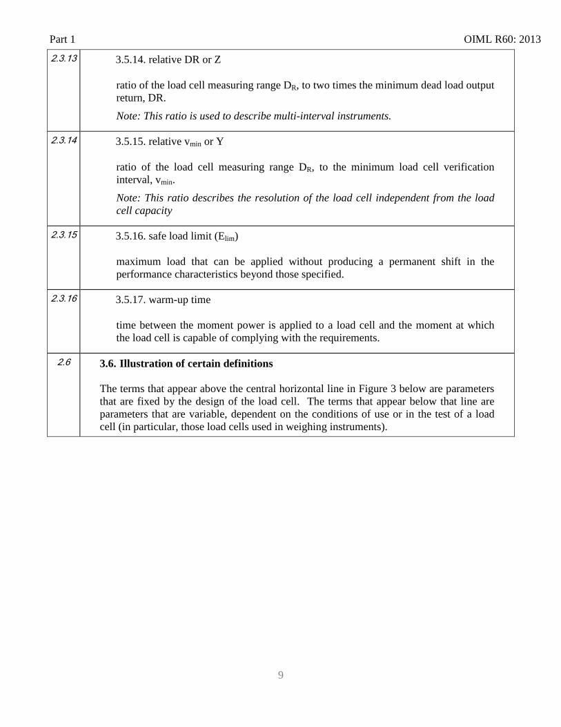
2.3.13 3.5.14. relative DR or Z
ratio of the load cell measuring range DR, to two times the minimum dead load output return, DR. Note: This ratio is used to describe multi-interval instruments.
2.3.14 3.5.15. relative vmin or Y
ratio of the load cell measuring range DR, to the minimum load cell verification interval, vmin. Note: This ratio describes the resolution of the load cell independent from the load cell capacity
2.3.15 3.5.16. safe load limit (Elim)
maximum load that can be applied without producing a permanent shift in the performance characteristics beyond those specified.
2.3.16 3.5.17. warm-up time
time between the moment power is applied to a load cell and the moment at which the load cell is capable of complying with the requirements.
2.6 3.6. Illustration of certain definitions
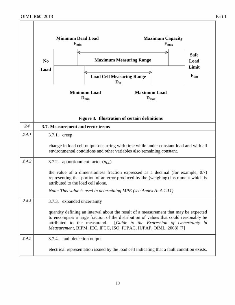
The terms that appear above the central horizontal line in Figure 3 below are parameters that are fixed by the design of the load cell. The terms that appear below that line are parameters that are variable, dependent on the conditions of use or in the test of a load cell (in particular, those load cells used in weighing instruments).
OIML R60: 2013 Part 1
10
Minimum Dead Load Emin Maximum Capacity
Emax
No
Load
Maximum Measuring Range Safe
Load Limit
Elim
Load Cell Measuring Range DR
Minimum Load Dmin
Maximum Load Dmax
Figure 3. Illustration of certain definitions 2.4 3.7. Measurement and error terms
2.4.1 3.7.1. creep
change in load cell output occurring with time while under constant load and with all environmental conditions and other variables also remaining constant.
2.4.2 3.7.2. apportionment factor (pLC)
the value of a dimensionless fraction expressed as a decimal (for example, 0.7) representing that portion of an error produced by the (weighing) instrument which is attributed to the load cell alone. Note: This value is used in determining MPE (see Annex A: A.1.11)
2.4.3 3.7.3. expanded uncertainty
quantity defining an interval about the result of a measurement that may be expected to encompass a large fraction of the distribution of values that could reasonably be attributed to the measurand. [Guide to the Expression of Uncertainty in Measurement, BIPM, IEC, IFCC, ISO, IUPAC, IUPAP, OIML, 2008] [7]
2.4.5 3.7.4. fault detection output
electrical representation issued by the load cell indicating that a fault condition exists.
Part 1 OIML R60: 2013
11
2.4.6 3.7.5. hysteresis error
difference in load cell output readings for the same applied force between the reading obtained by increasing the load from minimum load (Dmin), and the reading obtained by decreasing the load from maximum load (Dmax).
2.4.8 3.7.6. load cell intrinsic error
error resulting from a load cell, determined under reference conditions (see Annex A, A.1.7).
2.4.10 3.7.7. non-linearity
deviation from the average of the values of load cell signals from a straight line through zero force applied and maximum force applied.
2.4.12 3.7.8. repeatability error
difference between load cell output readings taken from consecutive tests under the same loading and environmental conditions of measurement.
2.4.15 3.7.9. span stability
capability of a load cell to maintain the load cell output of the load cell’s measuring range (DR) over a period of use within specified limits.
2.4.16 3.7.10. temperature effect on minimum dead load output
change in minimum dead load output due to a change in ambient temperature.
2.4.17 3.7.11. temperature effect on sensitivity
change in sensitivity due to a change in ambient temperature.
2.5 3.8. Influences and reference conditions
For definition of terms: “influence quantity”; “rated operating conditions”; and “reference conditions” refer to Annex A
OIML R60: 2013 Part 1
12
3.9. Abbreviations
AC Alternating Current DC Direct Current EMC Electro Magnetic Compatibility IEC International Electrotechnical Committee ISO International Organization for Standardization I/O Input/Output MPE Maximum Permissible Error OIML International Organization of Legal Metrology VIM International Vocabulary of Metrology – Basic and General Concepts and
Associated Terms
4. Description of Load Cells
A load cell provides an output proportional to a force resulting from applying a load. Load cells may be used as a single transducer or applied together with other load cells in a system where the design allows such application. The term “load cell” in this Recommendation is not limited to any particular type of technology or design principle. While many technologies are used in the design of load cells, those used in legal metrology applications are commonly designed to provide an output relative to an input stimulus based on electrical current. Both analog and digital outputs are recognized in load cells within that category. Although strain gauge technology was a primary focus in the development of R60, it is to be understood that load cells that operate using other principles may also be evaluated under this Recommendation. Variations of transducers that operate using alternative basis of input/output may include, but are not limited to: pressure (e.g., hydraulic, pneumatic); vibratory frequency; and magnetic forces. The term load cell may describe an elemental component/module or a somewhat more complex instrument including constituents that perform functions such as signal filtering and analog-to-digital conversion.
3 5. Units of measurement
The units of measurement resulting from the output of a load cell that is incorporated as a component of an instrument are required to conform to the Recommendation(s) applicable to the instrument.
4 6. Metrological requirements
Part 1 OIML R60: 2013
13
4.1 6.1. Principle of load cell classification The classification of load cells into specific accuracy classes is provided to facilitate their application to various measuring systems. In the application of this Recommendation, it should be recognized that the effective performance of a particular load cell may be improved by compensation within the measuring system with which it is applied. Therefore, it is not the intent of this Recommendation to require that a load cell be of the same accuracy class as the measuring system in which it may be used. Nor does it require that a measuring instrument, giving indications of mass for example, use a load cell which has been separately approved. All data/items found in 6.1.1 to 6.1.7 shall be specified by the manufacturer
4.2
6.1.1. Accuracy classes and their symbols
Load cells shall be ranked, according to their overall performance capabilities, into four accuracy classes whose designations are as follows:
Class A; Class B; Class C; Class D.
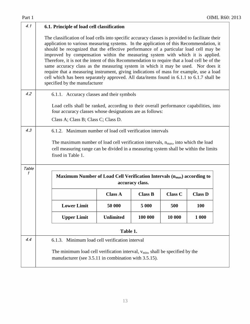
4.3 6.1.2. Maximum number of load cell verification intervals
The maximum number of load cell verification intervals, nmax, into which the load cell measuring range can be divided in a measuring system shall be within the limits fixed in Table 1.
Table 1
Table 1.
Maximum Number of Load Cell Verification Intervals (nmax) according to accuracy class.
Class A Class B Class C Class D
Lower Limit 50 000 5 000 500 100
Upper Limit Unlimited 100 000 10 000 1 000
4.4 6.1.3. Minimum load cell verification interval
The minimum load cell verification interval, vmin, shall be specified by the manufacturer (see 3.5.11 in combination with 3.5.15).
OIML R60: 2013 Part 1
14
4.5 6.1.4. Supplementary classifications
Load cells shall also be classified by the type of load applied to the load cell wherever there would be a risk of confusing the type of loading (i.e., compression loading, tension loading or, universal). A load cell may bear different classifications for different types of load applied to the load cell. The type of load for which the classification(s) applies(y) shall be specified. For multiple capacity load cells, each capacity shall be classified separately.
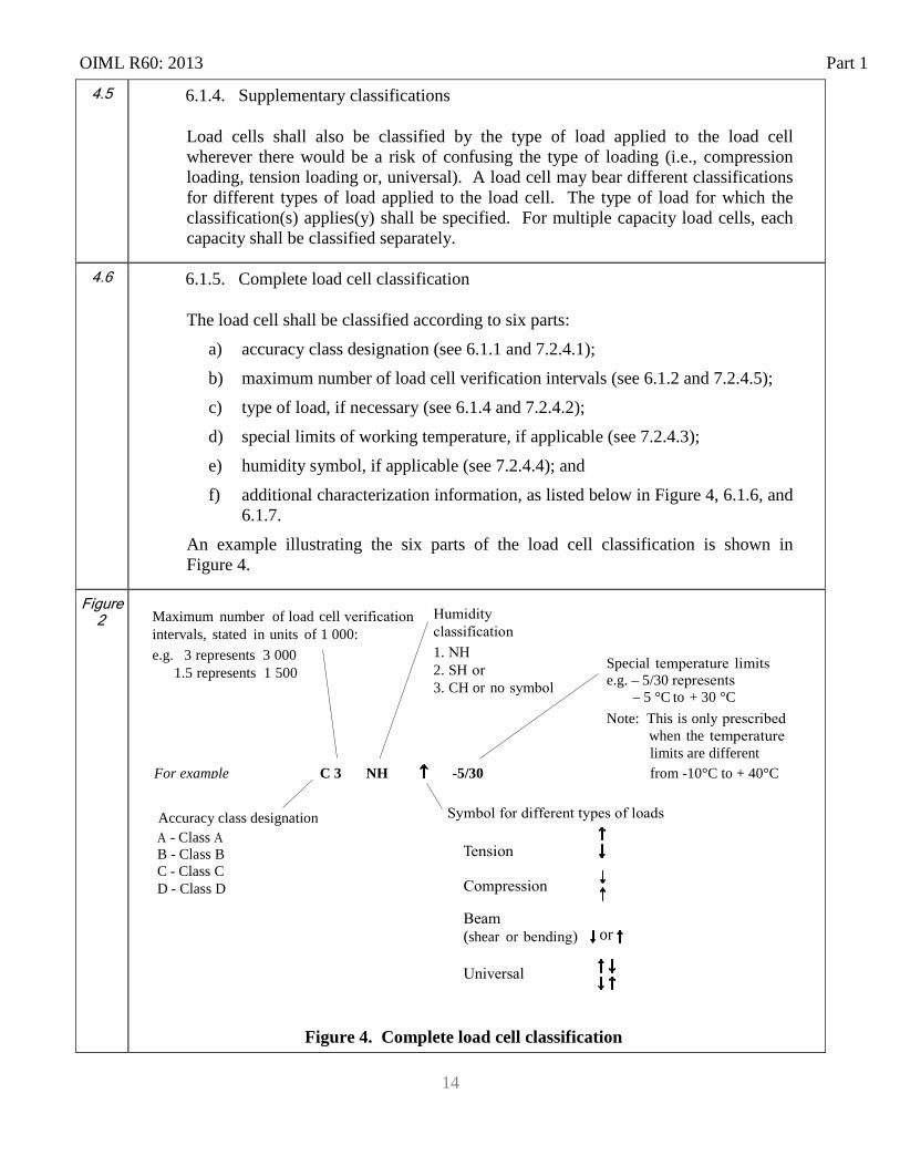
4.6 6.1.5. Complete load cell classification
The load cell shall be classified according to six parts: a) accuracy class designation (see 6.1.1 and 7.2.4.1); b) maximum number of load cell verification intervals (see 6.1.2 and 7.2.4.5); c) type of load, if necessary (see 6.1.4 and 7.2.4.2); d) special limits of working temperature, if applicable (see 7.2.4.3); e) humidity symbol, if applicable (see 7.2.4.4); and f) additional characterization information, as listed below in Figure 4, 6.1.6, and
6.1.7. An example illustrating the six parts of the load cell classification is shown in Figure 4.
Figure 2
Figure 4. Complete load cell classification
(shear or
1. 2. SH 3. CH or no
Special e.g. – 5/30
– 5 °C to + 30 °C Note: This is only
when the
Maximum number of load cell intervals, stated in units of 1 000: e.g. 3 represents 3 000
1.5 represents 1 500
limits are different from -10°C to + 40°C
- Class B - Class B C - Class C D - Class D
or
Accuracy class designation
For example C 3 NH -5/30
Part 1 OIML R60: 2013
15
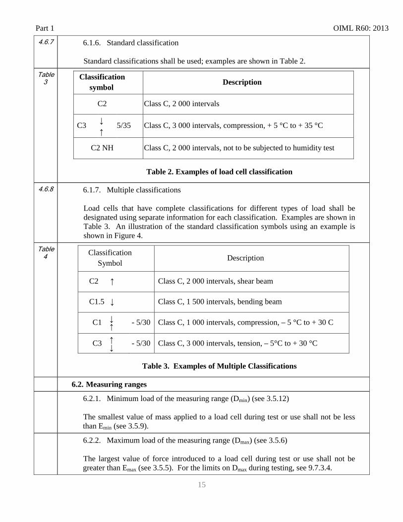
4.6.7 6.1.6. Standard classification
Standard classifications shall be used; examples are shown in Table 2.
Table 3
Classification symbol
Description
C2 Class C, 2 000 intervals
C3 ↓ 5/35 Class C, 3 000 intervals, compression, + 5 °C to + 35 °C ↑
C2 NH Class C, 2 000 intervals, not to be subjected to humidity test
Table 2. Examples of load cell classification
4.6.8 6.1.7. Multiple classifications
Load cells that have complete classifications for different types of load shall be designated using separate information for each classification. Examples are shown in Table 3. An illustration of the standard classification symbols using an example is shown in Figure 4.
Table 4 Classification
Symbol Description
C2 ↑ Class C, 2 000 intervals, shear beam
C1.5 ↓ Class C, 1 500 intervals, bending beam
C1 ↓ ↑ - 5/30 Class C, 1 000 intervals, compression, – 5 °C to + 30 C
C3 ↑ ↓ - 5/30 Class C, 3 000 intervals, tension, – 5°C to + 30 °C
Table 3. Examples of Multiple Classifications
6.2. Measuring ranges 6.2.1. Minimum load of the measuring range (Dmin) (see 3.5.12)
The smallest value of mass applied to a load cell during test or use shall not be less than Emin (see 3.5.9).
6.2.2. Maximum load of the measuring range (Dmax) (see 3.5.6)
The largest value of force introduced to a load cell during test or use shall not be greater than Emax (see 3.5.5). For the limits on Dmax during testing, see 9.7.3.4.
OIML R60: 2013 Part 1
16
5
6.3. Maximum permissible measurement errors
Under the rated operating conditions in 6.6, the maximum permissible error (MPE) shall not exceed the values stated in 6.5
These MPEs are applicable after increasing as well as decreasing the force applied (i.e., they include hysteresis).
Note: The term “measurement error” in this Recommendation refers to load cell measurement errors.
5.1 6.3.1. Maximum permissible errors for each accuracy class
The maximum permissible measurement errors for each accuracy class are related to the maximum number of load cell verification intervals (nmax) specified for the load cell (see 6.1.2) and to the actual value of the load cell verification interval, v.
Part 1 OIML R60: 2013
17
5.1.1 Table
5
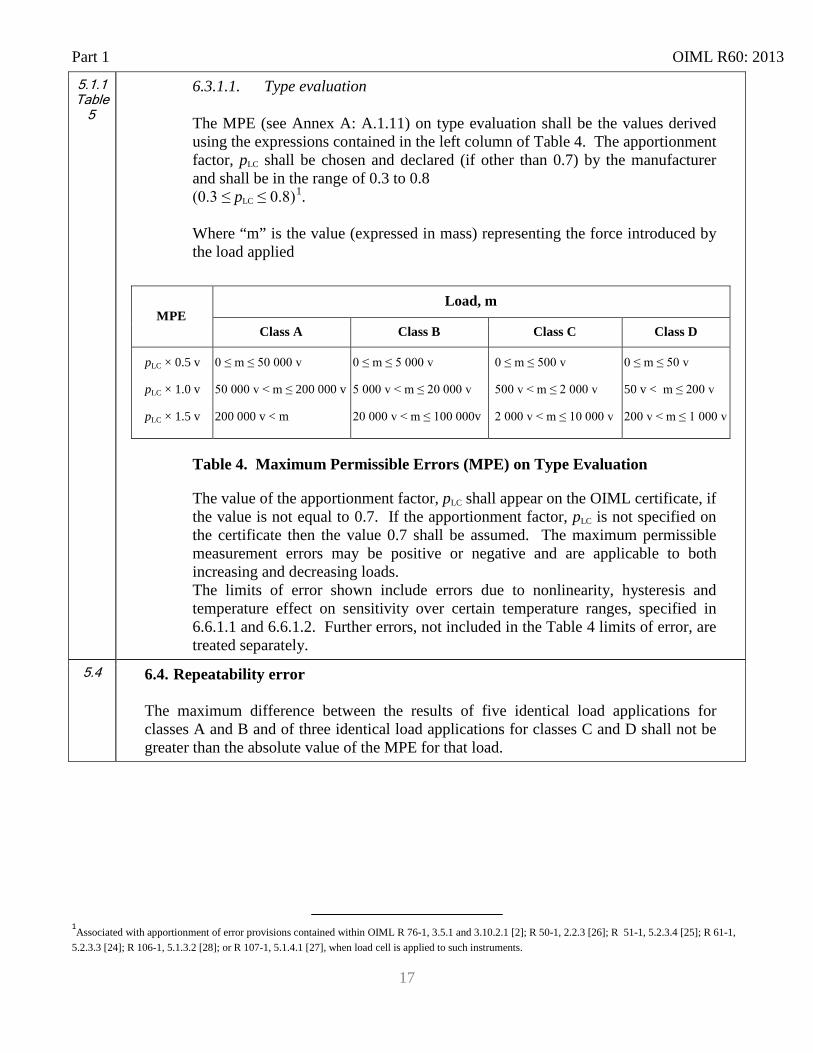
6.3.1.1. Type evaluation
The MPE (see Annex A: A.1.11) on type evaluation shall be the values derived using the expressions contained in the left column of Table 4. The apportionment factor, pLC shall be chosen and declared (if other than 0.7) by the manufacturer and shall be in the range of 0.3 to 0.8 (0.3 ≤ pLC ≤ 0.8)1. Where “m” is the value (expressed in mass) representing the force introduced by the load applied
MPE Load, m
Class A Class B Class C Class D
pLC × 0.5 v
pLC × 1.0 v
pLC × 1.5 v
0 ≤ m ≤ 50 000 v
50 000 v < m ≤ 200 000 v
200 000 v < m
0 ≤ m ≤ 5 000 v
5 000 v < m ≤ 20 000 v
20 000 v < m ≤ 100 000v
0 ≤ m ≤ 500 v
500 v < m ≤ 2 000 v
2 000 v < m ≤ 10 000 v
0 ≤ m ≤ 50 v
50 v < m ≤ 200 v
200 v < m ≤ 1 000 v
Table 4. Maximum Permissible Errors (MPE) on Type Evaluation
The value of the apportionment factor, pLC shall appear on the OIML certificate, if the value is not equal to 0.7. If the apportionment factor, pLC is not specified on the certificate then the value 0.7 shall be assumed. The maximum permissible measurement errors may be positive or negative and are applicable to both increasing and decreasing loads. The limits of error shown include errors due to nonlinearity, hysteresis and temperature effect on sensitivity over certain temperature ranges, specified in 6.6.1.1 and 6.6.1.2. Further errors, not included in the Table 4 limits of error, are treated separately.
5.4 6.4. Repeatability error
The maximum difference between the results of five identical load applications for classes A and B and of three identical load applications for classes C and D shall not be greater than the absolute value of the MPE for that load.
1Associated with apportionment of error provisions contained within OIML R 76-1, 3.5.1 and 3.10.2.1 [2]; R 50-1, 2.2.3 [26]; R 51-1, 5.2.3.4 [25]; R 61-1, 5.2.3.3 [24]; R 106-1, 5.1.3.2 [28]; or R 107-1, 5.1.4.1 [27], when load cell is applied to such instruments.
OIML R60: 2013 Part 1
18
5.3 6.5. Permissible variation of results under reference conditions 5.3.1 6.5.1. Creep
The difference between the reading taken upon the application of a maximum load (Dmax) and the reading observed within and after 30 minutes of exposure of 90% to 100% of Emax shall not exceed 0.7 times the value of MPE for the applied load.* The difference in readings taken after 20 minutes of exposure to 90% to 100% of Emax and at 30 minutes of exposure to 90% to 100% of Emax shall not exceed 0.15 times the absolute value of MPE. *Regardless of any value declared by the manufacturer for the apportionment factor, pLC, the MPE for creep shall be determined from Table 4 using the apportionment factor, pLC = 0.7. “
5.3.2
6.5.2. Minimum dead load output return
The difference between the initial reading of the minimum load output (Dmin) and the reading of Dmin after being exposed to a load of 90% to 100% of Emax for 30 minutes shall not exceed half the value of the load cell verification interval (0.5 v).
5.5
6.6. Influence quantities (Rated operating conditions)
Load cells are to be evaluated under the conditions specified in 6.6.1 - 6.6.3. An evaluation may include additional special testing performed under conditions that vary from those specified in 6.6.1 - 6.6.3 if requested and specified by the submitter of the load cell for evaluation. This special testing may be performed in addition to, but not instead of testing under the specified conditions in 6.6.1 – 6.6.3. Load cells that are equipped with functions typically performed by complete instruments (e.g., analog to digital conversion) may be required to be evaluated against additional requirements contained in other OIML Recommendations for those complete instruments. These additional evaluations are outside the scope of this Recommendation.
5.5.1 6.6.1. Temperature
5.5.1.1 6.6.1.1. Temperature limits
Excluding temperature effects on minimum dead load output, the load cell shall perform within the limits of error in 6.3.1.1 over the temperature range of – 10 °C to + 40 °C, unless otherwise specified as in 6.6.1.2 below. Note: National legislation may prescribe alternate temperature limits with a range of 50 °C or more as appropriate for local climatic conditions and the environmental conditions that can be anticipated.
Part 1 OIML R60: 2013
19
5.5.1.2 6.6.1.2. Special limits
Load cells for which particular limits of working temperature are specified shall satisfy, within those ranges, the conditions defined in 6.3.1.1. The span of these ranges shall be at least: 5 °C for load cells of class A; 15 °C for load cells of class B; 30 °C for load cells of classes C and D.
5.5.1.3 6.6.1.3. Temperature effect on minimum dead load output
The minimum dead load output of the load cell over the temperature range, as specified in 6.6.1.1 or 6.6.1.2, shall not vary by an amount greater than the apportionment factor, pLC, times the minimum load cell verification interval, vmin, for any change in ambient temperature of: 2 °C for load cells of class A; 5 °C for load cells of class B, C and D.
5.5.2 6.6.2. Barometric pressure
The output of the load cell shall not vary by an amount greater than the minimum load cell verification interval, vmin, for any incremental change in barometric pressure equivalent to 1 kPa.
5.5.3 6.6.3. Humidity
With respect to humidity conditions, this Recommendation defines 3 humidity classes: CH (as standard), NH, and SH. In case of class NH, or SH, the class designation shall be marked on the load cell. In the case of class CH, class designation marking of the load cell is not mandatory.
5.5.3.1 6.6.3.1. Humidity error – CH or unmarked load cells
This requirement is only applicable to load cells marked CH or with no humidity symbol marking and not applicable to load cells marked NH or SH. The influence of exposure to temperature cycles specified in 9.10.5.12 on the load cell output for minimum load shall not be greater than 4 % of the difference between the output on the maximum capacity, Emax, and that at the minimum dead load Emin. The influence of exposure to temperature cycles specified in 9.10.5.12 on the load cell output for the maximum load shall not be greater than the load cell verification interval v.
OIML R60: 2013 Part 1
20
5.5.3.2 6.6.3.2. Humidity error – SH marked load cells
This requirement is only applicable to load cells marked SH and not applicable to load cells marked NH or CH or with no humidity symbol marking.
A load cell shall meet the applicable MPE when exposed to conditions of relative humidity variations as specified in 9.10.6
6 6.7. Requirements for load cells equipped with electronics 6.1 6.7.1. General requirements
In addition to the other requirements of this Recommendation, a load cell equipped with electronics shall comply with the following requirements. The MPE shall be determined using an apportionment factor, pLC, equal to 1.0 (pLC = 1.0) substituted for the apportionment factor, pLC, that is declared by the manufacturer and applied to the other requirements.
If a load cell is configured with substantial additional electronic functions (e.g., display of indications, frequency counter) that are typical of an electronic weighing instrument, it may be considered outside the scope of this Recommendation and need to undergo additional evaluation using requirements contained in other OIML Recommendations which are applicable to complete weighing instruments.
6.1.1 6.7.1.1. Faults
A load cell equipped with electronics shall be designed and manufactured such that when it is exposed to electrical disturbances either:
a) significant faults do not occur; or b) significant faults are detected and acted upon.
If significant faults do occur, and the load cell is equipped with the intelligence to detect and act upon significant faults through the instrument that the load cell is installed in, the reporting of and acting upon significant faults would then be evaluated under the appropriate Recommendation for the complete instrument. Messages of significant faults should not be confused with other messages presented. Note: A fault equal to or smaller than the load cell verification interval, v, is allowed.
Part 1 OIML R60: 2013
21
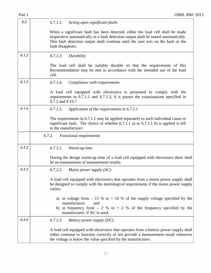
6.2 6.7.1.2. Acting upon significant faults
When a significant fault has been detected, either the load cell shall be made inoperative automatically or a fault detection output shall be issued automatically. This fault detection output shall continue until the user acts on the fault or the fault disappears.
6.1.2 6.7.1.3. Durability
The load cell shall be suitably durable so that the requirements of this Recommendation may be met in accordance with the intended use of the load cell.
6.1.3 6.7.1.4. Compliance with requirements
A load cell equipped with electronics is presumed to comply with the requirements in 6.7.1.1 and 6.7.1.3, if it passes the examinations specified in 6.7.2 and 9.10.7
6.1.4 6.7.1.5. Application of the requirements in 6.7.1.1
The requirements in 6.7.1.1 may be applied separately to each individual cause or significant fault. The choice of whether 6.7.1.1 a) or 6.7.1.1 b) is applied is left to the manufacturer.
6.7.2. Functional requirements
6.3.2 6.7.2.1. Warm-up time
During the design warm-up time of a load cell equipped with electronics there shall be no transmission of measurement results.
6.3.3 6.7.2.2. Mains power supply (AC)
A load cell equipped with electronics that operates from a mains power supply shall be designed to comply with the metrological requirements if the mains power supply varies:
a) in voltage from – 15 % to + 10 % of the supply voltage specified by the manufacturer; and
b) in frequency from – 2 % to + 2 % of the frequency specified by the manufacturer, if AC is used.
6.3.4 6.7.2.3. Battery power supply (DC)
A load cell equipped with electronics that operates from a battery power supply shall either continue to function correctly or not provide a measurement result whenever the voltage is below the value specified by the manufacturer.
OIML R60: 2013 Part 1
22
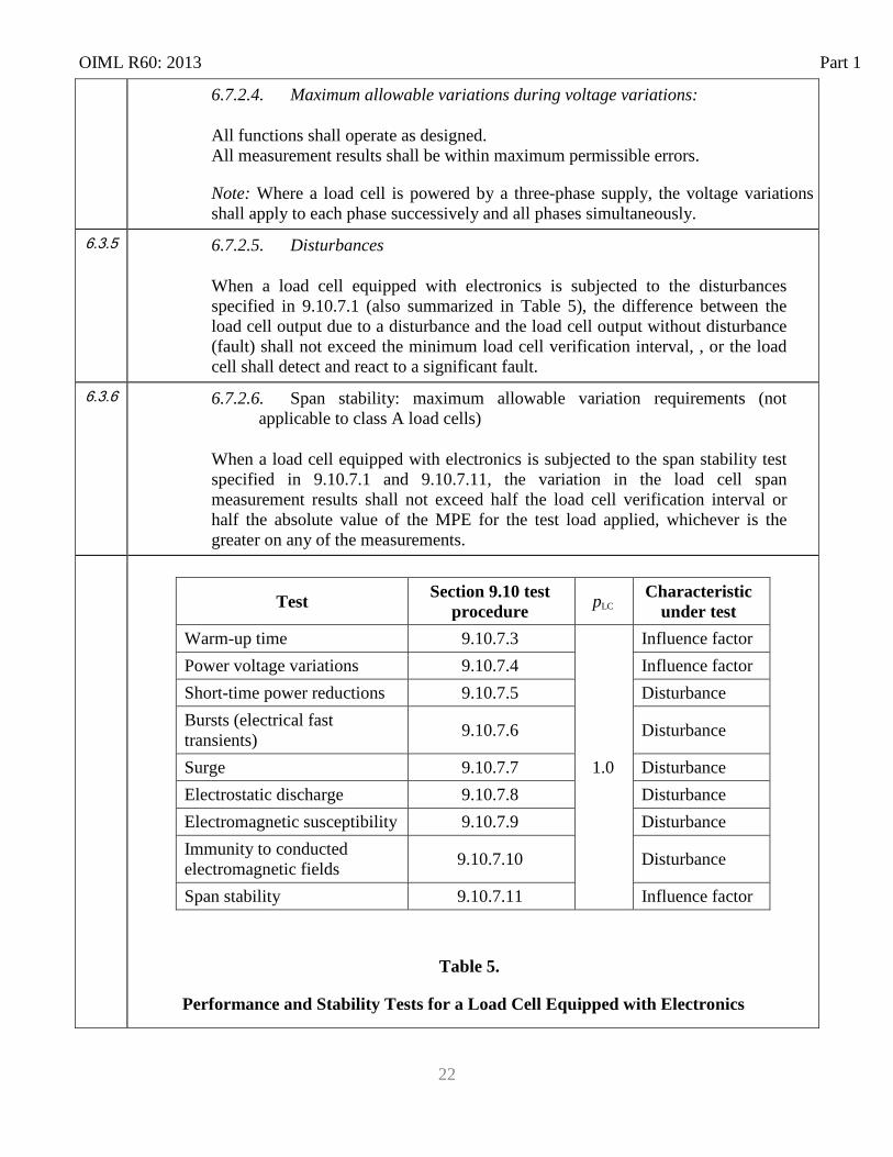
6.7.2.4. Maximum allowable variations during voltage variations:
All functions shall operate as designed. All measurement results shall be within maximum permissible errors.
Note: Where a load cell is powered by a three-phase supply, the voltage variations shall apply to each phase successively and all phases simultaneously.
6.3.5
6.7.2.5. Disturbances
When a load cell equipped with electronics is subjected to the disturbances specified in 9.10.7.1 (also summarized in Table 5), the difference between the load cell output due to a disturbance and the load cell output without disturbance (fault) shall not exceed the minimum load cell verification interval, , or the load cell shall detect and react to a significant fault.
6.3.6 6.7.2.6. Span stability: maximum allowable variation requirements (not applicable to class A load cells)
When a load cell equipped with electronics is subjected to the span stability test specified in 9.10.7.1 and 9.10.7.11, the variation in the load cell span measurement results shall not exceed half the load cell verification interval or half the absolute value of the MPE for the test load applied, whichever is the greater on any of the measurements.
Table 5.
Performance and Stability Tests for a Load Cell Equipped with Electronics
Test Section 9.10 test procedure pLC Characteristic
under test Warm-up time 9.10.7.3
1.0
Influence factor Power voltage variations 9.10.7.4 Influence factor Short-time power reductions 9.10.7.5 Disturbance Bursts (electrical fast transients) 9.10.7.6 Disturbance
Surge 9.10.7.7 Disturbance Electrostatic discharge 9.10.7.8 Disturbance Electromagnetic susceptibility 9.10.7.9 Disturbance Immunity to conducted electromagnetic fields 9.10.7.10 Disturbance
Span stability 9.10.7.11 Influence factor
Part 1 OIML R60: 2013
23
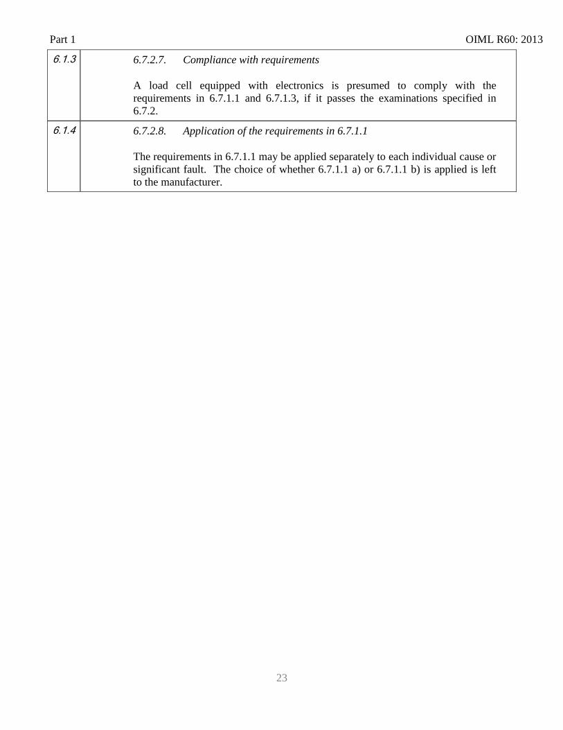
6.1.3 6.7.2.7. Compliance with requirements
A load cell equipped with electronics is presumed to comply with the requirements in 6.7.1.1 and 6.7.1.3, if it passes the examinations specified in 6.7.2.
6.1.4 6.7.2.8. Application of the requirements in 6.7.1.1
The requirements in 6.7.1.1 may be applied separately to each individual cause or significant fault. The choice of whether 6.7.1.1 a) or 6.7.1.1 b) is applied is left to the manufacturer.
OIML R60: 2013 Part 1
24
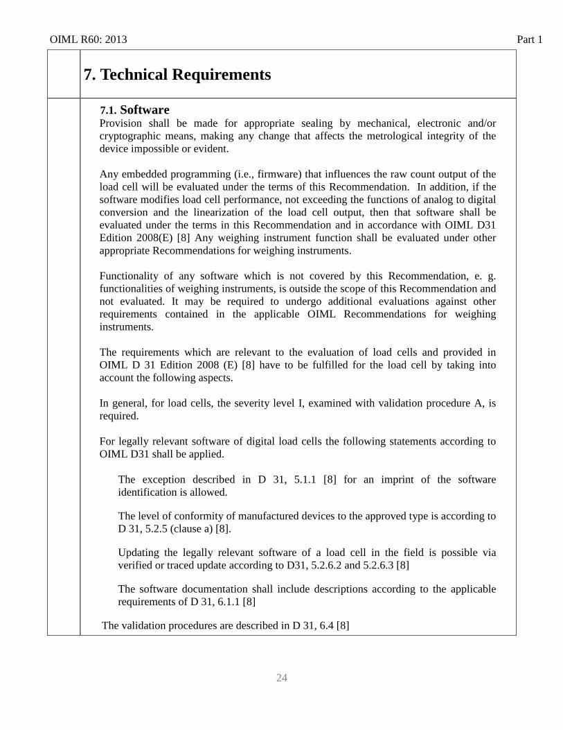
7. Technical Requirements
7.1. Software Provision shall be made for appropriate sealing by mechanical, electronic and/or cryptographic means, making any change that affects the metrological integrity of the device impossible or evident. Any embedded programming (i.e., firmware) that influences the raw count output of the load cell will be evaluated under the terms of this Recommendation. In addition, if the software modifies load cell performance, not exceeding the functions of analog to digital conversion and the linearization of the load cell output, then that software shall be evaluated under the terms in this Recommendation and in accordance with OIML D31 Edition 2008(E) [8] Any weighing instrument function shall be evaluated under other appropriate Recommendations for weighing instruments. Functionality of any software which is not covered by this Recommendation, e. g. functionalities of weighing instruments, is outside the scope of this Recommendation and not evaluated. It may be required to undergo additional evaluations against other requirements contained in the applicable OIML Recommendations for weighing instruments. The requirements which are relevant to the evaluation of load cells and provided in OIML D 31 Edition 2008 (E) [8] have to be fulfilled for the load cell by taking into account the following aspects. In general, for load cells, the severity level I, examined with validation procedure A, is required. For legally relevant software of digital load cells the following statements according to OIML D31 shall be applied.
The exception described in D 31, 5.1.1 [8] for an imprint of the software identification is allowed.
The level of conformity of manufactured devices to the approved type is according to D 31, 5.2.5 (clause a) [8].
Updating the legally relevant software of a load cell in the field is possible via verified or traced update according to D31, 5.2.6.2 and 5.2.6.3 [8]
The software documentation shall include descriptions according to the applicable requirements of D 31, 6.1.1 [8]
The validation procedures are described in D 31, 6.4 [8]
Part 1 OIML R60: 2013
25
4.7
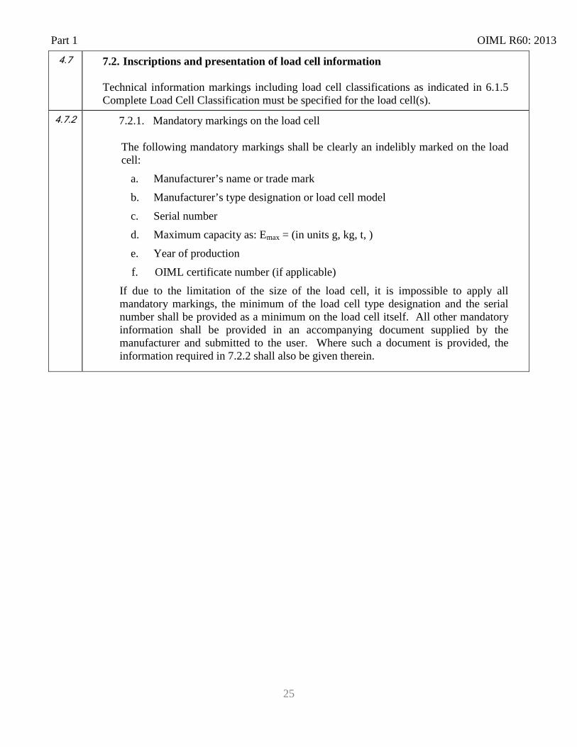
7.2. Inscriptions and presentation of load cell information
Technical information markings including load cell classifications as indicated in 6.1.5 Complete Load Cell Classification must be specified for the load cell(s).
4.7.2 7.2.1. Mandatory markings on the load cell
The following mandatory markings shall be clearly an indelibly marked on the load cell:
a. Manufacturer’s name or trade mark b. Manufacturer’s type designation or load cell model c. Serial number d. Maximum capacity as: Emax = (in units g, kg, t, ) e. Year of production f. OIML certificate number (if applicable)
If due to the limitation of the size of the load cell, it is impossible to apply all mandatory markings, the minimum of the load cell type designation and the serial number shall be provided as a minimum on the load cell itself. All other mandatory information shall be provided in an accompanying document supplied by the manufacturer and submitted to the user. Where such a document is provided, the information required in 7.2.2 shall also be given therein.
OIML R60: 2013 Part 1
26
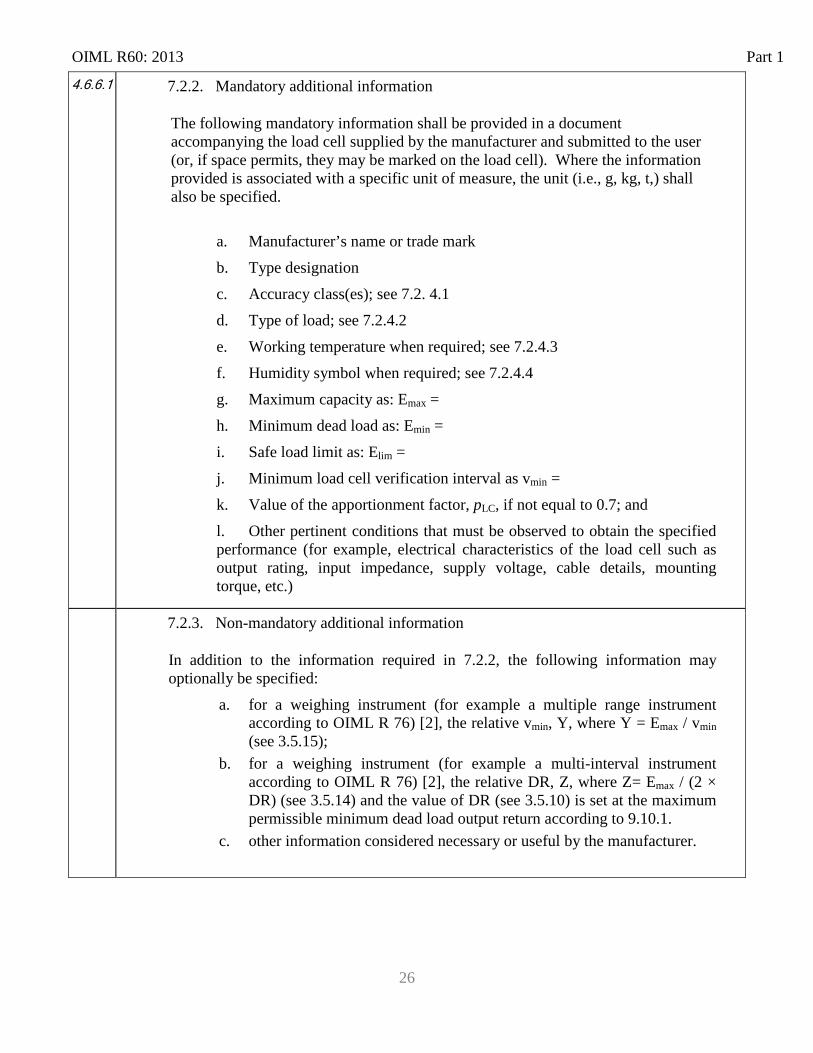
4.6.6.1 7.2.2. Mandatory additional information
The following mandatory information shall be provided in a document accompanying the load cell supplied by the manufacturer and submitted to the user (or, if space permits, they may be marked on the load cell). Where the information provided is associated with a specific unit of measure, the unit (i.e., g, kg, t,) shall also be specified.
a. Manufacturer’s name or trade mark b. Type designation c. Accuracy class(es); see 7.2. 4.1 d. Type of load; see 7.2.4.2 e. Working temperature when required; see 7.2.4.3 f. Humidity symbol when required; see 7.2.4.4 g. Maximum capacity as: Emax = h. Minimum dead load as: Emin = i. Safe load limit as: Elim = j. Minimum load cell verification interval as vmin = k. Value of the apportionment factor, pLC, if not equal to 0.7; and l. Other pertinent conditions that must be observed to obtain the specified performance (for example, electrical characteristics of the load cell such as output rating, input impedance, supply voltage, cable details, mounting torque, etc.)
7.2.3. Non-mandatory additional information
In addition to the information required in 7.2.2, the following information may optionally be specified:
a. for a weighing instrument (for example a multiple range instrument according to OIML R 76) [2], the relative vmin, Y, where Y = Emax / vmin (see 3.5.15);
b. for a weighing instrument (for example a multi-interval instrument according to OIML R 76) [2], the relative DR, Z, where Z= Emax / (2 × DR) (see 3.5.14) and the value of DR (see 3.5.10) is set at the maximum permissible minimum dead load output return according to 9.10.1.
c. other information considered necessary or useful by the manufacturer.
Part 1 OIML R60: 2013
27
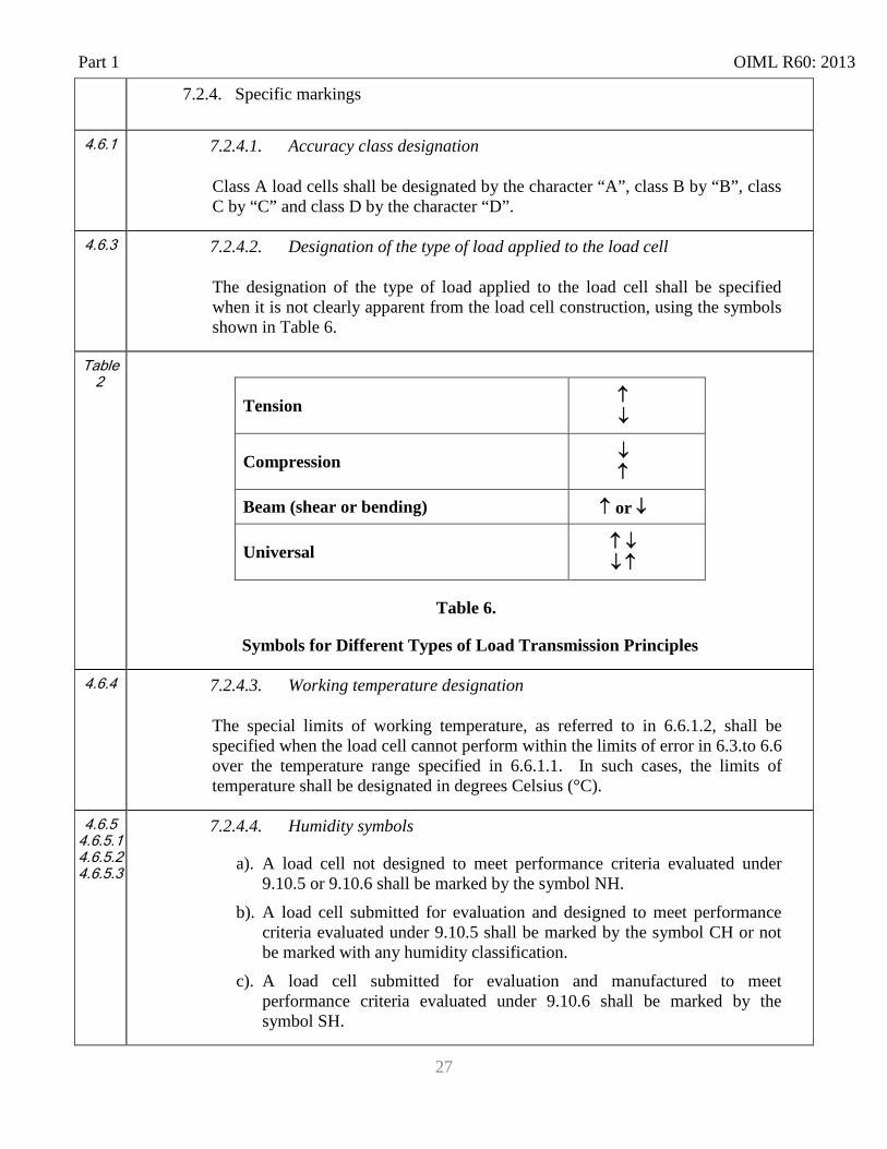
7.2.4. Specific markings
4.6.1
7.2.4.1. Accuracy class designation
Class A load cells shall be designated by the character “A”, class B by “B”, class C by “C” and class D by the character “D”.
4.6.3 7.2.4.2. Designation of the type of load applied to the load cell
The designation of the type of load applied to the load cell shall be specified when it is not clearly apparent from the load cell construction, using the symbols shown in Table 6.
Table 2
Tension ↑ ↓
Compression ↓ ↑
Beam (shear or bending) ↑ or ↓
Universal ↑ ↓ ↓ ↑
Table 6.
Symbols for Different Types of Load Transmission Principles
4.6.4 7.2.4.3. Working temperature designation
The special limits of working temperature, as referred to in 6.6.1.2, shall be specified when the load cell cannot perform within the limits of error in 6.3.to 6.6 over the temperature range specified in 6.6.1.1. In such cases, the limits of temperature shall be designated in degrees Celsius (°C).
4.6.5 4.6.5.1 4.6.5.2 4.6.5.3
7.2.4.4. Humidity symbols
a). A load cell not designed to meet performance criteria evaluated under 9.10.5 or 9.10.6 shall be marked by the symbol NH.
b). A load cell submitted for evaluation and designed to meet performance criteria evaluated under 9.10.5 shall be marked by the symbol CH or not be marked with any humidity classification.
c). A load cell submitted for evaluation and manufactured to meet performance criteria evaluated under 9.10.6 shall be marked by the symbol SH.
OIML R60: 2013 Part 1
28
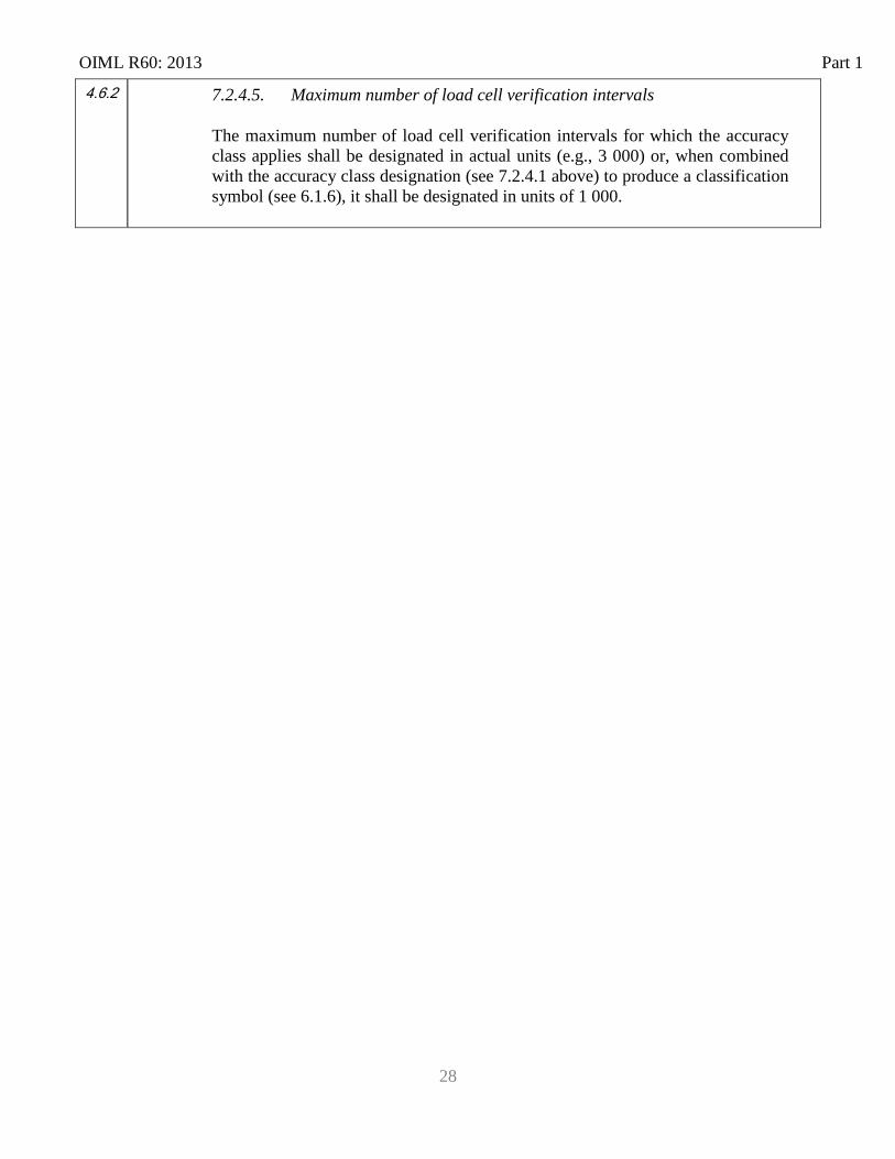
4.6.2 7.2.4.5. Maximum number of load cell verification intervals
The maximum number of load cell verification intervals for which the accuracy class applies shall be designated in actual units (e.g., 3 000) or, when combined with the accuracy class designation (see 7.2.4.1 above) to produce a classification symbol (see 6.1.6), it shall be designated in units of 1 000.

OIML R60: 2012 Part 2
Part 2 Metrological controls and performance tests 7 8 Metrological controls
7.1 8.1 Liability to legal metrological controls
7.1.1
8.1.1 Imposition of controls
This Recommendation prescribes performance requirements for load cells used in devices or systems subjected to legal metrological control. National legislation may impose metrological controls that verify compliance with this Recommendation. Such controls, when imposed, may include type evaluation.
8.2 Responsibility for compliance with the requirements
Notwithstanding the kind of legal metrological control in a country, the manufacturer (or their formal representative) has the full responsibility that the load cells comply with the requirements in Part 1 (Metrological and technical requirements) and are in accordance with the certificate issued for the load cell’s type approval at the moment they are delivered to the user. After assignment, the responsibility of compliance with the requirements in Part 1 (Metrological and technical requirements) is that of the owner of the load cell as long as the load cell is in use. The operational presence of the load cell in his premises is considered as “in use”.
5.6 8.1.2 Measurement standards
The expanded uncertainty, U (for coverage factor k = 2), for the combination of the force-generating system and the indicating instrument used during the tests to observe the load cell output shall be less than 1/3 times the MPE of the load cell under test. [Guide to the Expression of Uncertainty in Measurement, 2008] [7]
Annex A 9 Type evaluation
A.1 9.1 Scope
This section provides test procedures for type evaluation testing of load cells.
Wherever possible, test procedures have been established to apply as broadly as possible to all load cells within the scope of OIML R 60.
The procedures apply to the testing of load cells only. No attempt has been made to cover testing of complete systems that include load cells.
Part 2 OIML R60: 2013
31
7.2 9.2 Test requirements
Test procedures for the type evaluation of load cells are provided in Section 9 and the Test Report Format is provided in Part 3. Initial and subsequent verification of load cells independent of the measuring system in which they are used is normally considered inappropriate if the complete system performance is verified by other means.
9.3 Selection of specimens for evaluation Type evaluation shall be carried out on at least one specimen, which represents the type. The evaluation shall consist of the examination and tests specified in 9.6 and 9.7
In case the applicant wants to have approved several versions or measuring ranges, the issuing authority decides which version(s) and range(s) shall be supplied.
If a specimen does not pass a specific test as a result of the design of the type and therefore has to be modified, the applicant shall carry out this modification to all the specimens supplied for test. If the modification has been applied to all sub-types of the family which have the common design defect that required modification, it is then required that the other specimens that have been submitted shall be completely tested.
If during the evaluation the specimen experiences malfunction or breakage that necessitates a repair in order to complete the test, the applicant shall verify whether this repair concerns an incident or whether a modification will need be made to the design. In the latter case the modification is to be applied to all specimens supplied for the test and the applicable documentation to be updated accordingly.
If the issuing authority has reason to believe that a modification or repair could cause a different outcome for test result(s) than the result(s) which was observed prior to any modification, these tests shall be repeated. The reason for repeating a test shall be given within the scope of the test report.
7.3.1 9.3.1 Number of load cells to be tested
The selection of load cells to be tested shall be such that the number of load cells to be tested is minimized as well as optimized. (see practical example in Annex D).
OIML R60: 2013 Part 2
32
7.3
9.4 Selection of load cells within a family
In order to accelerate the test procedure, the testing laboratory may carry out different tests simultaneously on different units. In this case, the issuing authority decides which version or measuring range will be subjected to a specific test.
All accuracy and influence tests including span stability test for digital load cells, shall be performed on the same unit. Disturbance tests on digital load cells may be (simultaneously) carried out on not more than 2 an additional load cell instruments.
Where a family composed of one or more groups of load cells of various capacities and characteristics is presented for type evaluation, the following provisions shall apply.
7.3.2 9.4.1 Load cells of the same capacity belonging to different groups
Where load cells of the same family and same capacity belong to different groups, the selection of a load cell for testing requires a choice between characteristics of the load cells. In this case, the load cell requiring the most onerous tests shall be selected. This selection will result in the load cell with the most stringent metrological characteristics being tested.
7.3.3 9.4.2 Load cells with a capacity in between the capacities tested
Load cells of the same family with a capacity in between the capacities tested, as well as those above the largest capacity tested, but not over 5 times above the largest capacity tested, are deemed to fulfill the requirements of this Recommendation. This is under the provision that along with the change of capacity there is no change of measurement principle or material used in construction of the load cell (e.g., from bending beam to shear beam or stainless steel replacing aluminum).
7.3.4 9.4.3 Smallest capacity load cell from the group
For any family, the smallest capacity load cell from the group with the best characteristics shall be selected for testing. For any group, the smallest capacity load cell in the group shall always be selected for test unless that capacity falls within the range of allowed capacities of selected load cells having better metrological characteristics according to the requirements of 9.4.2 and 9.4.3.
7.3.5 9.4.4 Ratio of largest capacity to the nearest smaller capacity
When the ratio of the largest capacity load cell in each group to the nearest smaller capacity having been selected for test is greater than 5, then another load cell shall be selected. The selected load cell shall have a capacity between 5 and 10 times that of the nearest smaller capacity load cell which has been selected. When no capacity meets this criterion, the selected load cell shall be that having the smallest capacity exceeding 10 times that of the nearest smaller capacity load cell which has been selected.
Part 2 OIML R60: 2013
33
7.3.6 9.4.5 Humidity test
If more than one load cell of a family has been submitted for testing, only one load cell shall be tested for humidity when applicable.
9.4.6 Selection of load cells equipped with electronics
For load cells and load cell families equipped with electronics and with an analog to digital converter (that do not differ between load cells in the family) all applicable tests shall be performed on the load cell with the minimum, μV/vmin as input for the analog to digital converter.
(Same principle as OIML R76 [2], Annex C, Table 12) Notwithstanding this requirement, the criteria for assignment of a load cell to a family and the selection of test specimens found in 9.4.1 to 9.4.5 shall be observed.
9.5 Documentation
The documentation submitted with the application for type approval shall include:
a) description of its general principle of measurement; b) mechanical drawings (including documents on the load transmission(s) as per
Annex E); c) electric/electronic diagrams; d) installation requirements (physical and electrical) if appropriate; e) operating instructions that shall be provided to the user if appropriate; f) documents or other evidence to support and demonstrate the manufacturer’s belief
that the design and characteristics of the load cell will comply with the requirements of this Recommendation; and
g) documentation relative to software if appropriate.
If the testing laboratory deems this necessary, it can require more detailed documentation; either to be able to study the quality of the instrument, or to be able to fully define the approved type, or both. If the manufacturer does not prescribe a specific load transmission it will be the responsibility of the test laboratory to decide what kind of load transmission is to be used for testing. (see also Annex E)
OIML R60: 2013 Part 2
34
9.6 Examinations Examinations and testing of load cells are intended to verify compliance with the requirements of Part 1 of this Recommendation. The load cell and the documentation shall be given a visual inspection to obtain a general appraisal of its design and construction and the documentation shall be studied.
In particular, the following aspects shall be examined: a. accuracy classes and their symbols (6.1.1 and 7.2.4.1); b. maximum number of load cell verification intervals (6.1.2 and 7.2.4.5); c. load cell measuring ranges (6.2); d. apportioning of errors (6.3.1.1 and 3.7.2); e. construction of load cells (3.3); f. software (7.1) (if applicable); g. inscriptions and presentation of load cell information (7.2); and h. installation instructions/recommendations.
A.3 9.7 Performance Tests
A.2 9.7.1 Purpose
The following test procedures for quantitative determination of load cell performance characteristics are established to ensure uniform type evaluation.
A.3.1 9.7.2 Test equipment
The basic equipment for type evaluation tests consists of a force-generating system and a suitable indicating instrument, which measures the output of the load cell (see 8.1.2).
9.7.3 Test conditions
Part 2 OIML R60: 2013
35
A.3.2.2 9.7.3.1. Environmental conditions
Tests shall be performed under stable environmental conditions. The ambient temperature is deemed to be stable when the difference between extreme temperatures noted during the test does not exceed one fifth of the temperature range of the load cell under test, without being greater than 2 °C. During routine testing, some ambient conditions may not be actively measured or closely controlled unless they are specific parameters for which the load cell is being evaluated. In general, temperature, humidity, and barometric pressure are rigidly controlled under laboratory protocol. Conditions involving: electrical power supplies; electromagnetic fields; and radio frequency fields are to be measured/controlled when the load cell is being evaluated against the effects of these influences, and must also be considered when there is a potential for these types of conditions to impart effects on other tests.
A.3.2.1 9.7.3.2. Acceleration of gravity
The mass standards used to generate the force applied during testing shall be corrected, if necessary, for the site of testing and the value of the gravity constant, g, at the test site shall be recorded with the test results. The value of the mass standards used to generate the force shall be traceable to the appropriate national or international standard of mass.
A.3.2.3 9.7.3.3. Loading conditions
Particular attention shall be paid to loading conditions to prevent the introduction of errors not inherent to the load cell. Factors such as surface roughness, flatness, corrosion, scratches, eccentricity, etc., should be taken into consideration. Loading conditions shall be in accordance with the requirements of the load cell manufacturer. The loads shall be applied and removed along the sensitive axis of the load cell without introducing shock to the load cell. Since the aim of this test is not to measure the influence on the metrological performances of mounting/dismounting the load cell on/from the force-generating system, the installation of the load cell in the force-generating system shall be done with particular care. The effect on the metrological performance caused by mounting/dismounting the load cell on/from the force-generating system should be negligible in order to establish the magnitude of the test parameter. If possible, the load cell should not be dismounted from the force-generation system during the entire period of the test.
A.3.2.4 9.7.3.4. Measuring range limits
With consideration to the capability of the force-generating system, the minimum load, Dmin, shall be as near as possible to but not less than the minimum dead load, Emin, and shall not be higher than a value equal to 10% of Emax. The maximum load, Dmax, shall be not less than 90 % of Emax, nor shall it be greater than Emax (refer to Fig. 3).
OIML R60: 2013 Part 2
36
A.3.2.5 9.7.3.5. Reference standards
All standards and measuring instruments used for the tests shall be traceable to national or international standards.
A.3.2.6 9.7.3.6. Stabilization period
A stabilization period for the load cell under test and the indicating instrument shall be provided, as recommended by the manufacturers of the equipment used.
A.3.2.7 9.7.3.7. Temperature conditions
It is important to allow sufficient time for temperature stabilization of the load cell to be achieved. Particular attention shall be devoted to this requirement for large load cells. The loading system shall be of a design which will not introduce significant thermal gradients within the load cell. The load cell and its connecting means (cables, tubes, etc.) which are integral or contiguous shall be at the same test temperature. The indicating instrument shall be maintained at room temperature. The temperature effect on auxiliary connecting means shall be considered in determining results.
A.3.2.8 9.7.3.8. Barometric pressure effects
Where changes in barometric pressure may significantly affect the load cell output, such changes shall be considered.
9.7.3.9. Humidity effects
When a load cell is marked with the symbol CH or is not marked with a humidity symbol, it shall be subjected to the humidity test, as specified in 9.10.5.
When a load cell is marked with the symbol SH, it shall be subjected to the humidity test, as specified in 9.10.6
Load cells marked with the symbol NH shall not be subjected to the humidity tests as described in 9.10.5 and 9.10.6.
A.3.2.10 9.7.3.10. Indicating instrument checking
Some indicating instruments are provided with a convenient means for checking the indicating instrument itself. When such features are provided, they shall be utilized frequently to ensure that the indicating instrument is within the accuracy required by the test being performed. Periodic check on calibration status of the indicating instrument shall be performed.
Part 2 OIML R60: 2013
37
A.3.2.11 9.7.3.11. Other conditions
Other conditions specified by the manufacturer such as input/output voltage, electrical sensitivity, input impedance of the indicator, etc. shall be taken into consideration during the test.
A.3.2.12 9.7.3.12. Time and date format
All time and date points shall be recorded such that the data can later be presented in test reports in absolute, not relative, units of local time and date. The date shall be recorded in the ISO 8601 [9] (Representation of dates and times) format of ccyy-mm-dd. Note: “cc” may be omitted in cases where there is no possible confusion as to the century.
13.4.2 9.7.4 Error under rated operating conditions
The type of load cell is presumed to comply with the provisions specified in 6.3 to 6.5 of this Recommendation, if it passes the tests (9.10), confirming that the error of the measuring instrument does not exceed the maximum permissible error specified in 6.3.1 under the reference conditions in 9.7.3.
5.2 9.8 Rules concerning the determination of errors
5.2.1 9.8.1 Conditions
The limits of error shown in Table 4 shall apply to all load cell measuring ranges complying with the following conditions: n ≤ nmax v ≥ vmin
5.2.2 9.8.2 Limits of error
The limits of error shown in Table 4 shall refer to the error envelope defined in 2.2 and 6.3.1.1 which is referenced to the straight line that passes through the minimum load output and the load cell output for a load of 75 % of the measuring range taken on ascending load at 20 °C. This is based upon the initial 20 °C load test. See Part 3 (Test Report Format for Type Evaluation).
5.2.3 9.8.3 Initial readings
During the conduct of the tests, the initial reading shall be taken at a time interval after the initiation of loading or unloading, whichever is applicable, as specified in Table 8.
OIML R60: 2013 Part 2
38
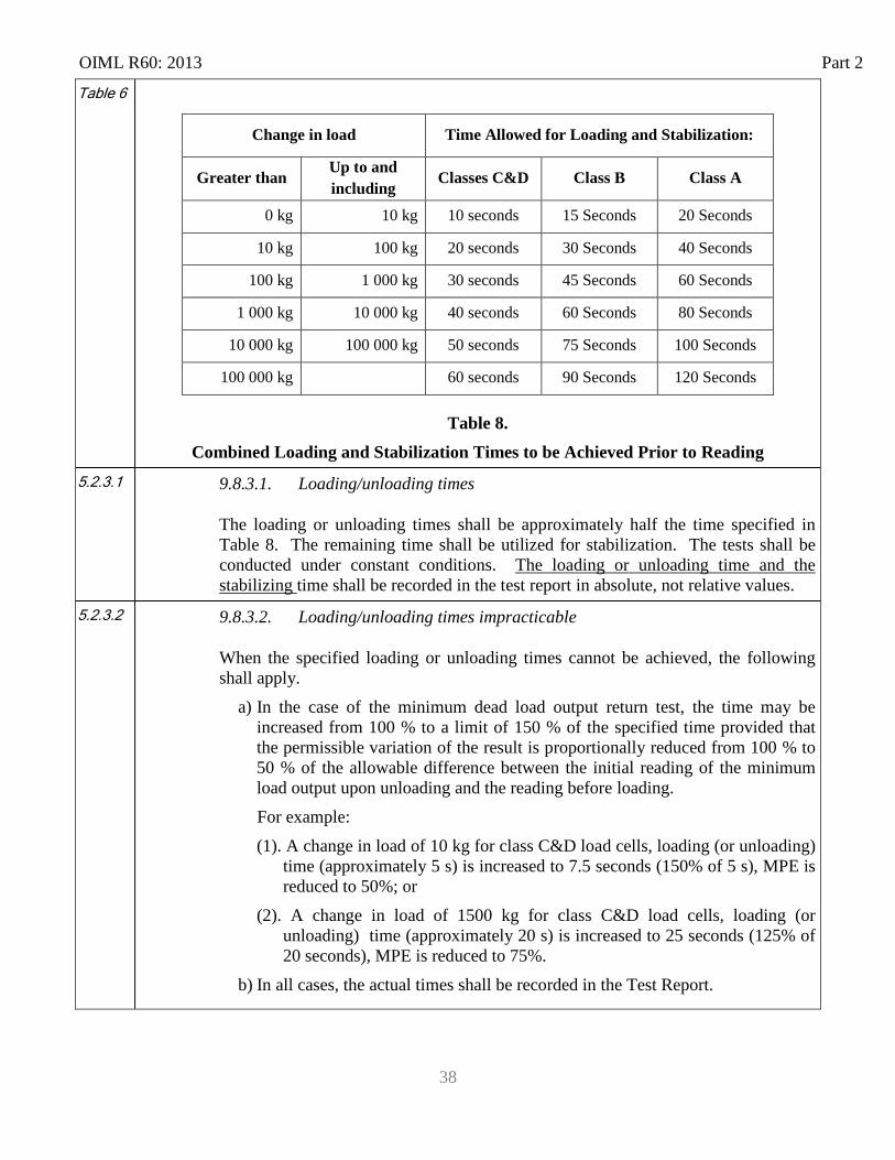
Table 6
Change in load Time Allowed for Loading and Stabilization:
Greater than Up to and including
Classes C&D Class B Class A
0 kg 10 kg 10 seconds 15 Seconds 20 Seconds
10 kg 100 kg 20 seconds 30 Seconds 40 Seconds
100 kg 1 000 kg 30 seconds 45 Seconds 60 Seconds
1 000 kg 10 000 kg 40 seconds 60 Seconds 80 Seconds
10 000 kg 100 000 kg 50 seconds 75 Seconds 100 Seconds
100 000 kg 60 seconds 90 Seconds 120 Seconds
Table 8. Combined Loading and Stabilization Times to be Achieved Prior to Reading
5.2.3.1 9.8.3.1. Loading/unloading times
The loading or unloading times shall be approximately half the time specified in Table 8. The remaining time shall be utilized for stabilization. The tests shall be conducted under constant conditions. The loading or unloading time and the stabilizing time shall be recorded in the test report in absolute, not relative values.
5.2.3.2 9.8.3.2. Loading/unloading times impracticable
When the specified loading or unloading times cannot be achieved, the following shall apply.
a) In the case of the minimum dead load output return test, the time may be increased from 100 % to a limit of 150 % of the specified time provided that the permissible variation of the result is proportionally reduced from 100 % to 50 % of the allowable difference between the initial reading of the minimum load output upon unloading and the reading before loading. For example: (1). A change in load of 10 kg for class C&D load cells, loading (or unloading)
time (approximately 5 s) is increased to 7.5 seconds (150% of 5 s), MPE is reduced to 50%; or
(2). A change in load of 1500 kg for class C&D load cells, loading (or unloading) time (approximately 20 s) is increased to 25 seconds (125% of 20 seconds), MPE is reduced to 75%.
b) In all cases, the actual times shall be recorded in the Test Report.
Part 2 OIML R60: 2013
39
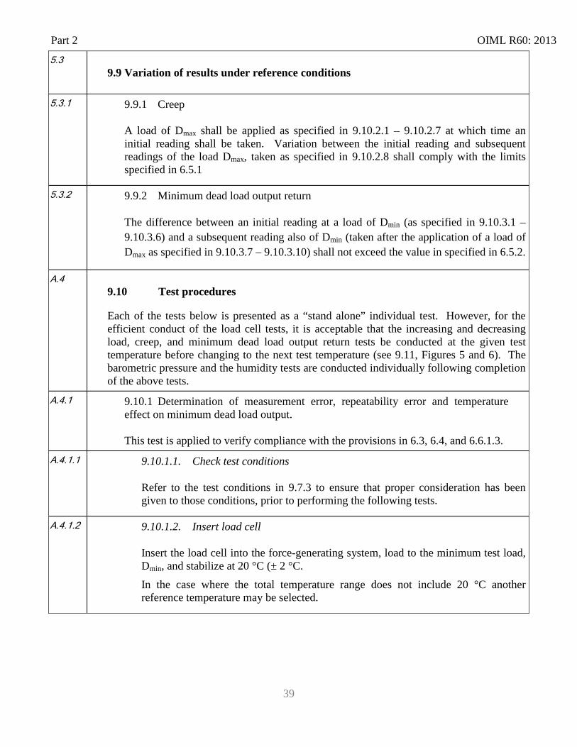
5.3 9.9 Variation of results under reference conditions
5.3.1 9.9.1 Creep
A load of Dmax shall be applied as specified in 9.10.2.1 – 9.10.2.7 at which time an initial reading shall be taken. Variation between the initial reading and subsequent readings of the load Dmax, taken as specified in 9.10.2.8 shall comply with the limits specified in 6.5.1
5.3.2 9.9.2 Minimum dead load output return
The difference between an initial reading at a load of Dmin (as specified in 9.10.3.1 – 9.10.3.6) and a subsequent reading also of Dmin (taken after the application of a load of Dmax as specified in 9.10.3.7 – 9.10.3.10) shall not exceed the value in specified in 6.5.2.
A.4 9.10 Test procedures
Each of the tests below is presented as a “stand alone” individual test. However, for the efficient conduct of the load cell tests, it is acceptable that the increasing and decreasing load, creep, and minimum dead load output return tests be conducted at the given test temperature before changing to the next test temperature (see 9.11, Figures 5 and 6). The barometric pressure and the humidity tests are conducted individually following completion of the above tests.
A.4.1 9.10.1 Determination of measurement error, repeatability error and temperature effect on minimum dead load output.
This test is applied to verify compliance with the provisions in 6.3, 6.4, and 6.6.1.3.
A.4.1.1 9.10.1.1. Check test conditions
Refer to the test conditions in 9.7.3 to ensure that proper consideration has been given to those conditions, prior to performing the following tests.
A.4.1.2 9.10.1.2. Insert load cell
Insert the load cell into the force-generating system, load to the minimum test load, Dmin, and stabilize at 20 °C (± 2 °C. In the case where the total temperature range does not include 20 °C another reference temperature may be selected.
OIML R60: 2013 Part 2
40
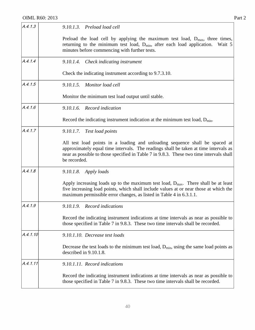
A.4.1.3 9.10.1.3. Preload load cell
Preload the load cell by applying the maximum test load, Dmax, three times, returning to the minimum test load, Dmin, after each load application. Wait 5 minutes before commencing with further tests.
A.4.1.4 9.10.1.4. Check indicating instrument
Check the indicating instrument according to 9.7.3.10.
A.4.1.5 9.10.1.5. Monitor load cell
Monitor the minimum test load output until stable.
A.4.1.6 9.10.1.6. Record indication
Record the indicating instrument indication at the minimum test load, Dmin.
A.4.1.7 9.10.1.7. Test load points
All test load points in a loading and unloading sequence shall be spaced at approximately equal time intervals. The readings shall be taken at time intervals as near as possible to those specified in Table 7 in 9.8.3. These two time intervals shall be recorded.
A.4.1.8 9.10.1.8. Apply loads
Apply increasing loads up to the maximum test load, Dmax. There shall be at least five increasing load points, which shall include values at or near those at which the maximum permissible error changes, as listed in Table 4 in 6.3.1.1.
A.4.1.9 9.10.1.9. Record indications
Record the indicating instrument indications at time intervals as near as possible to those specified in Table 7 in 9.8.3. These two time intervals shall be recorded.
A.4.1.10 9.10.1.10. Decrease test loads
Decrease the test loads to the minimum test load, Dmin, using the same load points as described in 9.10.1.8.
A.4.1.11 9.10.1.11. Record indications
Record the indicating instrument indications at time intervals as near as possible to those specified in Table 7 in 9.8.3. These two time intervals shall be recorded.
Part 2 OIML R60: 2013
41
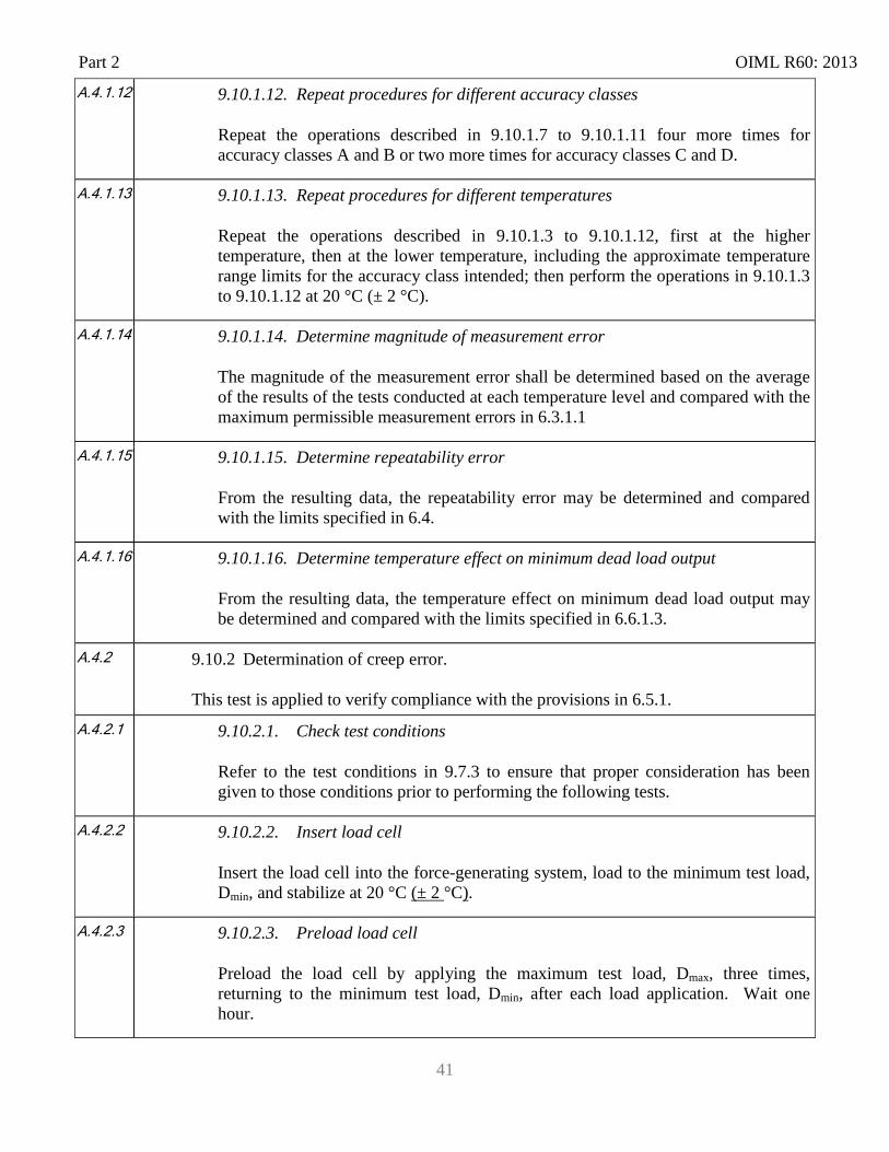
A.4.1.12 9.10.1.12. Repeat procedures for different accuracy classes
Repeat the operations described in 9.10.1.7 to 9.10.1.11 four more times for accuracy classes A and B or two more times for accuracy classes C and D.
A.4.1.13 9.10.1.13. Repeat procedures for different temperatures
Repeat the operations described in 9.10.1.3 to 9.10.1.12, first at the higher temperature, then at the lower temperature, including the approximate temperature range limits for the accuracy class intended; then perform the operations in 9.10.1.3 to 9.10.1.12 at 20 °C (± 2 °C).
A.4.1.14 9.10.1.14. Determine magnitude of measurement error
The magnitude of the measurement error shall be determined based on the average of the results of the tests conducted at each temperature level and compared with the maximum permissible measurement errors in 6.3.1.1
A.4.1.15 9.10.1.15. Determine repeatability error
From the resulting data, the repeatability error may be determined and compared with the limits specified in 6.4.
A.4.1.16 9.10.1.16. Determine temperature effect on minimum dead load output
From the resulting data, the temperature effect on minimum dead load output may be determined and compared with the limits specified in 6.6.1.3.
A.4.2 9.10.2 Determination of creep error.
This test is applied to verify compliance with the provisions in 6.5.1.
A.4.2.1 9.10.2.1. Check test conditions
Refer to the test conditions in 9.7.3 to ensure that proper consideration has been given to those conditions prior to performing the following tests.
A.4.2.2 9.10.2.2. Insert load cell
Insert the load cell into the force-generating system, load to the minimum test load, Dmin, and stabilize at 20 °C (± 2 °C).
A.4.2.3 9.10.2.3. Preload load cell
Preload the load cell by applying the maximum test load, Dmax, three times, returning to the minimum test load, Dmin, after each load application. Wait one hour.
OIML R60: 2013 Part 2
42
A.4.2.4 9.10.2.4. Check indicating instrument
Check the indicating instrument according to 9.7.3.10.
A.4.2.5 9.10.2.5. Monitor load cell
Monitor the minimum test load output until stable.
A.4.2.6 9.10.2.6. Record indication
Record the indicating instrument indication at the minimum test load, Dmin.
A.4.2.7 9.10.2.7. Apply load
Apply a constant maximum test load, Dmax (between 90% and 100% of Emax).
A.4.2.8 9.10.2.8. Record indications
Record the initial indicating instrument indication at the time intervals specified in Table 7 in 9.8.3. Continue to record periodically thereafter, at recorded time intervals over a 30-minute period, ensuring that a reading is taken at 20 minutes.
A.4.2.9 9.10.2.9. Repeat procedures for different temperatures
Repeat the operations described in 9.10.2.3 to 9.10.2.8, first at the higher temperature, then at the lower temperature, including the approximate temperature range limits for the accuracy class intended.
A.4.2.10 9.10.2.10. Determine creep error
With the resulting data, and taking into account the effect of barometric pressure changes according to 9.7.3.7, the magnitude of the creep error can be determined and compared with the permissible variation specified in 6.5.1.
A.4.3 9.10.3 Determination of minimum dead load output return (DR)
This test is applied to verify compliance with the provisions in 6.5.2.
A.4.3.1 9.10.3.1. Check test conditions
Refer to the test conditions in 9.7.3 to ensure that proper consideration has been given to those conditions prior to performing the following test.
A.4.3.2 9.10.3.2. Insert load cell
Insert the load cell into the force-generating system, load to the minimum test load, Dmin, and stabilize at 20 °C (± 2 °C).
Part 2 OIML R60: 2013
43
A.4.3.3 9.10.3.3. Preload load cell
Preload the load cell by applying the maximum test load, Dmax, three times, returning to the minimum test load, Dmin, after each load application. Wait one hour before commencing any further tests.
A.4.3.4 9.10.3.4. Check indicating instrument
Check the indicating instrument according to 9.7.3.10.
A.4.3.5 9.10.3.5. Monitor load cell
Monitor the minimum test load output until stable.
A.4.3.6 9.10.3.6. Record indication
Record the indicating instrument indication at the minimum test load, Dmin.
A.4.3.7 9.10.3.7. Apply load
Apply a constant maximum test load, Dmax (between 90% and 100% of Emax).
A.4.3.8 9.10.3.8. Record indications
Record the initial indicating instrument indication at time intervals as near as possible to those specified in Table 7in 9.8.3. These two time intervals shall be recorded. Record the time at which the load is fully applied and maintain the load for a 30-minute period.
A.4.3.9 9.10.3.9. Record data
Record the time of initiation of unloading and return to the minimum test load, Dmin.
A.4.3.10 9.10.3.10. Record indication
Record the indicating instrument indication at time intervals as near as possible to those specified in Table 7 in 9.8.3. These two time intervals shall be recorded.
A.4.3.11 9.10.3.11. Repeat procedures for different temperatures
Repeat the operations described in 9.10.3.3 to 9.10.3.10, first at the higher temperature, then at the lower temperature, including the approximate temperature range limits for the accuracy class intended.
OIML R60: 2013 Part 2
44
A.4.3.12 9.10.3.12. Determine minimum dead load output return (DR)
With the resulting data, the magnitude of the minimum dead load output return (DR) can be determined and compared with the permissible variation specified in 9.9.2.
A.4.4
9.10.4 Determination of barometric pressure effects (Atmospheric pressure).
This test is applied to verify compliance with the provisions in 6.6.2.
This test shall be conducted unless there is sufficient design justification to show that the load cell performance is not affected by changes in barometric pressure. The justification for not conducting this test shall be noted in the test report.
A.4.4.1
9.10.4.1. Check test conditions
Refer to the test conditions in 9.7.3 to ensure that proper consideration has been given to those conditions prior to performing the following test.
A.4.4.2 9.10.4.2. Insert load cell
At room temperature, insert the unloaded load cell into the pressure chamber at atmospheric pressure.
A.4.4.3
9.10.4.3. Check indicating instrument
Check the indicating instrument according to 9.7.3.10.
A.4.4.4
9.10.4.4. Monitor load cell
Monitor the output until stable.
A.4.4.5 9.10.4.5. Record indication
Record the indicating instrument indication.
A.4.4.6
9.10.4.6. Change barometric pressure
Change the barometric pressure by a minimum of 1 kPa greater than atmospheric pressure and record the indicating instrument indication.
A.4.4.7
9.10.4.7. Determine barometric pressure error
With the resulting data, the magnitude of the barometric pressure influence can be determined and compared with the limits specified in 6.6.2.
A.4.5 9.10.5 Determination of humidity effects for load cells marked CH or not marked.
This test is applied to verify compliance with the provisions in 6.6.3.1.
Part 2 OIML R60: 2013
45
A.4.5.1 9.10.5.1. Check test conditions
Refer to the test conditions in 9.7.3 to ensure that proper consideration has been given to those conditions prior to performing the following test.
A.4.5.2 9.10.5.2. Insert load cell
Insert the load cell into the force-generating system, load to the minimum test load, Dmin, and stabilize at 20 °C (± 2 °C).
A.4.5.3 9.10.5.3. Preload load cell
Preload the load cell by applying the maximum test load, Dmax, three times, returning to the minimum test load, Dmin, after each application. Wait 5 minutes before commencing any further tests.
A.4.5.4 9.10.5.4. Check indicating instrument
Check the indicating instrument according to 9.7.3.10.
A.4.5.5 9.10.5.5. Monitor load cell
Monitor the minimum test load output until stable.
A.4.5.6 9.10.5.6. Record indication
Record the indicating instrument indication at the minimum test load, Dmin.
A.4.5.7 9.10.5.7. Apply load
Apply a maximum test load, Dmax.
A.4.5.8 9.10.5.8. Record indications
Record the initial indicating instrument indication at time intervals as near as possible to those specified in Table 7 in 9.8.3. These two time intervals shall be recorded.
A.4.5.9 9.10.5.9. Remove load
Remove the test load to the minimum test load, Dmin.
A.4.5.10 9.10.5.10. Record indication
Record the indicating instrument indication at time intervals as near as possible to those specified in Table 7 in 9.8.3. These two time intervals shall be recorded.
OIML R60: 2013 Part 2
46
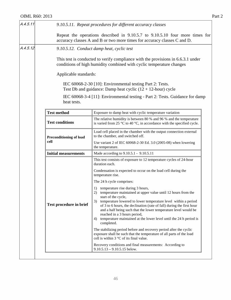
A.4.5.11 9.10.5.11. Repeat procedures for different accuracy classes
Repeat the operations described in 9.10.5.7 to 9.10.5.10 four more times for accuracy classes A and B or two more times for accuracy classes C and D.
A.4.5.12
9.10.5.12. Conduct damp heat, cyclic test
This test is conducted to verify compliance with the provisions in 6.6.3.1 under conditions of high humidity combined with cyclic temperature changes
Applicable standards:
IEC 60068-2-30 [10]: Environmental testing Part 2: Tests. Test Db and guidance: Damp heat cyclic (12 + 12-hour) cycle IEC 60068-3-4 [11]: Environmental testing - Part 2: Tests. Guidance for damp
heat tests.
Test method Exposure to damp heat with cyclic temperature variation
Test conditions The relative humidity is between 80 % and 96 % and the temperature is varied from 25 °C to 40 °C, in accordance with the specified cycle.
Preconditioning of load cell
Load cell placed in the chamber with the output connection external to the chamber, and switched off.
Use variant 2 of IEC 60068-2-30 Ed. 3.0 (2005-08) when lowering the temperature.
Initial measurements Made according to 9.10.5.1 - 9.10.5.11
Test procedure in brief
This test consists of exposure to 12 temperature cycles of 24-hour duration each.
Condensation is expected to occur on the load cell during the temperature rise. The 24 h cycle comprises:
1) temperature rise during 3 hours, 2) temperature maintained at upper value until 12 hours from the
start of the cycle, 3) temperature lowered to lower temperature level within a period
of 3 to 6 hours, the declination (rate of fall) during the first hour and a half being such that the lower temperature level would be reached in a 3 hours period,
4) temperature maintained at the lower level until the 24 h period is completed.
The stabilizing period before and recovery period after the cyclic exposure shall be such that the temperature of all parts of the load cell is within 3 °C of its final value. Recovery conditions and final measurements: According to 9.10.5.13 – 9.10.5.15 below.
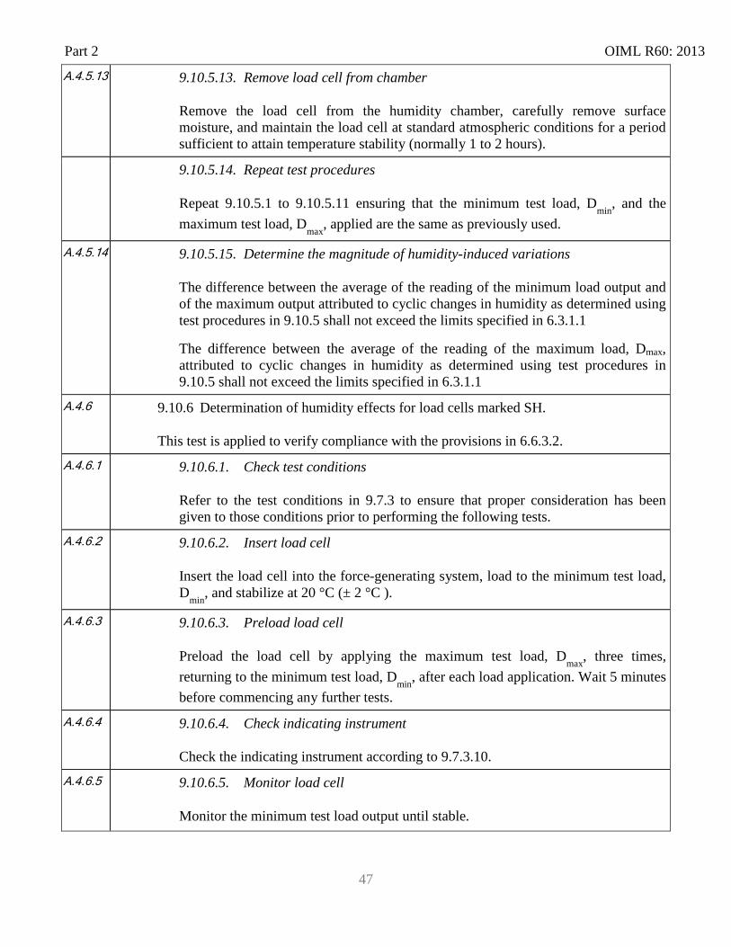
Part 2 OIML R60: 2013
47
A.4.5.13 9.10.5.13. Remove load cell from chamber
Remove the load cell from the humidity chamber, carefully remove surface moisture, and maintain the load cell at standard atmospheric conditions for a period sufficient to attain temperature stability (normally 1 to 2 hours).
9.10.5.14. Repeat test procedures
Repeat 9.10.5.1 to 9.10.5.11 ensuring that the minimum test load, Dmin, and the maximum test load, Dmax, applied are the same as previously used.
A.4.5.14 9.10.5.15. Determine the magnitude of humidity-induced variations
The difference between the average of the reading of the minimum load output and of the maximum output attributed to cyclic changes in humidity as determined using test procedures in 9.10.5 shall not exceed the limits specified in 6.3.1.1
The difference between the average of the reading of the maximum load, Dmax, attributed to cyclic changes in humidity as determined using test procedures in 9.10.5 shall not exceed the limits specified in 6.3.1.1
A.4.6
9.10.6 Determination of humidity effects for load cells marked SH.
This test is applied to verify compliance with the provisions in 6.6.3.2.
A.4.6.1 9.10.6.1. Check test conditions
Refer to the test conditions in 9.7.3 to ensure that proper consideration has been given to those conditions prior to performing the following tests.
A.4.6.2 9.10.6.2. Insert load cell
Insert the load cell into the force-generating system, load to the minimum test load, Dmin, and stabilize at 20 °C (± 2 °C ).
A.4.6.3 9.10.6.3. Preload load cell
Preload the load cell by applying the maximum test load, Dmax, three times, returning to the minimum test load, Dmin, after each load application. Wait 5 minutes before commencing any further tests.
A.4.6.4 9.10.6.4. Check indicating instrument
Check the indicating instrument according to 9.7.3.10.
A.4.6.5 9.10.6.5. Monitor load cell
Monitor the minimum test load output until stable.
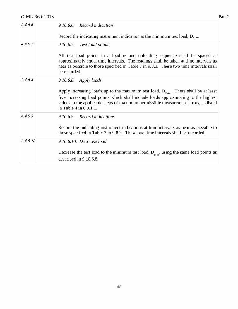
OIML R60: 2013 Part 2
48
A.4.6.6 9.10.6.6. Record indication
Record the indicating instrument indication at the minimum test load, Dmin.
A.4.6.7 9.10.6.7. Test load points
All test load points in a loading and unloading sequence shall be spaced at approximately equal time intervals. The readings shall be taken at time intervals as near as possible to those specified in Table 7 in 9.8.3. These two time intervals shall be recorded.
A.4.6.8 9.10.6.8. Apply loads
Apply increasing loads up to the maximum test load, Dmax. There shall be at least five increasing load points which shall include loads approximating to the highest values in the applicable steps of maximum permissible measurement errors, as listed in Table 4 in 6.3.1.1.
A.4.6.9 9.10.6.9. Record indications
Record the indicating instrument indications at time intervals as near as possible to those specified in Table 7 in 9.8.3. These two time intervals shall be recorded.
A.4.6.10 9.10.6.10. Decrease load
Decrease the test load to the minimum test load, Dmin, using the same load points as described in 9.10.6.8.
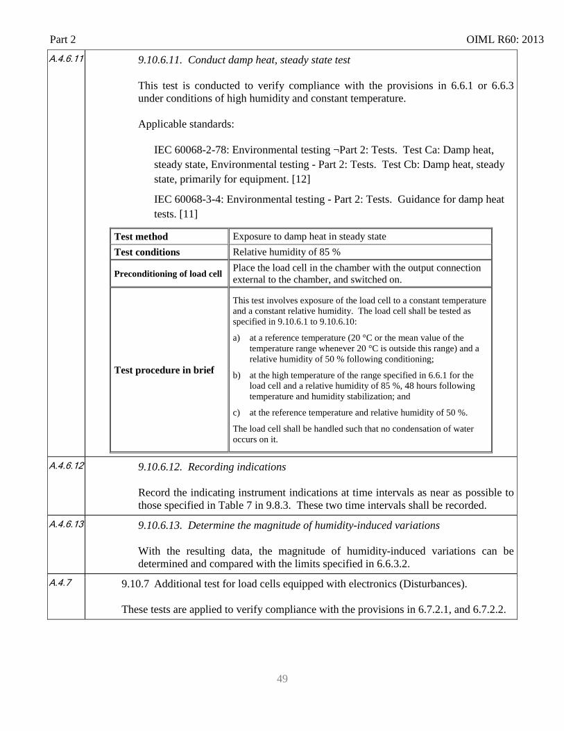
Part 2 OIML R60: 2013
49
A.4.6.11
9.10.6.11. Conduct damp heat, steady state test
This test is conducted to verify compliance with the provisions in 6.6.1 or 6.6.3 under conditions of high humidity and constant temperature.
Applicable standards:
IEC 60068-2-78: Environmental testing ¬Part 2: Tests. Test Ca: Damp heat, steady state, Environmental testing - Part 2: Tests. Test Cb: Damp heat, steady state, primarily for equipment. [12]
IEC 60068-3-4: Environmental testing - Part 2: Tests. Guidance for damp heat tests. [11]
Test method Exposure to damp heat in steady state Test conditions Relative humidity of 85 %
Preconditioning of load cell Place the load cell in the chamber with the output connection external to the chamber, and switched on.
Test procedure in brief
This test involves exposure of the load cell to a constant temperature and a constant relative humidity. The load cell shall be tested as specified in 9.10.6.1 to 9.10.6.10:
a) at a reference temperature (20 °C or the mean value of the temperature range whenever 20 °C is outside this range) and a relative humidity of 50 % following conditioning;
b) at the high temperature of the range specified in 6.6.1 for the load cell and a relative humidity of 85 %, 48 hours following temperature and humidity stabilization; and
c) at the reference temperature and relative humidity of 50 %.
The load cell shall be handled such that no condensation of water occurs on it.
A.4.6.12 9.10.6.12. Recording indications
Record the indicating instrument indications at time intervals as near as possible to those specified in Table 7 in 9.8.3. These two time intervals shall be recorded.
A.4.6.13 9.10.6.13. Determine the magnitude of humidity-induced variations
With the resulting data, the magnitude of humidity-induced variations can be determined and compared with the limits specified in 6.6.3.2.
A.4.7
9.10.7 Additional test for load cells equipped with electronics (Disturbances).
These tests are applied to verify compliance with the provisions in 6.7.2.1, and 6.7.2.2.
OIML R60: 2013 Part 2
50
6.4.1 9.10.7.1. Performance and stability tests
A load cell equipped with electronics shall pass the performance and stability tests according to 9.10.7.2 to 9.10.7.10 for the tests given in Table 5.
A.4.7.1 9.10.7.2. Evaluation of error for digital load cells
For load cells possessing a digital output interval greater than 0.20v, the changeover points are to be used in the evaluation of errors, prior to rounding as follows. At a certain load, L, the digital output value, I, is noted. Additional loads, for example 0.1 v, are successively added until the output of the load cell is increased unambiguously by one digital output increment (I + v). The additional amount of load, Δ L, added to the load cell gives the digital output value prior to rounding, P, by using the following formula: P = I + 1/2 v – Δ L
where:
I = the indication or digital output value; v = the load cell verification interval; and Δ L = additional load added to the load cell.
The error, E, prior to rounding is:
E = P – L = I + 1/2 v – ΔL – L and the corrected error, Ec, prior to rounding is:
Ec = E – Eo ≤ MPE
where Eo is the error calculated at the minimum test load, Dmin.
Part 2 OIML R60: 2013
51
A.4.7.2 9.10.7.3. Warm-up time
Test procedure in brief: Stabilize the load cell at 20 °C (± 2 °C) and disconnect from any electrical supply for a period of at least 8 hours prior to the test. Insert the load cell into the force-generating system. Preload the load cell by applying a maximum test load, Dmax, then, returning to the minimum test load, Dmin, three times. Allow the load cell to rest for 5 minutes. Connect the load cell to the power supply and switch on. Record data: As soon as a measurement result can be obtained, record the minimum test load output and the maximum test load, Dmax, applied.
Loading and unloading: The maximum test load output shall be determined at time intervals as close as possible to those specified in Table 7 in 9.8.3 and recorded and the load should be returned to the minimum test load, Dmin. These measurements shall be repeated after 5, 15 and 30 minutes.
For load cells of class A, the provisions of the operating manual for the time following connection to electrical supply shall be observed.
OIML R60: 2013 Part 2
52
A.4.7.3
9.10.7.4. Power voltage variations
This test is applied to verify compliance with 6.7.2.2, 6.7.2.3, and 6.7.2.4 under conditions of variations in voltage to the load cell’s power supply.
Applicable standards:
For load cells powered by AC mains: IEC/TR3 61000-2-1 [13], IEC 61000-4-1(set-up) [14]
For load cells powered by DC mains: IEC 61000-4-29 [15], IEC 61000-4-1(set-up) [14]
Test method Subject load cell to variations of power supply voltage Test conditions In accordance with 9.7.3.1 Environmental conditions Preconditioning of load cell Stabilize load cell under constant environmental conditions
Test level
Mains power voltage variations*: upper voltage limit (V + 10%); lower voltage limit (V – 15%) Battery power voltage variations: - upper voltage limit (not applicable); - lower power voltage: (specified by the manufacturer, below V) The voltage, (V) is the value specified by the manufacturer. If a range of reference mains power voltage (Vmin, Vmax) is specified, then the test shall be performed at an upper voltage limit of Vmax and a lower voltage limit of Vmin. * Note: Where a load cell is powered by a three-phase supply, the voltage variations shall apply to each phase successively and all phases simultaneously.
Test procedure in brief
This test consists of subjecting the load cell to variations of power voltage. A load test is performed in accordance with 9.10.1.1 to 9.10.1.12 at 20°C (± 2 °C), with the load cell powered at reference voltage. The test is repeated with the load cell powered at the upper limit and at the lower limit of power voltage.
Part 2 OIML R60: 2013
53
6A.4.7.4
9.10.7.5. Short-time power reductions (see 6.7.2.5 Disturbances)
This test is conducted to verify compliance with 6.7.2.2, 6.7.2.3, and 6.7.2.4 under conditions of short-time power reductions
Applicable standards:
For load cells powered by DC mains: IEC 61000-4-29 [15]; IEC 61000-4-1 [14] For load cells powered by AC mains; IEC 61000-4-11 [16]; IEC 61000-6-1 [17];
IEC 61000-6-2 [18]
Test method Expose load cell to specified short-timer power reductions Test conditions In accordance with 9.7.3.1 Environmental conditions
Preconditioning of load cell Stabilize load cell under constant environmental conditions
Test level Reduction: 100 % 50 % Number of half cycles: 1 2
Test procedure in brief
A test generator as defined in the referred standard shall be used. The test generator shall be adjusted before connecting to the load cell. The load cell shall be exposed to short interuptions of power as described in the The mains voltage reductions shall be repeated ten times at intervals of at least 10 seconds.
Notes During the test, the effect of any automatic zero-setting or zero-tracking features (if applicable) shall be switched off or suppressed, for example by applying a small test load. The test load need not be greater than necessary to accomplish this suppression.
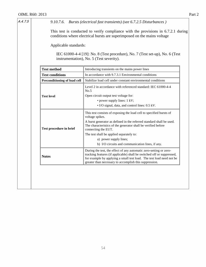
OIML R60: 2013 Part 2
54
A.4.7.5 9.10.7.6. Bursts (electrical fast transients) (see 6.7.2.5 Disturbances )
This test is conducted to verify compliance with the provisions in 6.7.2.1 during conditions where electrical bursts are superimposed on the mains voltage
Applicable standards:
IEC 61000-4-4 [19]: No. 8 (Test procedure), No. 7 (Test set-up), No. 6 (Test instrumentation), No. 5 (Test severity).
Test method Introducing transients on the mains power lines Test conditions In accordance with 9.7.3.1 Environmental conditions Preconditioning of load cell Stabilize load cell under constant environmental conditions
Test level
Level 2 in accordance with referenced standard: IEC 61000-4-4 No.5 Open circuit output test voltage for:
• power supply lines: 1 kV; • I/O signal, data, and control lines: 0.5 kV.
Test procedure in brief
This test consists of exposing the load cell to specified bursts of voltage spikes. A burst generator as defined in the referred standard shall be used. The characteristics of the generator shall be verified before connecting the EUT. The test shall be applied separately to: a) power supply lines; b) I/O circuits and communication lines, if any.
Notes During the test, the effect of any automatic zero-setting or zero-tracking features (if applicable) shall be switched off or suppressed, for example by applying a small test load. The test load need not be greater than necessary to accomplish this suppression.
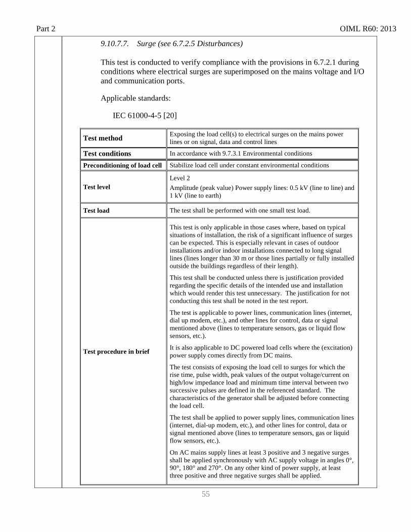
Part 2 OIML R60: 2013
55
9.10.7.7. Surge (see 6.7.2.5 Disturbances)
This test is conducted to verify compliance with the provisions in 6.7.2.1 during conditions where electrical surges are superimposed on the mains voltage and I/O and communication ports.
Applicable standards:
IEC 61000-4-5 [20]
Test method Exposing the load cell(s) to electrical surges on the mains power lines or on signal, data and control lines
Test conditions In accordance with 9.7.3.1 Environmental conditions
Preconditioning of load cell Stabilize load cell under constant environmental conditions
Test level Level 2 Amplitude (peak value) Power supply lines: 0.5 kV (line to line) and 1 kV (line to earth)
Test load The test shall be performed with one small test load.
Test procedure in brief
This test is only applicable in those cases where, based on typical situations of installation, the risk of a significant influence of surges can be expected. This is especially relevant in cases of outdoor installations and/or indoor installations connected to long signal lines (lines longer than 30 m or those lines partially or fully installed outside the buildings regardless of their length).
This test shall be conducted unless there is justification provided regarding the specific details of the intended use and installation which would render this test unnecessary. The justification for not conducting this test shall be noted in the test report.
The test is applicable to power lines, communication lines (internet, dial up modem, etc.), and other lines for control, data or signal mentioned above (lines to temperature sensors, gas or liquid flow sensors, etc.).
It is also applicable to DC powered load cells where the (excitation) power supply comes directly from DC mains.
The test consists of exposing the load cell to surges for which the rise time, pulse width, peak values of the output voltage/current on high/low impedance load and minimum time interval between two successive pulses are defined in the referenced standard. The characteristics of the generator shall be adjusted before connecting the load cell.
The test shall be applied to power supply lines, communication lines (internet, dial-up modem, etc.), and other lines for control, data or signal mentioned above (lines to temperature sensors, gas or liquid flow sensors, etc.).
On AC mains supply lines at least 3 positive and 3 negative surges shall be applied synchronously with AC supply voltage in angles 0°, 90°, 180° and 270°. On any other kind of power supply, at least three positive and three negative surges shall be applied.
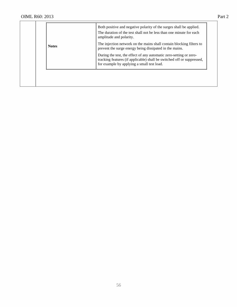
OIML R60: 2013 Part 2
56
Notes
Both positive and negative polarity of the surges shall be applied. The duration of the test shall not be less than one minute for each amplitude and polarity.
The injection network on the mains shall contain blocking filters to prevent the surge energy being dissipated in the mains.
During the test, the effect of any automatic zero-setting or zero-tracking features (if applicable) shall be switched off or suppressed, for example by applying a small test load.
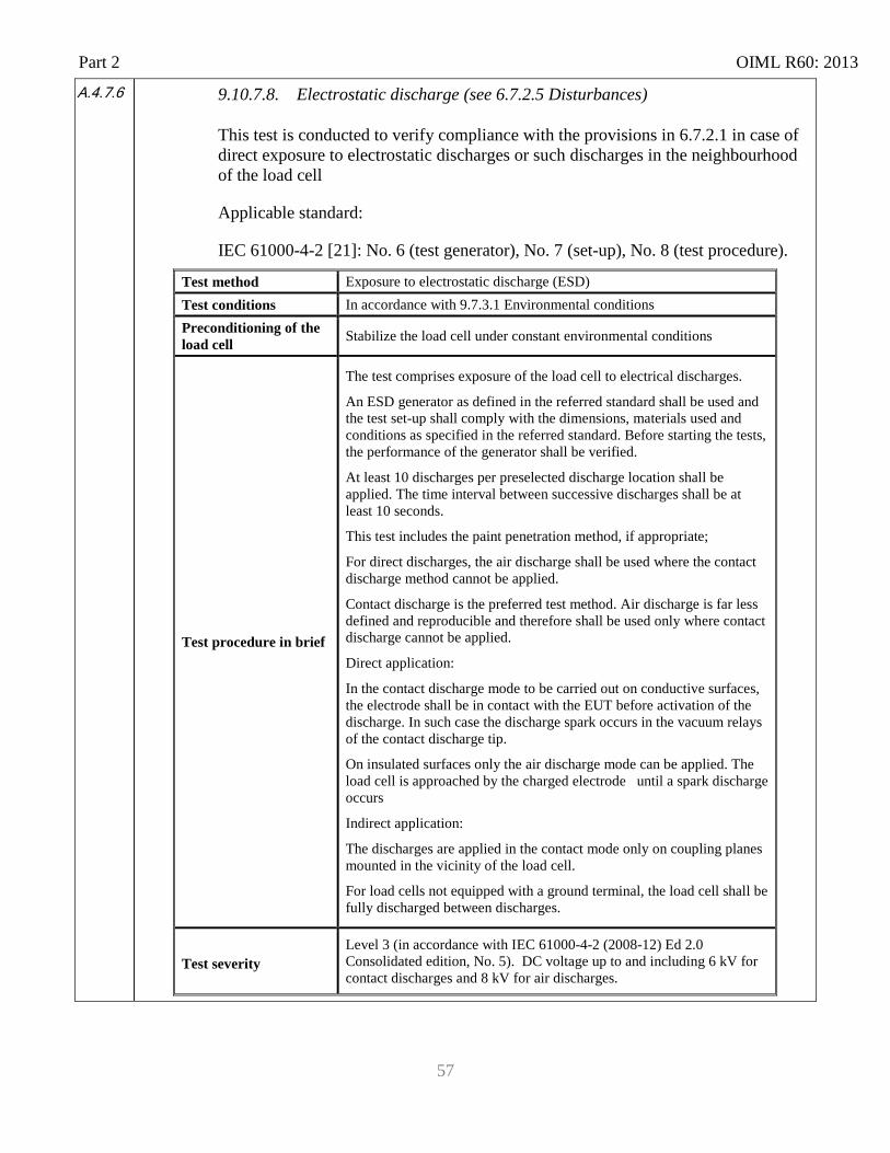
Part 2 OIML R60: 2013
57
A.4.7.6
9.10.7.8. Electrostatic discharge (see 6.7.2.5 Disturbances)
This test is conducted to verify compliance with the provisions in 6.7.2.1 in case of direct exposure to electrostatic discharges or such discharges in the neighbourhood of the load cell
Applicable standard:
IEC 61000-4-2 [21]: No. 6 (test generator), No. 7 (set-up), No. 8 (test procedure).
Test method Exposure to electrostatic discharge (ESD) Test conditions In accordance with 9.7.3.1 Environmental conditions Preconditioning of the load cell Stabilize the load cell under constant environmental conditions
Test procedure in brief
The test comprises exposure of the load cell to electrical discharges.
An ESD generator as defined in the referred standard shall be used and the test set-up shall comply with the dimensions, materials used and conditions as specified in the referred standard. Before starting the tests, the performance of the generator shall be verified.
At least 10 discharges per preselected discharge location shall be applied. The time interval between successive discharges shall be at least 10 seconds.
This test includes the paint penetration method, if appropriate;
For direct discharges, the air discharge shall be used where the contact discharge method cannot be applied.
Contact discharge is the preferred test method. Air discharge is far less defined and reproducible and therefore shall be used only where contact discharge cannot be applied.
Direct application:
In the contact discharge mode to be carried out on conductive surfaces, the electrode shall be in contact with the EUT before activation of the discharge. In such case the discharge spark occurs in the vacuum relays of the contact discharge tip.
On insulated surfaces only the air discharge mode can be applied. The load cell is approached by the charged electrode until a spark discharge occurs
Indirect application:
The discharges are applied in the contact mode only on coupling planes mounted in the vicinity of the load cell.
For load cells not equipped with a ground terminal, the load cell shall be fully discharged between discharges.
Test severity Level 3 (in accordance with IEC 61000-4-2 (2008-12) Ed 2.0 Consolidated edition, No. 5). DC voltage up to and including 6 kV for contact discharges and 8 kV for air discharges.
OIML R60: 2013 Part 2
58
Notes
During the test, the effect of any automatic zero-setting or zero-tracking features shall be switched off or suppressed (if applicable), for example by applying a small test load. The test load applied during this test need not be greater than necessary to accomplish this suppression.
A.4.7.7
9.10.7.9. Electromagnetic susceptibility (see 6.7.2.5 Disturbances)
This test is conducted to verify compliance with the provisions in 6.7.2.1 under conditions of exposure to electromagnetic fields
Applicable standard: IEC 61000-4-3 [22]: No. 6 (test generator), No. 7 (test set-up), No. 8 (test
procedure)
Test method Exposure to specified electromagnetic fields Test conditions In accordance with 9.7.3.1 Environmental conditions Preconditioning of the load cell Stabilize the load cell under constant environmental conditions.
Test procedure in brief
The load cell is exposed to electromagnetic fields with the required field strength and the field uniformity as defined in the referred standard.
The level of field strength specified refers to the field generated by the unmodulated carrier wave.
The load cell shall be exposed to the modulated wave field. The frequency sweep shall be made only pausing to adjust the RF signal level or to switch RF-generators, amplifiers and antennas if necessary. Where the frequency range is swept incrementally, the step size shall not exceed 1 % of the preceding frequency value.
The dwell time of the amplitude modulated carrier at each frequency shall not be less than the time necessary for the load cell to be exercised and to respond, but shall in no case be less than 0.5 s.
Adequate EM fields can be generated in facilities of different type and set-up the use of which is limited by the dimensions of the load cell and the frequency range of the facility.
Test levels
Level 2: Frequency range: 26 MHz to 2 000 MHz; Field strength: 10 V/m; Modulation: 80 % AM, 1 kHz sine wave.
Notes
If test is conducted while load cell is installed as a component in a weighing instrument, then during the test, the effect of any automatic zero-setting or zero-tracking features enabled (if applicable) through the weighing instrument shall be switched off or suppressed, for example by applying a small test load. The test load need not be greater than necessary to accomplish this suppression.
Part 2 OIML R60: 2013
59
9.10.7.10. Immunity to conducted electromagnetic fields (see 6.7.2.5 Disturbances)
This test is conducted to verify compliance with the provisions in 6.7.2.1 while exposed to electromagnetic fields
Applicable standard: IEC 61000-4-6 [23]
Test method Exposure of the the load cell to disturbances induced by radiated radio-frequency fields.
Test conditions In accordance with 9.7.3.1 Environmental conditions Preconditioning of the load cell Stabilize the load cell under constant environmental conditions.
Test procedure in brief
A RF EM current, simulating the influence of EM fields shall be coupled or injected into the power ports and I/O ports of the load cell using coupling/decoupling devices as defined in the referred standard. The characteristics of the test equipment consisting of an RF generator, (de-)coupling devices, attenuators, etc. shall be verified before connecting the load cell.
Test load The test shall be performed with one small test load only.
Test level index
Level 2 (in accordance with the referred standard)
Frequency range: 0.15 MHz-80 MHz RF amplitude (50 Ω): 10 V (emf) Modulation: 80 % AM, 1 kHz, sine wave
Notes
This test is not applicable for load cells without mains power supply or other input port.
During the test, the effect of any automatic zero-setting or zero-tracking features (if applicable) shall be switched off or suppressed, for example by applying a small test load.
A.4.7.8 9.10.7.11. Span stability (see 6.7.2.2) (not applicable to class A load cells)
Test procedure in brief:
The test consists in observing the variations of the output of the load cell under reasonably constant (±2 °C °) conditions (e.g., in a normal laboratory environment) at various intervals before, during and after the load cell has been subjected to performance tests. The performance tests shall include (as a minimum) the temperature test and, if applicable, the damp heat test The load cell shall be disconnected from the mains power supply, or battery supply where fitted, two times for at least 8 hours during the period of test. The number of disconnections may be increased if the manufacturer specifies so or at the discretion of the approval authority in the absence of any such consideration. For the conduct of this test, the manufacturer’s operating instructions shall be considered. The load cell shall be stabilized at sufficiently constant ambient conditions after switch-on for at least 5 hours, but at least 16 hours after any temperature or
OIML R60: 2013 Part 2
60
humidity tests have been performed.
Test duration: 28 days or the period necessary for the performance tests to be carried out, whichever is shorter, for temperature and humidity tests. This may be extended up to 40 days for CH marked load cells only. Time between measurements: Between 1/2 day (12 hours) and 10 days (240 hours) for SH marked load cells, and 14 days for CH marked load cells, with an even distribution of the measurements over the total duration of the test. Test loads: A minimum test load, Dmin; the same test load shall be used throughout the test. A maximum test load, Dmax; the same test load shall be used throughout the test. Number of measurements: At least 8. Test sequence: Identical test equipment and test loads shall be used throughout the test. Stabilize all factors at sufficiently constant ambient conditions. Each set of measurements shall consist of the following:
a) Preload the load cell by applying the maximum test load, Dmax, three times, returning to the minimum test load, Dmin, after each load application;
b) stabilize the load cell at the minimum test load, Dmin;
c) read the minimum test load output and apply the maximum test load, Dmax. Read the maximum test load output at time intervals as near as possible to those specified in Table 7 in 9.8.3, and return to the minimum test load, Dmin. Repeat this four more times for accuracy class B or two more times for accuracy classes C and D;
d) determine the span measurement result, which is the difference in output between the mean maximum test load outputs and the mean minimum test load outputs. Compare subsequent results with the initial span measurement result and determine the error.
Record the following data:
a) date and time (absolute, not relative); b) temperature; c) barometric pressure; d) relative humidity; e) test load values; f) load cell outputs;
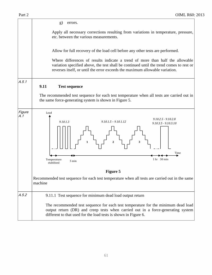
Part 2 OIML R60: 2013
61
g) errors.
Apply all necessary corrections resulting from variations in temperature, pressure, etc. between the various measurements.
Allow for full recovery of the load cell before any other tests are performed. Where differences of results indicate a trend of more than half the allowable variation specified above, the test shall be continued until the trend comes to rest or reverses itself, or until the error exceeds the maximum allowable variation.
A.5.1 9.11 Test sequence The recommended test sequence for each test temperature when all tests are carried out in the same force-generating system is shown in Figure 5.
Figure A.1
Figure 5 Recommended test sequence for each test temperature when all tests are carried out in the same machine
A.5.2 9.11.1 Test sequence for minimum dead load output return
The recommended test sequence for each test temperature for the minimum dead load output return (DR) and creep tests when carried out in a force-generating system different to that used for the load tests is shown in Figure 6.
9.10.2.5 - 9.10.2.8 9.10.3.5 - 9.10.3.10
1 2 3
1 hr Temperature stabilized
Load
Time
5 min 30 min
9.10.1.3 9.10.1.5 – 9.10.1.12
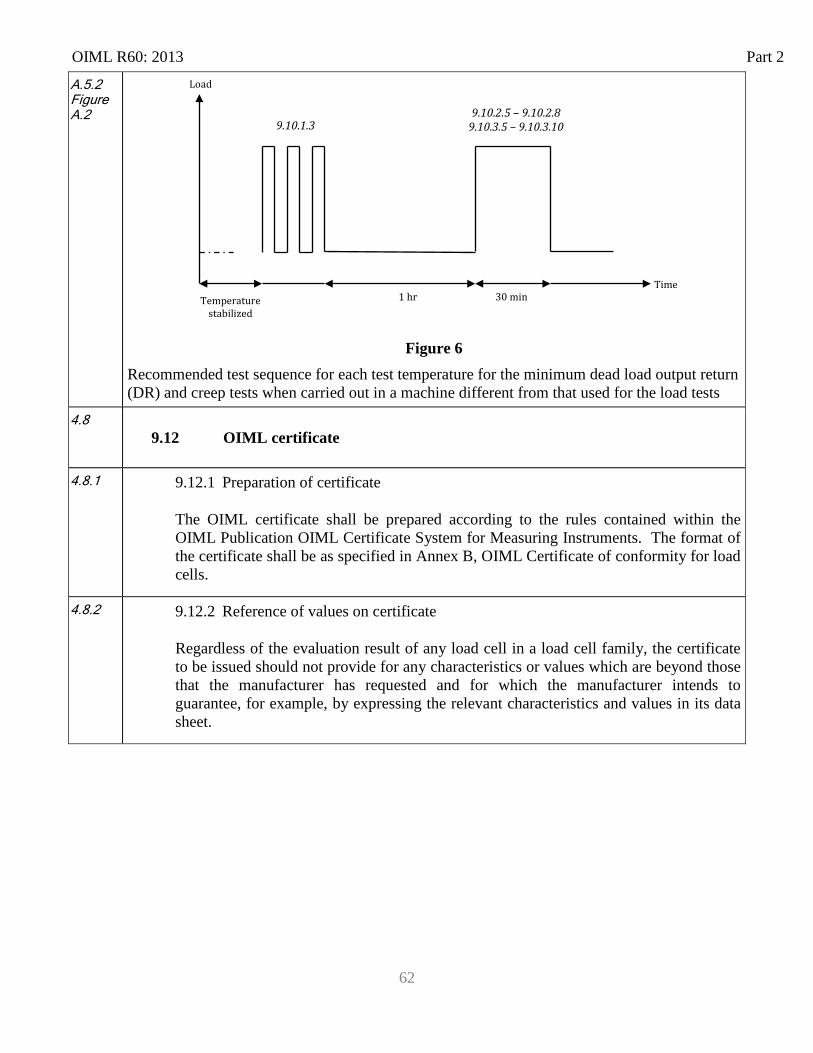
OIML R60: 2013 Part 2
62
A.5.2 Figure A.2
Figure 6 Recommended test sequence for each test temperature for the minimum dead load output return (DR) and creep tests when carried out in a machine different from that used for the load tests
4.8 9.12 OIML certificate
4.8.1 9.12.1 Preparation of certificate
The OIML certificate shall be prepared according to the rules contained within the OIML Publication OIML Certificate System for Measuring Instruments. The format of the certificate shall be as specified in Annex B, OIML Certificate of conformity for load cells.
4.8.2 9.12.2 Reference of values on certificate
Regardless of the evaluation result of any load cell in a load cell family, the certificate to be issued should not provide for any characteristics or values which are beyond those that the manufacturer has requested and for which the manufacturer intends to guarantee, for example, by expressing the relevant characteristics and values in its data sheet.
Load
1 hr Temperature stabilized
30 min Time
9.10.1.3 9.10.2.5 – 9.10.2.8
9.10.3.5 – 9.10.3.10
OIML R60-Parts 1&2: May 2013 Annex A
A-1
Annex A (Mandatory) Definitions from other applicable international publications
A.1 Definitions from VIM [3]
A.1.1 Measured quantity value [VIM 2.10)] Quantity value representing a measurement result (For notes, please refer to VIM)
A.1.2 Measurement error [VIM 2.16)] Measured quantity minus a reference quantity value. (For notes, please refer to VIM)
A.1.3 Measurement repeatability [VIM 2.21] Measurement precision under a set of repeatability conditions of measurement
A.1.4 Influence quantity [VIM 2.52] Quantity that, in a direct measurement, does not affect the quantity that is actually measured, but affects the relation between the indication and the measurement result. (For examples and notes, please refer to VIM)
A.1.5 measuring transducer [VIM 3.7] Device, used in measurement, that provides an output quantity having a specified relation to the input quantity.
A.1.6 rated operating condition [VIM 4.9] operating condition that must be fulfilled during measurement in order that a measuring instrument or measuring system perform as designed (For notes, please refer to VIM)
A.1.7 Reference operating condition [VIM 4.11] Operating condition prescribed for evaluating the performance of a measuring instrument or measuring system or for comparison of measurement results (For notes, please refer to VIM)
A.1.8 Sensitivity of a measuring system [VIM 4.12]
Annex A OIML R60-Parts 1&2: May 2013
A-2
Quotient of the change in an indication of a measuring system and the corresponding change in a value of a quantity being measured
A.1.9 Resolution [VIM 4.14] Smallest change in a quantity being measured that causes a perceptible change in the corresponding indication (For note, please refer to VIM)
A.1.10 Resolution of a displaying device [VIM 4.15] Smallest difference between displayed indications that can be meaningfully distinguished
A.1.11 Maximum permissible measurement error [VIM 4.26] Extreme value of measurement error, with respect to a known reference quantity value, permitted by specifications or regulations for a given measurement, measuring instrument, or measuring system. (For notes, please refer to VIM)
A.2 Definitions from the VIML [2]
A.2.1 legal metrology [VIML 1.01] Practice and process of applying statutory and regulatory structure and enforcement to metrology (For notes, please refer to VIML)
A.2.2 metrological supervision [VIML 2.03] Activity of legal metrological control to check the observance of metrology laws and regulations. (For notes, please refer to VIML)
A.2.3 type (pattern) evaluation [VIML 2.04] Conformity assessment procedure on one or more specimens of an identified type (pattern) of measuring instruments which results in an evaluation report and / or an evaluation certificate. (For notes, please refer to VIML)
A.2.4 type approval [VIML 2.05] Decision of legal relevance, based on the review of the type evaluation report, that the type of a measuring instrument complies with the relevant statutory requirements and results in the issuance of the type approval certificate
OIML R60-Parts 1&2: May 2013 Annex A
A-3
A.2.5 verification of a measuring instrument [VIML 2.09] Conformity assessment procedure (other than type evaluation) which results in the affixing of a verification mark and/or issuing of a verification certificate (For notes, please refer to VIML)
A.2.6 preliminary examination [VIML 2.10] Examination of a measuring instrument either to partial requirements or before certain elements of the measuring instrument are installed as part of the verification procedure
A.2.7 verification by sampling [VIML 2.11] verification of a homogeneous batch of measuring instruments based on the results of examination of a statistically appropriate number of specimens selected at random from an identified lot
A.2.8 inspection by sampling [VIML 2.18] inspection of a homogeneous batch of measuring instruments based on the results of evaluation of a statistically appropriate number of specimens selected at random from an identified lot
A.2.9 marking [VIML 2.19] Affixing of one or more marks (For notes, please refer to VIML)
A.2.10 sealing mark [VIML 2.20] Means intended to protect the measuring instrument against any unauthorized modification, readjustment, removal of parts, software, etc. (For notes, please refer to VIML)
A.3 Definitions from OIML D 11 [4] (For definitions in OIML D 11 that are copied from the VIM, see E.1)
A.3.1 Electronic measuring instrument (OIML D 11, 3.1) Measuring instrument intended to measure an electrical or non-electrical quantity using electronic means and/or equipped with electronic devices. (For notes, please refer to OIML D 11)
A.3.2 Electronic device (OIML D 11, 3.2)
Annex A OIML R60-Parts 1&2: May 2013
A-4
Device employing electronic sub-assemblies and performing a specific function. Electronic devices are usually manufactured as separate units and are capable of being tested independently (For notes, please refer to OIML D 11)
A.3.3 Electronic sub-assembly (OIML D 11, 3.3) Part of an electronic device, employing electronic components and having a recognizable function of its own. Examples: amplifiers, comparators, power converters. (For notes, please refer to OIML D 11)
A.3.4 Electronic component (OIML D11, 3.4) Smallest physical entity that uses electron or hole conduction in semi-conductors, gases or in a vacuum.
A.3.5 Examples: electronic tubes, transistors, integrated circuits.Initial intrinsic error (OIML D
11, 3.8) Intrinsic error of a measuring instrument as determined prior to performance tests and durability evaluations.
A.3.6 Fault (OIML D 11, 3.9) Difference between the error of indication and the intrinsic error of a measuring instrument. (For notes, please refer to OIML D 11)
A.3.7 Significant fault (OIML D 11, 3.10) Fault greater than the value specified in the relevant Recommendation (For notes, please refer to OIML D 11)
A.3.8 Durability error (OIML D 11, 3.11) Difference between the intrinsic error after a period of use and the initial intrinsic error of a measuring instrument.
A.3.9 Significant durability error (OIML D 11, 3.12) Durability error greater than the value specified in the relevant Recommendation. (For notes, please refer to OIML D 11)
A.3.10 Influence factor (OIML D 11, 3.13.1)
OIML R60-Parts 1&2: May 2013 Annex A
A-5
Influence quantity having a value within the rated operating conditions of a measuring instrument specified in the relevant Recommendation.
A.3.11 Disturbance (OIML D 11, 3.13.2) Influence quantity having a value within the limits specified in the relevant Recommendation, but outside the specified rated operating conditions of a measuring instrument. (For notes, please refer to OIML D 11)
A.3.12 Rated operating conditions [OIML D 11, 3.14] Conditions of use giving the range of values of influence quantities for which specified metrological characteristics of a measuring instrument are intended to lie within given limits.
A.3.13 Performance (OIML D 11, 3.16) Ability of a measuring instrument to accomplish its intended functions.
A.3.14 Durability (OIML D 11, 3.17) Ability of a measuring instrument to maintain its performance characteristics over a period of use.
A.3.15 Automatic checking facility (OIML D 11, 3.18.1) Checking facility that operates without the intervention of an operator.
A.3.16 Permanent automatic checking facility (type P) (OIML D 11, 3.18.1.1) Automatic checking facility that operates at each measurement cycle.
A.3.17 Intermittent automatic checking facility (type I) (OIML D 11, 3.18.1.2) Automatic checking facility that operates at certain time intervals or per fixed number of measurement cycles.
A.3.18 Non-automatic checking facility (type N) (OIML D 11, 3.18.2) Checking facility that requires the intervention of an operator.
A.3.19 Durability protection facility (OIML D 11, 3.19) Facility that is incorporated in a measuring instrument and which enables significant durability errors to be detected and acted upon.
Annex A OIML R60-Parts 1&2: May 2013
A-6
A.3.20 Test (OIML D 11, 3.20) Series of operations intended to verify the compliance of the equipment under test (EUT) with specified requirements.
A.3.21 Test procedure (OIML D 11, 3.20.1) Detailed description of the test operations.
A.3.22 Test program (OIML D 11, 3.20.2) Description of a series of tests for certain types of equipment.
A.3.23 Performance test (OIML D 11, 3.20.3) Test intended to verify whether the EUT is able to accomplish its intended functions
A.3.24 Durability test (OIML D 11, 3.20.4) Test intended to verify whether the EUT is able to maintain its performance characteristics over a period of use.
A.3.25 Mains power (OIML D 11, 3.21) Primary external source of electrical power for an instrument, including all sub-assemblies. (Examples: public power (AC or DC), generator, external battery or other DC supply systems)
A.3.26 Power converter (power supply device) (OIML D 11, 3.22) Sub-assembly converting the voltage from the mains power to a voltage suitable for other sub-assemblies.
A.3.27 Auxiliary battery (OIML D 11, 3.23) Battery that is: Mounted in, or connected to, an instrument that can be powered by the mains power as well;
and Capable of completely powering the instrument for a reasonable period of time.
A.3.28 Back-up battery (OIML D 11, 3.24) Battery that is intended to power specific functions of an instrument in the absence of the primary power supply. Example: to preserve stored data.
OIML R60-Parts 1&2: May 2013 Annex A
A-7
A.4 Definitions from OIML B 3 [5]
A.4.1 Category of instruments [B 3, 2.2] Identification or classification of instruments according to unique metrological and technical characteristics that may include the measured quantity, the measuring range, and the principle or method of measurement.
A.4.2 Family of measuring instruments [B 3, 2.3] Identifiable group of measuring instruments belonging to the same manufactured type within the same category that have the same design features and metrological principles for measurement but which may differ in some metrological and technical performance characteristics, as defined in the relevant Recommendation.
A.4.3 Module [B 3, 2.4] Identifiable part of a measuring instrument or of a family of measuring instruments that performs a specific function or functions and that can be separately evaluated according to prescribed metrological and technical performance requirements in the relevant Recommendation.
A.4.4 Family of modules [B 3, 2.5] Identifiable group of modules belonging to the same manufactured type that have similar design features but may differ in some metrological and technical performance requirements as defined in the relevant Recommendation
A.5 Definitions from OIML R76 [2]
A.5.1 Weighing Module [T.2.2.7] Part of the weighing instrument that comprises all mechanical and electronic devices (i.e. load receptor, load-transmitting device, load cell, and analog data processing device or digital data processing device) but not having the means to display the weighing result. It may optionally have devices for further processing (digital) data and operating the instrument.
A.5.2 Influence quantity [T.6.1] Quantity that is not the subject of the measurement but which influences the values of the measurand or the indication of the instrument.

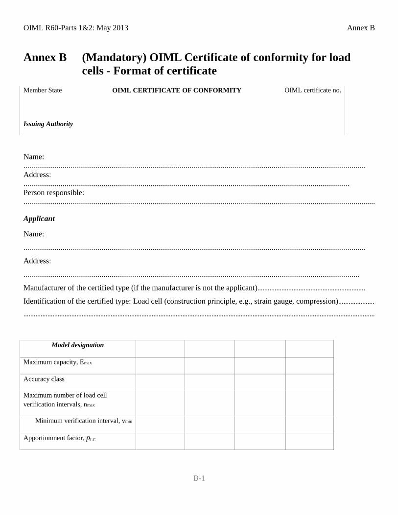
OIML R60-Parts 1&2: May 2013 Annex B
B-1
Annex B (Mandatory) OIML Certificate of conformity for load cells - Format of certificate
Member State OIML CERTIFICATE OF CONFORMITY OIML certificate no.
Issuing Authority
Name: ............................................................................................................................................................................... Address: ....................................................................................................................................................................... Person responsible: ....................................................................................................................................................................................
Applicant
Name:
...............................................................................................................................................................................
Address:
............................................................................................................................................................................
Manufacturer of the certified type (if the manufacturer is not the applicant)...............................................................
Identification of the certified type: Load cell (construction principle, e.g., strain gauge, compression).....................
...................................................................................................................................................................... .......................................
Model designation
Maximum capacity, Emax
Accuracy class
Maximum number of load cell verification intervals, nmax
Minimum verification interval, vmin
Apportionment factor, pLC
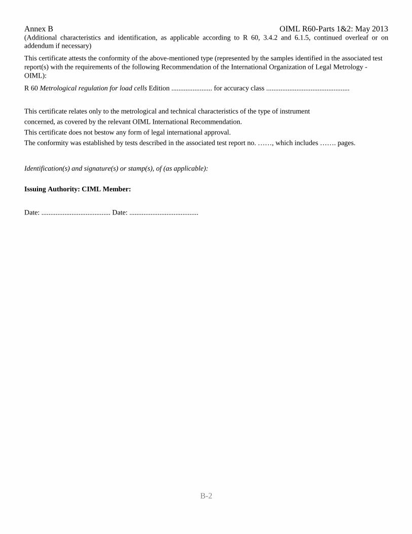
Annex B OIML R60-Parts 1&2: May 2013
B-2
(Additional characteristics and identification, as applicable according to R 60, 3.4.2 and 6.1.5, continued overleaf or on addendum if necessary)
This certificate attests the conformity of the above-mentioned type (represented by the samples identified in the associated test report(s) with the requirements of the following Recommendation of the International Organization of Legal Metrology - OIML):
R 60 Metrological regulation for load cells Edition ....................... for accuracy class ...............................................
This certificate relates only to the metrological and technical characteristics of the type of instrument concerned, as covered by the relevant OIML International Recommendation. This certificate does not bestow any form of legal international approval. The conformity was established by tests described in the associated test report no. ……, which includes ……. pages.
Identification(s) and signature(s) or stamp(s), of (as applicable):
Issuing Authority: CIML Member:
Date: ....................................... Date: .......................................
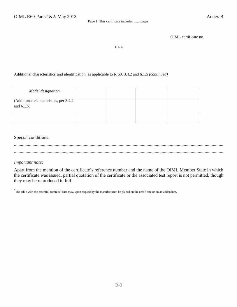
OIML R60-Parts 1&2: May 2013 Annex B
B-3
Page 1. This certificate includes ....... pages.
OIML certificate no.
* * *
Additional characteristics1 and identification, as applicable to R 60, 3.4.2 and 6.1.5 (continued)
Model designation
(Additional characteristics, per 3.4.2 and 6.1.5)
Special conditions: ........................................................................................................................................................................................................................................................................................................................................................................
Important note: Apart from the mention of the certificate’s reference number and the name of the OIML Member State in which the certificate was issued, partial quotation of the certificate or the associated test report is not permitted, though they may be reproduced in full.
1 The table with the essential technical data may, upon request by the manufacturer, be placed on the certificate or on an addendum.
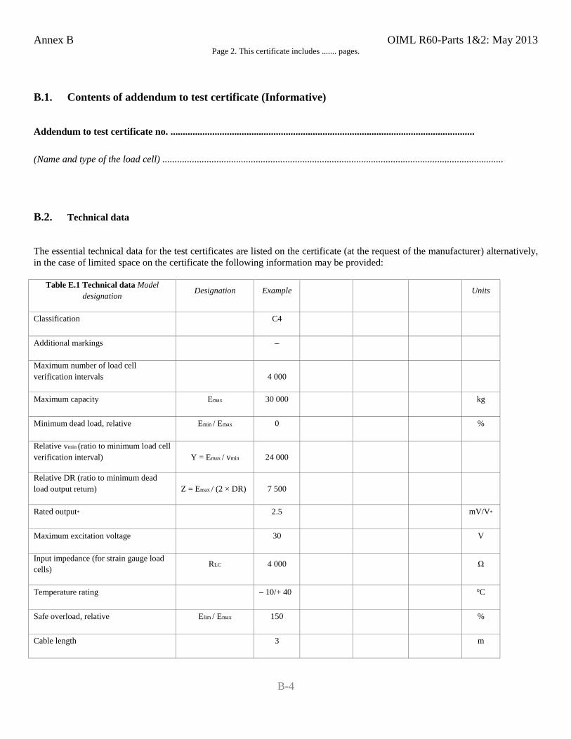
Annex B OIML R60-Parts 1&2: May 2013
B-4
Page 2. This certificate includes ....... pages.
B.1. Contents of addendum to test certificate (Informative)
Addendum to test certificate no. ............................................................................................................................
(Name and type of the load cell) ...........................................................................................................................................
B.2. Technical data
The essential technical data for the test certificates are listed on the certificate (at the request of the manufacturer) alternatively, in the case of limited space on the certificate the following information may be provided:
Table E.1 Technical data Model designation Designation Example Units
Classification C4
Additional markings –
Maximum number of load cell verification intervals
4 000
Maximum capacity Emax 30 000 kg
Minimum dead load, relative Emin / Emax 0 %
Relative vmin (ratio to minimum load cell verification interval) Y = Emax / vmin 24 000
Relative DR (ratio to minimum dead load output return) Z = Emax / (2 × DR) 7 500
Rated output* 2.5 mV/V*
Maximum excitation voltage 30 V
Input impedance (for strain gauge load cells) RLC 4 000 Ω
Temperature rating – 10/+ 40 °C
Safe overload, relative Elim / Emax 150 %
Cable length 3 m
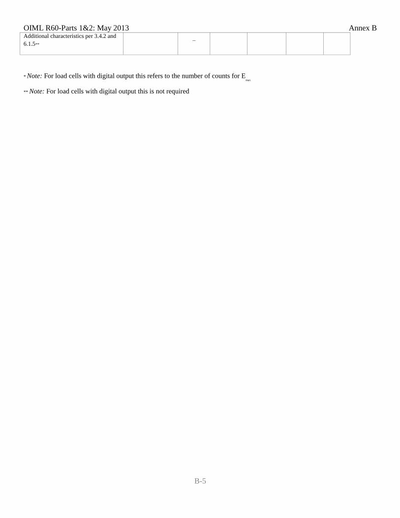
OIML R60-Parts 1&2: May 2013 Annex B
B-5
Additional characteristics per 3.4.2 and 6.1.5**
–
* Note: For load cells with digital output this refers to the number of counts for Emax
** Note: For load cells with digital output this is not required
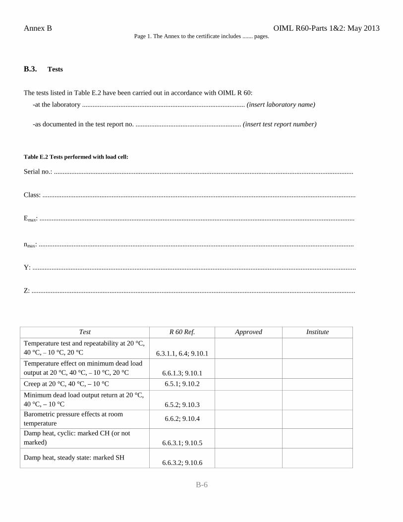
Annex B OIML R60-Parts 1&2: May 2013
B-6
Page 1. The Annex to the certificate includes ....... pages.
B.3. Tests
The tests listed in Table E.2 have been carried out in accordance with OIML R 60:
-at the laboratory .............................................................................................. (insert laboratory name)
-as documented in the test report no. ............................................................. (insert test report number)
Table E.2 Tests performed with load cell:
Serial no.: .............................................................................................................................................................................
Class: .....................................................................................................................................................................................
Emax: ......................................................................................................................................................................................
nmax: ......................................................................................................................................................................................
Y: ...........................................................................................................................................................................................
Z: ...........................................................................................................................................................................................
Test R 60 Ref. Approved Institute Temperature test and repeatability at 20 °C, 40 °C, – 10 °C, 20 °C 6.3.1.1, 6.4; 9.10.1
Temperature effect on minimum dead load output at 20 °C, 40 °C, – 10 °C, 20 °C 6.6.1.3; 9.10.1
Creep at 20 °C, 40 °C, – 10 °C 6.5.1; 9.10.2 Minimum dead load output return at 20 °C, 40 °C, – 10 °C 6.5.2; 9.10.3
Barometric pressure effects at room temperature 6.6.2; 9.10.4
Damp heat, cyclic: marked CH (or not marked) 6.6.3.1; 9.10.5
Damp heat, steady state: marked SH 6.6.3.2; 9.10.6
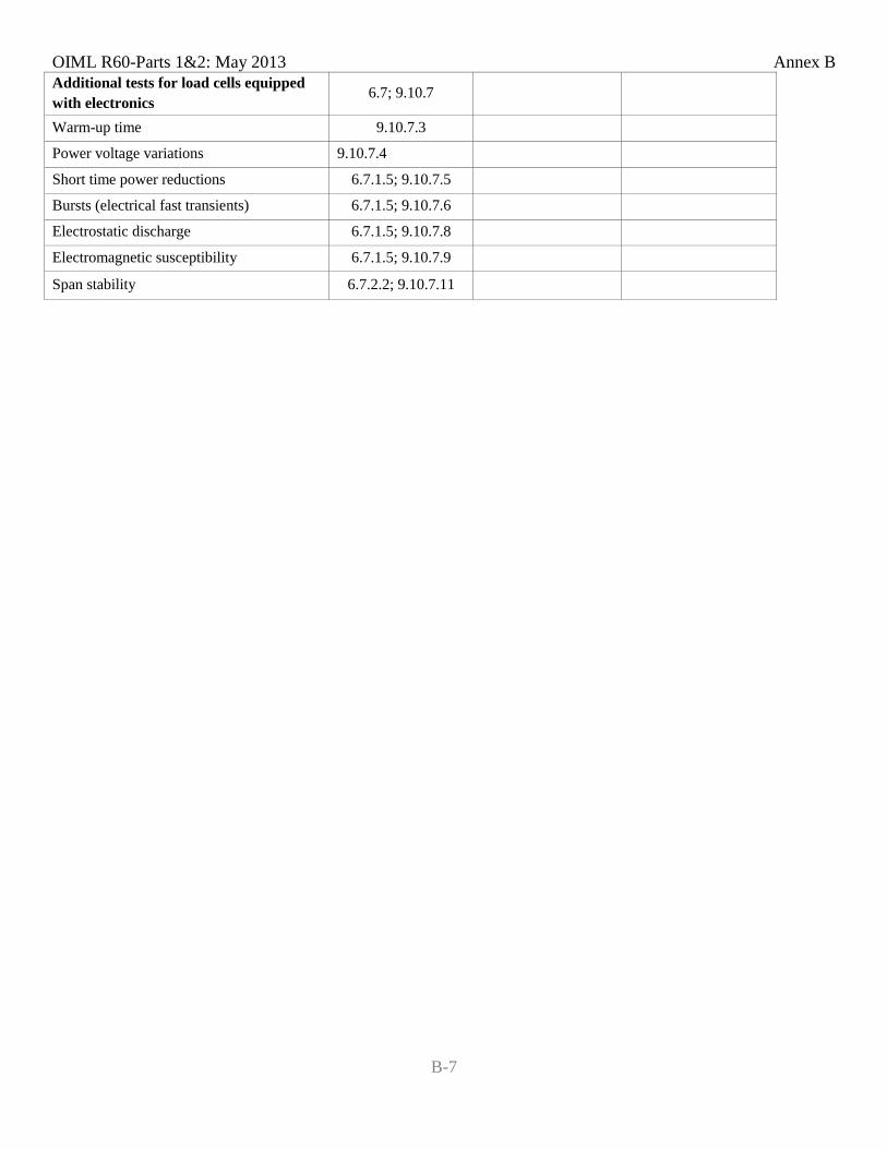
OIML R60-Parts 1&2: May 2013 Annex B
B-7
Additional tests for load cells equipped with electronics
6.7; 9.10.7
Warm-up time 9.10.7.3 Power voltage variations 9.10.7.4 Short time power reductions 6.7.1.5; 9.10.7.5 Bursts (electrical fast transients) 6.7.1.5; 9.10.7.6 Electrostatic discharge 6.7.1.5; 9.10.7.8 Electromagnetic susceptibility 6.7.1.5; 9.10.7.9 Span stability 6.7.2.2; 9.10.7.11

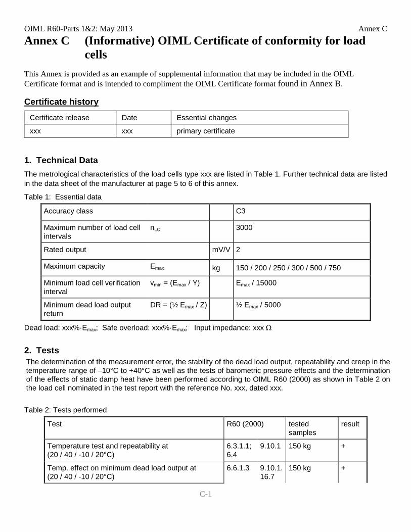
OIML R60-Parts 1&2: May 2013 Annex C
C-1
Annex C (Informative) OIML Certificate of conformity for load cells
This Annex is provided as an example of supplemental information that may be included in the OIML Certificate format and is intended to compliment the OIML Certificate format found in Annex B.
Certificate history Certificate release Date Essential changes
xxx xxx primary certificate
1. Technical Data The metrological characteristics of the load cells type xxx are listed in Table 1. Further technical data are listed in the data sheet of the manufacturer at page 5 to 6 of this annex.
Table 1: Essential data
Accuracy class C3
Maximum number of load cell intervals
nLC 3000
Rated output mV/V 2
Maximum capacity Emax kg 150 / 200 / 250 / 300 / 500 / 750
Minimum load cell verification interval
vmin = (Emax / Y) Emax / 15000
Minimum dead load output return
DR = (½ Emax / Z) ½ Emax / 5000
Dead load: xxx%·Emax; Safe overload: xxx%·Emax; Input impedance: xxx Ω
2. Tests The determination of the measurement error, the stability of the dead load output, repeatability and creep in the temperature range of –10°C to +40°C as well as the tests of barometric pressure effects and the determination of the effects of static damp heat have been performed according to OIML R60 (2000) as shown in Table 2 on the load cell nominated in the test report with the reference No. xxx, dated xxx. Table 2: Tests performed
Test R60 (2000) tested samples
result
Temperature test and repeatability at (20 / 40 / -10 / 20°C)
6.3.1.1; 6.4
9.10.1 150 kg +
Temp. effect on minimum dead load output at (20 / 40 / -10 / 20°C)
6.6.1.3 9.10.1.16.7
150 kg +
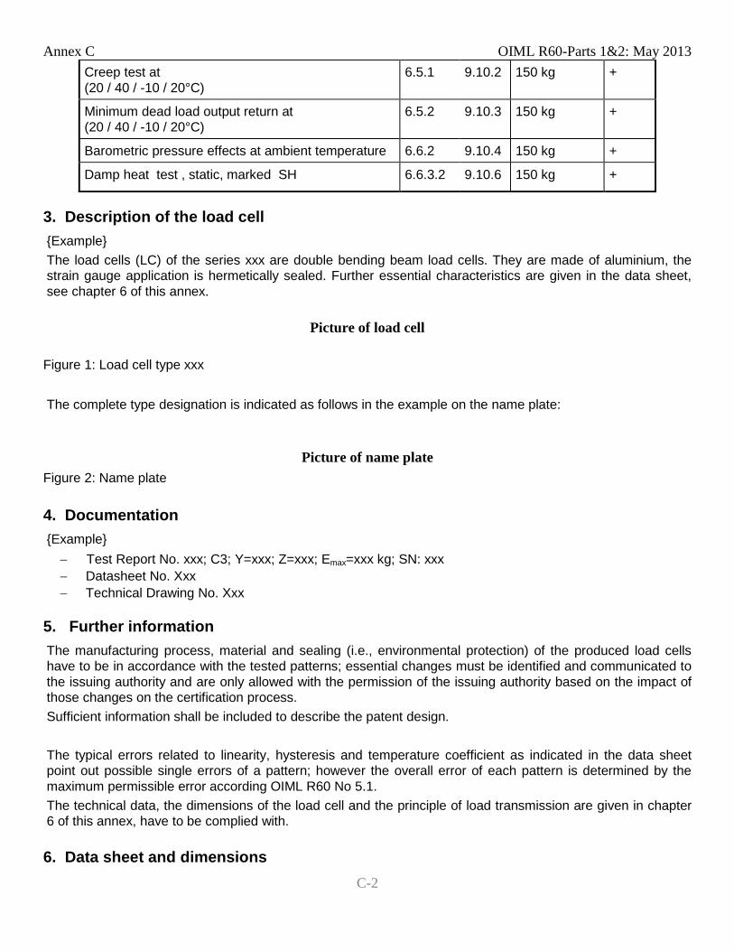
Annex C OIML R60-Parts 1&2: May 2013
C-2
Creep test at (20 / 40 / -10 / 20°C)
6.5.1 9.10.2 150 kg +
Minimum dead load output return at (20 / 40 / -10 / 20°C)
6.5.2 9.10.3 150 kg +
Barometric pressure effects at ambient temperature 6.6.2 9.10.4 150 kg +
Damp heat test , static, marked SH 6.6.3.2 9.10.6 150 kg +
3. Description of the load cell Example The load cells (LC) of the series xxx are double bending beam load cells. They are made of aluminium, the strain gauge application is hermetically sealed. Further essential characteristics are given in the data sheet, see chapter 6 of this annex.
Picture of load cell
Figure 1: Load cell type xxx
The complete type designation is indicated as follows in the example on the name plate:
Picture of name plate Figure 2: Name plate
4. Documentation Example − Test Report No. xxx; C3; Y=xxx; Z=xxx; Emax=xxx kg; SN: xxx − Datasheet No. Xxx − Technical Drawing No. Xxx
5. Further information The manufacturing process, material and sealing (i.e., environmental protection) of the produced load cells have to be in accordance with the tested patterns; essential changes must be identified and communicated to the issuing authority and are only allowed with the permission of the issuing authority based on the impact of those changes on the certification process. Sufficient information shall be included to describe the patent design. The typical errors related to linearity, hysteresis and temperature coefficient as indicated in the data sheet point out possible single errors of a pattern; however the overall error of each pattern is determined by the maximum permissible error according OIML R60 No 5.1. The technical data, the dimensions of the load cell and the principle of load transmission are given in chapter 6 of this annex, have to be complied with. 6. Data sheet and dimensions
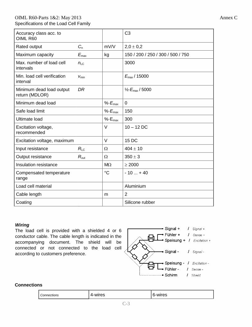
OIML R60-Parts 1&2: May 2013 Annex C
C-3
Specifications of the Load Cell Family
Accuracy class acc. to OIML R60
C3
Rated output Cn mV/V 2,0 ± 0,2
Maximum capacity Emax kg 150 / 200 / 250 / 300 / 500 / 750
Max. number of load cell intervals
nLC 3000
Min. load cell verification interval
vmin Emax / 15000
Minimum dead load output return (MDLOR)
DR ½·Emax / 5000
Minimum dead load %·Emax 0
Safe load limit %·Emax 150
Ultimate load %·Emax 300
Excitation voltage, recommended
V 10 – 12 DC
Excitation voltage, maximum V 15 DC
Input resistance RLC Ω 404 ± 10
Output resistance Rout Ω 350 ± 3
Insulation resistance MΩ ≥ 2000
Compensated temperature range
°C - 10 ... + 40
Load cell material Aluminium
Cable length m 2
Coating Silicone rubber
Wiring The load cell is provided with a shielded 4 or 6 conductor cable. The cable length is indicated in the accompanying document. The shield will be connected or not connected to the load cell according to customers preference.
Connections
Connections 4-wires 6-wires
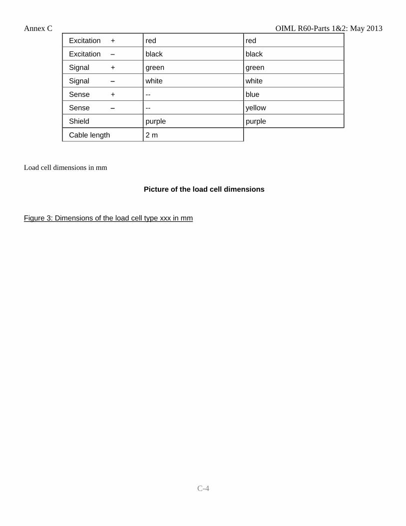
Annex C OIML R60-Parts 1&2: May 2013
C-4
Excitation + red red
Excitation − black black
Signal + green green
Signal − white white
Sense + -- blue
Sense − -- yellow
Shield purple purple
Cable length 2 m
Load cell dimensions in mm
Picture of the load cell dimensions
Figure 3: Dimensions of the load cell type xxx in mm
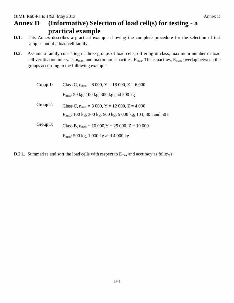
OIML R60-Parts 1&2: May 2013 Annex D
D-1
Annex D (Informative) Selection of load cell(s) for testing - a practical example
D.1. This Annex describes a practical example showing the complete procedure for the selection of test samples out of a load cell family.
D.2. Assume a family consisting of three groups of load cells, differing in class, maximum number of load cell verification intervals, nmax, and maximum capacities, Emax. The capacities, Emax, overlap between the groups according to the following example:
Group 1: Class C, nmax = 6 000, Y = 18 000, Z = 6 000
Emax: 50 kg, 100 kg, 300 kg and 500 kg
Group 2: Class C, nmax = 3 000, Y = 12 000, Z = 4 000
Emax: 100 kg, 300 kg, 500 kg, 5 000 kg, 10 t, 30 t and 50 t
Group 3: Class B, nmax = 10 000,Y = 25 000, Z = 10 000
Emax: 500 kg, 1 000 kg and 4 000 kg
D.2.1. Summarize and sort the load cells with respect to Emax and accuracy as follows:
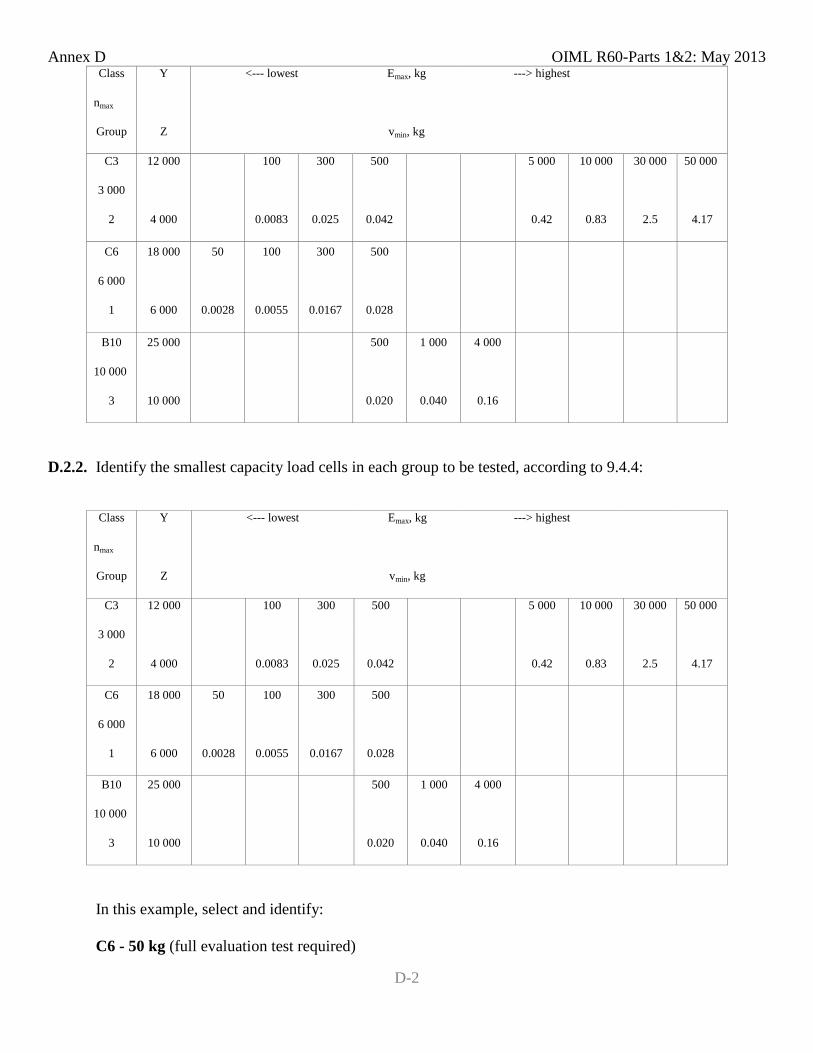
Annex D OIML R60-Parts 1&2: May 2013
D-2
Class Y <--- lowest Emax, kg ---> highest
nmax
Group Z vmin, kg
C3 12 000 100 300 500 5 000 10 000 30 000 50 000
3 000
2 4 000 0.0083 0.025 0.042 0.42 0.83 2.5 4.17
C6 18 000 50 100 300 500
6 000
1 6 000 0.0028 0.0055 0.0167 0.028
B10 25 000 500 1 000 4 000
10 000
3 10 000 0.020 0.040 0.16
D.2.2. Identify the smallest capacity load cells in each group to be tested, according to 9.4.4:
Class Y <--- lowest Emax, kg ---> highest
nmax
Group Z vmin, kg
C3 12 000 100 300 500 5 000 10 000 30 000 50 000
3 000
2 4 000 0.0083 0.025 0.042 0.42 0.83 2.5 4.17
C6 18 000 50 100 300 500
6 000
1 6 000 0.0028 0.0055 0.0167 0.028
B10 25 000 500 1 000 4 000
10 000
3 10 000 0.020 0.040 0.16
In this example, select and identify:
C6 - 50 kg (full evaluation test required)
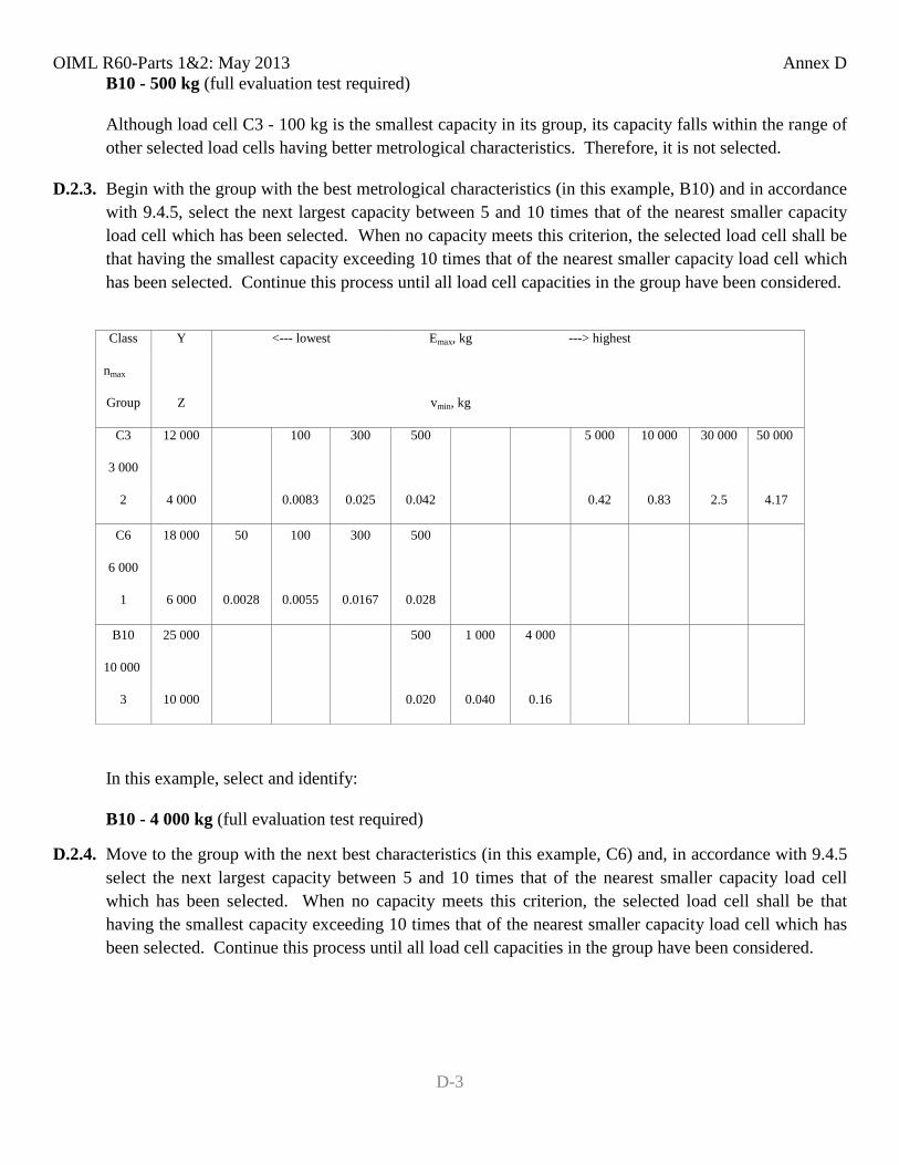
OIML R60-Parts 1&2: May 2013 Annex D
D-3
B10 - 500 kg (full evaluation test required)
Although load cell C3 - 100 kg is the smallest capacity in its group, its capacity falls within the range of other selected load cells having better metrological characteristics. Therefore, it is not selected.
D.2.3. Begin with the group with the best metrological characteristics (in this example, B10) and in accordance with 9.4.5, select the next largest capacity between 5 and 10 times that of the nearest smaller capacity load cell which has been selected. When no capacity meets this criterion, the selected load cell shall be that having the smallest capacity exceeding 10 times that of the nearest smaller capacity load cell which has been selected. Continue this process until all load cell capacities in the group have been considered.
Class Y <--- lowest Emax, kg ---> highest
nmax
Group Z vmin, kg
C3 12 000 100 300 500 5 000 10 000 30 000 50 000
3 000
2 4 000 0.0083 0.025 0.042 0.42 0.83 2.5 4.17
C6 18 000 50 100 300 500
6 000
1 6 000 0.0028 0.0055 0.0167 0.028
B10 25 000 500 1 000 4 000
10 000
3 10 000 0.020 0.040 0.16
In this example, select and identify:
B10 - 4 000 kg (full evaluation test required)
D.2.4. Move to the group with the next best characteristics (in this example, C6) and, in accordance with 9.4.5 select the next largest capacity between 5 and 10 times that of the nearest smaller capacity load cell which has been selected. When no capacity meets this criterion, the selected load cell shall be that having the smallest capacity exceeding 10 times that of the nearest smaller capacity load cell which has been selected. Continue this process until all load cell capacities in the group have been considered.
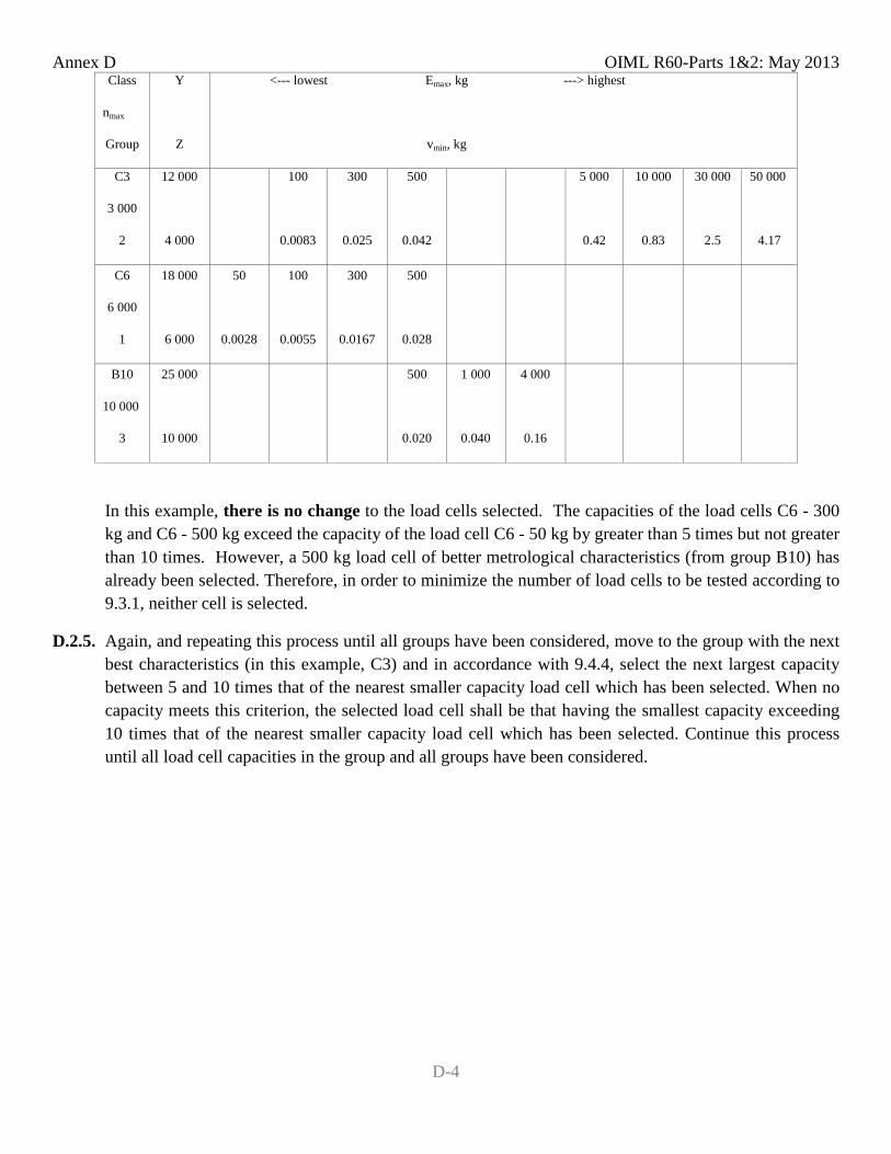
Annex D OIML R60-Parts 1&2: May 2013
D-4
Class Y <--- lowest Emax, kg ---> highest
nmax
Group Z vmin, kg
C3 12 000 100 300 500 5 000 10 000 30 000 50 000
3 000
2 4 000 0.0083 0.025 0.042 0.42 0.83 2.5 4.17
C6 18 000 50 100 300 500
6 000
1 6 000 0.0028 0.0055 0.0167 0.028
B10 25 000 500 1 000 4 000
10 000
3 10 000 0.020 0.040 0.16
In this example, there is no change to the load cells selected. The capacities of the load cells C6 - 300 kg and C6 - 500 kg exceed the capacity of the load cell C6 - 50 kg by greater than 5 times but not greater than 10 times. However, a 500 kg load cell of better metrological characteristics (from group B10) has already been selected. Therefore, in order to minimize the number of load cells to be tested according to 9.3.1, neither cell is selected.
D.2.5. Again, and repeating this process until all groups have been considered, move to the group with the next best characteristics (in this example, C3) and in accordance with 9.4.4, select the next largest capacity between 5 and 10 times that of the nearest smaller capacity load cell which has been selected. When no capacity meets this criterion, the selected load cell shall be that having the smallest capacity exceeding 10 times that of the nearest smaller capacity load cell which has been selected. Continue this process until all load cell capacities in the group and all groups have been considered.
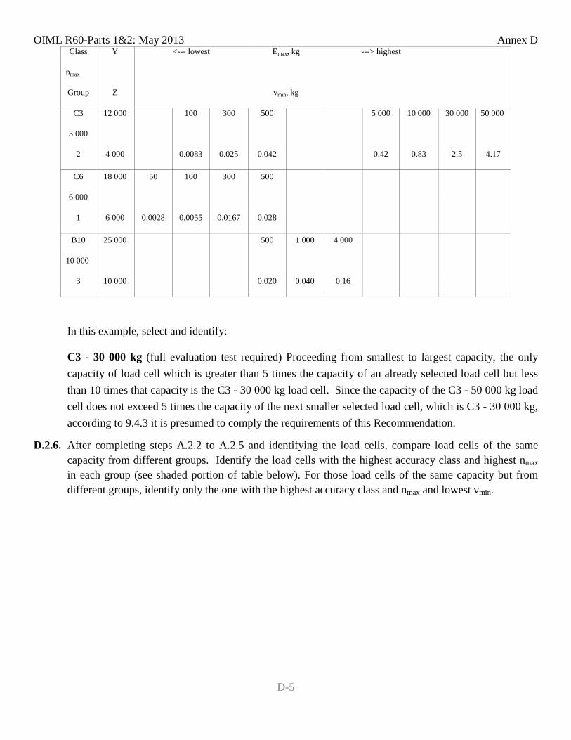
OIML R60-Parts 1&2: May 2013 Annex D
D-5
Class Y <--- lowest Emax, kg ---> highest
nmax
Group Z vmin, kg
C3 12 000 100 300 500 5 000 10 000 30 000 50 000
3 000
2 4 000 0.0083 0.025 0.042 0.42 0.83 2.5 4.17
C6 18 000 50 100 300 500
6 000
1 6 000 0.0028 0.0055 0.0167 0.028
B10 25 000 500 1 000 4 000
10 000
3 10 000 0.020 0.040 0.16
In this example, select and identify:
C3 - 30 000 kg (full evaluation test required) Proceeding from smallest to largest capacity, the only capacity of load cell which is greater than 5 times the capacity of an already selected load cell but less than 10 times that capacity is the C3 - 30 000 kg load cell. Since the capacity of the C3 - 50 000 kg load cell does not exceed 5 times the capacity of the next smaller selected load cell, which is C3 - 30 000 kg, according to 9.4.3 it is presumed to comply the requirements of this Recommendation.
D.2.6. After completing steps A.2.2 to A.2.5 and identifying the load cells, compare load cells of the same capacity from different groups. Identify the load cells with the highest accuracy class and highest nmax in each group (see shaded portion of table below). For those load cells of the same capacity but from different groups, identify only the one with the highest accuracy class and nmax and lowest vmin.
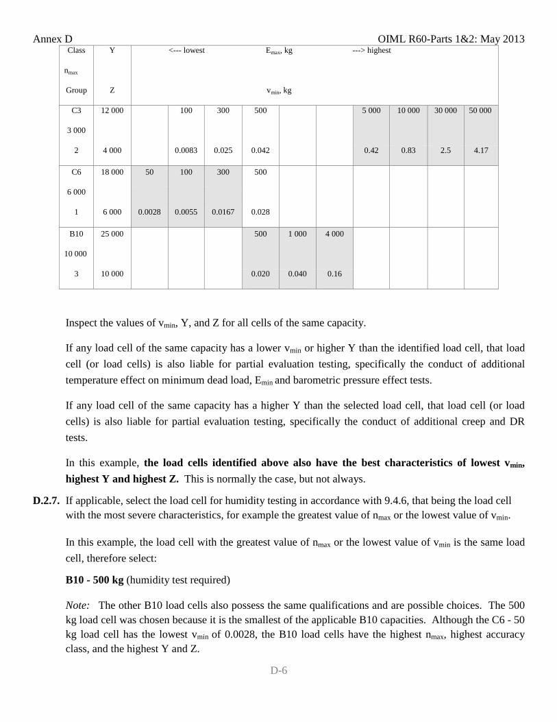
Annex D OIML R60-Parts 1&2: May 2013
D-6
Class Y <--- lowest Emax, kg ---> highest
nmax
Group Z vmin, kg
C3 12 000 100 300 500 5 000 10 000 30 000 50 000
3 000
2 4 000 0.0083 0.025 0.042 0.42 0.83 2.5 4.17
C6 18 000 50 100 300 500
6 000
1 6 000 0.0028 0.0055 0.0167 0.028
B10 25 000 500 1 000 4 000
10 000
3 10 000 0.020 0.040 0.16
Inspect the values of vmin, Y, and Z for all cells of the same capacity.
If any load cell of the same capacity has a lower vmin or higher Y than the identified load cell, that load cell (or load cells) is also liable for partial evaluation testing, specifically the conduct of additional temperature effect on minimum dead load, Emin and barometric pressure effect tests.
If any load cell of the same capacity has a higher Y than the selected load cell, that load cell (or load cells) is also liable for partial evaluation testing, specifically the conduct of additional creep and DR tests.
In this example, the load cells identified above also have the best characteristics of lowest vmin, highest Y and highest Z. This is normally the case, but not always.
D.2.7. If applicable, select the load cell for humidity testing in accordance with 9.4.6, that being the load cell with the most severe characteristics, for example the greatest value of nmax or the lowest value of vmin.
In this example, the load cell with the greatest value of nmax or the lowest value of vmin is the same load cell, therefore select:
B10 - 500 kg (humidity test required)
Note: The other B10 load cells also possess the same qualifications and are possible choices. The 500 kg load cell was chosen because it is the smallest of the applicable B10 capacities. Although the C6 - 50 kg load cell has the lowest vmin of 0.0028, the B10 load cells have the highest nmax, highest accuracy class, and the highest Y and Z.
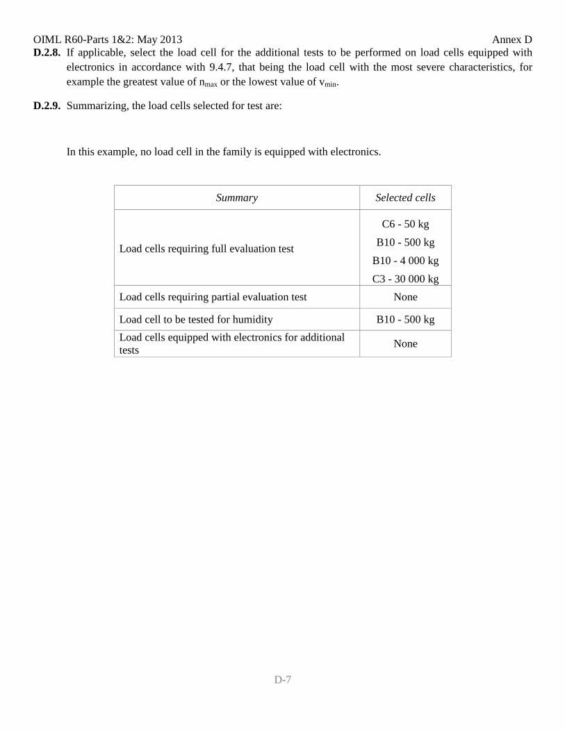
OIML R60-Parts 1&2: May 2013 Annex D
D-7
D.2.8. If applicable, select the load cell for the additional tests to be performed on load cells equipped with electronics in accordance with 9.4.7, that being the load cell with the most severe characteristics, for example the greatest value of nmax or the lowest value of vmin.
D.2.9. Summarizing, the load cells selected for test are:
In this example, no load cell in the family is equipped with electronics.
Summary Selected cells
C6 - 50 kg
Load cells requiring full evaluation test B10 - 500 kg B10 - 4 000 kg
C3 - 30 000 kg Load cells requiring partial evaluation test None
Load cell to be tested for humidity B10 - 500 kg Load cells equipped with electronics for additional tests None

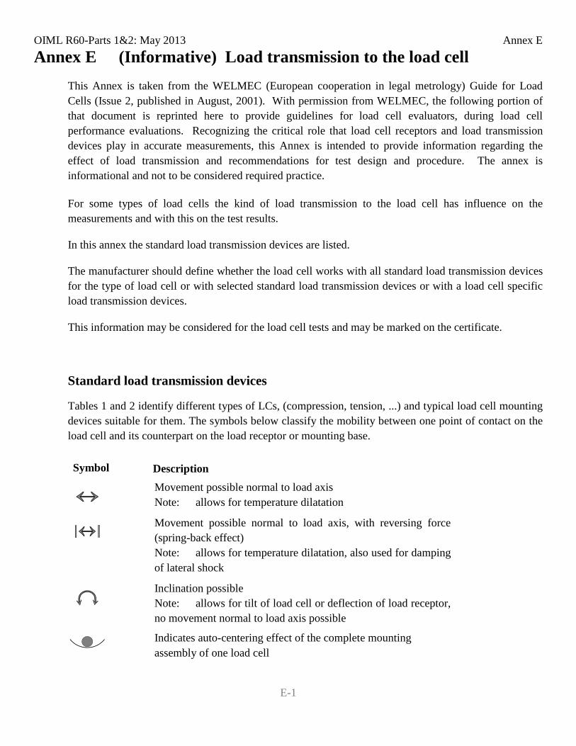
OIML R60-Parts 1&2: May 2013 Annex E
E-1
Annex E (Informative) Load transmission to the load cell This Annex is taken from the WELMEC (European cooperation in legal metrology) Guide for Load Cells (Issue 2, published in August, 2001). With permission from WELMEC, the following portion of that document is reprinted here to provide guidelines for load cell evaluators, during load cell performance evaluations. Recognizing the critical role that load cell receptors and load transmission devices play in accurate measurements, this Annex is intended to provide information regarding the effect of load transmission and recommendations for test design and procedure. The annex is informational and not to be considered required practice.
For some types of load cells the kind of load transmission to the load cell has influence on the measurements and with this on the test results.
In this annex the standard load transmission devices are listed.
The manufacturer should define whether the load cell works with all standard load transmission devices for the type of load cell or with selected standard load transmission devices or with a load cell specific load transmission devices.
This information may be considered for the load cell tests and may be marked on the certificate.
Standard load transmission devices
Tables 1 and 2 identify different types of LCs, (compression, tension, ...) and typical load cell mounting devices suitable for them. The symbols below classify the mobility between one point of contact on the load cell and its counterpart on the load receptor or mounting base. Symbol Description
Movement possible normal to load axis Note: allows for temperature dilatation
Movement possible normal to load axis, with reversing force (spring-back effect) Note: allows for temperature dilatation, also used for damping of lateral shock
Inclination possible Note: allows for tilt of load cell or deflection of load receptor, no movement normal to load axis possible
Indicates auto-centering effect of the complete mounting assembly of one load cell
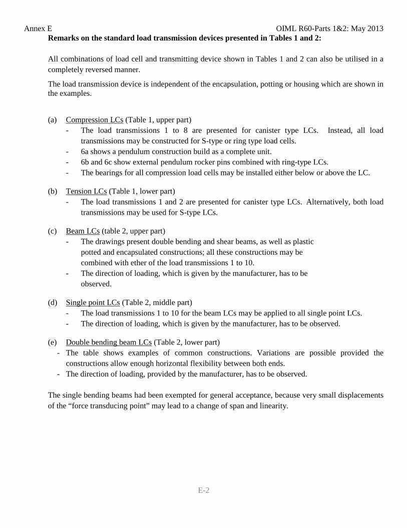
Annex E OIML R60-Parts 1&2: May 2013
E-2
Remarks on the standard load transmission devices presented in Tables 1 and 2: All combinations of load cell and transmitting device shown in Tables 1 and 2 can also be utilised in a completely reversed manner.
The load transmission device is independent of the encapsulation, potting or housing which are shown in the examples.
(a) Compression LCs (Table 1, upper part) - The load transmissions 1 to 8 are presented for canister type LCs. Instead, all load
transmissions may be constructed for S-type or ring type load cells. - 6a shows a pendulum construction build as a complete unit. - 6b and 6c show external pendulum rocker pins combined with ring-type LCs. - The bearings for all compression load cells may be installed either below or above the LC.
(b) Tension LCs (Table 1, lower part) - The load transmissions 1 and 2 are presented for canister type LCs. Alternatively, both load
transmissions may be used for S-type LCs.
(c) Beam LCs (table 2, upper part) - The drawings present double bending and shear beams, as well as plastic
potted and encapsulated constructions; all these constructions may be combined with ether of the load transmissions 1 to 10. - The direction of loading, which is given by the manufacturer, has to be observed.
(d) Single point LCs (Table 2, middle part) - The load transmissions 1 to 10 for the beam LCs may be applied to all single point LCs.
- The direction of loading, which is given by the manufacturer, has to be observed.
(e) Double bending beam LCs (Table 2, lower part) - The table shows examples of common constructions. Variations are possible provided the
constructions allow enough horizontal flexibility between both ends. - The direction of loading, provided by the manufacturer, has to be observed. The single bending beams had been exempted for general acceptance, because very small displacements of the “force transducing point” may lead to a change of span and linearity.
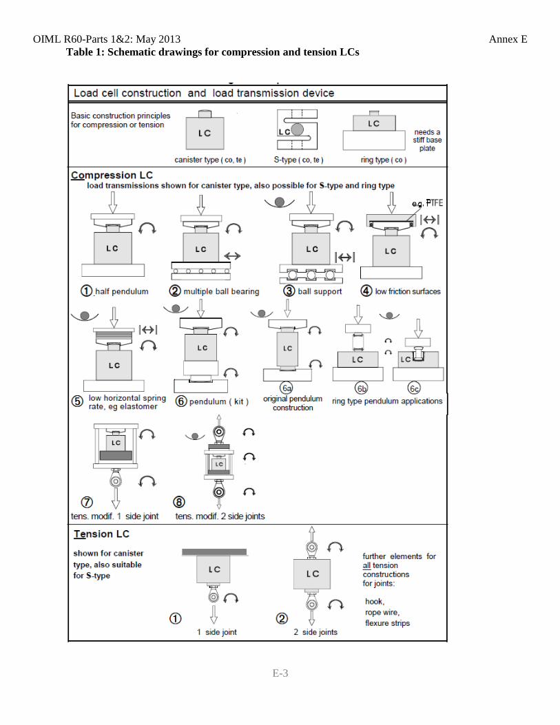
OIML R60-Parts 1&2: May 2013 Annex E
E-3
Table 1: Schematic drawings for compression and tension LCs
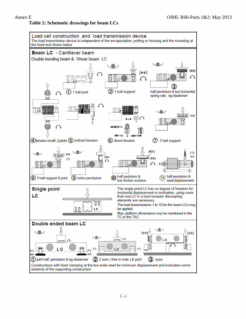
Annex E OIML R60-Parts 1&2: May 2013
E-4
Table 2: Schematic drawings for beam LCs
OIML R60-Parts 1&2: May 2013 Bibliography
i
Bibliography [1] "OIML D11 General requirements for electronic measuring instruments.," 2004. [2] "OIML R76 Non-automatic weighing instruments," 2006. [3] "ISO/IEC Guide 99 OIML V 2-200 International Vocabulary of Metrology - Basic and General Concepts
and Associated Terms," 2012. [4] "OIML V2 International Vocabulary of Terms in Legal Metrology," 2013. [5] "OIML D9 Principles of metrological supervision," 2004. [6] "OIML B3 OIML Basic Certificate System for OIML Type Evaluation of Measuring Instruments," 2011. [7] "Guide to the Expression of Uncertainty in Measurement, BIPM, IEC, IFCC, ISO, IUPAC, IUPAP,
OIML," 2008. [8] "OIML D31 General requirements for software controlled measuring instruments," 2008. [9] "ISO 8601 Data elements and interchange formats - Information interchange - Representation of dates and
times," 2004. [10] "IEC Publication 60068-2-30 Ed. 3.0," 2005. [11] "IEC Publication 60068-3-4 Ed. 1 Environmental testing," 2001. [12] "IEC Publication 60068-2-78," 2008. [13] "IEC Publication 61000-2-1," 1990-05. [14] "IEC Publication 61000-4-1," 2006-2010. [15] "IEC Publication 61000-4-29," 2008. [16] "IEC Publication 61000-4-11," 2004. [17] "IEC Publication 61000-6-1," 2005. [18] "IEC Publication 61000-6-2," 2005-01. [19] "IEC Publication 61000-4-4," 2004. [20] "IEC Publication 61000-4-5," 2005. [21] "IEC Publication 61000-4-2," 2008. [22] "IEC Publication 61000-4-3 Ed. 3.0," 2006. [23] "IEC Publication 61000-4-6," (2003-05). [24] "OIML R61 Automatic gravimetric filling instruments," 2004. [25] "OIML R51 Automatic catchweighing instruments," 2006. [26] "OIML R50 Continuous totalizing automatic weighing instruments (belt weighers)," 1997. [27] "OIML R107 Discontinuous totalizing automatic weighing instruments (totalizing hopper weighers),"
2007. [28] "OIML R106 Automatic rail-weighbridges," 2011. [29] "IEC Publication 60529 Ed. 2.1," 2001-02.