Clutter Mitigation Techniques For Doppler Weather Radar ... · Clutter Mitigation Techniques For...
6
Clutter Mitigation Techniques For Doppler Weather Radar For Fine Grain Velocity Estimation Shashi Ranjan Kumar 1 , Rahul Ranjan 2 and Malwinder Singh 3 C-D&E Radar Signal Processing Core Group ,BEL, Bangalore Complex, PO- Jalahalli, Bangalore -560013. 1 [email protected], 2 [email protected], 3 [email protected] Abstract: Weather Radars provide valuable information on various weather phenomenon such as rain, hail, storm, etc that are increasingly become important in today’s scenario where disaster management has got a wider role to play. But due to the way a radar works, not only precipitation but also unwanted echoes ,that we broadly classify as clutter , which includes returns from land, sea waves, birds, insects, buildings, etc, is observed by the radar. Such cluttered returns interfere with weather products estimation. Clutter detection and mitigation play a massive role in ensuring accurate weather estimation. In this paper we present two different clutter filtering approaches viz, 1) Time domain- IIR Filtering Approach and 2)Frequency Domain- FFT spectral processing Approach. Their feasibility in fine grain velocity estimation is discussed and a novel technique for further improvements in Clutter Filtering Approach is suggested. We shall also discuss the loss of velocity information in certain Doppler bands experienced by other clutter filtering techniques and a solution is proposed for the same. key words: doppler weather radar,clutter,FFT,IIR I INTRODUCTION: A Radar clutter is any unwanted return(s) from targets that are undesirable from the point of view of the specific application of the Radar. What is clutter for one application of a given radar may be the target for another radar application. For example, returns from ships, enemy planes, etc, are targets for a Surface Surveillance Radar but for a Weather Radar these returns are clutter. Similarly, returns from clouds are targets for Weather Radar but undesirable returns for Surface Surveillance Radar.From the point of view of Weather Radars, echo returns due to ground, sea, and other obstacles such as buildings, mountains, etc and other stationary targets represent sources of error in quantitative radar rainfall estimation. These returns are undesirable and ideally we would like to remove them before any quantitative estimation. From the above discussion it is evident that we need to remove or lessen the effects of the static or slow moving targets, so that they may not impede the accurate estimation of the targets of interest. In this paper, we shall discuss the time-domain and frequency domain approach to mitigate the effects of clutter. II. CLASSICAL CLUTTER FILTERING APPROACH The traditional approach to time domain clutter filtering involves the use of High Pass IIR filter. High Pass IIR filter is designed such that it suppress clutter falling in stop band sufficiently without affecting pass band targets. The basic equation of a n-tap IIR filter is as follows: Y [n ]= a 0 X [n ] + a 1 X [n - 1] + a 2 X [n - 2] + a 3 X [n - 3] +......+ b 1 Y [n - 1] + b 2 Y[n - 2] + b 3 Y [n - 3] +.......... (1) Where a, b are coefficients, X is input signal and Y is output signal. Coefficients value depends on IIR specifications such as filter type, pass band attenuation, stop band attenuation, and order of filter. Filter response of four basic IIR filters types are as shown below. Figure 1. Four basic filter types. 9th International Radar Symposium India - 2013 (IRSI - 13) NIMHANS Convention Centre, Bangalore INDIA 1 10-14 December 2013
Transcript of Clutter Mitigation Techniques For Doppler Weather Radar ... · Clutter Mitigation Techniques For...

Clutter Mitigation Techniques For Doppler Weather Radar For Fine Grain Velocity
Estimation
Shashi Ranjan Kumar1, Rahul Ranjan2 and Malwinder Singh3 C-D&E Radar Signal Processing Core Group ,BEL, Bangalore Complex,
PO- Jalahalli, Bangalore -560013. [email protected],
[email protected], [email protected]
Abstract:
Weather Radars provide valuable information on
various weather phenomenon such as rain, hail, storm, etc
that are increasingly become important in today’s scenario
where disaster management has got a wider role to play.
But due to the way a radar works, not only precipitation
but also unwanted echoes ,that we broadly classify as
clutter , which includes returns from land, sea waves,
birds, insects, buildings, etc, is observed by the radar.
Such cluttered returns interfere with weather products
estimation. Clutter detection and mitigation play a massive
role in ensuring accurate weather estimation. In this
paper we present two different clutter filtering approaches
viz, 1) Time domain- IIR Filtering Approach and
2)Frequency Domain- FFT spectral processing Approach.
Their feasibility in fine grain velocity estimation is
discussed and a novel technique for further improvements
in Clutter Filtering Approach is suggested. We shall also
discuss the loss of velocity information in certain
Doppler bands experienced by other clutter filtering
techniques and a solution is proposed for the same.
key words: doppler weather radar,clutter,FFT,IIR
I INTRODUCTION:
A Radar clutter is any unwanted return(s) from targets
that are undesirable from the point of view of the
specific application of the Radar. What is clutter for one
application of a given radar may be the target for another
radar application. For example, returns from ships,
enemy planes, etc, are targets for a Surface Surveillance
Radar but for a Weather Radar these returns are clutter.
Similarly, returns from clouds are targets for Weather
Radar but undesirable returns for Surface Surveillance
Radar.From the point of view of Weather Radars, echo
returns due to ground, sea, and other obstacles such as
buildings, mountains, etc and other stationary targets
represent sources of error in quantitative radar rainfall
estimation. These returns are undesirable and ideally we
would like to remove them before any quantitative
estimation. From the above discussion it is evident that
we need to remove or lessen the effects of the static or
slow moving targets, so that they may not impede the
accurate estimation of the targets of interest. In this
paper, we shall discuss the time-domain and frequency
domain approach to mitigate the effects of clutter.
II. CLASSICAL CLUTTER FILTERING
APPROACH
The traditional approach to time domain clutter
filtering involves the use of High Pass IIR filter. High
Pass IIR filter is designed such that it suppress clutter
falling in stop band sufficiently without affecting pass
band targets. The basic equation of a n-tap IIR filter is as
follows:
Y [n ]= a0X [n ] + a1X [n - 1] + a2X [n - 2] + a3X [n - 3]
+......+ b1Y [n - 1] + b2Y[n - 2] + b3Y [n - 3] +.......... (1)
Where a, b are coefficients, X is input signal and Y is output signal. Coefficients value depends on IIR specifications such as filter type, pass band attenuation, stop band attenuation, and order of filter. Filter response of four basic IIR filters types are as shown below.
Figure 1. Four basic filter types.
9th International Radar Symposium India - 2013 (IRSI - 13)
NIMHANS Convention Centre, Bangalore INDIA 1 10-14 December 2013

For weather applications order of filter mayorder of 5,stop band attenuation should be greater than 30 dB, and pass band ripple and roll-ofminimum. Keeping all these requirements into consideration CHEBYSHEV filter is our obvious choSo, specifications of IIR filter proposed in this paperas below. Response Type : High Pass. Filter Type : Chebyshev Type IIOrder : 5. Stop band Attenuation : 50 dB. Stop band frequency : 60Hz. Magnitude and phase response of proposed clutter filter are as shown below:
Figure 2. Magnitude and Phase Response.
1. Implementation Of IIR Approach:
The steps used to implement this approach are
summarized as follows
Step1: The incoming In phase(I) and Quadrature
phase(Q) samples from digital down converter
passed through an appropriate IIR Filter.
Step2: Cluttered return power is calculated usin
pair algorithm using filtered In phase(I) and Quadrature
phase(Q) samples.
Step3: Uncluttered return power is calculated using
pulse pair algorithm using unfiltered In phase
Quadrature phase(Q) samples.
5 Tap IIR
Filter
I
Q
I'
Q'
Clutter RemovalAlgorithm
may be in the order of 5,stop band attenuation should be greater than
off should be Keeping all these requirements into CHEBYSHEV filter is our obvious choice.
So, specifications of IIR filter proposed in this paper are
: Chebyshev Type II.
of proposed clutter filter
Figure 2. Magnitude and Phase Response.
used to implement this approach are
In phase(I) and Quadrature
from digital down converter are
Cluttered return power is calculated using pulse
filtered In phase(I) and Quadrature
ncluttered return power is calculated using
ir algorithm using unfiltered In phase(I) and
Step4:Clutter Suppression Ratio(CSR) is calculated
using uncluttered and cluttered power.
Step5: DC and low frequency contents(clutter)
removed using calculated clutter to
2. Simulation Results: In order to illustrate the effectiveness
of IIR filter approach on clutter suppression, we have
simulated only target and target plus
and results are as shown below.
I. Simulation 1: Only Target
Simulation Characteristics
Clutter Weather
power 0 –46
velocity 0 5.3
PRF 1000 Hz
Samples 128
wavelength 0.053m
Input Plots:
Figure 3
Output Plots:
Figure 4
For Further Processing
Clutter Removal Algorithm
For Further Processing
:Clutter Suppression Ratio(CSR) is calculated
using uncluttered and cluttered power.
DC and low frequency contents(clutter) are
using calculated clutter to signal ratio (CSR).
In order to illustrate the effectiveness
of IIR filter approach on clutter suppression, we have
plus clutter in MATLAB
Weather Units
dB
m/s
Input Plots:
Output Plots:
For Further Processing
9th International Radar Symposium India - 2013 (IRSI - 13)
NIMHANS Convention Centre, Bangalore INDIA 2 10-14 December 2013
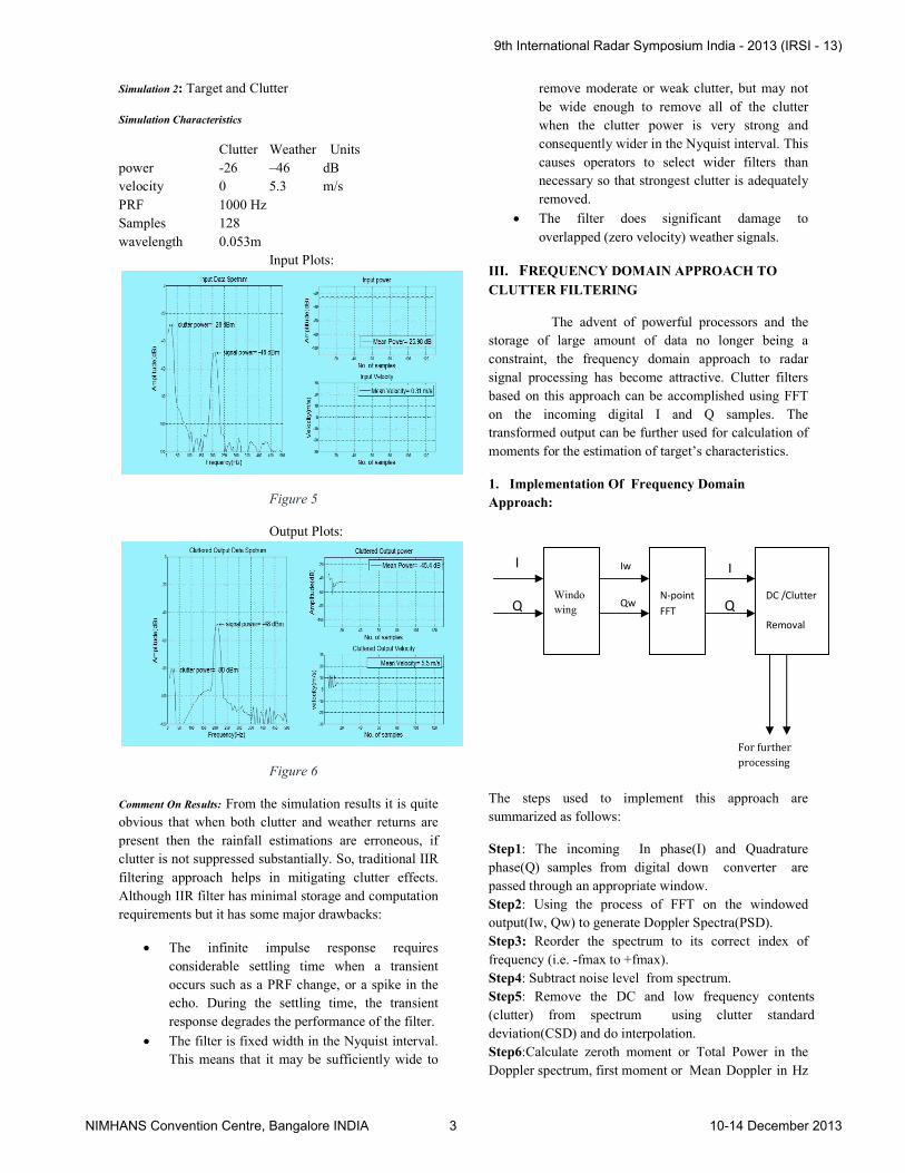
Simulation 2: Target and Clutter
Simulation Characteristics
Clutter Weather Units
power -26 –46 dB
velocity 0 5.3 m/s
PRF 1000 Hz
Samples 128
wavelength 0.053m
Input Plots:
Figure 5
Output Plots:
Figure 6
Comment On Results: From the simulation results it is quite
obvious that when both clutter and weather returns are
present then the rainfall estimations are erroneous
clutter is not suppressed substantially. So, traditional IIR
filtering approach helps in mitigating clutt
Although IIR filter has minimal storage and computation
requirements but it has some major drawbacks:
The infinite impulse response requires
considerable settling time when a transient
occurs such as a PRF change, or a spike
echo. During the settling time, the transient
response degrades the performance of the filter.
The filter is fixed width in the Nyquist interval.
This means that it may be sufficiently wide to
Units
From the simulation results it is quite
obvious that when both clutter and weather returns are
rainfall estimations are erroneous, if
So, traditional IIR
filtering approach helps in mitigating clutter effects.
Although IIR filter has minimal storage and computation
requirements but it has some major drawbacks:
nite impulse response requires
settling time when a transient
occurs such as a PRF change, or a spike in the
the settling time, the transient
response degrades the performance of the filter.
The filter is fixed width in the Nyquist interval.
This means that it may be sufficiently wide to
remove moderate or weak clutter, but may not
be wide enough to remove all o
when the clutter power is very strong and
consequently wider in the Nyquist interval. This
causes operators to select wider filters than
necessary so that strongest clutter is adequately
removed.
The filter does significant damage to
overlapped (zero velocity) weather signals
III. FREQUENCY DOMAIN APPROACH TO
CLUTTER FILTERING
The advent of powerful processors and
storage of large amount of data no longer being a
constraint, the frequency domain approach to radar
signal processing has become attractive. Clutter filters
based on this approach can be accomplished using FFT
on the incoming digital I and Q samples. The
transformed output can be further used for calculation of
moments for the estimation of target’s char
1. Implementation Of Frequency Domain
Approach:
The steps used to implement this approach are
summarized as follows:
Step1: The incoming In phase(I) and Quadrature
phase(Q) samples from digital
passed through an appropriate window.
Step2: Using the process of FFT on the windowed
output(Iw, Qw) to generate Doppler Spectra(PSD).
Step3: Reorder the spectrum to its correct index of
frequency (i.e. -fmax to +fmax).
Step4: Subtract noise level from spectrum.
Step5: Remove the DC and low frequency
(clutter) from spectrum using clutter
deviation(CSD) and do interpolation.
Step6:Calculate zeroth moment or Total Power in the
Doppler spectrum, first moment or
Q
I Iw
Qw
Windo
wing
N-point
FFT
remove moderate or weak clutter, but may not
be wide enough to remove all of the clutter
when the clutter power is very strong and
consequently wider in the Nyquist interval. This
causes operators to select wider filters than
necessary so that strongest clutter is adequately
The filter does significant damage to
ed (zero velocity) weather signals.
REQUENCY DOMAIN APPROACH TO
powerful processors and the
storage of large amount of data no longer being a
constraint, the frequency domain approach to radar
signal processing has become attractive. Clutter filters
based on this approach can be accomplished using FFT
on the incoming digital I and Q samples. The
transformed output can be further used for calculation of
moments for the estimation of target’s characteristics.
Implementation Of Frequency Domain
The steps used to implement this approach are
: The incoming In phase(I) and Quadrature
phase(Q) samples from digital down converter are
passed through an appropriate window.
Using the process of FFT on the windowed
output(Iw, Qw) to generate Doppler Spectra(PSD).
Reorder the spectrum to its correct index of
Subtract noise level from spectrum.
: Remove the DC and low frequency contents
(clutter) from spectrum using clutter standard
ation.
Calculate zeroth moment or Total Power in the
Doppler spectrum, first moment or Mean Doppler in Hz
I
Q
For further
processing
point
DC /Clutter
Removal
9th International Radar Symposium India - 2013 (IRSI - 13)
NIMHANS Convention Centre, Bangalore INDIA 3 10-14 December 2013

and second moment or Variance using spectrum
obtained from Step 5.
2. Simulation Results:In order to illustrate the
effectiveness of FFT filtering approach on clutter
suppression, we have simulated target plus clutter in
MATLAB and results are as shown below.
Simulation: Target and Clutter
Simulation Characteristics
Clutter Weather Units
power -26 –46 dB
velocity 0 5.3 m/s
PRF 1000 Hz
Samples 128
wavelength 0.053m
Input Plots:
Figure 7
Output Plots:
Figure 8
Comment On Results: Using an appropriate window
is very important to limit the effects of spectral leakage
and picket fence effects arising due to the application of
Fourier Transform on a finite data sequence. Side lobes
using spectrum
In order to illustrate the
filtering approach on clutter
suppression, we have simulated target plus clutter in
MATLAB and results are as shown below.
Using an appropriate window
is very important to limit the effects of spectral leakage
and picket fence effects arising due to the application of
Fourier Transform on a finite data sequence. Side lobes
reduction generated in the spectra due to discontinu
at the ends of the signal measurement time will interfere
in the accurate estimation of moments after the Fourier
Transform. Hence, windowing must be done to reduce
such effects. But, one must be careful with the choice of
window, as it can be too aggressive or mild. A very
aggressive window can suppress signals even in
environments where there is little or no clutter whereas a
mild filter can prove to be ineffective in reducing side
lobes of in the presence of heavy clutter. Also, there is
trade-off between a narrow bandwidth window function
and side-lobe reductions. Ideally we would want a
windowing function that has a very narrow bandwidth
and strong side-lobe rejection.
Although FFT filtering approach requires more
resources than IIR approach but it shows drastic
improvement over some of the
approach:
The FFT filtering allows for better target
frequency determination and immunity from
clutter as we are only interested in t
bin that can be easily discernible once the
clutter has been neutralized as mentioned
above. This also does not suffer from the phase
non-linearity of an IIR filter’s transition zone.
Also, it is not plagued by the long settling time
of the IIR filter response.
The filtering of clutter represented by a sharp
peak on the zero frequency regions is
performed by removing the peaks and
interpolating across the 0Hz region of the
resultant Power Spectra ,due to this overlapped
(zero velocity) weather si
significant damage.
3. Limitation of FFT approach:
The most significant limitation arises from the
limited number of samples that is available for
the spectral analysis. If we regard the FFT as
equivalent to a series of filters centered on each
spectral sample, the width of each of these
filters is limited by the Pulse Repetition
Frequency(PRF) and the number of FFT
points(N).
Fbin=PRF/N
The limitation in the resolution of each of the
FFT filters results in the maximum absolute
error of Fbin/2 in the det
frequency of the target .
large and the samples are small in number, then
reduction generated in the spectra due to discontinuities
at the ends of the signal measurement time will interfere
in the accurate estimation of moments after the Fourier
windowing must be done to reduce
such effects. But, one must be careful with the choice of
gressive or mild. A very
aggressive window can suppress signals even in
environments where there is little or no clutter whereas a
mild filter can prove to be ineffective in reducing side
lobes of in the presence of heavy clutter. Also, there is
between a narrow bandwidth window function
lobe reductions. Ideally we would want a
windowing function that has a very narrow bandwidth
ing approach requires more
resources than IIR approach but it shows drastic
some of the drawbacks of IIR
The FFT filtering allows for better target
frequency determination and immunity from
clutter as we are only interested in the peaking
bin that can be easily discernible once the
clutter has been neutralized as mentioned
above. This also does not suffer from the phase
linearity of an IIR filter’s transition zone.
Also, it is not plagued by the long settling time
filter response.
The filtering of clutter represented by a sharp
peak on the zero frequency regions is
performed by removing the peaks and
interpolating across the 0Hz region of the
resultant Power Spectra ,due to this overlapped
(zero velocity) weather signals don't suffer
Limitation of FFT approach:
The most significant limitation arises from the
limited number of samples that is available for
the spectral analysis. If we regard the FFT as
equivalent to a series of filters centered on each
spectral sample, the width of each of these
d by the Pulse Repetition
Frequency(PRF) and the number of FFT
points(N).
Fbin=PRF/N
The limitation in the resolution of each of the
FFT filters results in the maximum absolute
error of Fbin/2 in the determination of
Naturally if the PRF is
large and the samples are small in number, then
9th International Radar Symposium India - 2013 (IRSI - 13)
NIMHANS Convention Centre, Bangalore INDIA 4 10-14 December 2013
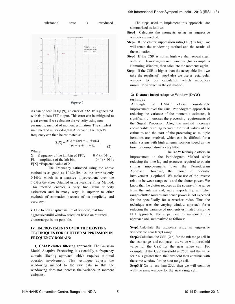
substantial error is introduced.
Figure 9
As can be seen in fig (9), an error of 7.65Hz is generated
with 64 pulses FFT output. This error can be mitigated to
great extent if we calculate the velocity using non
parametric method of moment estimation. The simplest
such method is Periodogram Approach. The target’s
frequency can then be estimated as
Where, X =frequency of the kth bin of FFT, Pk =amplitude of the kth bin, E[X] =Expected value of X, The Frequency estimated using the above
method is as good as 101.24Hz, i.e. the error is only
0.16Hz which is a massive improvement over the
7.65Hz,the error obtained using Peaking Filter Method.
This method enables a very fine grain velocity
estimation and in many ways is superior to other
methods of estimation because of its simplicity and
accuracy.
Due to non adaptive nature of window, real time
aggressive/mild window selection based on returned
clutter/target is not possible.
IV. IMPROVEMENTS OVER THE EXISTING
TECHNIQUES FOR CLUTTER SUPPRESSION IN
FREQUENCY DOMAIN:
1) GMAP clutter filtering approach:
Model Adaptive Processing is essentially a frequency
domain filtering approach which requires minimal
operator involvement. This technique adjusts the
windowing method to the raw data so that the
windowing does not increase the variance in mo
estimates.
substantial error is introduced.
), an error of 7.65Hz is generated
with 64 pulses FFT output. This error can be mitigated to
great extent if we calculate the velocity using non-
parametric method of moment estimation. The simplest
odogram Approach. The target’s
(2)
0 ≤ k ≤ N-1; 0 ≤ k ≤ N-1;
The Frequency estimated using the above
the error is only
0.16Hz which is a massive improvement over the
7.65Hz,the error obtained using Peaking Filter Method.
a very fine grain velocity
estimation and in many ways is superior to other
methods of estimation because of its simplicity and
real time
based on returned
IMPROVEMENTS OVER THE EXISTING
TECHNIQUES FOR CLUTTER SUPPRESSION IN
The Gaussian
Model Adaptive Processing is essentially a frequency
domain filtering approach which requires minimal
operator involvement. This technique adjusts the
windowing method to the raw data so that the
windowing does not increase the variance in moment
The steps used to implement this approach
summarized as follows:
Step1: Calculate the moments using an aggressive
windowing method.
Step2: If the clutter suppression ratio(CSR) is hig
will retain the windowing method and th
the estimation.
Step3: If the CSR is not as high we shall repeat step
with a lesser aggressive window ,for example a
Hamming Window, then calculate the moments
Step4: If the CSR is higher than the acceptable limit we
take the results of step3,else we use a rectangular
window for our calculation which introduces
minimum variance in the estimation.
2) Distance based Adaptive Window (DAW)
technique
Although the GMAP offers considerable
improvement over the usual Periodogram approach in
reducing the variance of the moment’s estimates, it
significantly increases the processing requirements of
the Signal Processor. Also, the method increases
considerable time lag between the final values of the
estimates and the start of the processing as multiple
iterations are involved, which can be difficult for a
radar system with high antenna rotation speed as the
time for computation is very little.
The DAW te
improvement to the Periodogram Method while
reducing the time lag and resources required to obtain
similar improvements over the Periodogram
Approach. However, the choice of operator
involvement is optional. We make use of the inverse
relation between range cells and the clutter power. We
know that the clutter reduces as the square of the range
from the antenna and, more importantly, at higher
ranges clutter sources and hence power is not expected
for the specifically for a weather radar.
technique uses the varying window approach for a
reducing the variance of moments estimated using the
FFT approach. The steps used to implement this
approach are summarized as follows:
Step1:Calculate the moments using an aggressive
window for near target range.
Step2:Calculate the CSR (Xn) for the nth range cell in
the near range and compare the value with threshold
value for the CSR for the near range cell. For
example, if the CSR threshold is 25db and t
for Xn is greater than the threshold then continue with
the same window for the next range cell.
Step3:If Xn is less than 25db then we will continue
with the same window for the next range cell.
The steps used to implement this approach are
: Calculate the moments using an aggressive
: If the clutter suppression ratio(CSR) is high, we
method and the results of
: If the CSR is not as high we shall repeat step1
with a lesser aggressive window ,for example a
en calculate the moments again.
: If the CSR is higher than the acceptable limit we
,else we use a rectangular
window for our calculation which introduces
minimum variance in the estimation.
Distance based Adaptive Window (DAW)
Although the GMAP offers considerable
improvement over the usual Periodogram approach in
reducing the variance of the moment’s estimates, it
significantly increases the processing requirements of
the Signal Processor. Also, the method increases
le time lag between the final values of the
estimates and the start of the processing as multiple
iterations are involved, which can be difficult for a
radar system with high antenna rotation speed as the
time for computation is very little.
The DAW technique offers an
improvement to the Periodogram Method while
reducing the time lag and resources required to obtain
similar improvements over the Periodogram
Approach. However, the choice of operator
involvement is optional. We make use of the inverse
ation between range cells and the clutter power. We
know that the clutter reduces as the square of the range
from the antenna and, more importantly, at higher
ranges clutter sources and hence power is not expected
for the specifically for a weather radar. Thus the
technique uses the varying window approach for a
reducing the variance of moments estimated using the
The steps used to implement this
approach are summarized as follows:
Calculate the moments using an aggressive
Calculate the CSR (Xn) for the nth range cell in
the value with threshold
SR for the near range cell. For
example, if the CSR threshold is 25db and the value
threshold then continue with
the same window for the next range cell.
If Xn is less than 25db then we will continue
next range cell.
9th International Radar Symposium India - 2013 (IRSI - 13)
NIMHANS Convention Centre, Bangalore INDIA 5 10-14 December 2013

Step4:If the CSR calculated has been less than the
threshold CSR for consecutive number of range cells
(say for 5 cells), then switch to a moderate
windowing method with much lesser variation in
moments.
Step5:Repeat steps 2,3 and 4 for the moderate window
with consequent transition towards a lesser aggressive
window till we arrive at the rectangular window. It
must be noted that the choice of threshold can rest
with the operator or it can be incorporated in the
algorithm as standard values. The number of
comparisons before switching the windowing method
can once again be operator controlled ,however this
ensures a smoother transition of the window and
overcome the “one-off” CSR reduction for any range
cell
3) Spectrum Edge Effect:The FFT based moments
calculation is much simpler than the time domain
approach in terms of the ease of clutter filtering and
the flexibility involved once the FFT of the I and Q
data is obtained. However, the nature of FFT spectra
so obtained introduces effects that hinders the accurate
calculation of moments. The most notorious of them is
what we call as the Spectrum Edge Effect.An
observation of the Spectrum of the Weather data
reveals that the return target spreads over several FFT
bins and if it happens to be of a higher velocity (close
to PRF/2), it can spill over to the negative spectrum
which gives an unacceptable velocity estimate of the
return target. This is particularly severe when the
number of pulses are limited which is typical of a
sophisticated modern day weather radars. Since, the
mean Doppler frequency shift is calculated making use
of the entire spectra with the respective power of each
range cell acting as the weight for each range bin. So
the high velocity estimates are severely compromised
because of the greater power spillage towards the
negative spectrum when the frequency of the Doppler
is closer to the Nyquist frequency for a given PRF.
To overcome this problem we make
use of the initial assumption of the radar clutter that
the clutter returns are mostly stationary and their
effects are concentrated around the DC line of the
frequency spectrum. Hence, the effect of clutter at a
higher velocity is often negligible.
The method involves the calculation of
unfiltered Doppler velocity in the time domain of the
incoming radar returns. This velocity may not be
correct for lower Doppler frequency shifts but are
reasonable accurate for higher dopplers. We compare
the frequency estimates after FFT with the unfiltered
frequency estimate obtained in the Time domain if the
calculated estimate is greater than Nyquist frequency/2
to avoid unnecessary comparisons. If the estimates
vary greatly, if throw the estimate of the FFT method
and take the frequency value of the unfiltered data.
This can effectively solve the problems arising due to
the Power spillage and restore the credibility of the
values so calculated.
CONCLUSION:
The clutter mitigation techniques have evolved
continuously over last decade or two and with the
effective employment of techniques like FFT and
GMAP and the virtually unlimited processing, storage
capacity and speed of the modern day processors, the
technology is sure to reach unprecedented heights over
the next decade.
REFERENCES:
[1].Clutter(radar)Source:http://en.wikipedia.org/w/index.php?oldid=
564538671 [2]. Principles of modern radar, basic principles Mark
A. Richards, James A. Scheer, William A. Holm
[3]. Characteristics of Different Smoothing Windows, National
Instruments
[4]. Nonparametric Estimation of Mean Doppler and Spectral
Width José M. B. Dias, Member, IEEE, and José M. N. Leitão,
Member, IEEE
[5] Clutter Filtering and Spectral Moment Estimation for Doppler
Weather Radars Using Staggered Pulse Repetition Time (PRT)M.
SACHIDANANDA,D. S. ZRNIC .́
[6] Doppler Radar And Weather Observations Richard J. Doviak
and Dusan S. Zrnic 2nd Edition.
BIO DATA OF AUTHOR(S)
Shashi Ranjan Kumar (Senior Engineer)
completed his B. E. degree from Muzaffarpur
Institute of Technology under B.R.A University,
Bihar. He joined BEL in September 2007, and
currently developing Digital Receiver for X-band
Conventional Tracking Radar in C-D&E-RSP core group. He was
also involved in development and design of S- Band DWR Digital
receiver, C- Band DWR Signal Processor and Signal processor for
Low Probability of Intercept(LPI) Radar.
Rahul Ranjan (Deputy Engineer) completed his B. Tech. degree from B.I.T. Sindri under Vinoba Bhave University, Jharkhand. He joined Bharat Electronics in December 2010, and currently developing Digital Receiver for X-band Conventional Tracking Radar in C-D&E-Radar
Signal Processing core group. He was also involved in development and design C- Band DWR Signal Processor. Prior to joining BEL he worked as an automation and control engineer for JSW ISPAT India Limited, Mumbai.
Malwinder Singh(Deputy Engineer) completed
his B. Tech. degree from Thapar University,
Punjab. He joined Bharat Electronics in December
2010, and currently developing Digital Receiver for
X-band Conventional Tracking Radar in C-D&E-
Radar Signal Processing core group. He was also
involved in development and design C- Band DWR
Signal Processor. Prior to joining BEL he worked as an application
engineer for Infogain India Private Limited.
9th International Radar Symposium India - 2013 (IRSI - 13)
NIMHANS Convention Centre, Bangalore INDIA 6 10-14 December 2013