Circuit Protection ACW - Tier1Automation.com · Circuit Protection The WEG ACW Series of Molded...
37
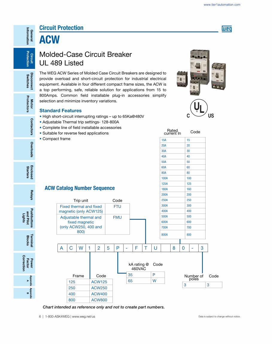
Appendix A Appendix B 6 | 1-800-ASK4WEG | www.weg.net/us General Information Circuit Protection Disconnect Switches Motor Protectors Overloads Relays Pushbuttons and Pilot Lights Terminal Blocks Contactors Power Factor Correction Enclosed Starters Data is subject to change without notice. Circuit Protection The WEG ACW Series of Molded Case Circuit Breakers are designed to provide overload and short-circuit protection for industrial electrical equipment. Available in four different compact frame sizes, the ACW is a top performing, safe, reliable solution for applications from 15 to 800Amps. Common field installable plug-in accessories simplify selection and minimize inventory variations. Standard Features • High short-circuit interrupting ratings – up to 65Ka@480V • Adjustable Thermal trip settings- 128-800A • Complete line of field installable accessories • Suitable for reverse feed applications • Compact frame ACW Molded-Case Circuit Breaker UL 489 Listed ACW Catalog Number Sequence Rated current In Code 15A 15 20A 20 30A 30 40A 40 50A 50 60A 60 80A 80 100A 100 125A 125 160A 160 200A 200 250A 250 300A 300 400A 400 500A 500 600A 600 700A 700 800A 800 A C W 1 2 5 P - F T U 8 0 - 3 Number of poles Code 3 3 Trip unit Code Fixed thermal and fixed magnetic (only ACW125) FTU Adjustable thermal and fixed magnetic (only ACW250, 400 and 800) FMU Frame Code 125 ACW125 250 ACW250 400 ACW400 800 ACW800 kA rating @ 460VAC Code 35 P 65 W Chart intended as reference only and not to create part numbers. www.tier1automation.com
Transcript of Circuit Protection ACW - Tier1Automation.com · Circuit Protection The WEG ACW Series of Molded...
Ap
pe
nd
ix
A
Ap
pe
nd
ix
B
6 | 1-800-ASK4WEG | www.weg.net/us
Ge
ne
ral
Info
rma
tion
Circ
uit
Pro
tec
tion
Dis
co
nn
ec
t
Sw
itch
es
Mo
tor
Pro
tec
tors
Ove
rloa
ds
Re
lays
Pu
sh
bu
tton
s
an
d P
ilot
Lig
hts
Te
rmin
al
Blo
ck
s
Co
nta
cto
rsP
ow
er
Fa
cto
r
Co
rrec
tion
En
clo
se
d
Sta
rters
Data is subject to change without notice.
Circuit Protection
The WEG ACW Series of Molded Case Circuit Breakers are designed to provide overload and short-circuit protection for industrial electrical equipment. Available in four different compact frame sizes, the ACW is a top performing, safe, reliable solution for applications from 15 to 800Amps. Common fi eld installable plug-in accessories simplify selection and minimize inventory variations.
Standard Features
• High short-circuit interrupting ratings – up to 65Ka@480V• Adjustable Thermal trip settings- 128-800A• Complete line of field installable accessories• Suitable for reverse feed applications• Compact frame
ACW
Molded-Case Circuit BreakerUL 489 Listed
ACW Catalog Number Sequence
Rated current In Code
15A 15
20A 20
30A 30
40A 40
50A 50
60A 60
80A 80
100A 100
125A 125
160A 160
200A 200
250A 250
300A 300
400A 400
500A 500
600A 600
700A 700
800A 800
A C W 1 2 5 P - F T U 8 0 - 3
Number of poles
Code
3 3
Trip unit Code
Fixed thermal and fi xed magnetic (only ACW125)
FTU
Adjustable thermal and fi xed magnetic
(only ACW250, 400 and 800)
FMU
Frame Code
125 ACW125
250 ACW250
400 ACW400
800 ACW800
kA rating @ 460VAC
Code
35 P
65 W
Chart intended as reference only and not to create part numbers.
www.tier1automation.com

Ap
pe
nd
ix
A
Ap
pe
nd
ix
B
Po
we
r
Fa
cto
r
Co
rre
cti
on
Te
rmin
al
Blo
ck
s
Pu
sh
bu
tto
ns
an
d P
ilo
t
Lig
hts
Ove
rlo
ad
sC
on
tac
tors
Mo
tor
Pro
tec
tors
Dis
co
nn
ec
t
Sw
itc
he
s
Re
lays
Cir
cu
it
Pro
tec
tio
n
Ge
ne
ral
Info
rma
tio
n
En
clo
se
d
Sta
rte
rs
WEG Automation - Products and Solutions | 7Data is subject to change without notice.
Circuit Protection
ACW
Ap
pe
nd
ix
A
Ap
pe
nd
ix
B
MCCB for power distribution - standard interrupting capacity
ACW125P - FTU trip unit – Fixed thermal and fi xed magnetic
ACW250P - FMU trip unit – Adjustable thermal and fi xed magnetic
ACW400P - FMU trip unit – Adjustable thermal and fi xed magnetic
ACW800P - FMU trip unit – Adjustable thermal and fi xed magnetic
Thermal Setting Magnetic Setting Short-Circuit interrupting capacityCatalog Number List Price Multiplier
[A] [A] 480VAC 600VAC
15 400
35kA 10kA
ACW125P-FTU15-3 $665
Z10
20 400 ACW125P-FTU20-3 $665
30 400 ACW125P-FTU30-3 $665
40 400 ACW125P-FTU40-3 $665
50 500 ACW125P-FTU50-3 $665
60 600 ACW125P-FTU60-3 $665
80 800 ACW125P-FTU80-3 $728
100 1000 ACW125P-FTU100-3 $728
125 1250 ACW125P-FTU125-3 $1,499
Note: Wiring terminal (lugs) not included. Lugs are available as accessory at page 14.
Note: Wiring terminal (lugs) not included. Lugs are available as accessory at page 14.
Thermal Setting Magnetic Setting Short-Circuit interrupting capacityCatalog Number List Price Multiplier
[A] [A] 480VAC 600VAC
128...160 160035kA 10kA
ACW250P-FMU160-3 $1,550
Z10160...200 2000 ACW250P-FMU200-3 $1,550
200...250 2500 ACW250P-FMU250-3 $1,550
Thermal Setting Magnetic Setting Short-Circuit interrupting capacityCatalog Number List Price Multiplier
[A] [A] 480VAC 600VAC
400...500 500035kA 18kA
ACW800P-FMU500-3 $4,757
Z10480...600 6000 ACW800P-FMU600-3 $4,757
640...800 8000 ACW800P-FMU800-3 $5,393
Thermal Setting Magnetic Setting Short-Circuit interrupting capacityCatalog Number List Price Multiplier
[A] [A] 480VAC 600VAC
240...300 300035kA 14kA
ACW400P-FMU300-3 $2,505Z10
320...400 4000 ACW400P-FMU400-3 $2,505
Note: WEG is committed to maintain stock for immediate delivery of the following trip units: FTU – ACW125P and ACW125W FMU – ACW250P, ACW250W, ACW400P, ACW400W, ACW800P, ACW800WPlease contact your WEG representative offi ce for availability of other trip units.
Note: Lugs for ACW400 are factory mounted.
Note: Lugs for ACW800 are factory mounted.
www.tier1automation.com

Ap
pe
nd
ix
A
Ap
pe
nd
ix
B
Ge
ne
ral
Info
rma
tion
Circ
uit
Pro
tec
tion
Dis
co
nn
ec
t
Sw
itch
es
Mo
tor
Pro
tec
tors
Ove
rloa
ds
Re
lays
Pu
sh
bu
tton
s
an
d P
ilot
Lig
hts
Te
rmin
al
Blo
ck
s
Co
nta
cto
rsP
ow
er
Fa
cto
r
Co
rrec
tion
En
clo
se
d
Sta
rters
Data is subject to change without notice.
Circuit Protection
ACW
8 | 1-800-ASK4WEG | www.weg.net/us
MCCB for power distribution - high interrupting capacity
Note: Wiring terminal (lugs) not included. Lugs are available as accessory at page 14.
ACW125W - FTU trip unit – Fixed thermal and fi xed magnetic
Thermal Setting Magnetic Setting Short-Circuit interrupting capacityCatalog Number List Price Multiplier
[A] [A] 480VAC 600VAC
15 400
65kA 14kA
ACW125W-FTU15-3 $965
Z10
20 400 ACW125W-FTU20-3 $965
30 400 ACW125W-FTU30-3 $965
40 400 ACW125W-FTU40-3 $965
50 500 ACW125W-FTU50-3 $965
60 600 ACW125W-FTU60-3 $965
80 800 ACW125W-FTU80-3 $1,055
100 1000 ACW125W-FTU100-3 $1,055
125 1250 ACW125W-FTU125-3 $2,101
Note: Wiring terminal (lugs) not included. Lugs are available as accessory at page 14.
ACW250W - FMU trip unit – Adjustable thermal and fi xed magnetic
Thermal Setting Magnetic Setting Short-Circuit interrupting capacityCatalog Number List Price Multiplier
[A] [A] 480VAC 600VAC
128...160 160065kA 18kA
ACW250W-FMU160-3 $2,826
Z10160...200 2000 ACW250W-FMU200-3 $2,826
200...250 2500 ACW250W-FMU250-3 $2,826
Note: WEG is committed to maintain stock for immediate delivery of the following trip units: FTU – ACW125P and ACW125W FMU – ACW250P, ACW250W, ACW400P, ACW400W, ACW800P, ACW800WPlease contact your WEG representative offce for availability of other trip units.
ACW400W - FMU trip unit – Adjustable thermal and fi xed magnetic
Thermal Setting Magnetic Setting Short-Circuit interrupting capacityCatalog Number List Price Multiplier
[A] [A] 480VAC 600VAC
240...300 300065kA 20kA
ACW400W-FMU300-3 $4,312Z10
320...400 4000 ACW400W-FMU400-3 $4,312
Note: Lugs for ACW400 are factory mounted.
ACW800W - FMU trip unit – Adjustable thermal and fi xed magnetic
Thermal Setting Magnetic Setting Short-Circuit interrupting capacityCatalog Number List Price Multiplier
[A] [A] 480VAC 600VAC
400...500 500065kA 25kA
ACW800W-FMU500-3 $6,392
Z10480...600 6000 ACW800W-FMU600-3 $6,392
640...800 8000 ACW800W-FMU800-3 $7,358
Note: Lugs for ACW800 are factory mounted.
www.tier1automation.com

Ap
pe
nd
ix
A
Ap
pe
nd
ix
B
Po
we
r
Fa
cto
r
Co
rre
cti
on
Te
rmin
al
Blo
ck
s
Pu
sh
bu
tto
ns
an
d P
ilo
t
Lig
hts
Ove
rlo
ad
sC
on
tac
tors
Mo
tor
Pro
tec
tors
Dis
co
nn
ec
t
Sw
itc
he
s
Re
lays
Cir
cu
it
Pro
tec
tio
n
Ge
ne
ral
Info
rma
tio
n
En
clo
se
d
Sta
rte
rs
WEG Automation - Products and Solutions | 9Data is subject to change without notice.
Circuit Protection
ACW
Ap
pe
nd
ix
A
Ap
pe
nd
ix
B
Internal accessories
Auxiliary contact
Suitable for Catalog Number List Price Multiplier
ACW125...800 AX ACW 125-800 $103 Z10
ACW ON OFF TRIP
Auxiliary contact AXc1AXa1
AXc1AXa1
AXb1 AXb1
The auxiliary contact block contains one set of form ‘C’ contacts. This contact indicates remote circuit-breaker status “ON” and “OFF”.
Alarm contact
Suitable for Catalog Number List Price Multiplier
ACW125...800 AL ACW 125-800 $103 Z10
ACW ON OFF TRIP
Alarm contact ALc1Ala1
ALc1Ala1
ALb1 ALb1
Alarm contact offers provisions for audio and visual indication of a tripped breaker due to overload, short-circuit, shunt trip or under voltage release conditions. The contact opens when the circuit breaker is reset.
Shunt release
Suitable for Rated voltage Catalog Number List Price Multiplier
ACW125...800
12VDC SHT C02 ACW 125-800 $235
Z10
24VAC/DC SHT E26 ACW 125-800 $235
48VAC/DC SHT E27 ACW 125-800 $235
110-130VAC/DC SHT E10 ACW 125-800 $235
220-240VAC/250VDC SHT E14 ACW 125-800 $235
380-500VAC SHT E52 ACW 125-800 $235
The shunt release opens the breaker in response to an externally voltage signal.
Range of operational voltage: 0.7…1.1xUnFrequency: 45…65Hz
www.tier1automation.com
Ap
pe
nd
ix
A
Ap
pe
nd
ix
B
Ge
ne
ral
Info
rma
tion
Circ
uit
Pro
tec
tion
Dis
co
nn
ec
t
Sw
itch
es
Mo
tor
Pro
tec
tors
Ove
rloa
ds
Re
lays
Pu
sh
bu
tton
s
an
d P
ilot
Lig
hts
Te
rmin
al
Blo
ck
s
Co
nta
cto
rsP
ow
er
Fa
cto
r
Co
rrec
tion
En
clo
se
d
Sta
rters
Data is subject to change without notice.
Circuit Protection
ACW
10 | 1-800-ASK4WEG | www.weg.net/us
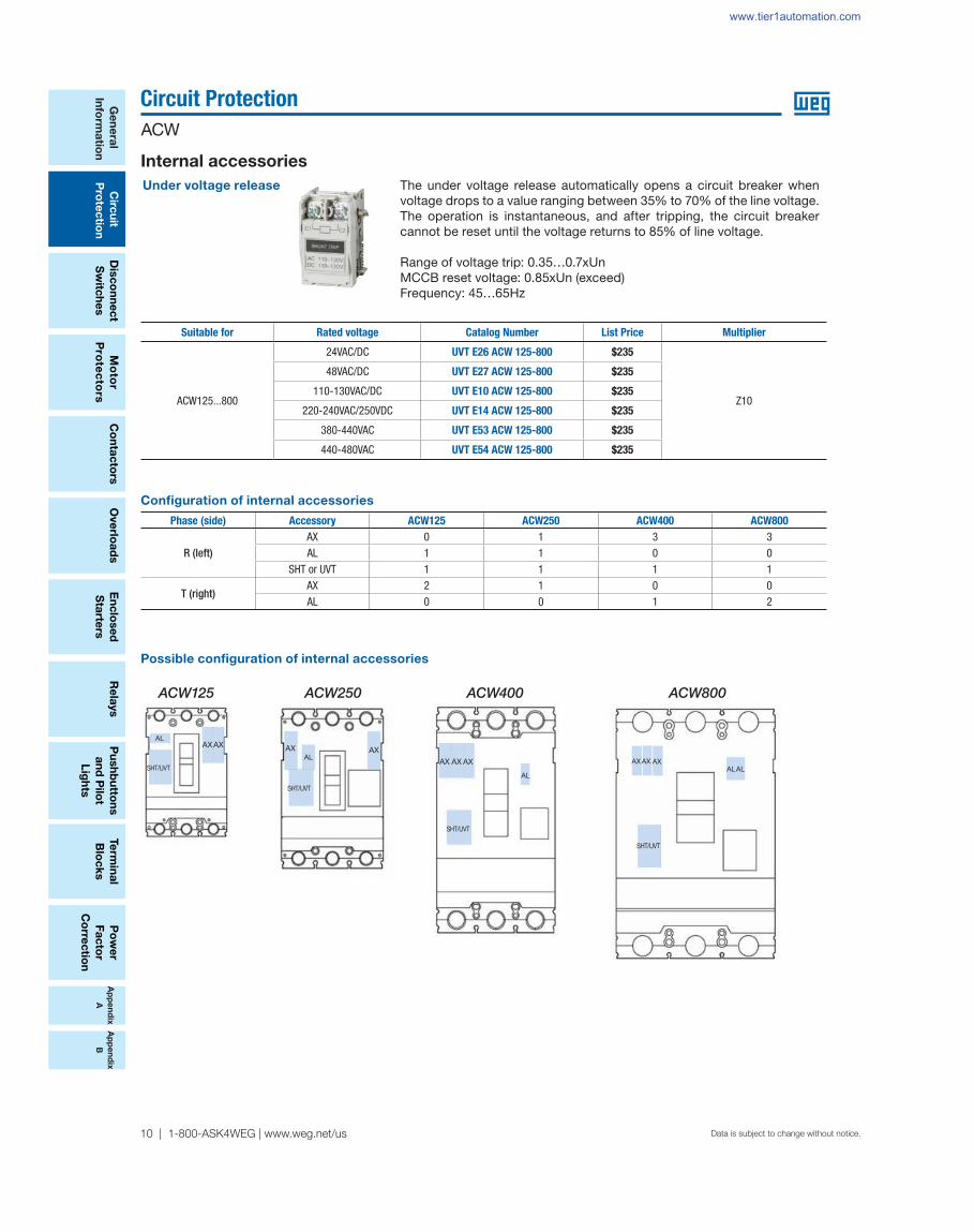
Under voltage release
Suitable for Rated voltage Catalog Number List Price Multiplier
ACW125...800
24VAC/DC UVT E26 ACW 125-800 $235
Z10
48VAC/DC UVT E27 ACW 125-800 $235
110-130VAC/DC UVT E10 ACW 125-800 $235
220-240VAC/250VDC UVT E14 ACW 125-800 $235
380-440VAC UVT E53 ACW 125-800 $235
440-480VAC UVT E54 ACW 125-800 $235
The under voltage release automatically opens a circuit breaker when voltage drops to a value ranging between 35% to 70% of the line voltage. The operation is instantaneous, and after tripping, the circuit breaker cannot be reset until the voltage returns to 85% of line voltage.
Range of voltage trip: 0.35…0.7xUnMCCB reset voltage: 0.85xUn (exceed)Frequency: 45…65Hz
Confi guration of internal accessories
Internal accessories
Phase (side) Accessory ACW125 ACW250 ACW400 ACW800
R (left)AX 0 1 3 3AL 1 1 0 0
SHT or UVT 1 1 1 1
T (right)AX 2 1 0 0AL 0 0 1 2
Possible confi guration of internal accessories
ACW125 ACW250 ACW400 ACW800
AXAX
SHT/UVT
AL
AX AX
SHT/UVT
ALAX AX AX
SHT/UVT
AL
SHT/UVT
ALALAX AX AX
www.tier1automation.com

Ap
pe
nd
ix
A
Ap
pe
nd
ix
B
Po
we
r
Fa
cto
r
Co
rre
cti
on
Te
rmin
al
Blo
ck
s
Pu
sh
bu
tto
ns
an
d P
ilo
t
Lig
hts
Ove
rlo
ad
sC
on
tac
tors
Mo
tor
Pro
tec
tors
Dis
co
nn
ec
t
Sw
itc
he
s
Re
lays
Cir
cu
it
Pro
tec
tio
n
Ge
ne
ral
Info
rma
tio
n
En
clo
se
d
Sta
rte
rs
WEG Automation - Products and Solutions | 11Data is subject to change without notice.
Circuit Protection
ACW
Ap
pe
nd
ix
A
Ap
pe
nd
ix
B
Rotary handle
External accessories
The through-the-door rotary handle operating mechanism is available in UL Type and 4X versions. Units are offered either complete (rotary handle + operating mechanism + shaft 12”) or as seperate components (different shaft sizes sold separately). Handle is Lockable in OFF or ON position & defeatable in ON position.
Rotary handle + mechanism + shaft 12“ (UL Type 4X)
Suitable for Catalog Number List Price Multiplier
ACW125 EHBX 12 ACW 125 $331
Z10ACW250 EHBX 12 ACW 250 $352
ACW400 EHBX 12 ACW 400 $422
ACW800 EHBX 12 ACW 800 $586
Rotary handle + mechanism (without shaft) (UL Type 4X)
Suitable for Catalog Number List Price Multiplier
ACW125 EHBX ACW 125 $305
Z10
ACW250 EHBX ACW 250 $322
ACW400 EHBX ACW 400 $398
ACW800 EHBX ACW 800 $575
16” shaft for rotary handle
ACW125…800 ES 16 ACW 125-800 $53
24” shaft for rotary handle
ACW125…800 ES 24 ACW 125-800 $71
www.tier1automation.com

Ap
pe
nd
ix
A
Ap
pe
nd
ix
B
Ge
ne
ral
Info
rma
tion
Circ
uit
Pro
tec
tion
Dis
co
nn
ec
t
Sw
itch
es
Mo
tor
Pro
tec
tors
Ove
rloa
ds
Re
lays
Pu
sh
bu
tton
s
an
d P
ilot
Lig
hts
Te
rmin
al
Blo
ck
s
Co
nta
cto
rsP
ow
er
Fa
cto
r
Co
rrec
tion
En
clo
se
d
Sta
rters
Data is subject to change without notice.
Circuit Protection
ACW
12 | 1-800-ASK4WEG | www.weg.net/us
Flange handle
External accessories
The fl ange disconnect handle is available in UL Type and 4X versions. Flexible cables are available in four different sizes (36”, 48”, 60”, 72”) and are ordered separately. Handle is Lockable in OFF position & defeatable in ON position.
Flange handle + mechanism (without fl exible cable) (UL Type 4X)
Suitable for Catalog Number List Price Multiplier
ACW125 FHX ACW 125 $458
Z10ACW250 FHX ACW 250 $526
ACW400 FHX ACW 400 $594
ACW800 FHX ACW 800 $656
Flexible Cable
Suitable for Catalog Number List Price Multiplier
Cable 36”
ACW125…250 FC 36 ACW 125-250 $146
Z10
ACW400…800 FC 36 ACW 400-800 $155
Cable 48”
ACW125…250 FC 48 ACW 125-250 $169
ACW400…800 FC 48 ACW 400-800 $179
Cable 60”
ACW125…250 FC 60 ACW 125-250 $188
ACW400…800 FC 60 ACW 400-800 $198
Cable 72”
ACW125…250 FC 72 ACW 125-250 $208
ACW400…800 FC 72 ACW 400-800 $227
ThFleareON
www.tier1automation.com

Ap
pe
nd
ix
A
Ap
pe
nd
ix
B
Po
we
r
Fa
cto
r
Co
rre
cti
on
Te
rmin
al
Blo
ck
s
Pu
sh
bu
tto
ns
an
d P
ilo
t
Lig
hts
Ove
rlo
ad
sC
on
tac
tors
Mo
tor
Pro
tec
tors
Dis
co
nn
ec
t
Sw
itc
he
s
Re
lays
Cir
cu
it
Pro
tec
tio
n
Ge
ne
ral
Info
rma
tio
n
En
clo
se
d
Sta
rte
rs
WEG Automation - Products and Solutions | 13Data is subject to change without notice.
Circuit Protection
ACW
Ap
pe
nd
ix
A
Ap
pe
nd
ix
B
Pad lock
Handle lock
External accessoriesThe padlock allows the handle to be locked in the “OFF” position. Maximum three padlocks with shackle diameters ranging from 0.2 to 0.3in (5 to 8mm) may be used. (Padlocks are not supplied)
Locking in the “OFF” position guarantee isolation required per UL 489.
The handle lock allows the handle to be locked in the “ON” and “OFF” positions. Maximum three padlocks with shackle diameters ranging from 0.2 to 0.3inch (5 to 8mm) may be used. (Padlocks are not supplied)
Locking in the “OFF” position guarantee isolation required per UL 489.
Suitable for Catalog Number List Price Multiplier
ACW125 PL ACW 125 $68
Z10ACW250 PL ACW 250 $75
ACW400 PL ACW 400 $90
ACW800 PL ACW 800 $100
Suitable for Catalog Number List Price Multiplier
ACW125 HL ACW 125 $105
Z10ACW250 HL ACW 250 $115
ACW400 HL ACW 400 $180
ACW800 HL ACW 800 $185
Pad lock
Handle lock
www.tier1automation.com

Ap
pe
nd
ix
A
Ap
pe
nd
ix
B
Ge
ne
ral
Info
rma
tion
Circ
uit
Pro
tec
tion
Dis
co
nn
ec
t
Sw
itch
es
Mo
tor
Pro
tec
tors
Ove
rloa
ds
Re
lays
Pu
sh
bu
tton
s
an
d P
ilot
Lig
hts
Te
rmin
al
Blo
ck
s
Co
nta
cto
rsP
ow
er
Fa
cto
r
Co
rrec
tion
En
clo
se
d
Sta
rters
Data is subject to change without notice.
Circuit Protection
ACW
14 | 1-800-ASK4WEG | www.weg.net/us
Wiring terminal (Lugs)
Mechanical interlock
External accessories
The mechanical interlock can be applied on the front of two breakers mounted side by side and prevents simultaneous closing of the two breakers. Interlock is assembled directly to the front cover of the breakers.
The interlocking plate allows installation of a padlock to maintain the position. The operator can lock out either one or both breakers in the “OFF” position. (Padlocks are not supplied)
Suitable for Catalog Number List Price Multiplier
ACW125 MIT ACW 125 $338
Z10ACW250 MIT ACW 250 $377
ACW400 MIT ACW 400 $413
ACW800 MIT ACW 800 $440
Suitable for Catalog Number List Price Multiplier
Set with 3 pieces
Z10
ACW125 LW1 3P ACW 125 $56
ACW250 LW2 3P ACW 250 $95
Set with 15 pieces
ACW125 LW1 15P ACW 125 $168
ACW250 LW2 15P ACW 250 $283
Line and Load terminals provide the means for connecting the circuit breaker to the power source and the load. Each breaker accepts up to 6 lugs (a set of 3 units for the line terminals and another set of 3 units for the load terminals); Each lug is suitable for either line or load terminals.
Frame TypeWire Range
"Conductor Cross-section” "Number of Conductors” Tightening Torque [lb.in.]
ACW12514 - 8 AWG 1 606 - 1/0 AWG 1 90
ACW250
1 AWG 1 1501/0 - 2/0 AWG 1 1803/0 - 4/0 AWG 1 250
250 - 300 kcmil 1 Tightening Torque 325
ACW400
250 - 400 kcmil 1 325500 kcmil 1 3753/0 AWG up to 2 250
ACW800 (500 and 600A) 250 - 500 kcmil up to 2 375
ACW800 (800A)250 - 400 kcmil up to 3 375
500 kcmil up to 2 375
Terminal size acceptability and terminal torque
www.tier1automation.com
Ap
pe
nd
ix
A
Ap
pe
nd
ix
B
Po
we
r
Fa
cto
r
Co
rre
cti
on
Te
rmin
al
Blo
ck
s
Pu
sh
bu
tto
ns
an
d P
ilo
t
Lig
hts
Ove
rlo
ad
sC
on
tac
tors
Mo
tor
Pro
tec
tors
Dis
co
nn
ec
t
Sw
itc
he
s
Re
lays
Cir
cu
it
Pro
tec
tio
n
Ge
ne
ral
Info
rma
tio
n
En
clo
se
d
Sta
rte
rs
WEG Automation - Products and Solutions | 15Data is subject to change without notice.
Circuit Protection
ACW
Ap
pe
nd
ix
A
Ap
pe
nd
ix
B
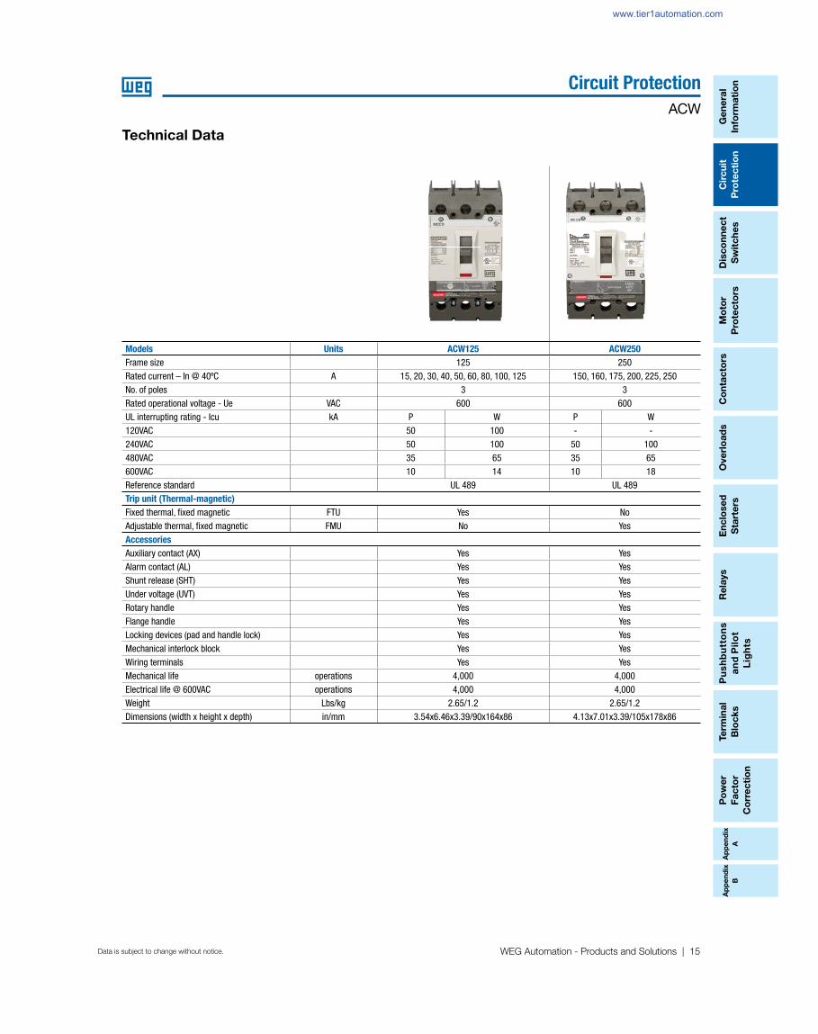
Technical Data
Models Units ACW125 ACW250
Frame size 125 250Rated current – In @ 40ºC A 15, 20, 30, 40, 50, 60, 80, 100, 125 150, 160, 175, 200, 225, 250No. of poles 3 3Rated operational voltage - Ue VAC 600 600UL interrupting rating - Icu kA P W P W120VAC 50 100 - -240VAC 50 100 50 100480VAC 35 65 35 65600VAC 10 14 10 18Reference standard UL 489 UL 489Trip unit (Thermal-magnetic)
Fixed thermal, fi xed magnetic FTU Yes NoAdjustable thermal, fi xed magnetic FMU No YesAccessories
Auxiliary contact (AX) Yes YesAlarm contact (AL) Yes YesShunt release (SHT) Yes YesUnder voltage (UVT) Yes YesRotary handle Yes YesFlange handle Yes YesLocking devices (pad and handle lock) Yes YesMechanical interlock block Yes YesWiring terminals Yes YesMechanical life operations 4,000 4,000Electrical life @ 600VAC operations 4,000 4,000Weight Lbs/kg 2.65/1.2 2.65/1.2Dimensions (width x height x depth) in/mm 3.54x6.46x3.39/90x164x86 4.13x7.01x3.39/105x178x86
www.tier1automation.com
Ap
pe
nd
ix
A
Ap
pe
nd
ix
B
Ge
ne
ral
Info
rma
tion
Circ
uit
Pro
tec
tion
Dis
co
nn
ec
t
Sw
itch
es
Mo
tor
Pro
tec
tors
Ove
rloa
ds
Re
lays
Pu
sh
bu
tton
s
an
d P
ilot
Lig
hts
Te
rmin
al
Blo
ck
s
Co
nta
cto
rsP
ow
er
Fa
cto
r
Co
rrec
tion
En
clo
se
d
Sta
rters
Data is subject to change without notice.
Circuit Protection
ACW
16 | 1-800-ASK4WEG | www.weg.net/us
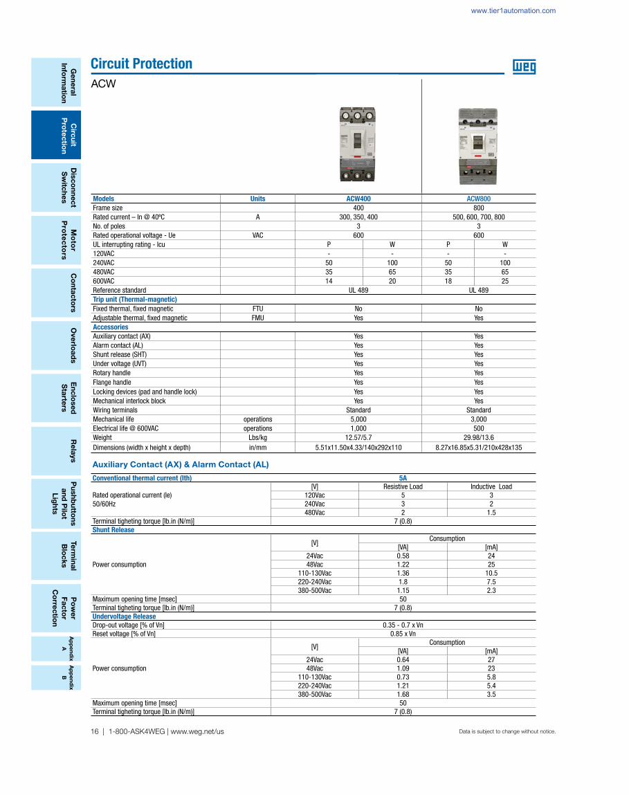
Auxiliary Contact (AX) & Alarm Contact (AL)
Conventional thermal current (Ith) 5A
Rated operational current (Ie) 50/60Hz
[V] Resistive Load Inductive Load120Vac 5 3240Vac 3 2480Vac 2 1.5
Terminal tigheting torque [lb.in (N/m)] 7 (0.8)Shunt Release
Power consumption
[V]Consumption
[VA] [mA]24Vac 0.58 2448Vac 1.22 25
110-130Vac 1.36 10.5220-240Vac 1.8 7.5380-500Vac 1.15 2.3
Maximum opening time [msec] 50Terminal tigheting torque [lb.in (N/m)] 7 (0.8)Undervoltage Release
Drop-out voltage [% of Vn] 0.35 - 0.7 x VnReset voltage [% of Vn] 0.85 x Vn
Power consumption
[V]Consumption
[VA] [mA]24Vac 0.64 2748Vac 1.09 23
110-130Vac 0.73 5.8220-240Vac 1.21 5.4380-500Vac 1.68 3.5
Maximum opening time [msec] 50Terminal tigheting torque [lb.in (N/m)] 7 (0.8)
Models Units ACW400 ACW800Frame size 400 800Rated current – In @ 40ºC A 300, 350, 400 500, 600, 700, 800No. of poles 3 3Rated operational voltage - Ue VAC 600 600UL interrupting rating - Icu P W P W120VAC - - - -240VAC 50 100 50 100480VAC 35 65 35 65600VAC 14 20 18 25Reference standard UL 489 UL 489Trip unit (Thermal-magnetic)
Fixed thermal, fi xed magnetic FTU No NoAdjustable thermal, fi xed magnetic FMU Yes YesAccessories
Auxiliary contact (AX) Yes YesAlarm contact (AL) Yes YesShunt release (SHT) Yes YesUnder voltage (UVT) Yes YesRotary handle Yes YesFlange handle Yes YesLocking devices (pad and handle lock) Yes YesMechanical interlock block Yes YesWiring terminals Standard StandardMechanical life operations 5,000 3,000Electrical life @ 600VAC operations 1,000 500Weight Lbs/kg 12.57/5.7 29.98/13.6Dimensions (width x height x depth) in/mm 5.51x11.50x4.33/140x292x110 8.27x16.85x5.31/210x428x135
www.tier1automation.com

Ap
pe
nd
ix
A
Ap
pe
nd
ix
B
Po
we
r
Fa
cto
r
Co
rre
cti
on
Te
rmin
al
Blo
ck
s
Pu
sh
bu
tto
ns
an
d P
ilo
t
Lig
hts
Ove
rlo
ad
sC
on
tac
tors
Mo
tor
Pro
tec
tors
Dis
co
nn
ec
t
Sw
itc
he
s
Re
lays
Cir
cu
it
Pro
tec
tio
n
Ge
ne
ral
Info
rma
tio
n
En
clo
se
d
Sta
rte
rs
WEG Automation - Products and Solutions | 17Data is subject to change without notice.
Circuit Protection
ACW
Ap
pe
nd
ix
A
Ap
pe
nd
ix
B
Screw and connection
Screw mounting
Connecting terminal and conductor
Terminal (mm) Conductor (mm)
ACW125
Max 78kgf·cm
ACW250
Max 147kgf·cm
18
8
23
22
M5x16
20
28
22
M8x20
>8>8
1025
21
2510
Models ACW125 ACW250 ACW400 ACW800
Screw for mounting
4EA(NO.8-32 UNC-2A, L100)
4EA(NO.10-24 UNC-2A, L120)
4EA(1/4”-20 UNC2A, L140)
Screw for connection of terminals
6EA(M5×L16) 6EA(M8×L20)
N.A. N.A.
Torque: Max 78kgf·cm
67.7lbf·in
Torque: Max 197kgf·cm
170lbf·inN.A. N.A.
Note: ACW400 and ACW800 are supplied with non-removable lugs.
Note: ACW400 and ACW800 are supplied with non-removable lugs.
www.tier1automation.com

Ap
pe
nd
ix
A
Ap
pe
nd
ix
B
Ge
ne
ral
Info
rma
tion
Circ
uit
Pro
tec
tion
Dis
co
nn
ec
t
Sw
itch
es
Mo
tor
Pro
tec
tors
Ove
rloa
ds
Re
lays
Pu
sh
bu
tton
s
an
d P
ilot
Lig
hts
Te
rmin
al
Blo
ck
s
Co
nta
cto
rsP
ow
er
Fa
cto
r
Co
rrec
tion
En
clo
se
d
Sta
rters
Data is subject to change without notice.
Circuit Protection
ACW
18 | 1-800-ASK4WEG | www.weg.net/us
MCCB Rating(A)
Fixed MCCB (thermal-magnetic trip unit)
50°F 68°F 86°F 104°F 122°F 140°F 158°F 176°F
10°C 20°C 30°C 40°C 50°C 60°C 70°C 80°C
ACW125
15 15 15 15 15 15 14 13 1220 20 20 20 20 19 19 18 16
30 30 30 30 30 29 28 26 24
40 40 40 40 40 39 38 35 3350 50 50 50 50 48 47 44 4160 60 60 60 60 58 56 53 4980 80 80 80 80 78 75 71 66100 100 100 100 100 97 94 88 82125 125 125 125 125 121 117 110 103
ACW250
150 150 150 150 150 145 140 131 121160 160 160 160 160 155 150 141 131175 175 175 175 175 170 165 156 145200 200 200 200 200 194 188 176 164225 225 225 225 225 219 213 201 189250 250 250 250 250 242 234 220 205
ACW400
300 300 300 300 300 291 281 264 246350 350 350 350 350 341 331 314 296400 400 400 400 400 388 375 353 328
ACW800
500 500 500 500 500 484 469 441 410600 600 600 600 600 580 571 525 487700 700 700 700 700 680 661 625 587800 800 800 800 800 775 750 705 656
A derating of the rated operational current for ACW series is necessary if the ambient temperature is greater than 40oC (+104oF), because the overload-protection characteristics are slightly modifi ed.
Temperature derating
UL interrupting rating (kA)
Current ratings
MCCB ACW125 ACW250 ACW400 ACW800
Type P W P W P W P W
@ 120V 50 100 - - - - - -
@ 240V 50 100 50 100 50 100 50 100
@ 480V 35 65 35 65 35 65 35 65
@ 600V 10 14 10 18 14 20 18 25
Models Rated Current In (A)
ACW125 15, 20, 30, 40, 50, 60, 80, 100, 125
ACW250 128-160, 160-200, 200-250
ACW400 240-300, 320-400
ACW800 400-500, 480-600, 640-800
www.tier1automation.com

Ap
pe
nd
ix
A
Ap
pe
nd
ix
B
Po
we
r
Fa
cto
r
Co
rre
cti
on
Te
rmin
al
Blo
ck
s
Pu
sh
bu
tto
ns
an
d P
ilo
t
Lig
hts
Ove
rlo
ad
sC
on
tac
tors
Mo
tor
Pro
tec
tors
Dis
co
nn
ec
t
Sw
itc
he
s
Re
lays
Cir
cu
it
Pro
tec
tio
n
Ge
ne
ral
Info
rma
tio
n
En
clo
se
d
Sta
rte
rs
WEG Automation - Products and Solutions | 19Data is subject to change without notice.
Circuit Protection
ACW
Ap
pe
nd
ix
A
Ap
pe
nd
ix
B
Cascading protection
Power supply 240V
Branch breakerMain breaker ACW125P ACW125W ACW250P ACW250W
Rated breaking capacity (kArms) 50 100 50 100
ACW125P 50 - 75 - 75ACW125W 100 - - - -ACW250P 50 - - - 75ACW250W 100 - - - -ACW400P 50 - - - -ACW400W 100 - - - -ACW800P 50 - - - -ACW800W 100 - - - -
Branch breakerMain breaker ACW400P ACW400W ACW800P ACW800W
Rated breaking capacity (kArms) 50 100 50 100
ACW125P 50 - 75 - 75ACW125W 100 - - - -ACW250P 50 - 75 - 75ACW250W 100 - - - -ACW400P 50 - 75 - 75ACW400W 100 - - - -ACW800P 50 - - - 75ACW800W 100 - - - -
Power supply 480V
Branch breakerMain breaker ACW125P ACW125W ACW250P ACW250W
Rated breaking capacity (kArms) 35 65 35 65
ACW125P 35 - 50 - 50ACW125W 65 - - - -ACW250P 35 - - - 50ACW250W 65 - - - -ACW400P 35 - - - -ACW400W 65 - - - -ACW800P 35 - - - -ACW800W 65 - - - -
Branch breakerMain breaker ACW400P ACW400W ACW800P ACW800W
Rated breaking capacity (kArms) 35 65 35 65
ACW125P 35 - 50 - 50ACW125W 65 - - - -ACW250P 35 - 50 - 50ACW250W 65 - - - -ACW400P 35 - 50 - 50ACW400W 65 - - - -ACW800P 35 - - - 50ACW800W 65 - - - -
This is an economical approach to the use of circuit protective devices, whereby only the main (upstream) breaker has adequate interrupting capacity for the maximum available fault current. Downstream circuit breakers cannot handle this maximum fault current and rely on the opening of the upstream breaker for protection.
The advantage of this approach is that it facilitates the use of downstream low cost, low fault level breakers, thereby offering savings in both the cost and size of equipment. These ratings, however, are applicable only when the series-connected devices have been investigated by UL in combination with the end-use equipment and the equipment in which these devices are used is marked with the series-connected rating.
www.tier1automation.com

Ap
pe
nd
ix
A
Ap
pe
nd
ix
B
Ge
ne
ral
Info
rma
tion
Circ
uit
Pro
tec
tion
Dis
co
nn
ec
t
Sw
itch
es
Mo
tor
Pro
tec
tors
Ove
rloa
ds
Re
lays
Pu
sh
bu
tton
s
an
d P
ilot
Lig
hts
Te
rmin
al
Blo
ck
s
Co
nta
cto
rsP
ow
er
Fa
cto
r
Co
rrec
tion
En
clo
se
d
Sta
rters
Data is subject to change without notice.
Circuit Protection
ACW
20 | 1-800-ASK4WEG | www.weg.net/us
Power supply 600V
Branch breaker
Main breaker ACW125P ACW125W ACW250P ACW250W
Rated breaking capacity (kArms) 10 14 10 18
ACW125P 10 - 12 - 14
ACW125W 14 - - - 16
ACW250P 10 - - - 14ACW250W 18 - - - -ACW400P 14 - - - -ACW400W 20 - - - -ACW800P 18 - - - -ACW800W 25 - - - -
Branch breaker
Main breaker ACW400P ACW400W ACW800P ACW800W
Rated breaking capacity (kArms) 14 20 18 25
ACW125P 10 12 15 14 17ACW125W 14 - 17 16 19ACW250P 10 12 15 14 17ACW250W 18 - 19 - 21ACW400P 14 - 17 16 19ACW400W 20 - - - 22ACW800P 18 - - - 21ACW800W 25 - - - -
Cascading protection
www.tier1automation.com

Ap
pe
nd
ix
A
Ap
pe
nd
ix
B
Po
we
r
Fa
cto
r
Co
rre
cti
on
Te
rmin
al
Blo
ck
s
Pu
sh
bu
tto
ns
an
d P
ilo
t
Lig
hts
Ove
rlo
ad
sC
on
tac
tors
Mo
tor
Pro
tec
tors
Dis
co
nn
ec
t
Sw
itc
he
s
Re
lays
Cir
cu
it
Pro
tec
tio
n
Ge
ne
ral
Info
rma
tio
n
En
clo
se
d
Sta
rte
rs
WEG Automation - Products and Solutions | 21Data is subject to change without notice.
Circuit Protection
ACW
Ap
pe
nd
ix
A
Ap
pe
nd
ix
B
Selectivity (Coordination tables)
Branch breaker
Main breaker ACW125P/W ACW250P/W
Rating (A)Trip units – Thermal magnetic Trip units – Thermal magnetic
15 20 30 40 50 60 80 100 125 150 160 175 200 225
ACW
P
Trip units – thermal magnetic
15 0.5kA 0.5kA 0.5kA 0.63kA 0.8kA 2kA 2kA 2kA T T T20 0.5kA 0.5kA 0.63kA 0.8kA 2kA 2kA 2kA T T T30 0.5kA 0.63kA 0.8kA 2kA 2kA 2kA T T T40 0.63kA 0.8kA 2kA 2kA 2kA T T T50 0.63kA 0.8kA 2kA 2kA 2kA T T T60 0.8kA 2kA 2kA 2kA T T T80 1.25kA 2kA 2kA T T T
100 1.6kA 1.6kA T T T125 1.25kA 1.25kA 4kA 4kA
W
15 0.5kA 0.5kA 0.5kA 0.63kA 0.8kA 2kA T T T T T20 0.5kA 0.5kA 0.63kA 0.8kA 2kA T T T T T30 0.5kA 0.63kA 0.8kA 2kA 50kA 50kA 50kA 50kA 50kA40 0.63kA 0.8kA 2kA 50kA 50kA 50kA 50kA 50kA50 0.63kA 0.8kA 2kA 50kA 50kA 50kA 50kA 50kA60 0.8kA 2kA 50kA 50kA 50kA 50kA 50kA80 50kA 50kA 50kA 50kA 50kA
100 50kA 50kA 50kA 50kA 50kA125 1.25kA 1.25kA 1.25kA 4kA 4kA
ACW
P
Trip units – thermal magnetic
150160175200225250
W
150 1.25kA160175200225250
Note: T means Total Selectivity.
Defi nition of selectivity is given by the IEC 60947-1. "Trip selectivity is the coordination between the operating characteristics of two or more overcurrent protection devices, so that when an overcurrent within established limits occurs, the device intended to operate within those limits trips whereas the others do not trip".The defi nitions of total selectivity and partial selectivity are, on the other hand, given in Part 2 of the same Standard IEC 60947-2 "Low voltage Equipment - Part 2: Circuit-breakers"
"Total selectivity"
Overcurrent selectivity where, in the presence of two protection devices against overcurrent in series, the load-side protection device carries out the protection without making the other device trip."
"Partial selectivity"
Overcurrent selectivity where, in the presence of two protection devices against overcurrent in series, the load-side protection device carries out the protection up to a given level of overcurrent, without making the other device trip."
Selection of proper protection system is fundamental to guarantee correct economical and functional service of the whole installation and to reduce the problems caused by abnormal service conditions or actual faults to a minimum.
ExampleThe following two circuit-breakers are considered: - Main breaker ACW250W-175-3 (Icu = 65kA)- Branch breaker ACW125W-20-3 (Icu = 65kA)Extracting the data from the table above, it can be seen that there is total selectivity (T) between these circuit-breakers. In other words, there is selectivity up to 65kA (the lower of the two values).
Now the following two circuit-breakers are considered:- Main breaker ACW250W-175-3 (Icu = 65kA)- Branch breaker ACW125W-30-3 (Icu = 65kA)Extracting the data from the table above, it can be seen that the selectivity value is 50kA between the two circuit-breakers. This means that, if the maximum prospective short-circuit current on the load-side of the ACW125W-30-3 circuit-breaker is less than 50kA, there will be total selectivity, whereas if the short-circuit current has a higher value, there will be partial selectivity (non-tripping of the supply-side circuit-breaker is not guaranteed).
www.tier1automation.com

Ap
pe
nd
ix
A
Ap
pe
nd
ix
B
Ge
ne
ral
Info
rma
tion
Circ
uit
Pro
tec
tion
Dis
co
nn
ec
t
Sw
itch
es
Mo
tor
Pro
tec
tors
Ove
rloa
ds
Re
lays
Pu
sh
bu
tton
s
an
d P
ilot
Lig
hts
Te
rmin
al
Blo
ck
s
Co
nta
cto
rsP
ow
er
Fa
cto
r
Co
rrec
tion
En
clo
se
d
Sta
rters
Data is subject to change without notice.
Circuit Protection
ACW
22 | 1-800-ASK4WEG | www.weg.net/us
Trip curves
ACW125 – FTU (15…125A)
Min
ute
Op
era
ting
tim
e
Second
X Rated Current In (I/Ir)
www.tier1automation.com

Ap
pe
nd
ix
A
Ap
pe
nd
ix
B
Po
we
r
Fa
cto
r
Co
rre
cti
on
Te
rmin
al
Blo
ck
s
Pu
sh
bu
tto
ns
an
d P
ilo
t
Lig
hts
Ove
rlo
ad
sC
on
tac
tors
Mo
tor
Pro
tec
tors
Dis
co
nn
ec
t
Sw
itc
he
s
Re
lays
Cir
cu
it
Pro
tec
tio
n
Ge
ne
ral
Info
rma
tio
n
En
clo
se
d
Sta
rte
rs
WEG Automation - Products and Solutions | 23Data is subject to change without notice.
Circuit Protection
ACW
Ap
pe
nd
ix
A
Ap
pe
nd
ix
B
ACW250 – FMU (128…250A)
Trip curves
Min
ute
Op
era
ting
tim
e
Second
X Rated Current In (I/Ir)
www.tier1automation.com

Ap
pe
nd
ix
A
Ap
pe
nd
ix
B
Ge
ne
ral
Info
rma
tion
Circ
uit
Pro
tec
tion
Dis
co
nn
ec
t
Sw
itch
es
Mo
tor
Pro
tec
tors
Ove
rloa
ds
Re
lays
Pu
sh
bu
tton
s
an
d P
ilot
Lig
hts
Te
rmin
al
Blo
ck
s
Co
nta
cto
rsP
ow
er
Fa
cto
r
Co
rrec
tion
En
clo
se
d
Sta
rters
Data is subject to change without notice.
Circuit Protection
ACW
24 | 1-800-ASK4WEG | www.weg.net/us
ACW400 –FMU (240…400A)
Trip curves
Min
ute
Op
era
ting t
ime
Second
X Rated Current In (I/Ir)
www.tier1automation.com

Ap
pe
nd
ix
A
Ap
pe
nd
ix
B
Po
we
r
Fa
cto
r
Co
rre
cti
on
Te
rmin
al
Blo
ck
s
Pu
sh
bu
tto
ns
an
d P
ilo
t
Lig
hts
Ove
rlo
ad
sC
on
tac
tors
Mo
tor
Pro
tec
tors
Dis
co
nn
ec
t
Sw
itc
he
s
Re
lays
Cir
cu
it
Pro
tec
tio
n
Ge
ne
ral
Info
rma
tio
n
En
clo
se
d
Sta
rte
rs
WEG Automation - Products and Solutions | 25Data is subject to change without notice.
Circuit Protection
ACW
Ap
pe
nd
ix
A
Ap
pe
nd
ix
B
ACW800 – FMU 400…800A)
Trip curves
Min
ute
Op
era
ting t
ime
Second
X Rated Current In (I/Ir)
www.tier1automation.com
Ap
pe
nd
ix
A
Ap
pe
nd
ix
B
Ge
ne
ral
Info
rma
tion
Circ
uit
Pro
tec
tion
Dis
co
nn
ec
t
Sw
itch
es
Mo
tor
Pro
tec
tors
Ove
rloa
ds
Re
lays
Pu
sh
bu
tton
s
an
d P
ilot
Lig
hts
Te
rmin
al
Blo
ck
s
Co
nta
cto
rsP
ow
er
Fa
cto
r
Co
rrec
tion
En
clo
se
d
Sta
rters
Data is subject to change without notice.
Circuit Protection
ACW
26 | 1-800-ASK4WEG | www.weg.net/us
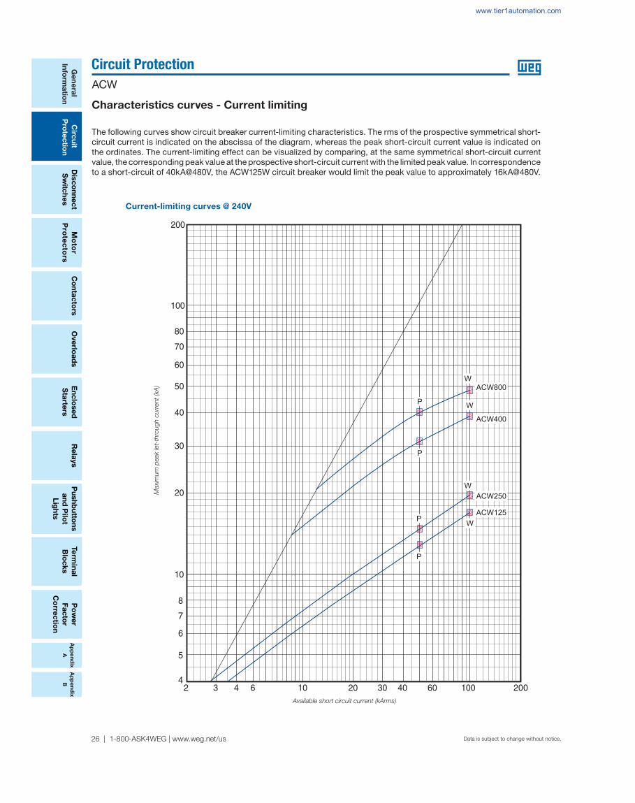
Current-limiting curves @ 240V
Characteristics curves - Current limiting
The following curves show circuit breaker current-limiting characteristics. The rms of the prospective symmetrical short-circuit current is indicated on the abscissa of the diagram, whereas the peak short-circuit current value is indicated on the ordinates. The current-limiting effect can be visualized by comparing, at the same symmetrical short-circuit current value, the corresponding peak value at the prospective short-circuit current with the limited peak value. In correspondence to a short-circuit of 40kA@480V, the ACW125W circuit breaker would limit the peak value to approximately 16kA@480V.
ACW800
ACW400
W
WP
P
W
P
P
W
ACW250
ACW125
Available short circuit current (kArms)
Maxim
um
peak let-
thro
ugh c
urr
ent
(kA
)
www.tier1automation.com

Ap
pe
nd
ix
A
Ap
pe
nd
ix
B
Po
we
r
Fa
cto
r
Co
rre
cti
on
Te
rmin
al
Blo
ck
s
Pu
sh
bu
tto
ns
an
d P
ilo
t
Lig
hts
Ove
rlo
ad
sC
on
tac
tors
Mo
tor
Pro
tec
tors
Dis
co
nn
ec
t
Sw
itc
he
s
Re
lays
Cir
cu
it
Pro
tec
tio
n
Ge
ne
ral
Info
rma
tio
n
En
clo
se
d
Sta
rte
rs
WEG Automation - Products and Solutions | 27Data is subject to change without notice.
Circuit Protection
ACW
Ap
pe
nd
ix
A
Ap
pe
nd
ix
B
Current-limiting curves @ 480V
Characteristics curves - Current limiting
Available short circuit current (kArms)
Maxim
um
peak let-
thro
ugh c
urr
ent
(kA
)
P
W
P
W
W
WP
P
ACW800
ACW400
ACW250
ACW125
www.tier1automation.com

Ap
pe
nd
ix
A
Ap
pe
nd
ix
B
Ge
ne
ral
Info
rma
tion
Circ
uit
Pro
tec
tion
Dis
co
nn
ec
t
Sw
itch
es
Mo
tor
Pro
tec
tors
Ove
rloa
ds
Re
lays
Pu
sh
bu
tton
s
an
d P
ilot
Lig
hts
Te
rmin
al
Blo
ck
s
Co
nta
cto
rsP
ow
er
Fa
cto
r
Co
rrec
tion
En
clo
se
d
Sta
rters
Data is subject to change without notice.
Circuit Protection
ACW
28 | 1-800-ASK4WEG | www.weg.net/us
Current-limiting curves @ 600V
Characteristics curves - Current limiting
ACW800
W
P
ACW400
W
P
W
ACW250
P
W
P
ACW125
Available short circuit current (kArms)
Maxim
um
peak let-
thro
ugh c
urr
ent
(kA
)
www.tier1automation.com

Ap
pe
nd
ix
A
Ap
pe
nd
ix
B
Po
we
r
Fa
cto
r
Co
rre
cti
on
Te
rmin
al
Blo
ck
s
Pu
sh
bu
tto
ns
an
d P
ilo
t
Lig
hts
Ove
rlo
ad
sC
on
tac
tors
Mo
tor
Pro
tec
tors
Dis
co
nn
ec
t
Sw
itc
he
s
Re
lays
Cir
cu
it
Pro
tec
tio
n
Ge
ne
ral
Info
rma
tio
n
En
clo
se
d
Sta
rte
rs
WEG Automation - Products and Solutions | 29Data is subject to change without notice.
Circuit Protection
ACW
Ap
pe
nd
ix
A
Ap
pe
nd
ix
B
Let-through energy curves @ 240V
Characteristics curves - Let-through energy
Available short circuit current (kArms)
The prospective symmetrical short-circuit current is indicated on the abscissa of the diagram, whereas the ordinates show the specifi c let through energy values expressed in A2s. In correspondence to a short-circuit of 65kA@480V, the ACW125W circuit breaker lets through a value of I2t approximately to 400kA2s.
Maxim
um
let-
thro
ugh l²t
(A
²s)
W
ACW800
ACW400
W
W
W
P
P
P
P
ACW250
ACW125
www.tier1automation.com

Ap
pe
nd
ix
A
Ap
pe
nd
ix
B
Ge
ne
ral
Info
rma
tion
Circ
uit
Pro
tec
tion
Dis
co
nn
ec
t
Sw
itch
es
Mo
tor
Pro
tec
tors
Ove
rloa
ds
Re
lays
Pu
sh
bu
tton
s
an
d P
ilot
Lig
hts
Te
rmin
al
Blo
ck
s
Co
nta
cto
rsP
ow
er
Fa
cto
r
Co
rrec
tion
En
clo
se
d
Sta
rters
Data is subject to change without notice.
Circuit Protection
ACW
30 | 1-800-ASK4WEG | www.weg.net/us
Let-through energy curves @ 480V
Characteristics curves - Let-through energy
Maxim
um
let-
thro
ugh l²t
(A
²s)
ACW800
ACW400
ACW250
ACW125
W
W
P
P
P
P
W
W
Available short circuit current (kArms)
www.tier1automation.com

Ap
pe
nd
ix
A
Ap
pe
nd
ix
B
Po
we
r
Fa
cto
r
Co
rre
cti
on
Te
rmin
al
Blo
ck
s
Pu
sh
bu
tto
ns
an
d P
ilo
t
Lig
hts
Ove
rlo
ad
sC
on
tac
tors
Mo
tor
Pro
tec
tors
Dis
co
nn
ec
t
Sw
itc
he
s
Re
lays
Cir
cu
it
Pro
tec
tio
n
Ge
ne
ral
Info
rma
tio
n
En
clo
se
d
Sta
rte
rs
WEG Automation - Products and Solutions | 31Data is subject to change without notice.
Circuit Protection
ACW
Ap
pe
nd
ix
A
Ap
pe
nd
ix
B
Let-through energy curves @ 600V
Characteristics curves - Let-through energy
ACW800
ACW400
ACW250
ACW125
W
P
P
W
P
P
W
W
Available short circuit current (kArms)
Maxim
um
peak let-
thro
ug
h c
urr
ent
(kA
)
www.tier1automation.com

Ap
pe
nd
ix
A
Ap
pe
nd
ix
B
Ge
ne
ral
Info
rma
tion
Circ
uit
Pro
tec
tion
Dis
co
nn
ec
t
Sw
itch
es
Mo
tor
Pro
tec
tors
Ove
rloa
ds
Re
lays
Pu
sh
bu
tton
s
an
d P
ilot
Lig
hts
Te
rmin
al
Blo
ck
s
Co
nta
cto
rsP
ow
er
Fa
cto
r
Co
rrec
tion
En
clo
se
d
Sta
rters
Data is subject to change without notice.
Circuit Protection
ACW
32 | 1-800-ASK4WEG | www.weg.net/us
ACW125
Dimensions - inch (mm)
ACW250
Drillingtemplate
Drillingtemplate
Front viewcut-out
Front viewcut-out
www.tier1automation.com

Ap
pe
nd
ix
A
Ap
pe
nd
ix
B
Po
we
r
Fa
cto
r
Co
rre
cti
on
Te
rmin
al
Blo
ck
s
Pu
sh
bu
tto
ns
an
d P
ilo
t
Lig
hts
Ove
rlo
ad
sC
on
tac
tors
Mo
tor
Pro
tec
tors
Dis
co
nn
ec
t
Sw
itc
he
s
Re
lays
Cir
cu
it
Pro
tec
tio
n
Ge
ne
ral
Info
rma
tio
n
En
clo
se
d
Sta
rte
rs
WEG Automation - Products and Solutions | 33Data is subject to change without notice.
Circuit Protection
ACW
Ap
pe
nd
ix
A
Ap
pe
nd
ix
B
ACW400
ACW800
Dimensions - inch (mm)
Drillingtemplate
Drillingtemplate
Front viewcut-out
Front viewcut-out
www.tier1automation.com

Ap
pe
nd
ix
A
Ap
pe
nd
ix
B
Ge
ne
ral
Info
rma
tion
Circ
uit
Pro
tec
tion
Dis
co
nn
ec
t
Sw
itch
es
Mo
tor
Pro
tec
tors
Ove
rloa
ds
Re
lays
Pu
sh
bu
tton
s
an
d P
ilot
Lig
hts
Te
rmin
al
Blo
ck
s
Co
nta
cto
rsP
ow
er
Fa
cto
r
Co
rrec
tion
En
clo
se
d
Sta
rters
Data is subject to change without notice.
Circuit Protection
ACW
34 | 1-800-ASK4WEG | www.weg.net/us
14.5 (368.3)
14.5(368.3) - 12” shaft18.5(470) - 16” shaft26.5(673.1) - 24” shaft
Panel drilling Installation Diagram
Dimensions - inch (mm)
Extended rotary handle - ACW125
www.tier1automation.com
Ap
pe
nd
ix
A
Ap
pe
nd
ix
B
Po
we
r
Fa
cto
r
Co
rre
cti
on
Te
rmin
al
Blo
ck
s
Pu
sh
bu
tto
ns
an
d P
ilo
t
Lig
hts
Ove
rlo
ad
sC
on
tac
tors
Mo
tor
Pro
tec
tors
Dis
co
nn
ec
t
Sw
itc
he
s
Re
lays
Cir
cu
it
Pro
tec
tio
n
Ge
ne
ral
Info
rma
tio
n
En
clo
se
d
Sta
rte
rs
WEG Automation - Products and Solutions | 35Data is subject to change without notice.
Circuit Protection
ACW
Ap
pe
nd
ix
A
Ap
pe
nd
ix
B
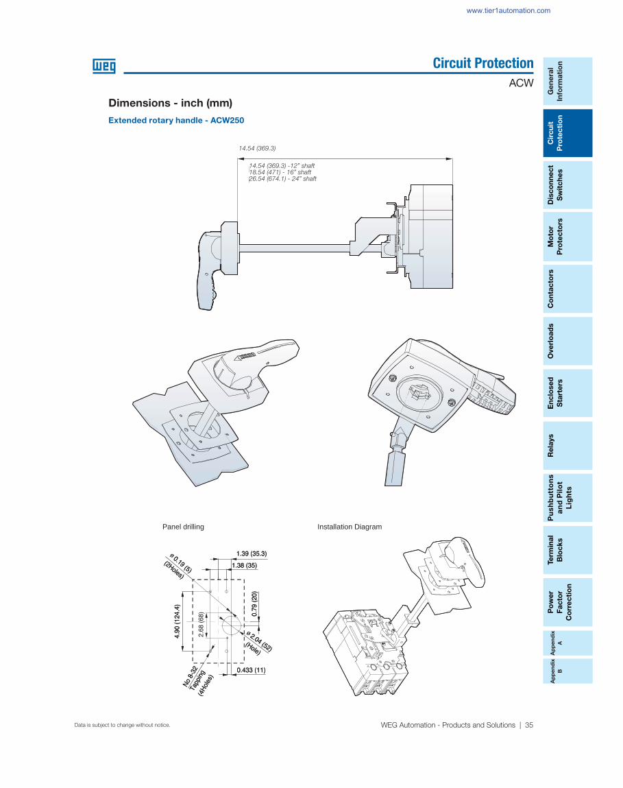
Panel drilling Installation Diagram
Dimensions - inch (mm)
Extended rotary handle - ACW250
14.54 (369.3)
14.54 (369.3) -12” shaft18.54 (471) - 16” shaft26.54 (674.1) - 24” shaft
www.tier1automation.com

Ap
pe
nd
ix
A
Ap
pe
nd
ix
B
Ge
ne
ral
Info
rma
tion
Circ
uit
Pro
tec
tion
Dis
co
nn
ec
t
Sw
itch
es
Mo
tor
Pro
tec
tors
Ove
rloa
ds
Re
lays
Pu
sh
bu
tton
s
an
d P
ilot
Lig
hts
Te
rmin
al
Blo
ck
s
Co
nta
cto
rsP
ow
er
Fa
cto
r
Co
rrec
tion
En
clo
se
d
Sta
rters
Data is subject to change without notice.
Circuit Protection
ACW
36 | 1-800-ASK4WEG | www.weg.net/us
15.93 (404.6) -12” shaft19.93 (506) - 16” shaft27.93 (709.4) -24” shaft
Panel drilling Installation Diagram
Dimensions - inch (mm)
Extended rotary handle - ACW400
www.tier1automation.com

Ap
pe
nd
ix
A
Ap
pe
nd
ix
B
Po
we
r
Fa
cto
r
Co
rre
cti
on
Te
rmin
al
Blo
ck
s
Pu
sh
bu
tto
ns
an
d P
ilo
t
Lig
hts
Ove
rlo
ad
sC
on
tac
tors
Mo
tor
Pro
tec
tors
Dis
co
nn
ec
t
Sw
itc
he
s
Re
lays
Cir
cu
it
Pro
tec
tio
n
Ge
ne
ral
Info
rma
tio
n
En
clo
se
d
Sta
rte
rs
WEG Automation - Products and Solutions | 37Data is subject to change without notice.
Circuit Protection
ACW
Ap
pe
nd
ix
A
Ap
pe
nd
ix
B
Panel drilling Installation Diagram
Dimensions - inch (mm)
Extended rotary handle - ACW800
17.42 (442.5) - 12” shaft21.42 (541.2) - 16” shaft29.42 (747.32) - 24” shaft
www.tier1automation.com
Ap
pe
nd
ix
A
Ap
pe
nd
ix
B
Ge
ne
ral
Info
rma
tion
Circ
uit
Pro
tec
tion
Dis
co
nn
ec
t
Sw
itch
es
Mo
tor
Pro
tec
tors
Ove
rloa
ds
Re
lays
Pu
sh
bu
tton
s
an
d P
ilot
Lig
hts
Te
rmin
al
Blo
ck
s
Co
nta
cto
rsP
ow
er
Fa
cto
r
Co
rrec
tion
En
clo
se
d
Sta
rters
Data is subject to change without notice.
Circuit Protection
ACW
38 | 1-800-ASK4WEG | www.weg.net/us
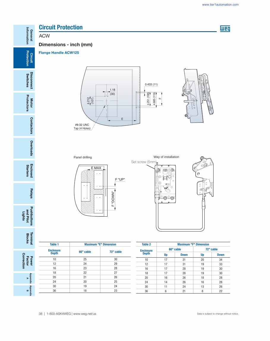
Dimensions - inch (mm)
Flange Handle ACW125
Panel drilling Way of installation
Table 1 Maximum "E" Dimension
Enclosure Depth 60” cable 72” cable
10 25 3012 24 2916 23 2818 22 2720 21 2624 20 2530 19 2436 18 23
Table 2 Maximum "F" Dimension
Enclosure Depth
60” cable 72” cable
Up Down Up Down
10 17 31 20 3412 17 31 19 3316 17 28 19 3018 17 28 19 3020 16 26 18 2824 14 26 16 2830 11 24 13 2636 6 21 8 22
Set screw (5mm)
www.tier1automation.com

Ap
pe
nd
ix
A
Ap
pe
nd
ix
B
Po
we
r
Fa
cto
r
Co
rre
cti
on
Te
rmin
al
Blo
ck
s
Pu
sh
bu
tto
ns
an
d P
ilo
t
Lig
hts
Ove
rlo
ad
sC
on
tac
tors
Mo
tor
Pro
tec
tors
Dis
co
nn
ec
t
Sw
itc
he
s
Re
lays
Cir
cu
it
Pro
tec
tio
n
Ge
ne
ral
Info
rma
tio
n
En
clo
se
d
Sta
rte
rs
WEG Automation - Products and Solutions | 39Data is subject to change without notice.
Circuit Protection
ACW
Ap
pe
nd
ix
A
Ap
pe
nd
ix
B
Dimensions - inch (mm)
Flange Handle ACW250
Panel drilling Installation Diagram
Table 1 Maximum "E" Dimension
Enclosure Depth 60” cable 72” cable
10 25 3012 24 2916 23 2818 22 2720 21 2624 20 2530 19 2436 18 23
Table 2 Maximum "F" Dimension
Enclosure Depth
60” cable 72” cable
Up Down Up Down
10 17 31 20 3412 17 31 19 3316 17 28 19 3018 17 28 19 3020 16 26 18 2824 14 26 16 2830 11 24 13 2636 6 21 8 22
Set screw (5mm)
www.tier1automation.com

Ap
pe
nd
ix
A
Ap
pe
nd
ix
B
Ge
ne
ral
Info
rma
tion
Circ
uit
Pro
tec
tion
Dis
co
nn
ec
t
Sw
itch
es
Mo
tor
Pro
tec
tors
Ove
rloa
ds
Re
lays
Pu
sh
bu
tton
s
an
d P
ilot
Lig
hts
Te
rmin
al
Blo
ck
s
Co
nta
cto
rsP
ow
er
Fa
cto
r
Co
rrec
tion
En
clo
se
d
Sta
rters
Data is subject to change without notice.
Circuit Protection
ACW
40 | 1-800-ASK4WEG | www.weg.net/us
Dimensions - inch (mm)
Flange Handle ACW400
Panel drilling Installation Diagram
Table 1 Maximum "E" Dimension
Enclosure Depth 60” cable 72” cable
10 25 3012 24 2916 23 2818 22 2720 21 2624 20 2530 19 2436 18 23
Table 2 Maximum "F" Dimension
Enclosure Depth
60” cable 72” cable
Up Down Up Down
10 17 31 20 34
12 17 31 19 3316 17 28 19 3018 17 28 19 3020 16 26 18 2824 14 26 16 2830 11 24 13 2636 6 21 8 22
Set screw (5mm)
www.tier1automation.com

Ap
pe
nd
ix
A
Ap
pe
nd
ix
B
Po
we
r
Fa
cto
r
Co
rre
cti
on
Te
rmin
al
Blo
ck
s
Pu
sh
bu
tto
ns
an
d P
ilo
t
Lig
hts
Ove
rlo
ad
sC
on
tac
tors
Mo
tor
Pro
tec
tors
Dis
co
nn
ec
t
Sw
itc
he
s
Re
lays
Cir
cu
it
Pro
tec
tio
n
Ge
ne
ral
Info
rma
tio
n
En
clo
se
d
Sta
rte
rs
WEG Automation - Products and Solutions | 41Data is subject to change without notice.
Circuit Protection
ACW
Ap
pe
nd
ix
A
Ap
pe
nd
ix
B
AC
W S
ER
IES
Dimensions - inch (mm)
Flange Handle ACW800
Panel drilling Installation diagram
Table 1 Maximum "E" Dimension
Enclosure Depth 60” cable 72” cable
10 25 3012 24 2916 23 2818 22 2720 21 2624 20 2530 19 2436 18 23
Table 2 Maximum "F" Dimension
Enclosure Depth
60” cable 72” cable
Up Down Up Down
10 17 31 20 3412 17 31 19 3316 17 28 19 3018 17 28 19 3020 16 26 18 2824 14 26 16 2830 11 24 13 2636 6 21 8 22
Set screw (5mm)
www.tier1automation.com

Ap
pe
nd
ix
A
Ap
pe
nd
ix
B
Ge
ne
ral
Info
rma
tion
Circ
uit
Pro
tec
tion
Dis
co
nn
ec
t
Sw
itch
es
Mo
tor
Pro
tec
tors
Ove
rloa
ds
Re
lays
Pu
sh
bu
tton
s
an
d P
ilot
Lig
hts
Te
rmin
al
Blo
ck
s
Co
nta
cto
rsP
ow
er
Fa
cto
r
Co
rrec
tion
En
clo
se
d
Sta
rters
Data is subject to change without notice.
Circuit Protection
ACW
42 | 1-800-ASK4WEG | www.weg.net/us
Dimensions - inch (mm)
Mechanical interlocking device - MIT
Mechanical interlocking device - Mounting dimension for MIT
A (inch) B (inch)
ACW125 3.267 3.385
ACW250 4.015 3.385
ACW400 6.614 4.330
ACW800 7.193 5.314
3 Pole MCCB
C(inch) D(inch) E(inch)
ACW125 4.212 3.543 1.181
ACW250 4.921 4.133 1.377
ACW400 7.874 5.490 1.830
ACW800 10.944 8.267 2.755
www.tier1automation.com