CIRCUIT PROTECTION SOLUTIONS
30
1 CIRCUIT PROTECTION SOLUTIONS TVS Diode Array Port Selection Guide Applying the SPA™ product family to ports ESD Protection for Human Interfaces & Low Speed I/Os ESD Protection for High Speed Data Ports ESD & Lightning Surge Protection for Broadband Ports r110407 April 2011
-
Upload
lillian-osborne -
Category
Documents
-
view
38 -
download
1
description
CIRCUIT PROTECTION SOLUTIONS. TVS Diode Array Port Selection Guide Applying the SPA™ product family to ports ESD Protection for Human Interfaces & Low Speed I/Os ESD Protection for High Speed Data Ports ESD & Lightning Surge Protection for Broadband Ports. r110407 April 2011. - PowerPoint PPT Presentation
Transcript of CIRCUIT PROTECTION SOLUTIONS
1
CIRCUIT
PROTECTION
SOLUTIONS
TVS Diode Array Port Selection GuideApplying the SPA™ product family to ports
ESD Protection for Human Interfaces & Low Speed I/OsESD Protection for High Speed Data PortsESD & Lightning Surge Protection for Broadband Ports
r110407 April 2011
2
How to use the TVS Diode Array Port Selection Guide
• Change to “presentation mode” to activate links
• The selection guide is driven from the next slide
• The basic format is to align the product line and protected ports, by grouping them into three categories
• To see examples of TVS Diode Arrays protecting the specific ports, simply click on the links on the next page
Click here to go to the Selection Guide
Click here to go to the Selection Guide
This guide is meant to provide examples the use of TVS Diode Arrays for the protection of a large number of different ports. The ports represent low-speed, high-speed and ports where the electrical threat is not just ESD, but also lightning surge.
It should be kept in mind that there will typically be multiple solutions available for each port and that they are equally valid. A typical reason to use a different part than the one identified in the slide would be form factor (SOT23 vs. SC70 vs. μDFN).
TVS Diode Array – SPA™ FamilyPort Selection Guide Introduction
3
This guide is meant to provide examples of the application of TVS Diode Arrays in the protection of a wide range of port types. The circuits represent low-speed, high-speed and ports where the electrical threat is not just ESD, but also lightning surge (Broadband applications).
It should be kept in mind that there will typically be multiple, equally-valid solutions available for each port. A typical reason to use a part other than the one identified in the slide could be form factor (SOT23 vs. SC70 vs. μDFN). Another example is that a single USB 2.0 port can use the SP3003-02xTG, but it would be a logical choice to use the SP3003-04xTG for a USB 2.0 connector that includes two USB 2.0 ports (rather than two of the SP3003-02xTG).
The selection guide can be used in two modes:
• Port Selection – in this mode, you need to know which port needs protection. For example, if you are working on a set top box design, and need to find protection solutions for high-speed ports, you can search under HDMI, USB 2.0, eSATA and/or Ethernet.
• Part Number Index – in this mode, you need to know a specific TVS Diode Array part number. For example, if you’ve just learned about the SP3010-04UTG through a promotion or training, you can search under that part number.
TVS Diode Array – SPA™ FamilyPort Selection Guide Introduction
4
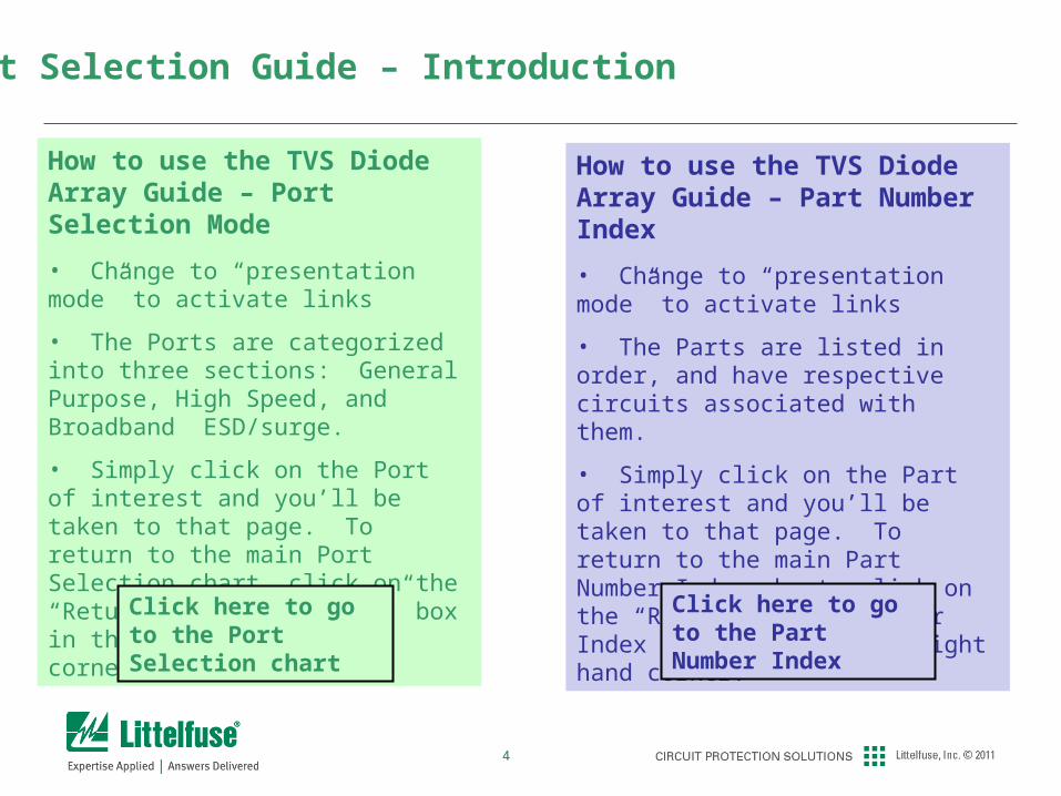
How to use the TVS Diode Array Guide – Port Selection Mode
• Change to “presentation mode” to activate links
• The Ports are categorized into three sections: General Purpose, High Speed, and Broadband ESD/surge.
• Simply click on the Port of interest and you’ll be taken to that page. To return to the main Port Selection chart, click on the “Return to Port Selector” box in the upper right hand corner.
Click here to go to the Port Selection chart
Port Selection Guide – Introduction
How to use the TVS Diode Array Guide – Part Number Index
• Change to “presentation mode” to activate links
• The Parts are listed in order, and have respective circuits associated with them.
• Simply click on the Part of interest and you’ll be taken to that page. To return to the main Part Number Index chart, click on the “Return to Part Number Index” box in the upper right hand corner.
Click here to go to the Part Number Index
5
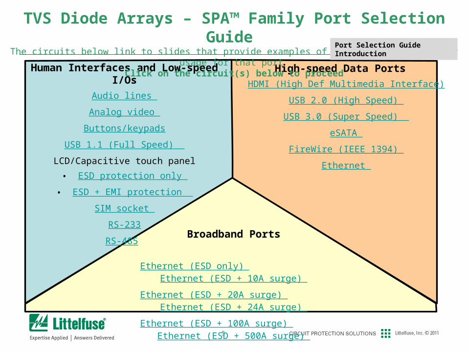
Human Interfaces and Low-speed I/Os
Audio lines
Analog video
Buttons/keypads
USB 1.1 (Full Speed)
LCD/Capacitive touch panel
• ESD protection only
• ESD + EMI protection
SIM socket
RS-233
RS-485
High-speed Data Ports
HDMI (High Def Multimedia Interface)
USB 2.0 (High Speed)
USB 3.0 (Super Speed)
eSATA
FireWire (IEEE 1394)
Ethernet
Broadband Ports
Ethernet (ESD only) Ethernet (ESD + 10A surge)
Ethernet (ESD + 20A surge) Ethernet (ESD + 24A surge)
Ethernet (ESD + 100A surge) Ethernet (ESD + 500A surge)
TVS Diode Arrays – SPA™ Family Port Selection Guide The circuits below link to slides that provide examples of typical TVS Diode Array usage for that port
Click on the circuit(s) below to proceed Port Selection Guide Introduction
6
Human Interfaces and Low Speed I/Os
7
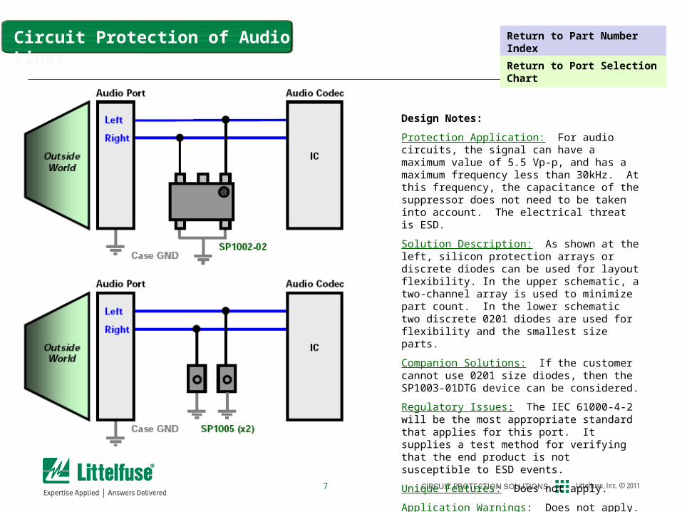
Circuit Protection of Audio Lines
Design Notes:
Protection Application: For audio circuits, the signal can have a maximum value of 5.5 Vp-p, and has a maximum frequency less than 30kHz. At this frequency, the capacitance of the suppressor does not need to be taken into account. The electrical threat is ESD.
Solution Description: As shown at the left, silicon protection arrays or discrete diodes can be used for layout flexibility. In the upper schematic, a two-channel array is used to minimize part count. In the lower schematic two discrete 0201 diodes are used for flexibility and the smallest size parts.
Companion Solutions: If the customer cannot use 0201 size diodes, then the SP1003-01DTG device can be considered.
Regulatory Issues: The IEC 61000-4-2 will be the most appropriate standard that applies for this port. It supplies a test method for verifying that the end product is not susceptible to ESD events.
Unique Features: Does not apply.
Application Warnings: Does not apply.
Return to Part Number Index
Return to Port Selection Chart
8
Design Notes:
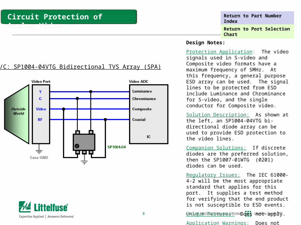
Protection Application: The video signals used in S-video and Composite video formats have a maximum frequency of 5MHz. At this frequency, a general purpose ESD array can be used. The signal lines to be protected from ESD include Luminance and Chrominance for S-video, and the single conductor for Composite video.
Solution Description: As shown at the left, an SP1004-04VTG bi-directional diode array can be used to provide ESD protection to the video lines.
Companion Solutions: If discrete diodes are the preferred solution, then the SP1007-01WTG (0201) diodes can be used.
Regulatory Issues: The IEC 61000-4-2 will be the most appropriate standard that applies for this port. It supplies a test method for verifying that the end product is not susceptible to ESD events.
Unique Features: Does not apply.
Application Warnings: Does not apply.
L/C: SP1004-04VTG Bidirectional TVS Array (SPA)
Circuit Protection of Analog Video Return to Part Number Index
Return to Port Selection Chart
9
Circuit Protection of Keypads/Buttons
Design Notes:
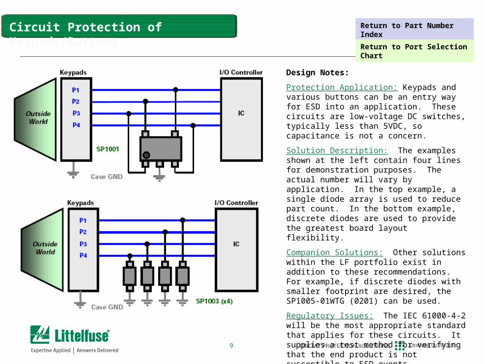
Protection Application: Keypads and various buttons can be an entry way for ESD into an application. These circuits are low-voltage DC switches, typically less than 5VDC, so capacitance is not a concern.
Solution Description: The examples shown at the left contain four lines for demonstration purposes. The actual number will vary by application. In the top example, a single diode array is used to reduce part count. In the bottom example, discrete diodes are used to provide the greatest board layout flexibility.
Companion Solutions: Other solutions within the LF portfolio exist in addition to these recommendations. For example, if discrete diodes with smaller footprint are desired, the SP1005-01WTG (0201) can be used.
Regulatory Issues: The IEC 61000-4-2 will be the most appropriate standard that applies for these circuits. It supplies a test method for verifying that the end product is not susceptible to ESD events.
Unique Features: Does not apply.
Application Warnings: Does not apply.
Return to Part Number Index
Return to Port Selection Chart
10
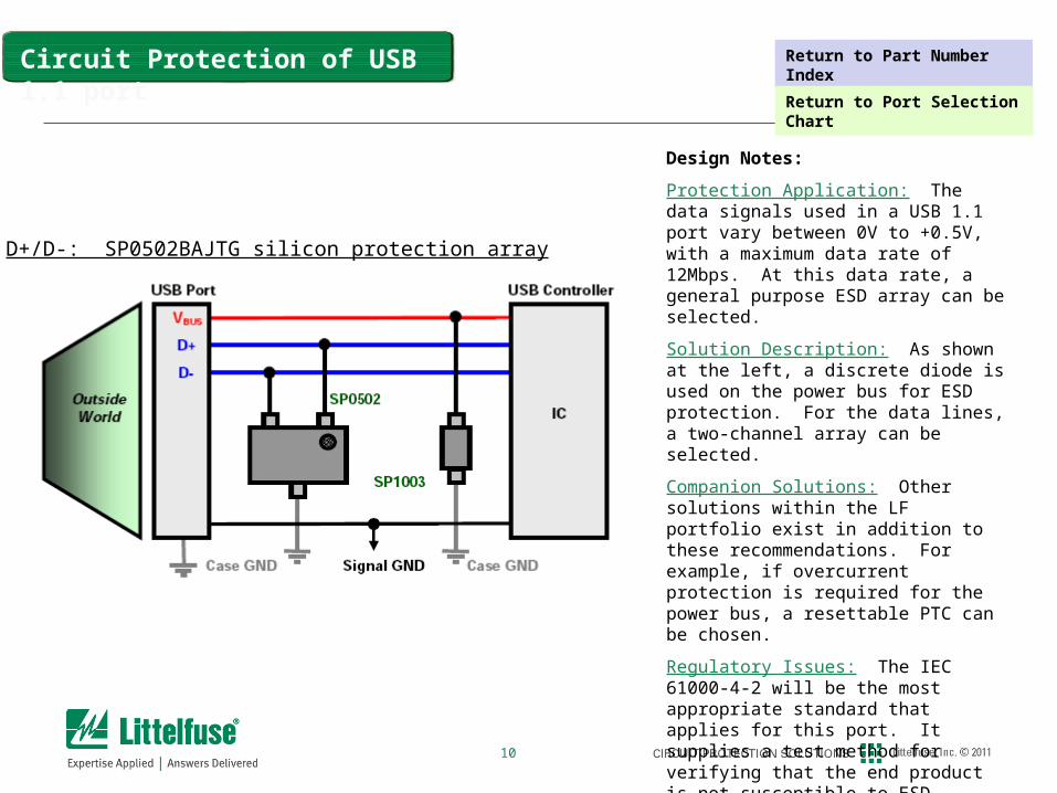
D+/D-: SP0502BAJTG silicon protection array
Design Notes:
Protection Application: The data signals used in a USB 1.1 port vary between 0V to +0.5V, with a maximum data rate of 12Mbps. At this data rate, a general purpose ESD array can be selected.
Solution Description: As shown at the left, a discrete diode is used on the power bus for ESD protection. For the data lines, a two-channel array can be selected.
Companion Solutions: Other solutions within the LF portfolio exist in addition to these recommendations. For example, if overcurrent protection is required for the power bus, a resettable PTC can be chosen.
Regulatory Issues: The IEC 61000-4-2 will be the most appropriate standard that applies for this port. It supplies a test method for verifying that the end product is not susceptible to ESD events.
Unique Features: Does not apply.
Application Warnings: Does not apply.
Circuit Protection of USB 1.1 port Return to Part Number Index
Return to Port Selection Chart
11
Design Notes:
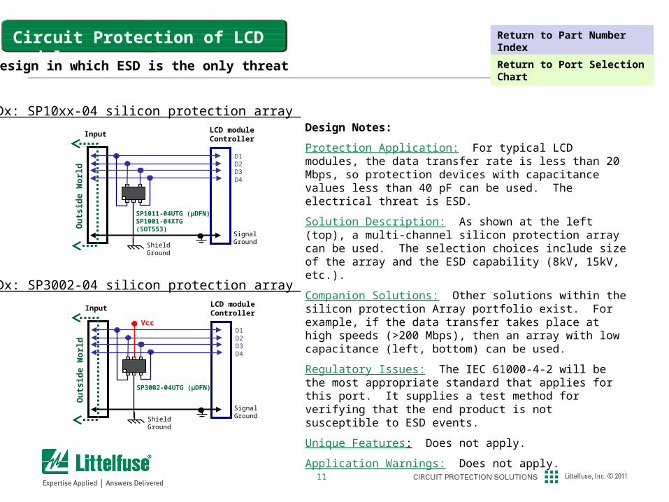
Protection Application: For typical LCD modules, the data transfer rate is less than 20 Mbps, so protection devices with capacitance values less than 40 pF can be used. The electrical threat is ESD.
Solution Description: As shown at the left (top), a multi-channel silicon protection array can be used. The selection choices include size of the array and the ESD capability (8kV, 15kV, etc.).
Companion Solutions: Other solutions within the silicon protection Array portfolio exist. For example, if the data transfer takes place at high speeds (>200 Mbps), then an array with low capacitance (left, bottom) can be used.
Regulatory Issues: The IEC 61000-4-2 will be the most appropriate standard that applies for this port. It supplies a test method for verifying that the end product is not susceptible to ESD events.
Unique Features: Does not apply.
Application Warnings: Does not apply.
Circuit Protection of LCD module
Dx: SP10xx-04 silicon protection array
Signal Ground
Ou
tsid
e W
orl
d
SP1011-04UTG (µDFN)SP1001-04XTG (SOT553)
ShieldGround
LCD moduleController
D1D2D3D4
Input
Dx: SP3002-04 silicon protection array
Signal Ground
Ou
tsid
e W
orl
d
SP3002-04UTG (μDFN)
ShieldGround
LCD moduleController
D1D2D3D4
Input
Vcc
Design in which ESD is the only threat
Return to Part Number Index
Return to Port Selection Chart
12
Design Notes:
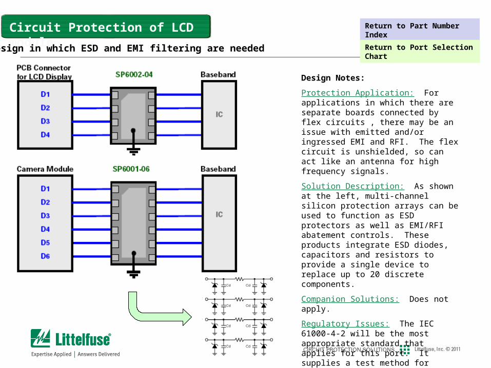
Protection Application: For applications in which there are separate boards connected by flex circuits , there may be an issue with emitted and/or ingressed EMI and RFI. The flex circuit is unshielded, so can act like an antenna for high frequency signals.
Solution Description: As shown at the left, multi-channel silicon protection arrays can be used to function as ESD protectors as well as EMI/RFI abatement controls. These products integrate ESD diodes, capacitors and resistors to provide a single device to replace up to 20 discrete components.
Companion Solutions: Does not apply.
Regulatory Issues: The IEC 61000-4-2 will be the most appropriate standard that applies for this port. It supplies a test method for verifying that the end product is not susceptible to ESD events.
Unique Features: Does not apply.
Application Warnings: Does not apply.
Circuit Protection of LCD module
Design in which ESD and EMI filtering are needed
Return to Part Number Index
Return to Port Selection Chart
13
Design Notes:
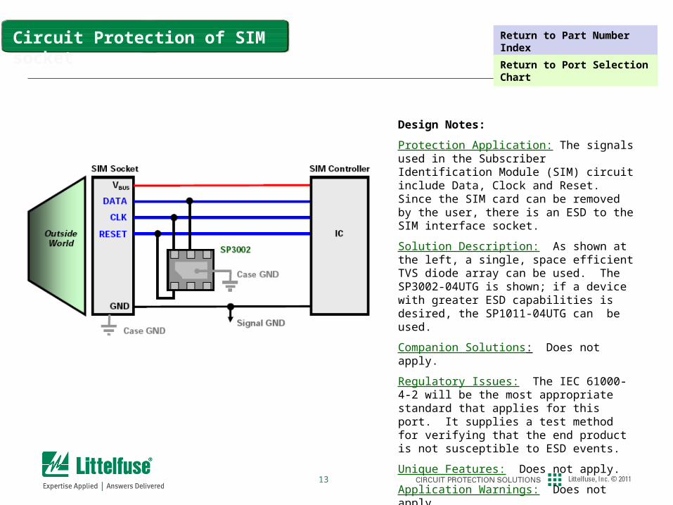
Protection Application: The signals used in the Subscriber Identification Module (SIM) circuit include Data, Clock and Reset. Since the SIM card can be removed by the user, there is an ESD to the SIM interface socket.
Solution Description: As shown at the left, a single, space efficient TVS diode array can be used. The SP3002-04UTG is shown; if a device with greater ESD capabilities is desired, the SP1011-04UTG can be used.
Companion Solutions: Does not apply.
Regulatory Issues: The IEC 61000-4-2 will be the most appropriate standard that applies for this port. It supplies a test method for verifying that the end product is not susceptible to ESD events.
Unique Features: Does not apply.
Application Warnings: Does not apply.
Circuit Protection of SIM socket Return to Part Number Index
Return to Port Selection Chart
14
Design Notes:
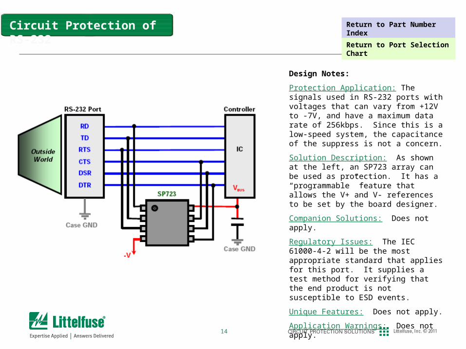
Protection Application: The signals used in RS-232 ports with voltages that can vary from +12V to -7V, and have a maximum data rate of 256kbps. Since this is a low-speed system, the capacitance of the suppress is not a concern.
Solution Description: As shown at the left, an SP723 array can be used as protection. It has a “programmable” feature that allows the V+ and V- references to be set by the board designer.
Companion Solutions: Does not apply.
Regulatory Issues: The IEC 61000-4-2 will be the most appropriate standard that applies for this port. It supplies a test method for verifying that the end product is not susceptible to ESD events.
Unique Features: Does not apply.
Application Warnings: Does not apply.
Circuit Protection of RS-232 Return to Part Number Index
Return to Port Selection Chart
15
Design Notes:
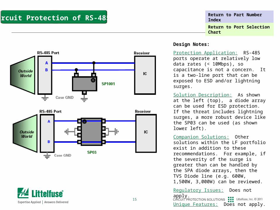
Protection Application: RS-485 ports operate at relatively low data rates (< 10Mbps), so capacitance is not a concern. It is a two-line port that can be exposed to ESD and/or lightning surges.
Solution Description: As shown at the left (top), a diode array can be used for ESD protection. If the threat includes lightning surges, a more robust device like the SP03 can be used (as shown lower left).
Companion Solutions: Other solutions within the LF portfolio exist in addition to these recommendations. For example, if the severity of the surge is greater than can be handled by the SPA diode arrays, then the TVS Diode line (e.g. 600W, 1,500W, 3,000W) can be reviewed.
Regulatory Issues: Does not apply.
Unique Features: Does not apply.
Application Warnings: Does not apply.
Circuit Protection of RS-485 Return to Part Number Index
Return to Port Selection Chart
16
High-speed Data Ports
17
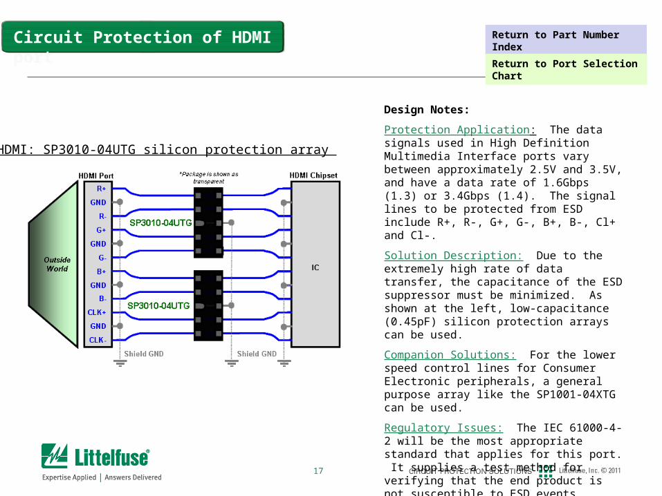
Circuit Protection of HDMI port
Design Notes:
Protection Application: The data signals used in High Definition Multimedia Interface ports vary between approximately 2.5V and 3.5V, and have a data rate of 1.6Gbps (1.3) or 3.4Gbps (1.4). The signal lines to be protected from ESD include R+, R-, G+, G-, B+, B-, Cl+ and Cl-.
Solution Description: Due to the extremely high rate of data transfer, the capacitance of the ESD suppressor must be minimized. As shown at the left, low-capacitance (0.45pF) silicon protection arrays can be used.
Companion Solutions: For the lower speed control lines for Consumer Electronic peripherals, a general purpose array like the SP1001-04XTG can be used.
Regulatory Issues: The IEC 61000-4-2 will be the most appropriate standard that applies for this port. It supplies a test method for verifying that the end product is not susceptible to ESD events.
Unique Features: Does not apply.
Application Warnings: Does not apply.
HDMI: SP3010-04UTG silicon protection array
Return to Part Number Index
Return to Port Selection Chart
18
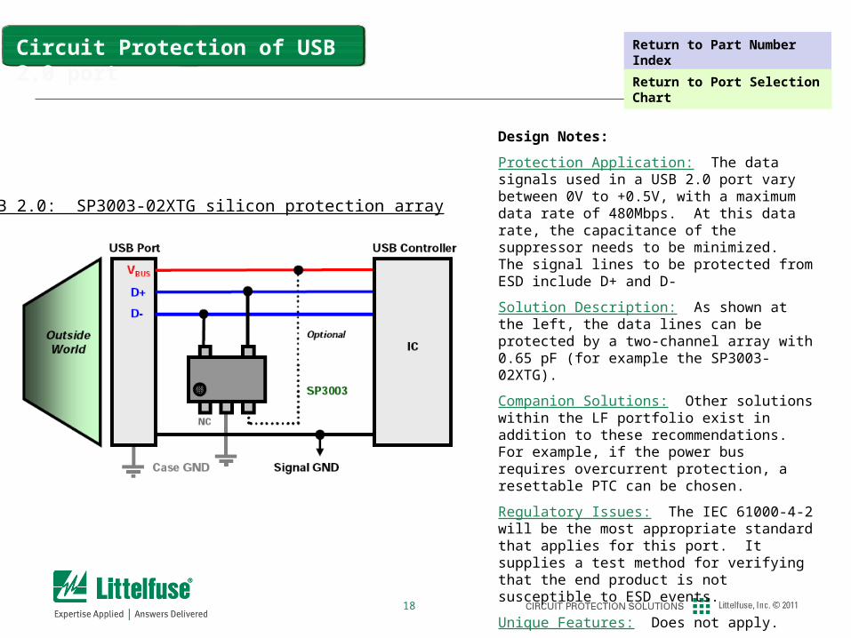
USB 2.0: SP3003-02XTG silicon protection array
Design Notes:
Protection Application: The data signals used in a USB 2.0 port vary between 0V to +0.5V, with a maximum data rate of 480Mbps. At this data rate, the capacitance of the suppressor needs to be minimized. The signal lines to be protected from ESD include D+ and D-
Solution Description: As shown at the left, the data lines can be protected by a two-channel array with 0.65 pF (for example the SP3003-02XTG).
Companion Solutions: Other solutions within the LF portfolio exist in addition to these recommendations. For example, if the power bus requires overcurrent protection, a resettable PTC can be chosen.
Regulatory Issues: The IEC 61000-4-2 will be the most appropriate standard that applies for this port. It supplies a test method for verifying that the end product is not susceptible to ESD events.
Unique Features: Does not apply.
Application Warnings: Does not apply.
Circuit Protection of USB 2.0 port Return to Part Number Index
Return to Port Selection Chart
19
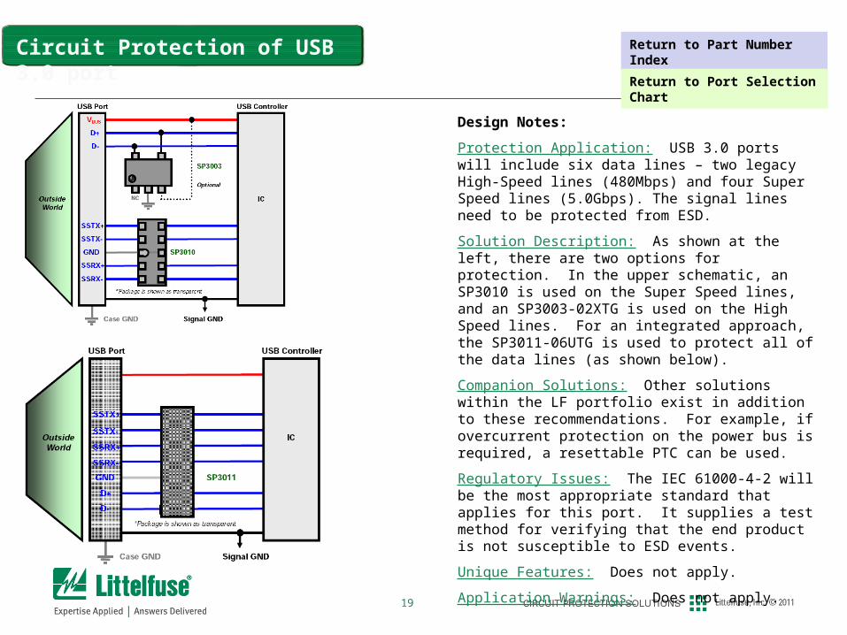
Design Notes:
Protection Application: USB 3.0 ports will include six data lines – two legacy High-Speed lines (480Mbps) and four Super Speed lines (5.0Gbps). The signal lines need to be protected from ESD.
Solution Description: As shown at the left, there are two options for protection. In the upper schematic, an SP3010 is used on the Super Speed lines, and an SP3003-02XTG is used on the High Speed lines. For an integrated approach, the SP3011-06UTG is used to protect all of the data lines (as shown below).
Companion Solutions: Other solutions within the LF portfolio exist in addition to these recommendations. For example, if overcurrent protection on the power bus is required, a resettable PTC can be used.
Regulatory Issues: The IEC 61000-4-2 will be the most appropriate standard that applies for this port. It supplies a test method for verifying that the end product is not susceptible to ESD events.
Unique Features: Does not apply.
Application Warnings: Does not apply.
Circuit Protection of USB 3.0 port Return to Part Number Index
Return to Port Selection Chart
20
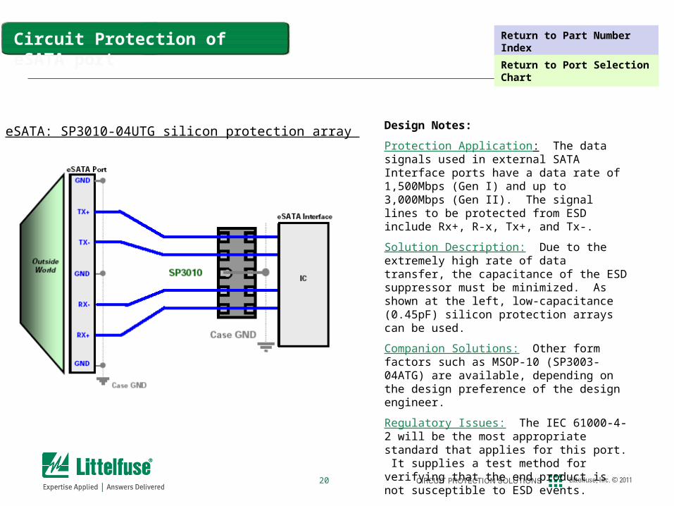
Circuit Protection of eSATA port
Design Notes:
Protection Application: The data signals used in external SATA Interface ports have a data rate of 1,500Mbps (Gen I) and up to 3,000Mbps (Gen II). The signal lines to be protected from ESD include Rx+, R-x, Tx+, and Tx-.
Solution Description: Due to the extremely high rate of data transfer, the capacitance of the ESD suppressor must be minimized. As shown at the left, low-capacitance (0.45pF) silicon protection arrays can be used.
Companion Solutions: Other form factors such as MSOP-10 (SP3003-04ATG) are available, depending on the design preference of the design engineer.
Regulatory Issues: The IEC 61000-4-2 will be the most appropriate standard that applies for this port. It supplies a test method for verifying that the end product is not susceptible to ESD events.
Unique Features: Does not apply.
Application Warnings: Does not apply.
eSATA: SP3010-04UTG silicon protection array
Return to Part Number Index
Return to Port Selection Chart
21
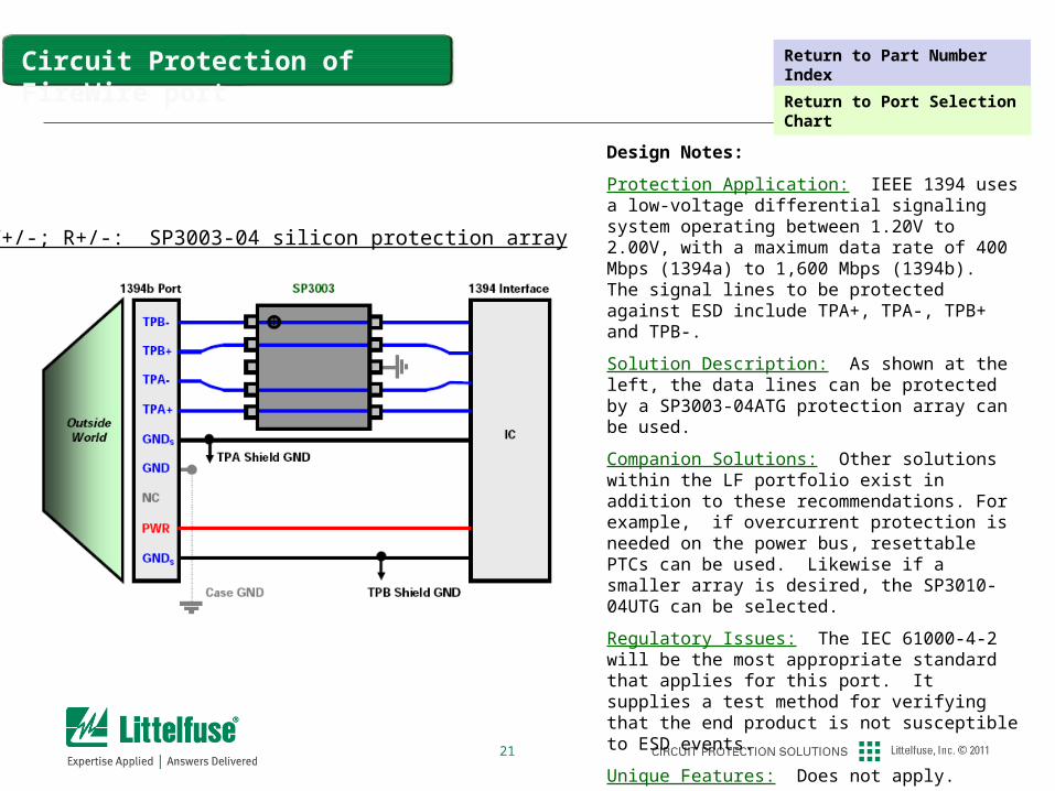
Design Notes:
Protection Application: IEEE 1394 uses a low-voltage differential signaling system operating between 1.20V to 2.00V, with a maximum data rate of 400 Mbps (1394a) to 1,600 Mbps (1394b). The signal lines to be protected against ESD include TPA+, TPA-, TPB+ and TPB-.
Solution Description: As shown at the left, the data lines can be protected by a SP3003-04ATG protection array can be used.
Companion Solutions: Other solutions within the LF portfolio exist in addition to these recommendations. For example, if overcurrent protection is needed on the power bus, resettable PTCs can be used. Likewise if a smaller array is desired, the SP3010-04UTG can be selected.
Regulatory Issues: The IEC 61000-4-2 will be the most appropriate standard that applies for this port. It supplies a test method for verifying that the end product is not susceptible to ESD events.
Unique Features: Does not apply.
Application Warnings: It is recommended that only resettable protection devices like PTCs be used on hot-plug ports like 1394.
T+/-; R+/-: SP3003-04 silicon protection array
Circuit Protection of FireWire port Return to Part Number Index
Return to Port Selection Chart
22
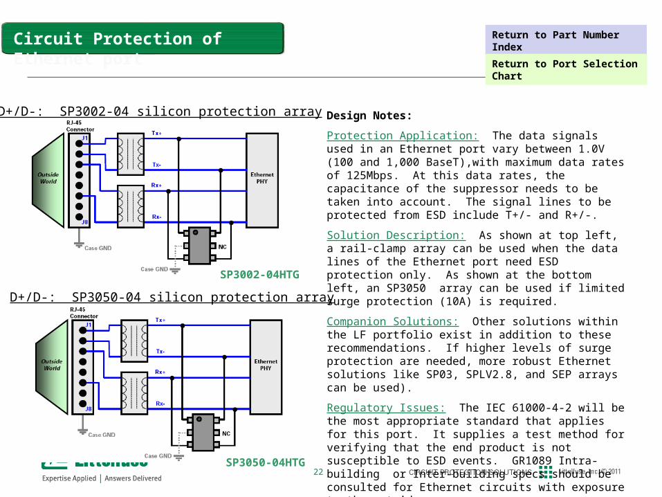
Design Notes:
Protection Application: The data signals used in an Ethernet port vary between 1.0V (100 and 1,000 BaseT),with maximum data rates of 125Mbps. At this data rates, the capacitance of the suppressor needs to be taken into account. The signal lines to be protected from ESD include T+/- and R+/-.
Solution Description: As shown at top left, a rail-clamp array can be used when the data lines of the Ethernet port need ESD protection only. As shown at the bottom left, an SP3050 array can be used if limited surge protection (10A) is required.
Companion Solutions: Other solutions within the LF portfolio exist in addition to these recommendations. If higher levels of surge protection are needed, more robust Ethernet solutions like SP03, SPLV2.8, and SEP arrays can be used).
Regulatory Issues: The IEC 61000-4-2 will be the most appropriate standard that applies for this port. It supplies a test method for verifying that the end product is not susceptible to ESD events. GR1089 Intra-building or Inter-building specs should be consulted for Ethernet circuits with exposure to the outside.
Unique Features: Does not apply.
Application Warnings: Does not apply.
Circuit Protection of Ethernet port
D+/D-: SP3002-04 silicon protection array
SP3002-04HTG
SP3050-04HTG
D+/D-: SP3050-04 silicon protection array
Return to Part Number Index
Return to Port Selection Chart
23
Broadband Ports
24
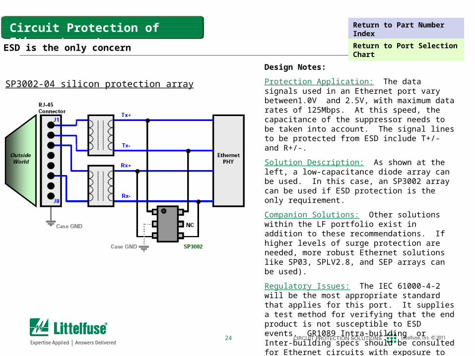
Design Notes:
Protection Application: The data signals used in an Ethernet port vary between1.0V and 2.5V, with maximum data rates of 125Mbps. At this speed, the capacitance of the suppressor needs to be taken into account. The signal lines to be protected from ESD include T+/- and R+/-.
Solution Description: As shown at the left, a low-capacitance diode array can be used. In this case, an SP3002 array can be used if ESD protection is the only requirement.
Companion Solutions: Other solutions within the LF portfolio exist in addition to these recommendations. If higher levels of surge protection are needed, more robust Ethernet solutions like SP03, SPLV2.8, and SEP arrays can be used).
Regulatory Issues: The IEC 61000-4-2 will be the most appropriate standard that applies for this port. It supplies a test method for verifying that the end product is not susceptible to ESD events. GR1089 Intra-building or Inter-building specs should be consulted for Ethernet circuits with exposure to lightning threats.
Unique Features: Does not apply.
Application Warnings: Does not apply.
Circuit Protection of Ethernet port
SP3002-04 silicon protection array
SP3002-04 silicon protection array
ESD is the only concern
Return to Part Number Index
Return to Port Selection Chart
25
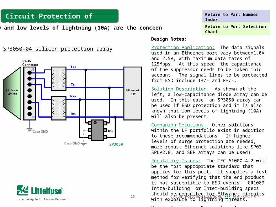
Design Notes:
Protection Application: The data signals used in an Ethernet port vary between1.0V and 2.5V, with maximum data rates of 125Mbps. At this speed, the capacitance of the suppressor needs to be taken into account. The signal lines to be protected from ESD include T+/- and R+/-.
Solution Description: As shown at the left, a low-capacitance diode array can be used. In this case, an SP3050 array can be used if ESD protection and it is also known that low levels of lightning (10A) will also be present.
Companion Solutions: Other solutions within the LF portfolio exist in addition to these recommendations. If higher levels of surge protection are needed, more robust Ethernet solutions like SP03, SPLV2.8, and SEP arrays can be used).
Regulatory Issues: The IEC 61000-4-2 will be the most appropriate standard that applies for this port. It supplies a test method for verifying that the end product is not susceptible to ESD events. GR1089 Intra-building or Inter-building specs should be consulted for Ethernet circuits with exposure to lightning threats.
Unique Features: Does not apply.
Application Warnings: Does not apply.
Circuit Protection of Ethernet port
SP3050-04 silicon protection array
ESD and low levels of lightning (10A) are the concern
SP3050
Return to Part Number Index
Return to Port Selection Chart
26
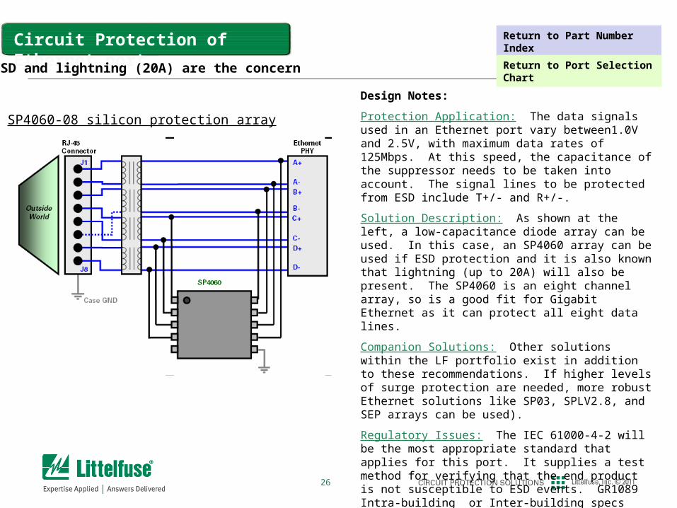
Design Notes:
Protection Application: The data signals used in an Ethernet port vary between1.0V and 2.5V, with maximum data rates of 125Mbps. At this speed, the capacitance of the suppressor needs to be taken into account. The signal lines to be protected from ESD include T+/- and R+/-.
Solution Description: As shown at the left, a low-capacitance diode array can be used. In this case, an SP4060 array can be used if ESD protection and it is also known that lightning (up to 20A) will also be present. The SP4060 is an eight channel array, so is a good fit for Gigabit Ethernet as it can protect all eight data lines.
Companion Solutions: Other solutions within the LF portfolio exist in addition to these recommendations. If higher levels of surge protection are needed, more robust Ethernet solutions like SP03, SPLV2.8, and SEP arrays can be used).
Regulatory Issues: The IEC 61000-4-2 will be the most appropriate standard that applies for this port. It supplies a test method for verifying that the end product is not susceptible to ESD events. GR1089 Intra-building or Inter-building specs should be consulted for Ethernet circuits with exposure to lightning threats.
Unique Features: Does not apply.
Application Warnings: Does not apply.
Circuit Protection of Ethernet port
SP4060-08 silicon protection array
ESD and lightning (20A) are the concern
Return to Part Number Index
Return to Port Selection Chart
27
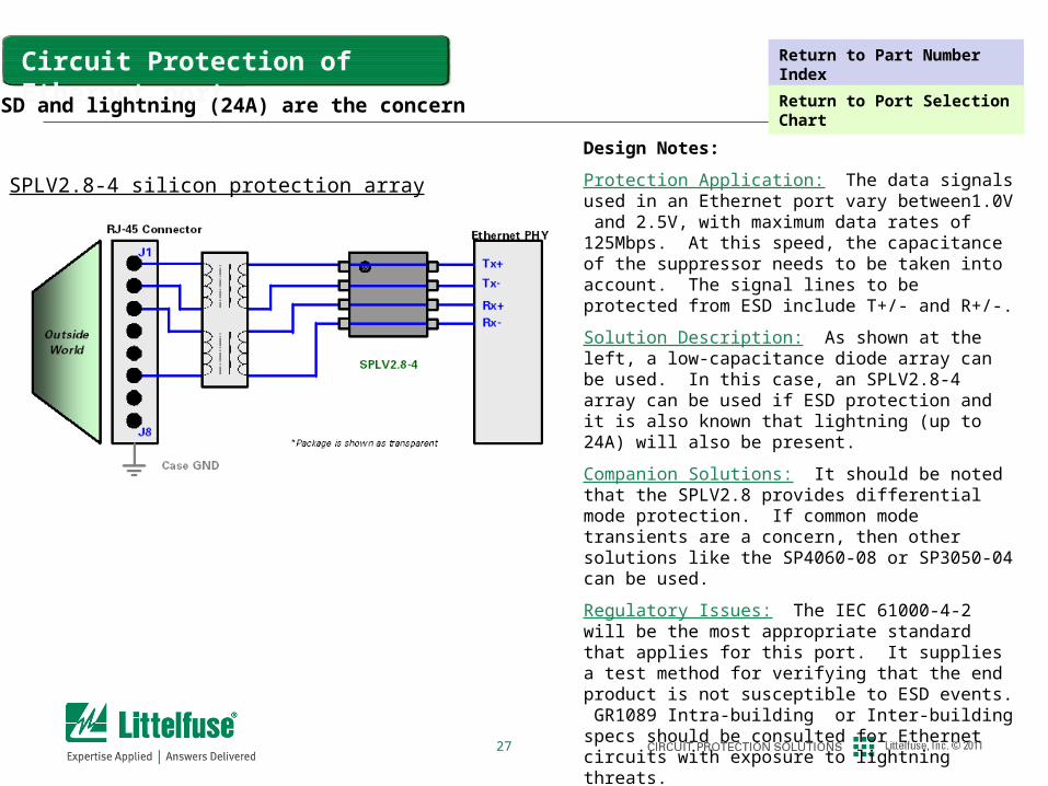
Design Notes:
Protection Application: The data signals used in an Ethernet port vary between1.0V and 2.5V, with maximum data rates of 125Mbps. At this speed, the capacitance of the suppressor needs to be taken into account. The signal lines to be protected from ESD include T+/- and R+/-.
Solution Description: As shown at the left, a low-capacitance diode array can be used. In this case, an SPLV2.8-4 array can be used if ESD protection and it is also known that lightning (up to 24A) will also be present.
Companion Solutions: It should be noted that the SPLV2.8 provides differential mode protection. If common mode transients are a concern, then other solutions like the SP4060-08 or SP3050-04 can be used.
Regulatory Issues: The IEC 61000-4-2 will be the most appropriate standard that applies for this port. It supplies a test method for verifying that the end product is not susceptible to ESD events. GR1089 Intra-building or Inter-building specs should be consulted for Ethernet circuits with exposure to lightning threats.
Unique Features: Does not apply.
Application Warnings: Does not apply.
Circuit Protection of Ethernet port
SPLV2.8-4 silicon protection array
ESD and lightning (24A) are the concern
Return to Part Number Index
Return to Port Selection Chart
28
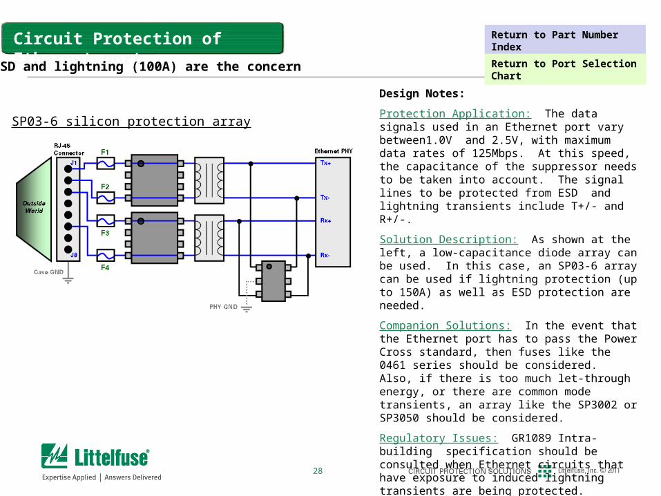
Design Notes:
Protection Application: The data signals used in an Ethernet port vary between1.0V and 2.5V, with maximum data rates of 125Mbps. At this speed, the capacitance of the suppressor needs to be taken into account. The signal lines to be protected from ESD and lightning transients include T+/- and R+/-.
Solution Description: As shown at the left, a low-capacitance diode array can be used. In this case, an SP03-6 array can be used if lightning protection (up to 150A) as well as ESD protection are needed.
Companion Solutions: In the event that the Ethernet port has to pass the Power Cross standard, then fuses like the 0461 series should be considered. Also, if there is too much let-through energy, or there are common mode transients, an array like the SP3002 or SP3050 should be considered.
Regulatory Issues: GR1089 Intra-building specification should be consulted when Ethernet circuits that have exposure to induced lightning transients are being protected.
Unique Features: Does not apply.
Application Warnings: Does not apply.
Circuit Protection of Ethernet port
SP03-6 silicon protection array
ESD and lightning (100A) are the concern
Return to Part Number Index
Return to Port Selection Chart
29
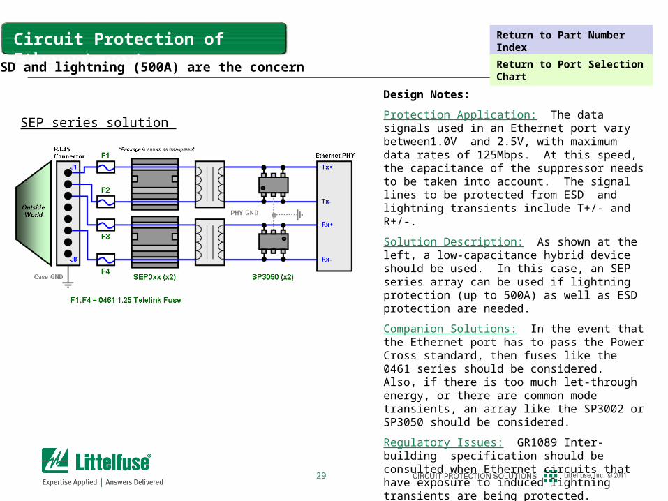
Design Notes:
Protection Application: The data signals used in an Ethernet port vary between1.0V and 2.5V, with maximum data rates of 125Mbps. At this speed, the capacitance of the suppressor needs to be taken into account. The signal lines to be protected from ESD and lightning transients include T+/- and R+/-.
Solution Description: As shown at the left, a low-capacitance hybrid device should be used. In this case, an SEP series array can be used if lightning protection (up to 500A) as well as ESD protection are needed.
Companion Solutions: In the event that the Ethernet port has to pass the Power Cross standard, then fuses like the 0461 series should be considered. Also, if there is too much let-through energy, or there are common mode transients, an array like the SP3002 or SP3050 should be considered.
Regulatory Issues: GR1089 Inter-building specification should be consulted when Ethernet circuits that have exposure to induced lightning transients are being protected.
Unique Features: Does not apply.
Application Warnings: Does not apply.
Circuit Protection of Ethernet port
SEP series solution
ESD and lightning (500A) are the concern
Return to Part Number Index
Return to Port Selection Chart
30
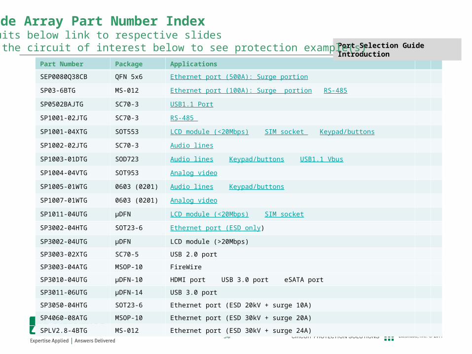
Part Number Index
Part Number Package Applications
SEP0080Q38CB QFN 5x6 Ethernet port (500A): Surge portion
SP03-6BTG MS-012 Ethernet port (100A): Surge portion RS-485
SP0502BAJTG SC70-3 USB1.1 Port
SP1001-02JTG SC70-3 RS-485
SP1001-04XTG SOT553 LCD module (<20Mbps) SIM socket Keypad/buttons
SP1002-02JTG SC70-3 Audio lines
SP1003-01DTG SOD723 Audio lines Keypad/buttons USB1.1 Vbus
SP1004-04VTG SOT953 Analog video
SP1005-01WTG 0603 (0201) Audio lines Keypad/buttons
SP1007-01WTG 0603 (0201) Analog video
SP1011-04UTG μDFN LCD module (<20Mbps) SIM socket
SP3002-04HTG SOT23-6 Ethernet port (ESD only)
SP3002-04UTG μDFN LCD module (>20Mbps)
SP3003-02XTG SC70-5 USB 2.0 port
SP3003-04ATG MSOP-10 FireWire
SP3010-04UTG μDFN-10 HDMI port USB 3.0 port eSATA port
SP3011-06UTG μDFN-14 USB 3.0 port
SP3050-04HTG SOT23-6 Ethernet port (ESD 20kV + surge 10A)
SP4060-08ATG MSOP-10 Ethernet port (ESD 30kV + surge 20A)
SPLV2.8-4BTG MS-012 Ethernet port (ESD 30kV + surge 24A)
Port Selection Guide Introduction
TVS Diode Array Part Number IndexThe circuits below link to respective slidesClick on the circuit of interest below to see protection example(s)