CHARACTERIZATION OF CORROSION RELATED FAILURES
16
CHARACTERIZATION OF CORROSION RELATED FAILURES S. It. Singh Materials Characterization Division National Metallurgical Laboratory Jamshedpur - 831 007 Abstract This paper deals with the characterization of corrosion related failures of structural steel components in the various environments of petrochemical industries. The case studies, pertaining to the failures due to, stress corrosion cracking in CO2 environment, catastrophic carburization (metal dusting corrosion) in hydrocarbon environment , and corrosion fatigue in steam environment have been discussed. The cracking in the linepipe (conforming to IS 1239) was due to grain boundary segregation of Mn and Si leading to hardening in the region just outside the outermost area of HAZ, i.e., SCHAZ and in the parent metal. The service cracking as well as tensile test fracture always occurred in parent metal with different degree of intergranular brittle fracture-The factors that directly affect the occurrence of cracks are due to; segregation of Mn & Si outside the HAZ, longitudinal stress as well as residual stress due to weld and corrosive nature of C02-CO-l I,O system. These three factors satisfies the occurrence of SCC. A failed reactor tube of I.25Cr-0.5Mo steel have been investigated. The characterization of corrosion products revealed the presence of wustite, magnetite, Cr2C, M23C6, rounded metal particles and carbon soot. The morphological feature in the subsurface region revealed highly carburized inner tube metal surface. This carburized layer was indicative of non-protective behavior of oxide scale in the operative temperature and environment. In the thicker region of tube wall, thinning in the form of rounded pits whereas in the thinner region of tube, metal loss in the form of uniform thinning was encountered. All these observations indicate that the metal wastage was due to carburizing condition. The microstructural changes occurred in the steam drum nozzle weld its well as vortex hrcaker weld, made of a commercial HSLA steel (DIN I5NiCuMoNh5) have been investigated. The welds showed predominantly an accicular ferritic microstructure with dislocation substructure which is beneficial for weld toughness. Various types of intragranular and intergranular precipitates have been observed. However, the e-Cu precipitates of about 40 nm were observed which is much higher than the 20 nm size often observed in this class of steel, indicating an overaging effect. Large number of spherical aluminosilicate inclusions containing titanium have also been found. The cracks were revealed by SEM which infers the crack propagation direction. The features and service conditions are indicative of corrosion fatigue cracks. The corrosion fatigue cracking resulted from combination of, i) vibration, ii) susceptible microstructure, and iii) corrosive environment. §1. IN'T'RODUCTION Engineering materials are used in environments that are capable of reacting with the material. Amongst all the structural materials, the low alloy steels certainly outnumber all others. Their combination of strength and ductility and the ability to vary both of these properties by straight-forward heat treatment or compositional changes makes them by far the most versatile material available today. To avoid the affect of the material-environment interactions, metallurgist have long been concerned with failure that occur as a result of this interaction. The materials are expected to show maximum performance, provide long life for maximum economy and at the same time ensure safety and reliability of components and systems. For all this, we need to know the causes of failures which pinpoints to the solution of practical problem. As might be expected, the affect of such interactions arc quite varied in different environment and a catalogue of such an effect fill pages. What we have chosen to do so is to select three environments which have received particular attention in petrochemical industries and concentrate on them. These are, (I) Stress corrosion cracking in CO-) environment, (2) Catastrophic carburization (metal dusting corrosion) in hydrocarbon environment (Zl ('ol'rotiloll fatigue in steam e nvirolllllellt. 1
Transcript of CHARACTERIZATION OF CORROSION RELATED FAILURES
CHARACTERIZATION OF CORROSION RELATED FAILURES
S. It. Singh
Materials Characterization Division
National Metallurgical Laboratory
Jamshedpur - 831 007
AbstractThis paper deals with the characterization of corrosion related failures of structural steel components in
the various environments of petrochemical industries. The case studies, pertaining to the failures due to, stresscorrosion cracking in CO2 environment, catastrophic carburization (metal dusting corrosion) in hydrocarbonenvironment , and corrosion fatigue in steam environment have been discussed.
The cracking in the linepipe (conforming to IS 1239) was due to grain boundary segregation of Mn andSi leading to hardening in the region just outside the outermost area of HAZ, i.e., SCHAZ and in the parentmetal. The service cracking as well as tensile test fracture always occurred in parent metal with different degreeof intergranular brittle fracture-The factors that directly affect the occurrence of cracks are due to; segregation ofMn & Si outside the HAZ, longitudinal stress as well as residual stress due to weld and corrosive nature ofC02-CO-l I,O system. These three factors satisfies the occurrence of SCC.
A failed reactor tube of I.25Cr-0.5Mo steel have been investigated. The characterization of corrosionproducts revealed the presence of wustite, magnetite, Cr2C, M23C6, rounded metal particles and carbon soot.The morphological feature in the subsurface region revealed highly carburized inner tube metal surface. Thiscarburized layer was indicative of non-protective behavior of oxide scale in the operative temperature andenvironment. In the thicker region of tube wall, thinning in the form of rounded pits whereas in the thinnerregion of tube, metal loss in the form of uniform thinning was encountered. All these observations indicate thatthe metal wastage was due to carburizing condition.
The microstructural changes occurred in the steam drum nozzle weld its well as vortex hrcaker weld,made of a commercial HSLA steel (DIN I5NiCuMoNh5) have been investigated. The welds showedpredominantly an accicular ferritic microstructure with dislocation substructure which is beneficial for weldtoughness. Various types of intragranular and intergranular precipitates have been observed. However, the e-Cuprecipitates of about 40 nm were observed which is much higher than the 20 nm size often observed in thisclass of steel, indicating an overaging effect. Large number of spherical aluminosilicate inclusions containingtitanium have also been found. The cracks were revealed by SEM which infers the crack propagation direction.The features and service conditions are indicative of corrosion fatigue cracks. The corrosion fatigue crackingresulted from combination of, i) vibration, ii) susceptible microstructure, and iii) corrosive environment.
§1. IN'T'RODUCTION
Engineering materials are used in environments that are capable of reacting with thematerial. Amongst all the structural materials, the low alloy steels certainly outnumber allothers. Their combination of strength and ductility and the ability to vary both of theseproperties by straight-forward heat treatment or compositional changes makes them by far themost versatile material available today. To avoid the affect of the material-environmentinteractions, metallurgist have long been concerned with failure that occur as a result of thisinteraction. The materials are expected to show maximum performance, provide long life formaximum economy and at the same time ensure safety and reliability of components andsystems. For all this, we need to know the causes of failures which pinpoints to the solution ofpractical problem. As might be expected, the affect of such interactions arc quite varied indifferent environment and a catalogue of such an effect fill pages. What we have chosen to doso is to select three environments which have received particular attention in petrochemicalindustries and concentrate on them. These are,
(I) Stress corrosion cracking in CO-) environment,(2) Catastrophic carburization (metal dusting corrosion) in hydrocarbon environment(Zl ('ol'rotiloll fatigue in steam e nvirolllllellt.
1
A I ; 1 1 It re analysis require judicious choice of characterization methodology which consistcif f'olloWin 1 characterization t echniques.
(I) Optical Mctallography(2) Quantitative Metallography(3) Scanning Electron Microscopy(4) X-ray Diffractometry
)Transmission Electron Microscopy(6) hardness survey(7) Mechanical testing
Depending on the requirement , the characterization methods have been selected . The followingcase studies describe the various methodology to pin point the cause of failure.
§2. STRESS CORROSION CRACKING
2.1. Material and Backgrrluiht fs >Iation:Over the last two years, a LPG recovery plant, have observed cracking at a number of
locations in it portion of 6" diameter inert gas header. The linepipe is made of carbon steel ofIS: 1239 specification. The cracking appear to have occurred in circumferential welds or inHAZ. The linepipe has been in service for last seven years and carries inert gas generated intheir 1. G. plant to various utility points in the unit. They have reported; (1) a marked increasedin the CO2 content of inert gas from 8 vol % to 12 vol % since 1993 onwards, (2) extensiveultrasonic thickness surveys near as well as away from the failure sites revealed uniformthickness, thereby, eliminating any possibility of general / localized corrosion due to themedium, (3) during hydrotcst, leakage was observed from one of the scans which was rectifiedby using seamless pipe and further welding while this appeared to be a solitary case, it doespoint to some inherent defect in the said pipe segment, either due to faulty material orfabrication.. Three samples of linepipe have been investigated. The samples "A" and "B" haveundergone cracking failure and taken from different locations whereas the sample "C" is anuncrackcd but undergone same service exposure. The details of service conditions andmaterials specifications are as follows;
Lincpipe Material : Carbon steel conforming IS: 1239(minimum UTS = 320 MPa, % elongation > 20 %,S < 0.05 % and P < 0.05 %).
Pressure 7 kg/cm2."l'empcraturc : 40 °C.Gas composition Nitrogen
Carbon dioxideOxygenCarbon monoxide
88 vol%.12 vol%.0.5 vol%.< 0.5 vol%.
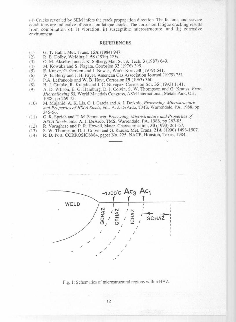
The heat affected zone (HAZ) of the single cycle weld can be classified,microstructurally, into four regions depending on the peak temperature experienced. These aregrain coarsened IIAZ (GCIIAZ) experiencing temperature above 1 100 °C, grain refined I IAZ(GRHAZ) facing tell) perature between 1 100 °C to Act, intercritical IIAZ (ICIIAZ) betweenAct to Acs and subcritical HAZ (SCHAZ) formed at temperature lower than Acs. A schematicillustration of the weld-HAZ microstructural regions of a single pass weld is shown in Fig. 1.
Stress corrosion cracking (SCC) of carbon and low alloy steel is a significant problemfor a variety of industries, such as those dealing with power generation, oil and gas, refiningand pipeline transmission. SCC is particularly insidious in that catastrophic failures can occureven at low applied stress level (sometimes only residual in nature) and often has no warning.Environment causing SCC can be so mild that no evidence of corrosion can be detected exceptSCC itself. For SCC to occur in any material, he following three conditions must be satisfied,i.e., (I) sufficient level of tensile stress, (2) a corrosive medium, and (3) susceptiblemicrostructure.
The drv carbon dioxide is noncorrosive to metals and alloys. However in tlie presenceof water, C•02 forms weak carbonic acid which is corrosive. Most oil and gas production has,is s ciatcd water production, either formation or condensation. CO2 corrosion is normally ofthe weight loss type, but CO2 can, in presence of carbon monoxide (CO) and water, result in

stress corrosion cracking (SCC) of susceptible metals. Mixture of C02, CO and water cancause SCC of plain steels and low alloy steels(4.5). The origin of failure usually beingassociated with localized corrosion on steels with high Mn-contents.
§2.2. Characteristics of CO-CO2 Stress Corrosion Crackiue:Based on the experimental program supported by Pipeline Research Committee of
American Gas Association, the following characteristics are pertinent to CO-CO2 stresscorrosion cracking of gas transmission pipelines(').(I) CO. CO2 and H2O must be present for SCC.(2) CO2 & CO partial pressures as low as 1 psi can promote CO-CO2 SCC of pipeline
steel.(3) Oxygen greatly increases the severity of SCC.(4) The severity of SCC increases with increasing CO, C02, decreasing CO, anodic
polarization and increasing 02-(5) Steels with Cr-content greater than 9% have not been shown to be susceptible to LO-
CO, SCC.
§2.3. General Characteristics of SCC Features:The following criterion provide it general characterization of SCC features.
(I) SCC represents a brittle rupture . Brittle fracture and an absence of plastic deformationshould generally be present.
(2) Stresses required for SCC arc usually small ( below the macroscopic yield stress) andare static and tensile in nature . Applied stresses often add to a residual stress condition.
(3) SCC cracks initiate on the surface , and numerous initiation sites are possible (incontrast with mechanical failures, which usually have a single preferred site).
(4) As is characteristic of brittle failures, the general crack path is usually aligned normal tothe tensile axis.
(5) There usually is minimal evidence of corrosion damage. However, surface staining onexposed surfaces may be present.
(6) SCC is a progressive type of fracture, i.e., cracks grow gradually over a period oftime. ;
§2.4. Experimental;
§2.4.1. Visual examination & dimensional measurements : The 6" dia headerlinepipes were having circumferential weld. The linepipes A & B showed cracks runningparallel to weld while linepipe C was a sound tube. All the external surfaces of linepipes wereprotected by yellow paint. Figure 2 showed a photograph of cracked lincpipe where the crackis marked by arrows. The extent of the cracks were about 3" - 4 ". The internal surface of allthe tubes exposed to the carrier gases showed adherent brown deposit. The measured dia of thelinepipes were 16.5 cm. The carrier gas internal pressure of 10 kg/cm2 (0.98 MPa) would giverise to hoop stress (tangential stress), 61,p„p = 16.2 MPa and longitudinal stress, alnngirudinal =8.1 MPa. As the cracks were along the circumference, therefore, the longitudinal stress wouldbe operative on cracks,
§2.4.2. Chemical analysis : The composition conforms to IS: 1239 which specify that thephosphorous and sulfur should be less than 0.05%. As shown in the table I,the weld metal hashigher concentration of Mn and Si as compared to the parent metal. The parent rectalcomposition of linepipe B differs from that of A and C in respect of Cr and Si concentration.Therefore the linepipes A and C might belong to same group which certainly differs from thegroup comprising of linepipe B.
§ 2.4.3. Optical metallography and SEM studies : The samples A/B and C wereexamined for location of cracks and its corresponding microstructural characteristics. Themicrostructures of weld, Different areas o f f IAZ [consisting of coarse grained HAZ. (CC;I IAZ),grain refined I IAZ (GRIIAZ), intercritical I IAZ (ICIIAZ) and subcritical I IAZ (SCI IAZ)J andnearby base metal were characterized. No defects were found in the weld and HAZ. The cracks
3
were about 2-3 mm away from the SCIIAZ and in base instal. The base ntelal near crackcontains grain boundary phases termed 'dark phase' (Fig. 3) because of its atomic numbercontrast in hack scattered electron images. The conlposilion of dark phase and nearby ferritegrains were determined by EDAX. 't'his showed significant segregation of Si and Mn in thedark phase (Table 2). The microhardness of dark phase was much higher than the nearbyferrite grains (Table 3). All these observation showed hardening of grain boundary phase wasdue to segregation of Mn and Si. The dark phase was only observed in cracked samples. Theabsence dark phase in virgin sample indicates that its formation occurred during servicecxposurc.
'f'able l: Chemical composition (wt%) of weld and parent metal of Iinepipe.
Pipe Area C Mn Si P S Cr Cu Ni FeA Parent 0.09 0.51 0.03 0.03 0.020 n.f. 0.0070 0 . 004 balanceA Weld 0.13 1.22 0 .45 0.04 0 . 018 n.1'. 0.016 0.01 balance13 Parent 0 . 11 0.54 0 . 12 0.007 0.020 0 . 009 0 . 0085 0.005 balanceB Weld 0.11 1.24 0 . 46 0.016 1 0.0 1 0 . 0085 0.0093 0.006 balanceC Parent 0 . 11 0.53 0.02 0.02 0.021 n . f. 0.007 0.005 halancc(' C Iii (t_ I 3 I .'_) O.5^) O.O t O.O I 1 n.f. ().()1 ().()()0 balance
n.f. = not linmd
§2.4.4. Compositional analysis by EDAX: The samples from pipelines A, B & C wereanalyzed for the partitioning of alloying elements among the various microstructural features byenergy dispersive analysis of X-rays (EDAX). The data were collated in table 2. It is evidentthat the grain boundary dark phase present in the neighborhood of cracks were richer in Si andMn as compared nearby ferrite grains. The Si enrichment was 3-4 times and Mn enrichmentwas about 2-3 times of the ferrite grain interior.
'f'able 2: EDAX composition for partitioning of elements.
S. N o Area S i Mn Fe S Remarkswt% wt% wt% wt%
1 Weld pool 0.30 1.03 98.67 * Area analysis
2 HAZ 0.19 0.95 98.86 * Area analysis
3 Near crack 0.07 0.75 99.17 * Area analysis
4 Dark phase 0.44 1.13 98.43 * Point analysis(i e-B)
5 Dark phase 0.36 1.40 98.24 * Point analysis(pi-A)
6 Ferrite grain near 0.10 0.5 2 99.38 * Point analysiscrack (i e-B)
7 Ferrite grain near 11.12 0.56 99.33 * Point analysiscrack (pi pe-A)
8 Elongated silicate 15.32 36.64 46.69 1.35 Point analysisinclusions
Inclusions in *F * Point analysis
fracto rahI
MnS inclusions
* below minimum detectable limit.
§2.4.5. 111icrohardness measurements : Vickers microhardness measurements weremade on a metallographically polished samples from failed pipeline A and B, at a load of 100g. The measurements were collated in table 3. A general hardness survey were also made onlarge nunnher of samples from failed pipelines A. B as well as virgin pipeline C, with Vickers
,I.
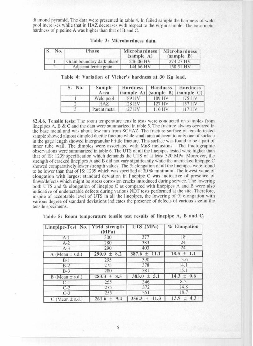
diamond pyramid . The data were presented in table 4 . In failed sample the hardness of weldpool increases while that in I IAZ decreases with respect to the virgin sample . The base metalhardness of pipeline A was higher than that of B and C.
Table 3: 11Iicrohardness data.
S. No. Phase Microhardness(sample A)
Microhardness(sample 11)
I Grain boundary dark phase 246.06 I I V 274.27 1 I V2 Adjacent ferrite grain 144.66 HV 158.51 I-IV
'fable 4 : Variation of Vicker ' s hardness at 30 Kg load.
S. No. SampleArea
Hardness(sample A)
Hardness(sample B)
Hardness(sample C)
I Weld pool 189 1 I V 189 1 I V 175 I I V2 IIAZ 12811V 12711V 1571IV3 Parent metal 127 1 IV 116 HV 117 I I V
§2.4.6. Tensile tests: The room temperature tensile tests were conducted on san ► plcs fromlinepipes A, B & C and the data were summarized in table 5. The fracture always occurred inthe base metal and was about few mm from SCI IAZ.. The fracture surface of tensile testedsample showed almost dimpled ductile fracture while small area adjacent to only one of surfacein the gage length showed intergranular brittle fracture. This surface was found to be a part ofinner tube wall. The dimples were associated with MnS inclusions . The fractographicobservations were summarized in table 6. The UTS of all the linepipes tested were higher thanthat of IS: 1239 specification which demands the UTS of at least 320 MPa. Moreover, thestrength of cracked linepipes A and B did not vary significantly while the uncracked linepipe Cshowed comparatively lower strength values. The % elongation of all the linepipes were foundto be lower than that of IS: 1239 which was specified at 20 % minimum. The lowest value ofelongation with largest standard deviation in Iinepiptr C was indicative of presence offlaws/defects which might be stress corrosion cracks introduced during service. The loweringboth UTS and % elongation of linepipe C as compared with linepipes A and B were alsoindicative of undetectable defects during various NDT tests performed at the site. Therefore,inspite of acceptable level of UTS in all the linepipes, the lowering of % elongation withvarious degree of standard deviations indicates the presence of defects of various size in thetensile specimens.
Table 5: Room temperature tensile test results of linepipe A, It and C.
Linepipe- Test No. Yield strength(M Pa)
UTS (MPa ) % Elongation
A-1 300 377 18A-2 280 383 24A-3 290 403 24
A (Mean ± s.d.) 290 . 11 ± 8.2 387 . 6 ± 11.1 18.5 ± 1.1
13-1 295 390 13.613-2 275 378 14.113-3 280 381 15.1
It (Mean ± s.d.) 283.3 ± 8.5 383 .0 ± 5.1 14.3 ± 0.6C-I 255 346 8.3
C-2 275 372 14.8
(,-3 255 351 18.7-C (Mean ± s.d.) 261.6 _t 9.4 ;56 .3 ± T77 13.9 ± 4.3[
5
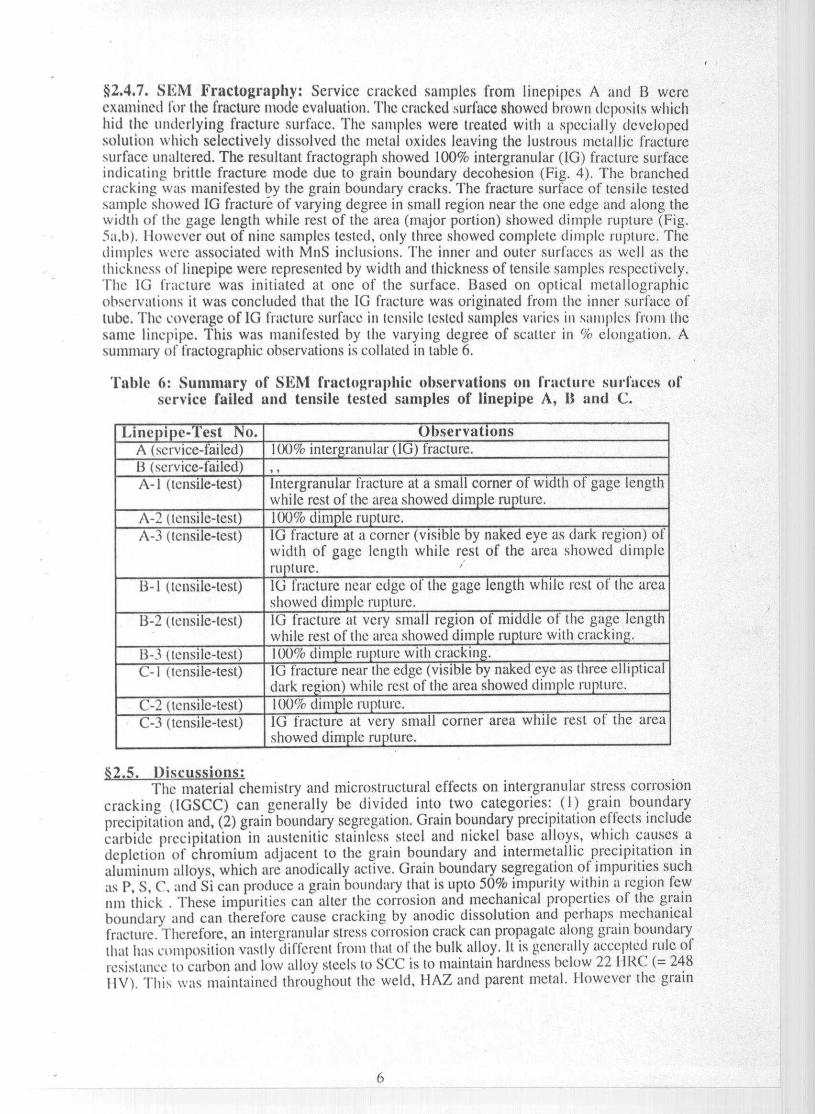
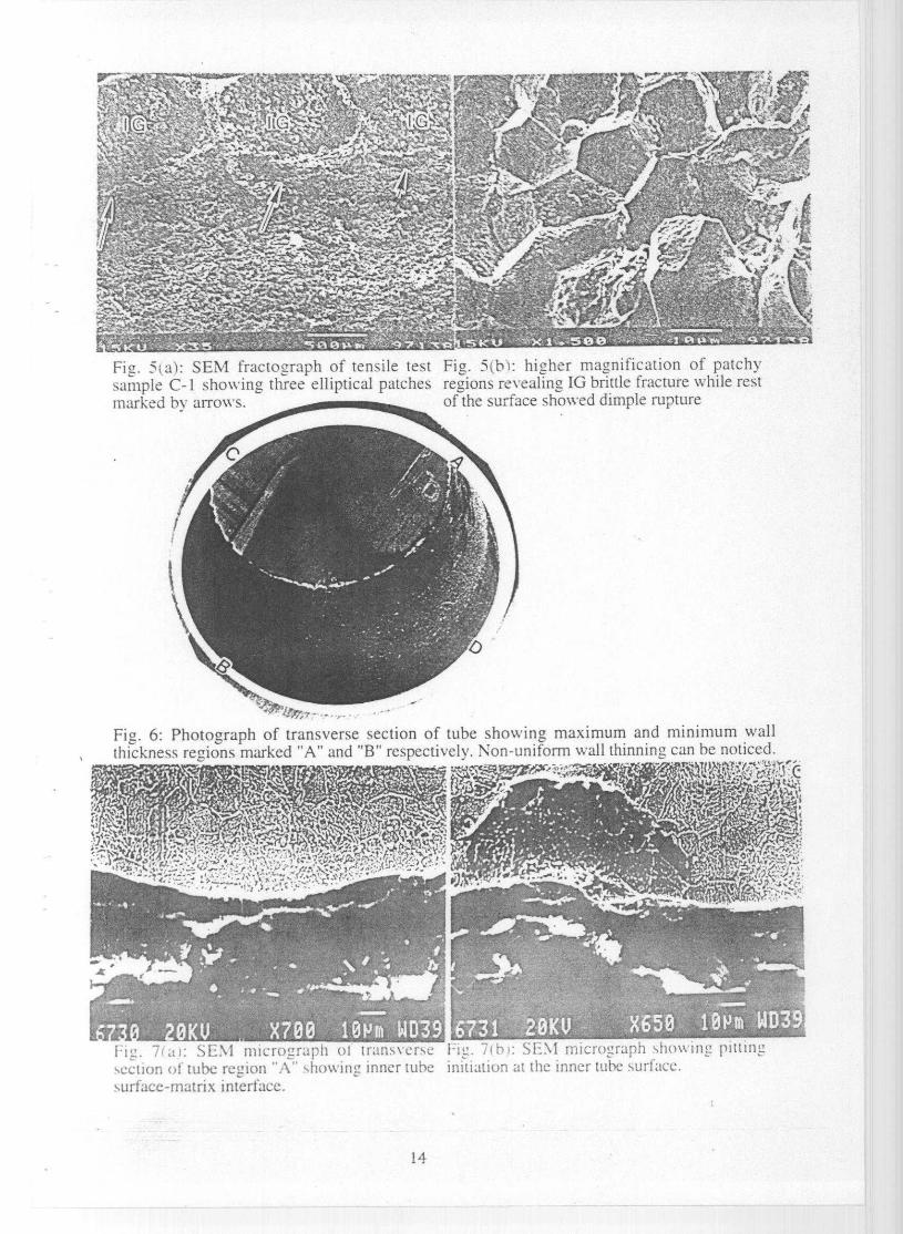
§2.4.7. SE M Fractography : Service cracked samples from linepipes A and B wereexamined for the fracture mode evaluation. The cracked surface showed brown deposits whichhid the underlying fracture surface. The samples were treated with a specially developedsolution which selectively dissolved the metal oxides leaving the lustrous metallic fracturesurface unaltered. The resultant fractograph showed 100% intergranular (IG) fracture surfaceindicating brittle fracture mode due to grain boundary decohesion (Fig. 4). The branchedcracking was manifested by the grain boundary cracks. The fracture surface of tensile testedsample showed IG fracture of varying degree in small region near the one edge and along thewidth of the gage length while rest of the area (major portion) showed dimple rupture (Fig.5a,b). Ilowever out of nine samples tested, only three showed complete dimple rupture. Thedimples were associated with MnS inclusions. The inner and outer surfaces as well as thethickness of linepipe were represented by width and thickness of tensile samples respectively.The 1G fracture was initiated at one of the surface. Based on optical nictallographicobservations it was concluded that the 1G fracture was originated from the inner surface oftube. The coverage of IG fracture surface in tensile tested samples varies in samples from thesame linepipe. This was manifested by the varying degree of scatter in % elongation. Asummary of fractographic observations is collated in table 6.
'['able 6: Summary of SEM fractographic observations on fracture surfaces ofservice failed and tensile tested samples of linepipe A, 13 and C.
Linepipe -Test No. ObservationsA (service-failed) 100% inter granular (1G) fracture.13 (service-failed) , ,A- I (tensile-test) intergranular fracture at a small corner of width of gage length
while rest of the area showed dimple rupture.A-2 (tensile-test) 100% dimp le ru pture.A-3 (tensile-test) IG fracture at a corner (visible by naked eye as dark region) of
width of gage length while rest of the area showed dimplerupture. '
B-1 (tensile-test) IG fracture near edge of the gage length while rest of the areaShowed dim p le I'll )titre.
B-2 (tensile-test) IG fracture at very small region of middle of the gage lengthwhile rest of the area showed dimple rupture with cracking.
13-3 (tensile-test) 100% dull Ie rupture with cracking.
C-I (tensile-test) 1G fracture near the edge (visible by naked eye as three ellipticaldark region) while rest of the area showed dimple ru lure.
C-2 (tensile-test) 100% dim le rupture.C-3 (tensile-test) IG fracture at very small corner area while rest of the area
showed dimple rupture.
§2.5. Discussions:The material chemistry and microstructural effects on intergranular stress corrosion
cracking (IGSCC) can generally be divided into two categories: (1) grain boundaryprecipitation and, (2) grain boundary segregation. Grain boundary precipitation effects includecarbide precipitation in austenitic stainless steel and nickel base alloys, which causes adepletion of' chromium adjacent to the grain boundary and intermetallic precipitation inaluminum alloys, which are anodically active. Grain boundary segregation of impurities suchas P, S, C, and Si can produce a grain boundary that is upto 50% impurity within a region fewnm thick . These impurities can alter the corrosion and mechanical properties of the grainboundary and can therefore cause cracking by anodic dissolution and perhaps mechanicalfracture. Therefore, an intergranular stress corrosion crack can propagate along grain boundarythat has composition Vastly different from that of the hulk alloy. It is generally accepted rule ofresistance to carbon and low alloy steels to SCC is to maintain hardness below 22 I IRC (= 248I1V). This was maintained throughout the weld, HAZ and parent metal. However the grain
6
boundary segregation outside the HAZ region resulted in the hardness increase in the localizedarea creating conditions susceptible to SCC.
§2.6. Conclusions:The cracking in the linepipe was due to grain boundary segregation of Mn & Si leading
to hardening in the region just outside the outermost area of HAZ. i.e.. SCHAZ and in the basemetal. The rigidity of restrained joints can cause cracking. The factors which directly affect theoccurrence of cracks are due to compositional factors rather than procedural factors related withwelding operations. The surest method for control of CO-2-CO-H2O SCC is to preventcondensation by controlling gas composition and keeping the service temperature above thedew point.
§3. CATASTROPHIC CARBURIZATION (METAL DUSTING)
0.1. Material and Background Information:A failure of reactor tube made of 1.25Cr-0.5Mo steel had occurred after a service of
67,000 hours. The failed 6" dia Pacol reactor tube conforms to Sch. 40 ASTM A335-P11. Inthe process the paraffin hydrocarbon mixed with recycled hydrogen goes into Pacol reactor invapor state. The material and service conditions are summarized below;
Alloy composition:Dimension of tube:Temp. of outer surface:
Atmosphere around tube:Fluid inside tube:Inlet temp. of paraffin:Outlet temp. of Paraffin:Pressure inside tube:
Conforms to Sch. 40 ASTM-A335-P 11 (1.25Cr-0.5Mo steel).168.3 mm OD x 7.2 mm thick.Heater inside temperature is 1200 °C near burner combustionzone and is gradually comes down to about 700 °C in convectionzone of the heater.Hot air due to combustion of fuel at normal atm. pressure.Paraffin.380 °C490°C2 Kg/cm2.
In petrochemical industries, the life controlling conditions are usually governed by;(1) Creep rupture damage.(2) Thermal shock-
In addition toy creep damage, and the effects of the higher temperatures, the life of coilalloys is also dependent on; (1) Carburization, (2) Oxidation, (3) Thermal shock due tocycling.
Carburization is observed in several industrial processes under carbonaceousatmosphere at high temperature. Carbon is transferred from gas atmosphere to the alloy matrix,and internal carbides are formed. Usually, the alloys are protected against carburization by anoxide layer barrier against carbon ingress. The oxide scale breakdown occur by chemicalreaction or mechanical failure. Metal dusting is a catastrophic carburization (7.8) which is aparticularly aggressive form of high temperature corrosion of Fe, Co and Ni based alloys bysulfur free mixtures of hydrocarbon in which metal disintegrates into dust of metals. metalcarbides. oxides and carbon. This phenomenon is dependent on large number of factors. i.e.,gaseous phase composition, temperature, pressure, alloy type and component shape. This is aform of rapid metal wastage in carbonaceous gas streams e.g., CO/CO,, hydrocarbons etc.,generally in the temperature range 400 - 800 °C. The wastage is often in the form of roundedpits, but in some cases metal loss in the form of uniform thinning is encountered, particularlywhere gas velocities are high. The surface from which metal is lost are generally carburized, infact, in almost every case where wastage is of the pitting type, though often it is more difficultto detect carburization if the wastage is of uniform variety in high velocity gas stream- Theinitiation of carburization process is manifested by presence of sooty deposit containingcarbon, metal particles, metal carbide and oxides. This is known to occur with materials basedon the Fe. Cr and Ni which are known to have pronounced catalytic effects on the breakdownof CO and hydrocarbon in certain high temperature ranges.
7

*3.2. Characteristics of Catastrophic Carburization:The common characteristics of catastrophic carburization (metal dusting corrosion) are
sum marized below;Environment: A Ras phase, potentially carburizing and reducing, with or
without oxygen-containing components.Temperature: 400 - 800 °C.Form of deterioration: Localized or general pitting, or more general overall wastage.
The surface from which metal is lost are carburized.Corrosion products: Dust or powder component of carbon mixed with metal, metal
carbides, and metal oxides.
$3.3. Experimental:
§3.3.1. Visual examination : The transverse section of failed tube is shown in Fig. 6.Wall thickness of tube was non-uniform having maximum thickness of 6.8 mm (region "A")and minimum thickness of 3.6 mm tregion "B"). These two regions are diametrically oppositeand outer diameter across it was 170 mm while outer diameter perpendicular ("CD") to it was168 mm. Inner tube surface has dull black appearance with sooty deposits. Therefore the tubehad undergone 1% expansion along "AB", where wall thinning was maximum while there wasno appreciable deformation along "CD". These observations indicate that the failure wouldhave taken place due to non-uniform wall thinning.
§3.3.2. Optical metallography : Microstructures of base metal as well as matrix/scaleinterface, in transverse section of tube, were analysed. The matrix have usual microstructureconsisting of ferrite and tempered bainite. The scale at outer surface was thicker, compact andundamaged with no significant changes in subsurface matrix microstructure, while scale atinner rube surface showed thinner/broken scale with altered subsurface microstructure. Theseobservations indicate that there was breakdown of protective scale which lead to the alterationof subsurface matrix microstructure at the inner wall of tube.
§3.3.3. Scanning electron microscopy & composition analysis by EDAX: Theinner tube surface/matrix microstructure from transverse section of region "A" is shown in Fig.7a, which showed the duplex nature of oxide scale consisting of thin inner wustite layer andthick outer magnetite/spinel layer. Ingress of carbon to subsurface region lead to generalcarburization manifested by intergranular as well as intragranular carbideprecipitation/coarsening and initiation of pitting (Fig. 7b). The longitudinal section of innersurface showed (Fig. 8) spherical particles dispersed on irregular shaped particle/soot. SEM oftransverse section from region "B" showed unaltered matrix microstructure (Fig. 9a) whilesubsurface region of inner tube wall showed (Fig. 9b ) coarsening of grain boundaryprecipitates as well as increase in their number density . Also the pitting in region "B' wasabsent . This indicates that the uniform metal wastage by catastrophic carburization wasoperative in the region "B".
EDAX analysis of various microstructural constituents have been performed to assesthe elemental partitioning. A comparison of composition of base metal with carburized zoneshowed some enrichment of Mo, Cr and decrease of Si content in carburized zone. The innerand outer oxide scales were enriched with Mo and Si, while Cr content decreased in bothscales. The spherical metal particles were also enriched with Mo but Cr content was decreasedwith respect to base metal.
§3.3.4. X-ray diffraction analysis: The analysis of diffractograms, recorded with CoKaradiation, from samples of region "A" revealed the presence of ferrite, wustite, magnetite,Cr-2C, M23C6 and carbon soot. The ferrite peaks originated from base metal as well asspherical metal particles which were formed due to carburization of base metal. NVustite isstable above 570°C and Cr. Mo raises its stability to 600'C. Therefore the presence of wustitein the scale indicates that the region of tube had experienced temperature in excess of 600°C.The absence of hematite. which grow in presence of water vapor and thermodynamicallyunstable to high reducing gas atmosphere, was consistent with the environment in the tube.
9

The XRD analysis of samples from region "B" showed the presence of ferrite, magnetite,Cr2C, M,3C6 while wustite peaks were absent and carbon soot was negligibly small.
3.4. Discussions:In catastrophic carburization, i.e., metal dusting, the reaction products arc; carbon,
carbides and oxides, interspersed with metal particles (poor in Cr). These corrosion productsMV loosely adherent and can be easily eroded, which lead to, pitting or uniform thinning. Thecarburization involve following kinetic steps; (l) transport in gas atmosphere by gasflow/diffusion, (2) carbon transfer to the metal phase by phase boundary reaction which arcleaction of the gas molecules on the surface, leading to carbon atoms, (3) inward diffusion ofdissolved carbon in the metal , (4) reaction of carbon with carbide forming elements in tfee alloyinterior, and diffusion of carbide forming elements to precipitates.
't'herefore, carburization resistance can he developed either, (I) by addition of enoughsilicon ( 1.5 - 311"e) to form nmrc or less continuous sublaycr of S102 beneath the oxide layerwhich is thermodynamically more stable than oxide and is not attacked by carbon, or, (2) bypresence ()['sulfur which slows down the carbon transfer to the metal surface.
0.5. Conclusions:Based on the structural, microstructural and compositional studies conducted on the
inside tube wall, the following conclusions can be inferred.I ) Carburization was manifested by the presence of carbides Cr2C and M23C6 at the surface
and subsurface regions . (2) Phase identified in the region "A" arc; ferrite, magnetite, wustiteCr2C, N121C6 and carbon soot while in region "B", wustite and carbon soot are absent. (3)Catastrophic carburization in region "B" was of uniform metal wastage type whereas in region"A", it was of pitting type.
Addition of 112S/CS2 gas stream acts as catalytic poison for decomposition ofhydrocarbon, thereby decreasing the carbon activity and block the ingress of carbon to metallicsurface Which inhibit carhurization process. The material replacement with 5Cr- I Mo/9Cr- I Mocan also results in reduced carhurization.
§4. CORROSION FA' T'IGUE
§4.1. Material and Background Information:At a petrochemical industry, twelve naphtha cracking furnaces and three recycle
furnaces were commissioned in March 1997. The leakage in the steam drum was detected inFebruary 1998. During the service period of one year, the drums have experienced seven startup/shut down cycles. The leakages occurred from the through thickness cracks in the welded.joints. Large number of radial cracks in the steam drum down coiner nozzle welds originatedfrom the inside surface of the steam drum. These cracks were aligned to the longitudinaldirection of the steam drum. From their orientation it was clear that all the cracks had developedunder the influence of hoop stress and were associated with locally increased stress level. Thedetails of, service conditions and materials specifications are as follows;
Steam drum shell & nozzle Material IISLA steel conforming to DIN designation15 NiCuMoNb 5
Operating temperature 3(X) °COperating pressure : 1 10 atnl.Stea m drum s ize : 3 111 X 1 .6 niO with a wall thickness of 45 nun.
The IISLA steel with good combination of strength, toughness and weldahility isusually alloyed with nickel chromium, manganese, nlolybdenunl, niohiunl and copper. Most ofthe elements provide hardenebilty for the transformation of austenito to fine ferriticmicrostructure in heavy sections. In addition, the strength is enhanced by the precipitation ofcopper and niobium carbide. This class of steel can he processed to have excellent propertieshowever. problem may still be encountered during welding, in the heat affected zone (I IAZ) aswell as in the weld metal. The matrix pleases in the I IAZ transform to austenite and precipitate
coarsen or dissolve during heating cycle; then the matrix will transform to martensite,ferrite. and/or hainite with new precipitate distribution upon cooling 0-11). "These changes may
degrade the mechanical properties (e.g., strength, hardness and toughness) of the weldedstructure. Although there have been a number of studies of HSLA steels within the last tenyears. many of these studies have dealt only with mechanical properties supplemented byoptical microscopy and/or SIN to correlate the r ► ticrustruclure with the properties. 'I'I;M studiesusually focused on the effects of alloying elements and/or isothermal aging treatments on themicrostructure (10.12) or on the development of continuous cooling transformation (CCT)curves 01.1'1. I lowever there is still no clear understanding of the detailed n ► icrostructureswhich give rise to the property variation across the weld-HAZ as a function of positioned weldcondition. e.g., heat input and preheat.
With these limitations in mind, the present investigation was thus undertaken to studysystenrilically, the detailed microstructural changes which occurred in the weld-I IAZ, of thisclass of I ISI,A steel.
Several failure mechanism have been proposed for the dcacrator and steam drumcracking process, including corrosion fatigue cracking, stress corrosion cracking (SCC), strainaging, weld defects, and hydrogen enlbrittlenlent. Most reported case studies havesubstantiated the corrosion fatigue mechanism. Corrosion fatigue refers to the propagation ofwedge shaped crack through a metal resulting from cyclic tensile stresses in it corrosiveenvironment. Corrosion fatigue damage frequently occurs in boilers that are in peaking service,operated discontinuously, or operated cyclically. Susceptibility to corrosion fatigue may beenhanced if rapid start ups or shut downs are practiced. Decreasing these rates has alleviatedsome corrosion fatigue problems in boilers (14). There is one general rule that the greater theuniform corrosion rate the shorter the resultant fatigue life. Therefore metal resistance tocorrosion fatigue is associated with its inherent corrosion resistance rather than high mechanicalstrength. For corrosion fatigue to occur in any material, the following three conditions must hesatisfied. i.e., (1) sufficient level of cyclic tensile stress, (2) a corrosive medium, and (3)susceptible microstructure.
§4.2. Characteristic Features of Corrosion Fatigue:The corrosion fatigue cracks have following characteristics.
(1) Wedge-shaped cracks (funnel-mouthe(l) initiated at pit base and filled with corrosionproduct.
(2) (Blunted tip.(3) Transgranular fracture.(4) Limited or no crack-branching.
The crack growth is not one of electrochemical dissolution of metal atoms at the base ofthe crack . Instead it involves a process of plastic deformation accelerated by corrosionprocess. This effect is not specific to chloride ions but occurs with any corrosive environment.
§4.3. Experimental:
§4.3.1. Transmission electron microscopy : An extensive thin foil transmissionelectron microscopy (TEM) examination of all the three weld-HAZ (two vortex breaker weldand a nozzle weld) and parent metal have been carried out. The objective of TEM study was onfinding out the microstructural constituents which might have caused the cracking in the welds.
The general microstructure parent metal (PM) consisted of ferrite - bainite withintragranular. precipitates of r-Cu and cuboid carbonitrides as well as intergranular M1C andh17CI. Figure 10 showed it low magnification bright field (BF) micrograph.
The microstructure of vortex breaker weld- I showed (Fig. I I) mainly accicular ferrite
with dislocation substructure within the ferrite plate and above mentioned precipitates. Figure12 showed higher magnification view of a blocky ferrite grain revealing distribution r-Cuprecipitates. The average size of these precipitates is about 40 nun and it showed no sign straincontrast around the precipitates. The electron diffraction analysis in conjunction withmorphological observations indicates that the precipitates on packet boundaries are cementite.
The general nlicrostructure of vortex breaker weld-2 was found to he similar to that ofvortex breaker weld- I. For the sake of clarity, the microstructure corresponding to SCI IAZ,ICHAZ and GRHAZ have been analysed. SCHAZ showed typical ferritic microstructurewhile in the ICI IAZ microstructure, ferrite was surrounded by large number of intergranular
1U

carbide precipitates. The GRHAZ microstructures showed inter- and infra-granular carbideprecipitation akin to tempered microstructure. The weld metal showed typical accicular ferriticnlicrostrleturc with dislocation substructure.
The nozzle weld-3 also showed microstructure similar to vortex breaker weld- I & 2.lowever. it showed distribution of spherical aluminosilicate incb .lsions.
`4.3.2. Scanning electron microscopy : A low magnification SEM micrographalongwith a schematic diagram of cracks in the sample 413E is shown in Fig. 13. This samplecover the entire region of vortex breaker weld pool and nozzle weld pool with interveningHAZ. The crack initiated (marked by arrow) in vortex breaker weld pool and propagatedtoward ends A & 13. The crack propagating towards the end 13 followed the two path; theshorter length crack ended in the weld pool itself while the other longer crack propagated in theneighboring HAZ. A higher magnification montage of photographs is shown in Fig. 14. Alocalized parallel crack, marked "PC", parallel to main crack is indicated. The featuresassociated with these cracks were indicative of corrosion fatigue crack.
§4.4. Discussions:The above results show that the austenite in the HSLA steel transform to largely ferritic
n ► icrostructure with variable morphologies and substructures in different regions (differentcooling rates) of the weld. Accicular ferrite is defined as a highly substructured, non-cquiaxedferrite that forms on continuous cooling by a mixed diffusion and shear mode oftransformation. The level of dislocation density in the accicular ferrite is somewhat lower thanthat for niartensite. The accicular ferrites were arranged in packets with cementite particles atthe packet boundaries. Since grain boundary cementite is known to he an embrittler, thesecementite precipitates may provide potential fracture path. Higher carbon HSLA steel which areoften associated with thicker plate gages would he most susceptible to this problem. Theblocky ferrite usually contains a high density of c-Cu precipitates of about 40 nm which ismuch higher than the 20 nm size often observed in this class of steel . The larger size of c-Cuprecipitates may be due overaging effect,
In general terms, the tensile properties of weld metals (with accicular ferrite) are oflesser importance than impact toughness except that a restriction on hardness in welds for pipeintended for sour gas/oil service, usually to it maximum value of 248 VHN, may place somepractical limit on UTS. -Consequently, there has been relatively much more attention toimproving toughness and little need to consider, in detail, strengthening mechanism in this typeof microstructure. There is a critical range in weld metal oxygen content for optimumtoughness. as a consequence of this effect the interlocking of accicular ferrite will determine theoverall toughness of the weld.
The branching of crack or parallel cracking associated with main cracks are indicativeof stress corrosion cracking and corrosion fatigue respectively. The corrosion fatigue crackingresults from combination of, i) vibration, ii) susceptible microstructure, and iii) corrosiveenvironment. Such fine parallel cracking usually result from alternating stresses, possiblycaused by pressure fluctuations or the effect of water hatnnmer, as well as simple vibration.Repeated expansion and contraction as a result of considerable temperature fluctuations mayshow similar effects. Corrosion fatigue cracks which result from this cause, arc often initiatedat small corrosion spots and develop in a transcrystalline manner in contrast to the cracksresulting from stress corrosion which are mainly interctystalline.
§4.5. Conclusions:The following conclusions can he derived from the experimental findings and
discussions.( I ) \Veld inicrost-ucture showed predominantly accicular ferrite with dislocation substructurewhich is a desired microstructure. However, the tempered microstructure in theGRI I AZJIC'I IAZ may affect the mechanical properties of the welds.(2) The high density Oft-Cu precipitates of average size of 40 nni were observed which ismuch higher than the 20 urn size often observed in this class of steel. The larger size of c-Cuprecipitate. may he due ovcraging effecl.(3) Splice W;II aluniinosilicatc inclusions containing titanium have been observed in the weld-3.fill, nlav influence the nlech;ulical I,IOlWrlies of the welel.
II
(4) Cracks revealed by SEM infers the crack propagation direction. The features and serviceconditions are indicative of corrosion fatigue cracks. The corrosion fatigue cracking resultsfrom combination of. i) vibration, ii) susceptible microstructure. and iii) corrosiveenvironment.
REFERENCES
(1) G. T. Hahn. Met. Trans. 1SA (1984) 947.(2) R. E. Dolby, Welding J. 58 (1979) 225s.(3) O. M. Akselsen and J. K. Solberg, Mat. Sci. & Tech. 3 (19S7) 649.(4) M. Kowaka and S. Nagata. Corrosion 32 (1976) 395.(5) E. Kunze, G. Gerken and J. Nowak, Werk. Korr. 30 (1979) 641.(6) W. E. Berry and J. H. Payer, American Gas Association Journal (1979) 251.(7) P.A. Lefrancois and W. B. Hoyt, Corrosion 19 (1963) 360.(8) H. J. Grabke, R. Krajak and J. C. Novapaz, Corrosion Sci. 35 (1993) 1141.(9) A. D. «'Ilson, E. G. Hamburg, D. J. Colvin. S. W. Thompson and G. Krauss. Proc.
Alicroalloving 88, World Materials Congress, ASM International, Metals Park. OH,1988, pp 269-75.
(10) M. Mujahid, A. K. Lis, C. I. Garcia and A. J. DeArdo, Processing, Microstructureand Properties of HSLA Steels, Eds. A. J. DeArdo. TMS. Warrendale, PA, 1988, pp345-56.
(11) G. R. Speich and T. M. Scoonover, Processing. Alicrostructure and Properties ofHSL4 Steels, Eds. A. J. DeArdo, TMS, Warrendale, PA. 1988, pp 263-85.
(12) R. Varughese and P. R. Howell, Mater. Characterisation, 30 (1993) 261-67.(13) S. W. Thompson, D. J. Colvin and G. Krauss, Met. Trans, 21A (1990) 1493-1507.(14) R. D. Port, CORROSION/84, paper No. 225, NACE, Houston , Texas, 1984.
FiL,. 1: Schematics of microstructural regions within HAZ.
12

Fi_. 2: Photograph of cracked linepipe showing a cracK ( encircled ) running parallel to thecircumferential weld.
^F.V micro--r-ph Iron„ cracl:eLl F 1_. 4: SEMI fracto'Traph of ser v ice cracheLl
Illle'^: ;)e 11(il'. 111L i)a: is ^C atlC1'CC; electron ]lnep ne sho v. mL inter_̂ranlllar (lGI 1)1-1111L:ln1 ('. Marl: phase' (t:;.:rl:e.i Dl' . Iracturc.
^l(f^ A ^ ^'^ t^ i {^ ^: r .a ,^ \^ o _^ F-^ •..^`+;i ^ ' Y '^F.. ^' ^?^ 4sf€t''t'?*'^^t
F S ^•3 iry ^s^.,, .t+^^^ ^ ^^a^o '^^^+^^s,^ y^•Srry 1°^^''r4 r, l`^ ^. ^C^ ^.,.^-.^ S ^-.u' ^.y^,9.y #'.4 ^ 3r 'C'r",y ,^-G .^ ^ '1' y -. -:°^i r-z ' ^' ^C^ ,^ ^. ^ ^ ` .•.!
^cfy ^i °3
r t >. .'k ^•+,^ -^ -«•: F J' V _ . +J^ tk j ,^ ,r y a } r..^` :., i t. e .ay sr?t^t..t r^
t 3 r^^: x*L+ ^ l::n' y 4 ' x1 w ` U y t+. iJ . r; ^ 4 iLni
f, ..s.-.^i ^' . ^S'^.•... s w k,^r .T,j„f u s '3t Y^ 1 /
s7 ^FiT.^ `?^.^.c^ ^+•ri+^ ^ rc
t ^^^ C^\^y +P^ { ^.. ! y.t ,<F' ^ ^ '^^ r a ^ ^^fi. j '^'„^ i r f,^aa 1
as- c icT 1: Jh G 4.Z..s '^ `̂ +.,^ '++r .r .^.z^„^-^'r^`,-.a q^ ^ii^ a`i^ ` f a. 1 ^^t8^''• ^'L '̀` ,< j ^,„
^ ^i ^s^+iS .̂.^^.̂ ya,^,i^^^^ -aFJ.ra^i ^^►̂,y Ts- .. ^ C^{° ^J ;^ 1, +^ ^-^`, /. S 4t ^q ^. *- t J.
,.ok.+.'• •i r .^e-• i. { '•^ -^ 4:2`^ "G _r...,^`r^ j".1.^`y-+̂.2'`t^•" ^4 r z a - i' ^+.!{+̂ .t ^' - 1.
YY '^ ^a•^^ ax^'^^^`̂^F^t^^"^vC y'M'^ R _.FL!'.
^ ^^^ :^.3l ^s T 'T j ' ^" f'` 1. ee 'fi.
Y ^-^ '^^' * ^^,-.. xka.?^. ^^^ ` '^'%^.+^^..5;. a7 .a jrTi.^fi ej ^, ♦ 1?'' i'^. 1 ^y `G^c ♦^l".^ ^L.Y '^:7^'i^ tM"+^4 ^+3..• a^ 4 ,:^w"r^ ^ y ->^ +-^•. -.. ^ f^ #. .i n 6 K^ ' 's ^., •^.rT.r ^. _ i s- q- ^i- `°yo'G^i.'^r.. .^."'^' p"' t ^^"` ^„^..^ 4 - ... +r .! "-^'t r ^+^ y .,^,t '^ ash S ^`i'^
rppT.
ittc.̂,". - ;i^^.. ,rrL^F, fit t` r: `? ^ n^ ^. .^_^,9..fi t- Z?^ z.^y`•'.. 4.. "^
Fig. 't al: SEM fractograph of tensile test Fig. 5(b): higher magnification of patchysample C-t showing three elliptical patches regions revealing IG brittle fracture while restmarked by arrows. of the surface showed dimple rupture
Fig. 6: Photograph of transverse section of tube showing maximum and minimum wallthickness regions marked "A" and "B" respectively. Non-uniform wall thinning can be noticed.
wry f.- ri4V^
:3 .r -vlJ.
i^^. 7(ai: SEM micrograph of transverse 71h): SE\ 1 micrograph showin g pittingsection cif tube: region "A" showing inner tube initiation at the inner tube surface.surface-matrix interface.
14

Fig. 8: SEM micrograph of as-received innertube surface of region "B" showingdistribution of spherical metal particles.
Fig. 9(a): SEM micrographs of transverse Fig. 9(b): SEM micrograph showing alteredsection of tube region "B" showing matrix microstructure in subsurface region of innermicrostructure. tube wall.
`J :Fi _. 11): TEM micrograph of parent metal. Fig. 11: TEM micrograph of vortex breaker
weld-I showing mainly accicular ferrite withdislocation substructure.
15

NN Chi mclalIhorlex breaker
Weld metal(\onle..cid)II %Z
Fig. 12: TEM micrograph showing e-Cu Fig. 13: A low magnification SEMprecipitates in a blocky ferrite grain . micrograph showing cracks alongwith its
schematic drawing.
Fig. 14: A higher magnification montage of SEM micrographs showing main crack andlocaiizcd parallel crack, marked "PC".
16