Chapter 5shodhganga.inflibnet.ac.in/bitstream/10603/70710/13/13... · · 2016-01-22Gating System...
35
113 Chapter 5 Gating System Design for a Multi-Cavity Die-Casting Die The gating system is a channel or a passage in the die through which the molten metal reaches the cavities. The gating system design refers to the design of its various elements, such as gate, runner, overflow, and biscuit, which are described later in Section 5.1. The gating system design is a non-trivial task, which depends upon designer’s experience and technical knowledge, and requires a number of iterations, resulting in a longer lead time and increased die cost. The design of a gating system is crucial because not only it affects manufacturing and cost of a die but quality of the part produced also. Today, when use of CAD/CAM tools is quite common in the die-casting industry, it is high time that crucial decisions like design of gating system are enabled with the help of specialized computer-aided tools. With the available CAD/CAM tools also, a die-designer needs to do a lot of effort, use his/her experience and heuristics for the gating system design. The die-casting industry will highly benefit if a suitable system is developed that provides step-by-step guidelines for gating system design with the instantiation from the part product model, alongside takes care of various other tasks, such as the design of cavity layout. The availability of such a system will improve consistency in the decision making, besides significantly reducing dependency on a die-design expert.
Transcript of Chapter 5shodhganga.inflibnet.ac.in/bitstream/10603/70710/13/13... · · 2016-01-22Gating System...
113
Chapter 5
Gating System Design for a Multi-Cavity Die-Casting Die
The gating system is a channel or a passage in the die through which the molten
metal reaches the cavities. The gating system design refers to the design of its various
elements, such as gate, runner, overflow, and biscuit, which are described later in
Section 5.1.
The gating system design is a non-trivial task, which depends upon designer’s
experience and technical knowledge, and requires a number of iterations, resulting in a
longer lead time and increased die cost. The design of a gating system is crucial because
not only it affects manufacturing and cost of a die but quality of the part produced also.
Today, when use of CAD/CAM tools is quite common in the die-casting
industry, it is high time that crucial decisions like design of gating system are enabled
with the help of specialized computer-aided tools. With the available CAD/CAM tools
also, a die-designer needs to do a lot of effort, use his/her experience and heuristics for
the gating system design. The die-casting industry will highly benefit if a suitable
system is developed that provides step-by-step guidelines for gating system design with
the instantiation from the part product model, alongside takes care of various other
tasks, such as the design of cavity layout. The availability of such a system will
improve consistency in the decision making, besides significantly reducing dependency
on a die-design expert.

114
This chapter presents a new system, which helps the designer to design the
gating system elements and generate their CAD models for a multi-cavity die-casting
die. The developed system uses generative approach and works as an add-on
application of an existing CAD software. The following paragraphs describe important
features of the developed system.
i. Design of the gating system is instantiated with the information of number
of cavities and cavity layout, which information is derived from the system
for cavity layout design for multi-cavity die-casting die that has already been
presented in Chapter 3.
ii. The parameters of the gating system elements are generated using various
factors, such as the number of cavities, material information, part application
type, cavity volume, and wall thickness of the die-cost part.
iii. The generated parameters are verified with a database which is based on the
industries recommendations, and the information is displayed to the user
through the GUI.
iv. The effect of any change in the parameter of a gating system element (such
as gate) on another gating system element (such as runner) can be quickly
visualized by the user through the GUI. The generated parameters are
subsequently used to make CAD models of the elements of the gating
system with the help of gating feature library.
v. To help the designer, the system displays important guidelines at various
steps of the gating system design. These guidelines have been compiled
based on the information available from published literature, and
understanding industry best practices.
115
vi. The developed system performs P-Q2 analysis to verify compatibility of the
selected die-casting machine for effective metal flow in the gating system
elements.
vii. The developed system helps the user to interactively generate CAD models
of the gating system elements with the help of gating feature library and its
placement in the selected cavity layout. The system has a good level of
automation and requires minimal interference from the user to make
decisions in the process of gating system design.
Rest of the chapter is divided into the following sections. Section 5.1 briefly
defines various elements of the gating system. Section 5.2 discusses the guidelines for
the design of gating system elements. Section 5.3 deals with the design of gating system
parameters. Section 5.4 discusses generation of CAD models of the gating system
elements. Section 5.5 discusses placement of the generated gating system elements in
the die. Section 5.6 discusses the architecture of the developed system. Section 5.7
presents the system implementation and results. Lastly, Section 5.8 discusses
conclusions drawn from this research work.
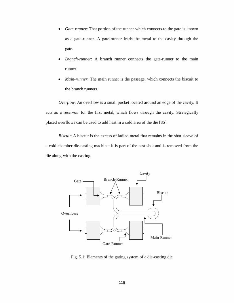
5.1 Elements of the Gating System
Figure 5.1 shows various elements of the gating system of a die-casting die,
which are briefly explained in the following paragraphs.
Gate: It is the entry point for the molten metal to the cavity. Generally, it
provides the smallest restriction in the molten metal flow path to the cavity.
Runner: A runner (or main runner) is the passage that connects the metal
receiving hole of the die to the gate, where the molten metal enters the cavity (or
cavities). A runner can be divided into three sections:
116
Gate-runner: That portion of the runner which connects to the gate is known
as a gate-runner. A gate-runner leads the metal to the cavity through the
gate.
Branch-runner: A branch runner connects the gate-runner to the main
runner.
Main-runner: The main runner is the passage, which connects the biscuit to
the branch runners.
Overflow: An overflow is a small pocket located around an edge of the cavity. It
acts as a reservoir for the first metal, which flows through the cavity. Strategically
placed overflows can be used to add heat in a cold area of the die [85].
Biscuit: A biscuit is the excess of ladled metal that remains in the shot sleeve of
a cold chamber die-casting machine. It is part of the cast shot and is removed from the
die along-with the casting.
Fig. 5.1: Elements of the gating system of a die-casting die
Biscuit
Cavity
Main-Runner
Overflows
Gate-Runner
Branch-Runner Gate
117
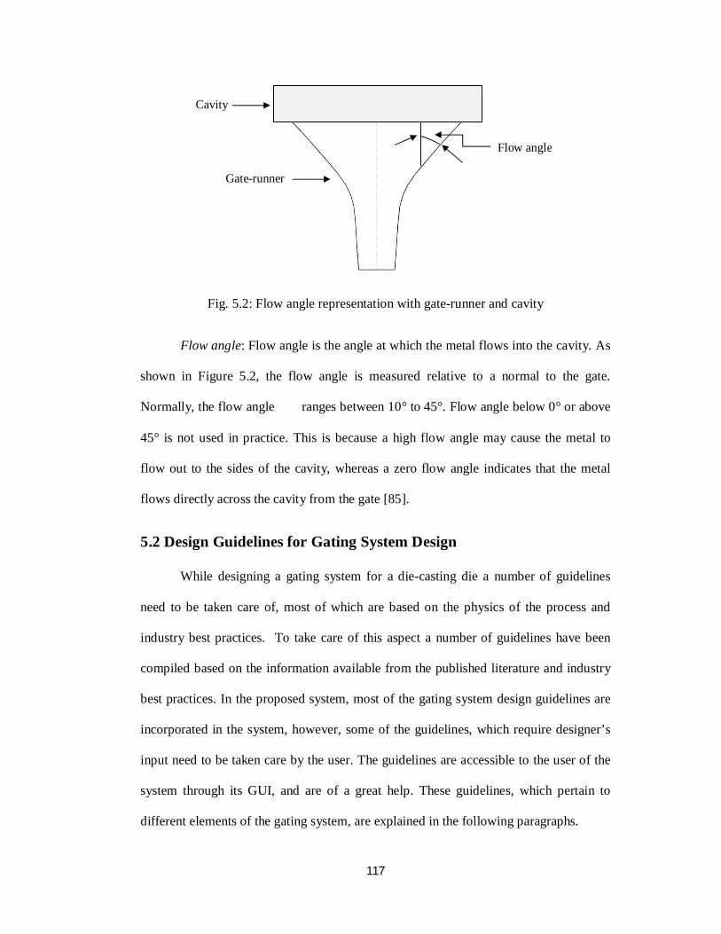
Fig. 5.2: Flow angle representation with gate-runner and cavity
Flow angle: Flow angle is the angle at which the metal flows into the cavity. As
shown in Figure 5.2, the flow angle is measured relative to a normal to the gate.
Normally, the flow angle ranges between 10° to 45°. Flow angle below 0° or above
45° is not used in practice. This is because a high flow angle may cause the metal to
flow out to the sides of the cavity, whereas a zero flow angle indicates that the metal
flows directly across the cavity from the gate [85].
5.2 Design Guidelines for Gating System Design
While designing a gating system for a die-casting die a number of guidelines
need to be taken care of, most of which are based on the physics of the process and
industry best practices. To take care of this aspect a number of guidelines have been
compiled based on the information available from the published literature and industry
best practices. In the proposed system, most of the gating system design guidelines are
incorporated in the system, however, some of the guidelines, which require designer’s
input need to be taken care by the user. The guidelines are accessible to the user of the
system through its GUI, and are of a great help. These guidelines, which pertain to
different elements of the gating system, are explained in the following paragraphs.
Cavity
Gate-runner
Flow angle
118
5.2.1 Gate design
i. The gate should be placed along the shortest cavity dimension, which
reduces metal flow distance.
ii. The gate should be so placed to use the natural part shape to direct the metal
flow. In some cases this may be an exception to the guideline (i) mentioned
above for choosing the shortest flow distance.
iii. For round and oval shape cavity, the gate should be placed at such a location
that central portion of the cavity be filled first.
iv. If possible that area of the part, which has special quality requirements, such
as surface finish or porosity should receive direct flow, and be close to the
gate.
v. The gates should be placed along the thickest section of the part.
vi. If possible, the gate should be directed away from any projections4 that exist
in the cavity.
vii. In a multi-cavity die, where the cavities are identical, gate all of them in the
same manner.
viii. Gate height should not exceed 75% of the wall thickness of the part, which
helps in trimming without distortion or break-out of the part.
ix. Ratio of the gate width to the gate height should be more than 10.
5.2.2 Runner design
i. The cross-sectional area of the runner must be larger than that of the gate to
ensure an increase of flow velocity along the flow path. This reduction in
area should be smooth.
4 These projections may be due to a boss or hole feature of the part, which may requires a projection (negative impression of the feature) in the cavity.
119
ii. For a multi-cavity die, the cross-section area of the main runner should be
larger than the sum of the cross-section area of all branch-runners.
iii. The runner should always be joined with smooth bends to minimize
turbulence and pressure losses.
iv. Going upstream from the branch-runner to the main runner, increase the
runner cross-sectional area by 3% to 5% at every bend, and 3% to 10% at a
‘Y’ junction.
v. In general the flow angle varies between 10° to 45°, however flow angle of
30° is most commonly used.
vi. If possible, the runner should be kept straight for half an inch just before
connecting with the gate-runner.
5.2.3 Overflow design
i. Overflow should be placed either at a point where the metal flow reaches
last or at a point where two flows meet.
ii. It is always better to have many modest overflows than a few large ones for
the purpose of distributed flow within the part.
iii. The sum of out-gate5 cross-sectional areas should be approximately one half
of all in-gate6 cross-sectional areas.
5.2.4 Biscuit design
i. The cross-sectional area of the biscuit must be greater than the cross-
sectional area of the runner.
ii. Minimum recommended thickness for biscuit is 20 mm.
iii. The biscuit should be of at least the same thickness as the runner height.
5 Out-gate cross-sectional area is the area of the metal’s entry to the overflow(s) 6 In-gate cross-sectional area is the area of the gate
120
5.3 Design of Gating System Parameters
In this section the steps of the design of gating system elements are discussed.
The determination of gating system parameters first requires determination of
parameters for filling the hot metal/alloy to the cavity, such as cavity fill time, pressure
and flow velocity. Therefore the following paragraphs discuss cavity fill time, P-Q2
analysis, and gate velocity. The determination of parameters of the gating system
elements, namely gate, runner, overflow and biscuit is discussed thereafter.
5.3.1 Determination of cavity fill parameters
5.3.1.1 Cavity fill time (풕)
Cavity fill time is the time required to completely fill the cavity and overflow
wells. One of the well-known formulas used by the industry to calculate fill time for a
given die-cast part is mentioned in Equation 5.1 [94].
푡 = 퐾 푇 (5.1)
where, 푡 = maximum fill time, sec; 퐾 = empirically derived constant related to
the die steel, s/mm; 푇 = metal temperature at the gate, °C; 푇 = minimum flow
temperature of the metal alloy, °C; 푇 = die surface temperature just before the shot, °C;
푇 = wall thickness of the die-cast part, mm; 푆 = percent solids at the end of fill, %; 푍 =
solid’s unit conversion factor, °C/%.
5.3.1.2 P-Q2 analysis
The P-Q2 analysis, which takes into consideration both the die-casting machine
and the die characteristics, helps to evaluate the performance of the die viz.-a-viz. the
selected machine. Here, it is worth mentioning that the die-casting machine is selected
using the algorithm presented in Chapter 3. The machine’s characteristic curve
121
describes how much pressure (푃 ) the machine applies to the metal at a given flow rate
(Q) [71]. The value of metal pressure (푃 ) can be calculated using Equation 5.2 after
selecting the gate velocity [94]. The gate velocity is selected by the system from the
database taking into account the information of die-cast part material and part
application.
푃 = 푥 (5.2)
where, 푃 = metal pressure, Pa; 휌 = metal density, kg/m3; 푔 = gravitational
constant, m/s2; 푣 = gate velocity, m/s; C = coefficient of discharge [0.45 – 0.5].
The metal pressure creates a breaking force, 퐹, which is proportional to the
projected area of the cavity, 퐴, and is found using Equation 5.3.
퐹 = 푃 × 퐴 (5.3)
The breaking force should be less than the machine tonnage capacity (clamping
force) and in such a case; the system displays the message of “P-Q2 check is OK”. In
case the machine does not pass the P-Q2 check, a die-casting machine with a higher
capacity need to be selected from the machine database, which also requires modified
cavity layout design; the cavity layout design has already been discussed in Chapter 3.
5.3.1.3 Gate velocity
The gate velocity influences the mechanical properties and surface quality of a
die-cast part. Higher gate velocity produces better mechanical properties and less
porosity. New die-casting machines are capable of producing gate velocities up to 100
m/s. However, die erosion starts to increase when the gate velocity reaches 40 m/s; due
to this reason, in normal practice, a gate velocity higher than 40 m/s is not used [94].
122
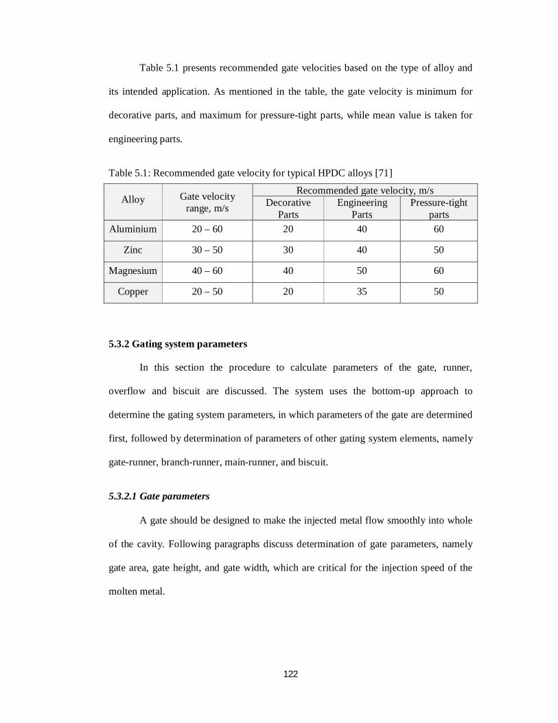
Table 5.1 presents recommended gate velocities based on the type of alloy and
its intended application. As mentioned in the table, the gate velocity is minimum for
decorative parts, and maximum for pressure-tight parts, while mean value is taken for
engineering parts.
Table 5.1: Recommended gate velocity for typical HPDC alloys [71]
Alloy Gate velocity range, m/s
Recommended gate velocity, m/s Decorative
Parts Engineering
Parts Pressure-tight
parts Aluminium 20 – 60 20 40 60
Zinc 30 – 50 30 40 50
Magnesium 40 – 60 40 50 60
Copper 20 – 50 20 35 50
5.3.2 Gating system parameters
In this section the procedure to calculate parameters of the gate, runner,
overflow and biscuit are discussed. The system uses the bottom-up approach to
determine the gating system parameters, in which parameters of the gate are determined
first, followed by determination of parameters of other gating system elements, namely
gate-runner, branch-runner, main-runner, and biscuit.
5.3.2.1 Gate parameters
A gate should be designed to make the injected metal flow smoothly into whole
of the cavity. Following paragraphs discuss determination of gate parameters, namely
gate area, gate height, and gate width, which are critical for the injection speed of the
molten metal.
123
Gate area
The gate area represents the cross-sectional area of a gate and is determined
using Equation 5.4. [94]
퐴 =
(5.4)
where, 퐴 = gate area, mm2; 푉 = part volume, mm3; 푉 = overflows
volume, mm3; 푣 = gate velocity, m/s; 푡 = cavity fill time, sec.
The procedure to determine overflows volume (푉 ) is discussed in the Section
5.3.2.3.
In case of a multi-cavity die the amount of metal flowing through all the gates is
same as all the cavities are identical. The gate area for each cavity of a multi-cavity die
is also determined using Equation 5.4.
In some cases a cavity may be provided with multiple gates to satisfy its metal
filling requirements, in such situations, the gate area determined using Equation 5.4 is
divided by the number of gates of the cavity to find cross-sectional area of each gate.
However, the present system cannot handle multiple gates for a cavity.
Gate height and width
The gate height depends on the selected gate velocity and alloy density, and is
found using Equation 5.5 [94].
푣 . ∗ 퐻 ∗ 휌 ≥ 퐽 (5.5)
where; 퐻 = gate height (mm); 휌 = alloy density (kg/m3); 퐽 =constant, 998000
for aluminium, magnesium and zinc alloys.
124
Equation 5.5 provides minimum value of gate height. However, the user can
interactively choose another suitable value of gate height that fulfils the gating
requirements, in which case the gate width is modified and displayed to the user
through the GUI. The developed system takes care of gate design guidelines (viii and
ix), presented in Section 5.2.1, for selecting suitable value of gate height. Typical gate
height is 0.7 – 3 mm for aluminium alloys, 0.7 – 2.2 mm for magnesium alloys, 0.35 –
1.2 mm for zinc alloys, and from 1.5 – 4 mm for brass alloys.
5.3.2.2 Runner parameters
The function of a runner is to deliver the metal to the gate and to generate the
desired flow pattern within the cavity. The ratio of the runner area (Ar) to gate area
varies with the part design, which usually ranges between 1.1 and 1.4. However, a
larger ratio of 1.6 is used in the case of small parts [94]. The system takes runner area as
1.4 times of gate area by default.
Mostly, trapezoid and round cross-section shapes are used in the runners. For
trapezoid shape runners, the height (Hr) is calculated using Equation 5.6 [94]. The
runner width (Wr) is taken as twice of the runner height.
Hr = .
~ (5.6)
For round shaped runner, the diameter (D) is calculated using Equation. 5.7.
D = × (5.7)
The area of a branch-runner is determined considering the cross-sectional areas
of all the gate-runner to which it feeds the molten metal. Equations 5.6 and 5.7 are also
125
used to determine the cross-sectional area of a branch runner. The system takes care of
the for runner design guidelines (ii and iv) to determine parameters of the main-runner
and branch-runner.
5.3.2.3 Overflow parameters
An overflow collects the initial contaminated metal that traverses the cavity,
provides local heat to the far side of the cavity, and acts as a base for ejecting the
casting from the die. The size and number of overflows depend upon the wall thickness,
surface finish requirements and geometry of the part.
The overflow volume is required to determine width and height of inlet (also
called out-gate area as mentioned in Section 5.2) area of an overflow. The overflow
volume depends upon the factors of volume, wall thickness, shape, and surface finish
requirement of the part [94]. Table 5.2 provides a decision matrix to determine
overflow volume that considers above mentioned factors.
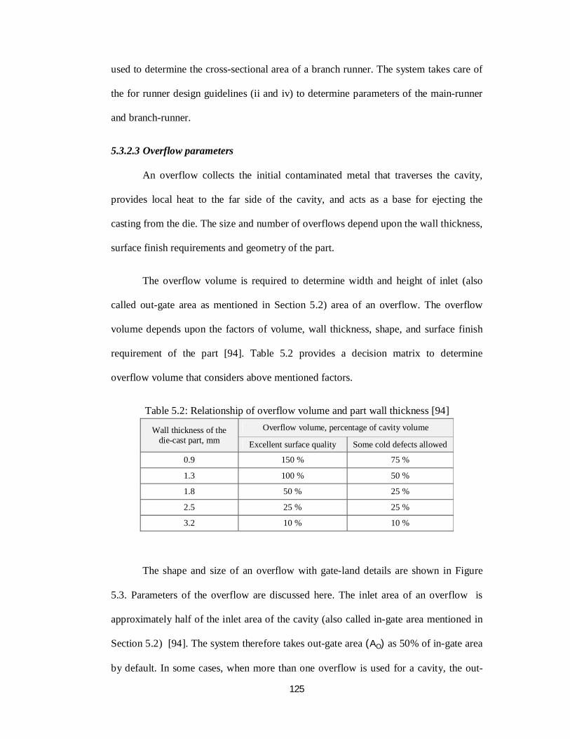
Table 5.2: Relationship of overflow volume and part wall thickness [94]
Wall thickness of the die-cast part, mm
Overflow volume, percentage of cavity volume
Excellent surface quality Some cold defects allowed
0.9 150 % 75 %
1.3 100 % 50 %
1.8 50 % 25 %
2.5 25 % 25 %
3.2 10 % 10 %
The shape and size of an overflow with gate-land details are shown in Figure
5.3. Parameters of the overflow are discussed here. The inlet area of an overflow is
approximately half of the inlet area of the cavity (also called in-gate area mentioned in
Section 5.2) [94]. The system therefore takes out-gate area (AO) as 50% of in-gate area
by default. In some cases, when more than one overflow is used for a cavity, the out-
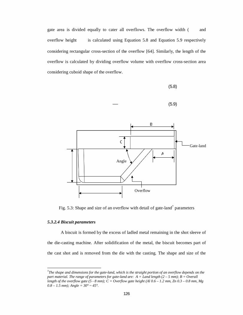
126
gate area is divided equally to cater all overflows. The overflow width ( and
overflow height is calculated using Equation 5.8 and Equation 5.9 respectively
considering rectangular cross-section of the overflow [64]. Similarly, the length of the
overflow is calculated by dividing overflow volume with overflow cross-section area
considering cuboid shape of the overflow.
(5.8)
(5.9)
Fig. 5.3: Shape and size of an overflow with detail of gate-land7 parameters
5.3.2.4 Biscuit parameters
A biscuit is formed by the excess of ladled metal remaining in the shot sleeve of
the die-casting machine. After solidification of the metal, the biscuit becomes part of
the cast shot and is removed from the die with the casting. The shape and size of the
7The shape and dimensions for the gate-land, which is the straight portion of an overflow depends on the part material. The range of parameters for gate-land are: A = Land length (2 – 5 mm); B = Overall length of the overflow gate (5 ‐ 8 mm); C = Overflow gate height (Al 0.6 – 1.2 mm, Zn 0.3 – 0.8 mm, Mg 0.8 – 1.5 mm); Angle = 30° ~ 45°.
C
A
B
Angle
Gate-land
Overflow
127
biscuit depends on the plunger of the die-casting machine. The diameter of the biscuit is
always equal to the plunger diameter and is taken by system from the machine database.
A minimum value of 20 mm is recommended for biscuit thickness.
5.4 Generating CAD models of the Gating System Elements
In this section the methodology for generating CAD models of the gating system
elements are discussed. For generating CAD models of the gating system elements,
selection of the type of gate-runner and main runner is required. In the following
paragraphs, selection of the type of gate-runner and main runner is discussed followed
by a discussion on CAD model generation of the gating system elements.
5.4.1 Selection of a type of gate-runner and main runner
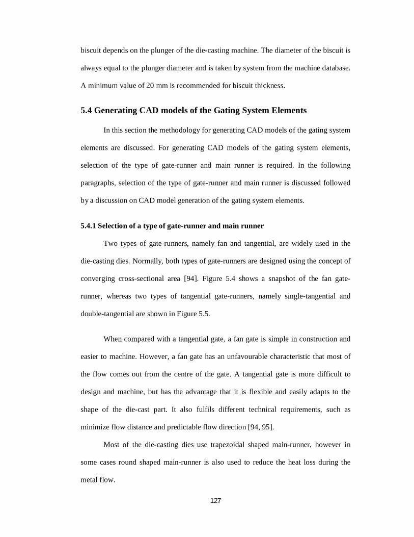
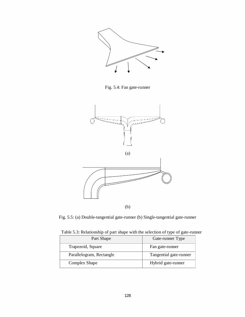
Two types of gate-runners, namely fan and tangential, are widely used in the
die-casting dies. Normally, both types of gate-runners are designed using the concept of
converging cross-sectional area [94]. Figure 5.4 shows a snapshot of the fan gate-
runner, whereas two types of tangential gate-runners, namely single-tangential and
double-tangential are shown in Figure 5.5.
When compared with a tangential gate, a fan gate is simple in construction and
easier to machine. However, a fan gate has an unfavourable characteristic that most of
the flow comes out from the centre of the gate. A tangential gate is more difficult to
design and machine, but has the advantage that it is flexible and easily adapts to the
shape of the die-cast part. It also fulfils different technical requirements, such as
minimize flow distance and predictable flow direction [94, 95].
Most of the die-casting dies use trapezoidal shaped main-runner, however in
some cases round shaped main-runner is also used to reduce the heat loss during the
metal flow.
128
Fig. 5.4: Fan gate-runner
(a)
(b)
Fig. 5.5: (a) Double-tangential gate-runner (b) Single-tangential gate-runner
Table 5.3: Relationship of part shape with the selection of type of gate-runner Part Shape Gate-runner Type
Trapezoid, Square Fan gate-runner
Parallelogram, Rectangle Tangential gate-runner
Complex Shape Hybrid gate-runner
129
The type of gate-runner is selected taking into account the factors of part shape
and geometry; Table 5.3 shows the relationship of part shape with the selection of type
of gate-runner. Generally, a fan gate-runner is recommended when the length to width
ratio of a cavity is close to one, which needs a central fill pattern. Tangential gate-
runner is used when the length to width ratio of a cavity is 1.5 or more, which needs
uniform flow pattern over entire length of the die-cast part. A double-tangential gate-
runner is generally used to feed symmetrical or near symmetrical parts. Hybrid gate-
runner, which is a combination of fan and tangential gate-runner, is also used for
complex shape die-cast parts to fulfil metal flow requirements. The system helps the
user to select suitable gate and runner by displaying above mentioned criteria to the
user. The user input, such as flow angle of gate-runner is used to determine its length.
The length of the gate-runner is further used for generating its CAD model that is
discussed in the next section.
5.4.2 CAD model generation of gating system elements
This section presents the methodology to generate CAD models of the gating
system elements, namely gate-runner, main runner, overflow and biscuit.
5.4.2.1Gate-runner
As discussed in Section 5.1, a gate-runner is the channel or blended portion of a
gating system, which connects the gate with the runner. Generating CAD model of the
gate-runner is a crucial step both for design of the gating system, and manufacturing of
the die. In Section 5.3, the determination of gate and runner parameters is discussed, the
next step is to use these parameters to generate CAD model of the gate-runner by taking
flow angle as input. Following paragraphs discuss CAD model generation of two types
of gate-runners, namely fan and tangential.
130
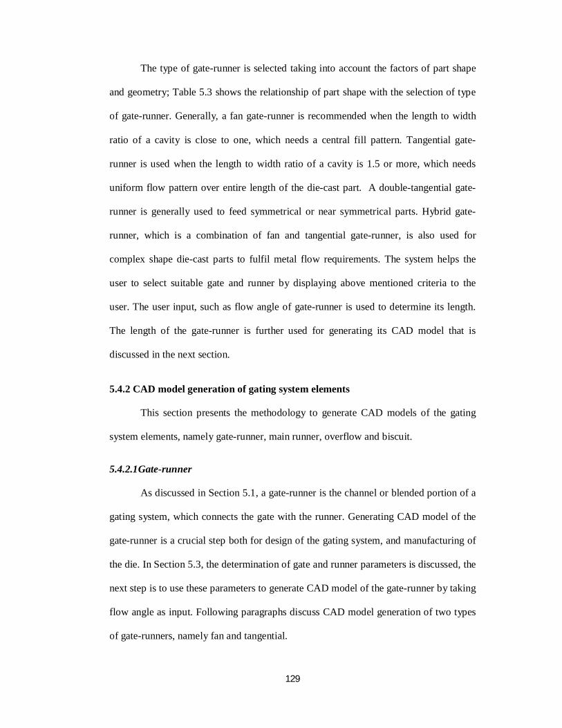
Fan gate-runner
Fig. 5.6: CAD model of a gate-runner with the cross-sectional profiles
Figure 5.6 shows CAD model of a gate-runner with various transitions in the
cross-sections between the gate and runner sides. North American Die Casting
Association recommends nine section profiles to get desired gate-runner but use of five
section profiles is also quite common in the industry. The developed system uses five
section profiles to generate CAD model of a fan gate-runner using the formulas given in
Table 5.4 [34, 71]. The profile of a gate-runner here means the determination of height
and width at each section.
Table 5.4: Determination of gate-runner cross-sectional profiles
Section No. Height Width 1 [runner side] = /
2 = + 3/4 ( – ) = [ + 3/4 ( – )] /
3 = + 1/2 ( – ) = [ + 1/2 ( – )] /
4 = + 1/4 ( – ) = [ + 1/4 ( – )] /
5[gate side] = / Wg
Gate Side
Runner Side
Sec -5
Sec -4
Sec -3
Sec -2
Sec -1
Length of gate-runner
131
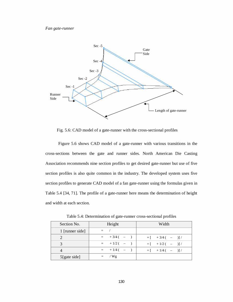
where, 퐴 = gate area, mm2;퐻 = gate height, mm; 푊 = gate width, mm;퐴 =
runner area, mm2;퐻 = runner height, mm; 푊 = runner width, mm; 퐻 ,퐻 ,퐻 and
푊 ,푊 ,푊 are height and width of section profile at respective section, mm.
The length of the gate-runner is determined using Equation 5.10.
Lenght of gate− runner =
× (5.10)
The information about sectional profiles and length of the gate is used to
generate its CAD model using specific gate-runner feature from the pre-defined feature
library.
Tangential gate-runner
A tangential gate-runner is tapered towards the ends, connects tangentially to the
part, and has a width equal to the full length of the part. A tangential gate-runner may
be curved, straight or bent, and ideally located on the longest side of the part. It is also
recommended that a tapered gate-runner be extended to provide a “shock absorber” to
absorb the excess of kinetic energy, which otherwise may create localized die erosion.
The shock absorber is a tangential channel whose diameter approximates the square
root of the inlet area. Figure 5.7 shows a tangential gate-runner with the shock absorber.
Because of the flow angle, the effective gate area is smaller than the actual gate
area in tangential gate-runner, and is found using Equation 5.11. The gate-runner cross-
section converges towards the gate borders because of the flow angle (as shown in
Figure 5.7).
cos(φ) =
(5.11)
132
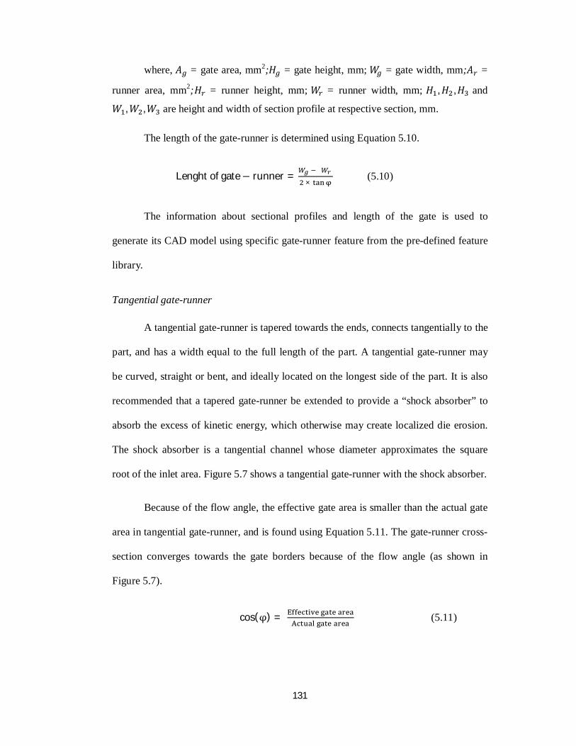
Fig. 5.7: Effective and actual gate area for tangential gate-runner
Fig. 5.8: Cross-sectional profile for tangential gate-runner
The cross-sectional profile of a tangential gate-runner is shown in Figure 5.8.
Parameters of the cross-sectional area of the tangential gate are approach angle, back
wall draft angle, height, moderate width8, and aspect ratio9. Typical approach and back
wall draft angles are 30° and 80° respectively, and typical aspect ratio is 2. The
parameters of cross-sectional profiles are generated using the equations given in Table
8 The moderate width is the width in the middle of the profile. 9 The aspect ratio is the ratio of the moderate width to the height of the gate-runner.
Actual gate area
Effective gate area
Shock absorber
α = Back wall draft angleβ = Approach angle
Moderate Width, w
Height, h
133
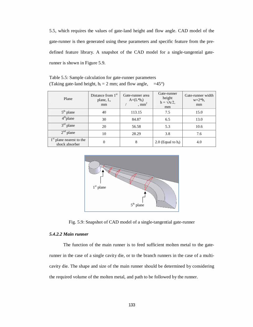
5.5, which requires the values of gate-land height and flow angle. CAD model of the
gate-runner is then generated using these parameters and specific feature from the pre-
defined feature library. A snapshot of the CAD model for a single-tangential gate-
runner is shown in Figure 5.9.
Table 5.5: Sample calculation for gate-runner parameters (Taking gate-land height, hl = 2 mm; and flow angle, =45°)
Plane Distance from 1st
plane, L, mm
Gate-runner area A=(L*hl)
/ , mm2
Gate-runner height
h = √A/2, mm
Gate-runner width w=2*h,
mm
5th plane 40 113.15 7.5 15.0 4thplane 30 84.87 6.5 13.0 3rd plane 20 56.58 5.3 10.6 2nd plane 10 28.29 3.8 7.6
1st plane nearest to the shock absorber 0 8 2.0 (Equal to hl) 4.0
Fig. 5.9: Snapshot of CAD model of a single-tangential gate-runner
5.4.2.2 Main runner
The function of the main runner is to feed sufficient molten metal to the gate-
runner in the case of a single cavity die, or to the branch runners in the case of a multi-
cavity die. The shape and size of the main runner should be determined by considering
the required volume of the molten metal, and path to be followed by the runner.
1st plane
5th plane
134
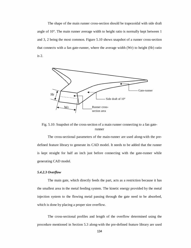
The shape of the main runner cross-section should be trapezoidal with side draft
angle of 10°. The main runner average width to height ratio is normally kept between 1
and 3, 2 being the most common. Figure 5.10 shows snapshot of a runner cross-section
that connects with a fan gate-runner, where the average width (Wr) to height (Hr) ratio
is 2.
Fig. 5.10: Snapshot of the cross-section of a main runner connecting to a fan gate-runner
The cross-sectional parameters of the main-runner are used along-with the pre-
defined feature library to generate its CAD model. It needs to be added that the runner
is kept straight for half an inch just before connecting with the gate-runner while
generating CAD model.
5.4.2.3 Overflow
The main gate, which directly feeds the part, acts as a restriction because it has
the smallest area in the metal feeding system. The kinetic energy provided by the metal
injection system to the flowing metal passing through the gate need to be absorbed,
which is done by placing a proper size overflow.
The cross-sectional profiles and length of the overflow determined using the
procedure mentioned in Section 5.3 along-with the pre-defined feature library are used
Side draft of 10°
Gate-runner
Runner cross-section area
Hr
Wr
135
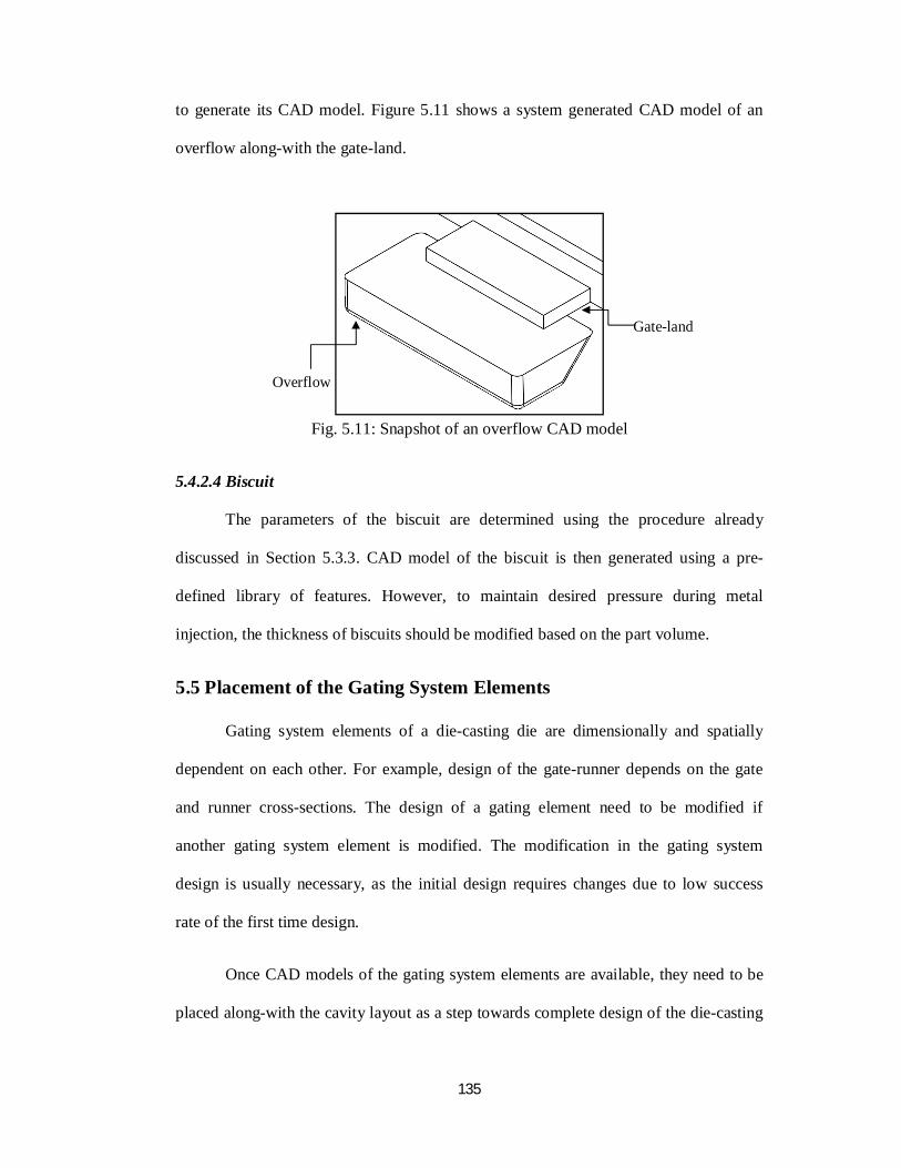
to generate its CAD model. Figure 5.11 shows a system generated CAD model of an
overflow along-with the gate-land.
Fig. 5.11: Snapshot of an overflow CAD model
5.4.2.4 Biscuit
The parameters of the biscuit are determined using the procedure already
discussed in Section 5.3.3. CAD model of the biscuit is then generated using a pre-
defined library of features. However, to maintain desired pressure during metal
injection, the thickness of biscuits should be modified based on the part volume.
5.5 Placement of the Gating System Elements
Gating system elements of a die-casting die are dimensionally and spatially
dependent on each other. For example, design of the gate-runner depends on the gate
and runner cross-sections. The design of a gating element need to be modified if
another gating system element is modified. The modification in the gating system
design is usually necessary, as the initial design requires changes due to low success
rate of the first time design.
Once CAD models of the gating system elements are available, they need to be
placed along-with the cavity layout as a step towards complete design of the die-casting
Gate-land
Overflow
136
die. This section discusses the steps to place the gating system elements in a multi-
cavity die.
Step 1 - Cavity layout: Cavity layout design is one of the basic requirements to
place the gating system elements in the cavity. The cavity layout design in case of a
multi-cavity die includes activities, such as determine the number of cavities, orient the
cavities, and place the cavities in a die-base with required clearances. All these
activities depend upon a number of factors influenced by the part design, material, and
the die-casting machine. The algorithms of cavity layout design, which are used in the
developed system, have been presented in Chapter 3.
Step 2 - Determination of possible gate location: After cavity layout is decided,
the candidate sides for the gate location are determined. For this, all the possible
alternatives are shortlisted and the best option is chosen by the designer. Although the
system for cavity layout design takes care of the undercut position, a number of factors
need to be considered for choosing the best option, such as surface finish requirement
and type of feeding system.
Step 3 - Assemble CAD models of gating system elements: Assembly of CAD
models of the gating system elements are explained in the following steps.
i. The gate-runners are placed at the selected locations of the part model.
ii. The main runner and branch runners are assembled with the gate-runner
using Boolean operations.
iii. CAD model of the biscuit is assembled with the main runner to complete the
gating channel.
iv. The overflows are placed at the selected location using Boolean operations.
137
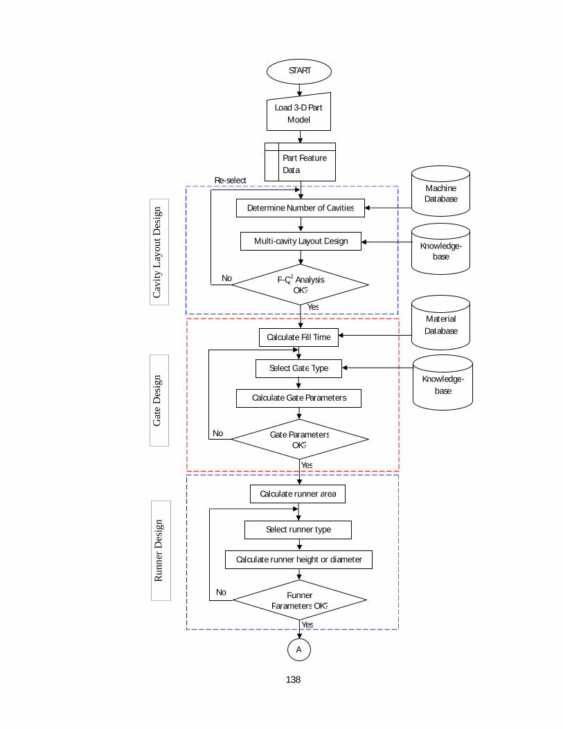
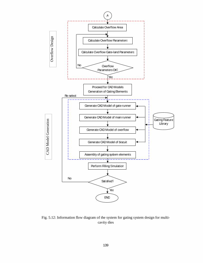
5.6 System Architecture
This section discusses the architecture of the system for gating system design for
multi-cavity dies. The information flow diagram of the proposed system for gating
system design for multi-cavity dies is presented in Figure. 5.12. Following paragraphs
describe steps of the proposed system.
i. Load CAD file of the die-cast part, which is used to extract part information.
ii. Determine number of cavities and display the cavity layout design.
iii. The P-Q2 check is performed for checking the suitability of the selected die-
casting machine. The system shows the message of “P-Q2 check is OK” or
prompts the user to change the machine.
iv. Gate parameters are determined using various factors, such as the number of
cavities, material information, part application type, cavity volume, and wall
thickness of die-cat part. The gate parameters are verified with the industry
recommendations given in Appendix-I; however the user is allowed to change
these parameters as per his/her preference.
v. Runner and overflow parameters are determined. These parameters are also
evaluated against the recommended values.
vi. If the gating parameters are within the permissible range, and acceptable to the
user, he/she may proceed further to generate the gating system elements.
vii. CAD models of the gating system elements, namely gate-runner, main runner,
overflow, and biscuit are generated using their parameters and library of
features.
viii. CAD models of the gating system elements are assembled using SolidWorks
assembly work-bench using Boolean operations to generate CAD model of
gating system for a given cavity layout pattern.
138
Cav
ity L
ayou
t Des
ign
Gat
e D
esig
n R
unne
r Des
ign
Yes
Calculate Fill Time
Select Gate Type
Calculate Gate Parameters
Gate Parameters OK?
Knowledge-base
Material Database
No
Yes
No
Calculate runner area
Select runner type
Calculate runner height or diameter
Runner Parameters OK?
A
Yes
Part Feature Data
Determine Number of Cavities
Machine Database
Multi-cavity Layout Design Knowledge-base
P-Q2 Analysis OK?
Load 3-D Part Model
No
START
Re-select
139
Fig. 5.12: Information flow diagram of the system for gating system design for multi-cavity dies
Ove
rflo
w D
esig
n C
AD
Mod
el G
ener
atio
n
Re-select
Gating Feature Library
Yes
Generate CAD Model of gate-runner
Generate CAD Model of main runner
Generate CAD Model of overflow
Generate CAD Model of biscuit
Assembly of gating system elements
Perform Filling Simulation
Satisfied? No
END
Proceed for CAD Models Generation of Gating Elements
Yes
Calculate Overflow Area
Calculate Overflow Parameters
Calculate Overflow Gate-land Parameters
Overflow Parameters OK?
No
A

140
ix. Lastly, filling simulation is performed to validate the gating system design and
to make required modifications. The user has the option to either
reselect/modify the gating parameters, or to modify/rebuild CAD models of the
gating system elements for necessary improvements.
5.7 System Implementation and Results
In this section, first, implementation of the proposed system is discussed,
followed by a discussion on results. The results obtained from the system are also
validated using process simulation.
5.7.1 System implementation
The development platform for the system for gating system design for multi-
cavity die-casting dies is SolidWorks CAD software [13] using its API with
programming in Microsoft VB.NET.
The developed system functions as an add-on application of SolidWorks, and
has the advantage of data integration from part design up-to the complete die-design
and manufacturing. Figure 5.12 shows the information flow diagram of the developed
system. Most of the computational tasks that need information about the cavities,
material, etc. are determined with the help of the developed system. The system
provides an option to the user at various steps, either to accept the system recommended
parameter or input another desired value. This aspect of the developed system makes it
more useful in the industrial environment.
5.7.2 Results
The developed system has been tested on parts taken from the die-casting
industry. To demonstrate the capabilities of the developed system, the results of the
case study of a cylinder head cover are presented in the following paragraphs.
141
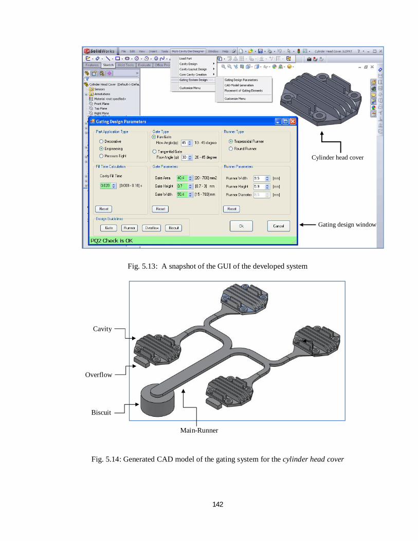
Case study: Cylinder head cover
The die-cast part taken in this case study is an automotive part named cylinder
head cover, which is shown in Figure 5.13. The characteristics of the part are:
aluminium alloy material, no undercut features in the selected parting direction and
envelope size of 82.8 mm x 65.3 mm x 15 mm (Length x Breadth x Height).
The number of cavities determined by system is four and selected layout pattern
is series with bottom feeding system. Figure 5.13 shows a snapshot of the graphic user
interface (GUI) of the developed system in SolidWorks platform. The system first
performs the P-Q2 analysis, which is shown at the bottom of the gating design parameter
window. The part application type is selected as Engineering; gate type is Fan and
runner type is Trapezoidal with flow angle of 45°. The determined filling time is 0.028
sec, gate area is 40.4 mm2 and gate height is 0.7 mm respectively, which is well within
the industry recommended range. The runner parameters determined by the system are
also within the recommended range. The recommended value/range for each of the
gating parameters is also displayed for ready reference of the user. The final CAD
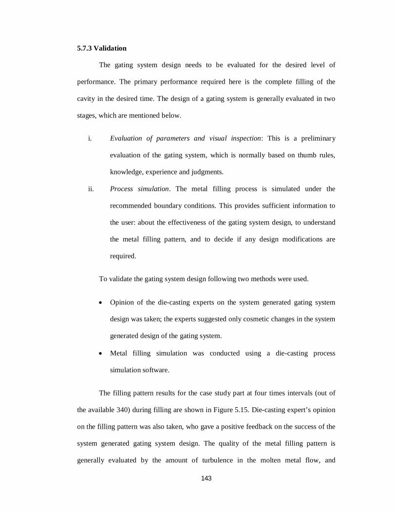
model of the gating system is presented in Figure 5.14.
Discussion
The design of gating system for a die-cast part is an iterative process. Although,
in the developed system, sufficient knowledge is provided to facilitate decision making
at different stages, it may still require alterations/modifications by an experienced user.
To take care of this aspect, enough flexibility is provided in the system for the user to
alter suggested decisions interactively, which makes the system quite useful and
practicable.
142
Fig. 5.13: A snapshot of the GUI of the developed system
Fig. 5.14: Generated CAD model of the gating system for the cylinder head cover
Biscuit
Cavity
Main-Runner
Overflow
Cylinder head cover
Gating design window
143
5.7.3 Validation
The gating system design needs to be evaluated for the desired level of
performance. The primary performance required here is the complete filling of the
cavity in the desired time. The design of a gating system is generally evaluated in two
stages, which are mentioned below.
i. Evaluation of parameters and visual inspection: This is a preliminary
evaluation of the gating system, which is normally based on thumb rules,
knowledge, experience and judgments.
ii. Process simulation. The metal filling process is simulated under the
recommended boundary conditions. This provides sufficient information to
the user: about the effectiveness of the gating system design, to understand
the metal filling pattern, and to decide if any design modifications are
required.
To validate the gating system design following two methods were used.
Opinion of the die-casting experts on the system generated gating system
design was taken; the experts suggested only cosmetic changes in the system
generated design of the gating system.
Metal filling simulation was conducted using a die-casting process
simulation software.
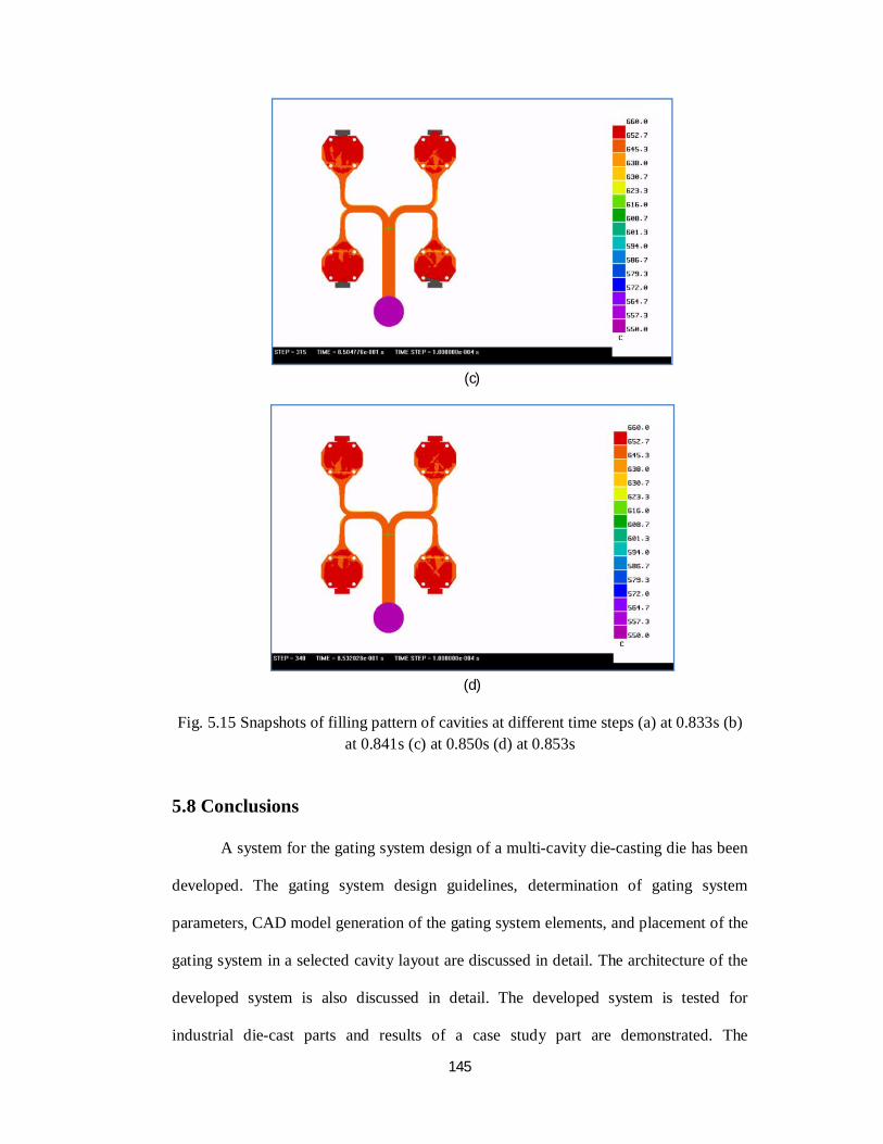
The filling pattern results for the case study part at four times intervals (out of
the available 340) during filling are shown in Figure 5.15. Die-casting expert’s opinion
on the filling pattern was also taken, who gave a positive feedback on the success of the
system generated gating system design. The quality of the metal filling pattern is
generally evaluated by the amount of turbulence in the molten metal flow, and
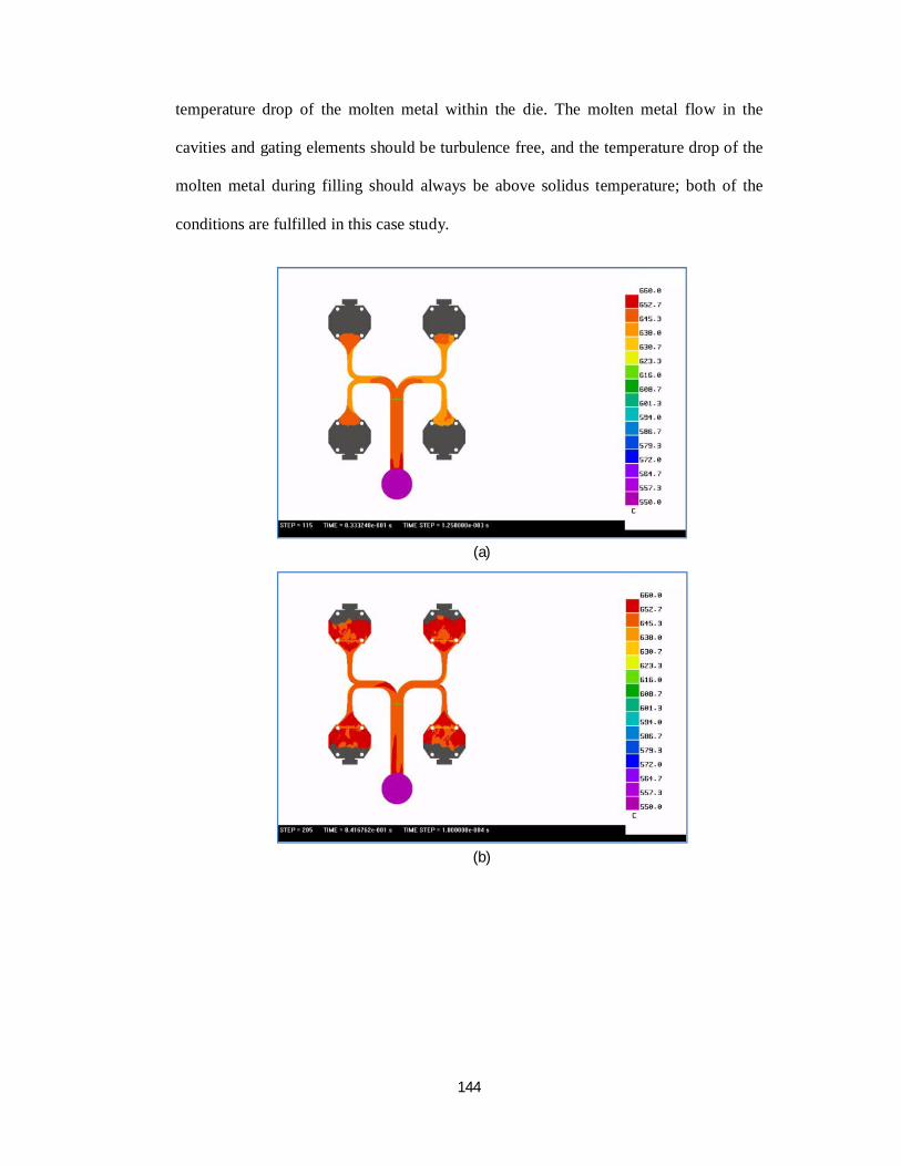
144
temperature drop of the molten metal within the die. The molten metal flow in the
cavities and gating elements should be turbulence free, and the temperature drop of the
molten metal during filling should always be above solidus temperature; both of the
conditions are fulfilled in this case study.
(a)
(b)
145
(c)
(d)
Fig. 5.15 Snapshots of filling pattern of cavities at different time steps (a) at 0.833s (b) at 0.841s (c) at 0.850s (d) at 0.853s
5.8 Conclusions
A system for the gating system design of a multi-cavity die-casting die has been
developed. The gating system design guidelines, determination of gating system
parameters, CAD model generation of the gating system elements, and placement of the
gating system in a selected cavity layout are discussed in detail. The architecture of the
developed system is also discussed in detail. The developed system is tested for
industrial die-cast parts and results of a case study part are demonstrated. The
146
developed system uses SolidWorks part file along-with the user interaction to generate
elements of the gating system for a multi-cavity die-casting die using gating feature
library. The developed system is an effort to integrate die-casting die-design application
into existing CAD software.
The gating system design is central to die-casting technology. There is perhaps
no skill more important to a die-casting die-designer than the ability to design an
effective gating system. The design of gating system for a die-cast part may vary as per
the designer’s experience, die-casting machine limitations, delivery requirements and
cost factors. The developed system blends the die-casting die-design rules and the
industry best practices, along with the flexibility desired by a die-designer in a CAD
system environment, and prove to be an effective tool in the hands of a die-designer.
Furthermore, the system significantly reduces the time required for the design of gating
system, needs little user interaction, and is very much useful for the industry.
Following are the major conclusions drawn from this research work:
The developed system works as an add-on application for gating system design
for multi-cavity die-casting die, for an existing CAD software. Such an
application is much desirable by the die-casting industry since available mold
design applications of CAD systems do not provide such functionality especially
suitable for die-casting process.
The system provides basic design rules and guidelines for ready reference of the
user which are followed by the die-casting industry and die-designers for gating
system design. These rules and guidelines provide step-by-step guideline to the
user for getting first-time success.
147
Determination of gating parameters is generally carried out using empirical
relations and a lot of manual calculations. The gating system design module of
the developed system is capable to determine gating parameters of the given die-
cast part in an automated manner. The system also ensures that determined
gating parameters are within the industry recommended range.
Generation of CAD model of gate-runner, main runner and overflow for a given
die-cast part is complex and time-consuming process. The process requires
manual calculation for determination of different section profiles which are used
to create CAD model to gating elements. The developed system determines
these parameters and generates their CAD model using gating feature library
with little user interaction.
The gating system design needs to be evaluated for the desired level of
performance. The primary performance required here is the complete filling of
the cavity in a desired time. The metal filling simulation of the multi-cavity dies
generated using the developed system is found to be satisfactory, and is
acceptable to the industrial users.