Chapter 3 Part-2 Physical Layer - un.uobasrah.edu.iq
36
9/29/2018 1 Chapter 3 Part-2 Physical Layer Transmission Impairments Prepared By: A/P Dr. Ghaida A. AL-Suhail Computer Engineering Dept.- 3 rd Year CoE331-2015-2016 University of Basrah
Transcript of Chapter 3 Part-2 Physical Layer - un.uobasrah.edu.iq
9/29/2018 1
Chapter 3 Part-2
Physical Layer
Transmission Impairments
Prepared By: A/P Dr. Ghaida A. AL-Suhail Computer Engineering Dept.- 3rd Year CoE331-2015-2016
University of Basrah
9/29/2018 2
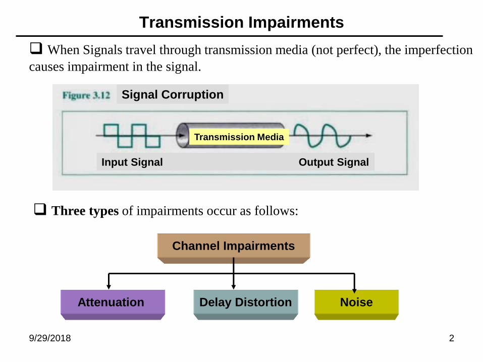
Transmission Impairments
When Signals travel through transmission media (not perfect), the imperfection
causes impairment in the signal.
Three types of impairments occur as follows:
Channel Impairments
Attenuation Delay Distortion Noise
Input Signal Output Signal
Signal Corruption
Transmission Media

9/29/2018 3
1- Attenuation: (Loss of Energy ≡ Reduction in Signal Strength)
When a signal travels through a medium, it loses some of its energy
(because of wire resistance) a wire becomes warm (or hot).
The Strength of Signal falls off with distance leads reduction in signal
strength (attenuation) or called (loss) in dB/m or dB/km in guided media.
Point1 Point2
Original Attenuated Amplified
Point3
Transmission Line
Amplifier
Attenuation
9/29/2018 4
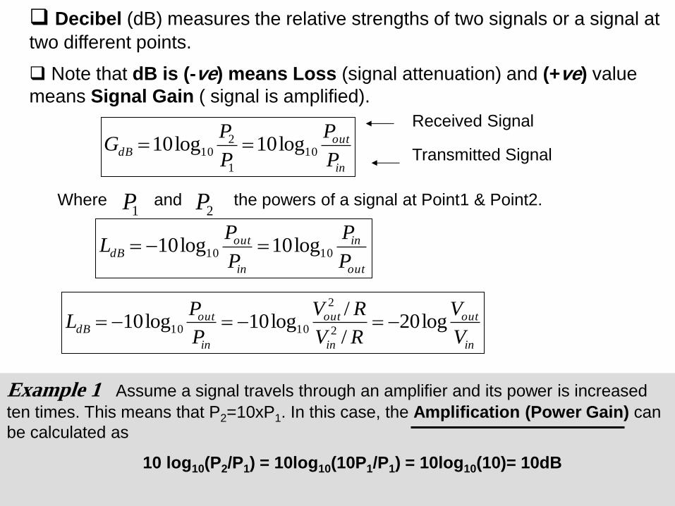
Decibel (dB) measures the relative strengths of two signals or a signal at
two different points.
Note that dB is (-ve) means Loss (signal attenuation) and (+ve) value
means Signal Gain ( signal is amplified).
in
outdB
P
P
P
PG 10
1
210 log10log10
Where and the powers of a signal at Point1 & Point2. 1P 2P
Received Signal
Transmitted Signal
out
in
in
outdB
P
P
P
PL 1010 log10log10
in
out
in
out
in
outdB
V
V
RV
RV
P
PL log20
/
/log10log10
2
2
1010
Example 1 Assume a signal travels through an amplifier and its power is increased
ten times. This means that P2=10xP1. In this case, the Amplification (Power Gain) can
be calculated as
10 log10(P2/P1) = 10log10(10P1/P1) = 10log10(10)= 10dB
9/29/2018 5
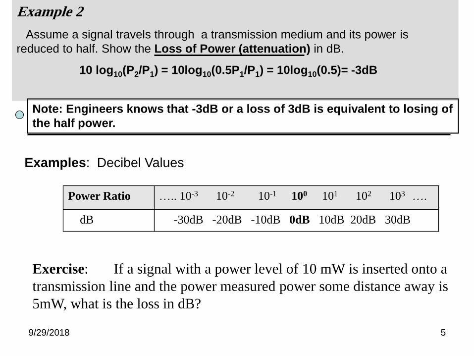
Examples: Decibel Values
Exercise: If a signal with a power level of 10 mW is inserted onto a
transmission line and the power measured power some distance away is
5mW, what is the loss in dB?
Power Ratio ….. 10-3 10-2 10-1 100 101 102 103 ….
dB -30dB -20dB -10dB 0dB 10dB 20dB 30dB
Example 2
Assume a signal travels through a transmission medium and its power is
reduced to half. Show the Loss of Power (attenuation) in dB.
10 log10(P2/P1) = 10log10(0.5P1/P1) = 10log10(0.5)= -3dB
Note: Engineers knows that -3dB or a loss of 3dB is equivalent to losing of
the half power.
9/29/2018 6
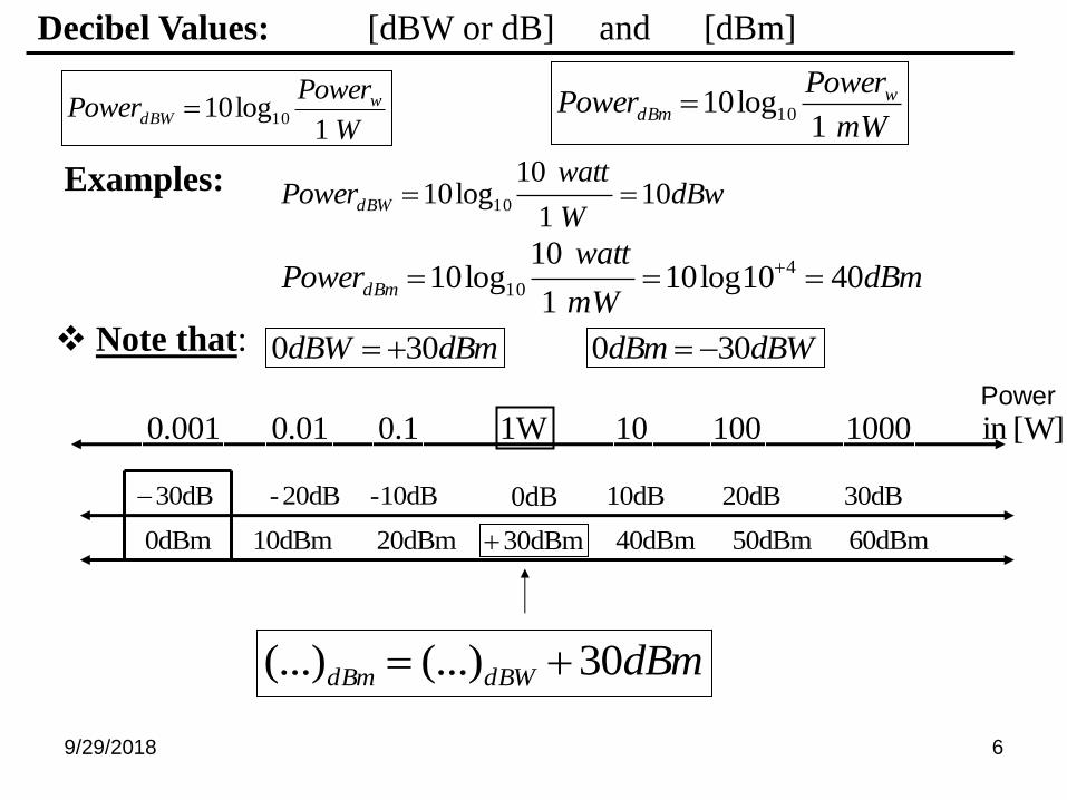
Decibel Values: [dBW or dB] and [dBm]
W
PowerPower w
dBW1
log10 10mW
PowerPower w
dBm1
log10 10
dBwW
wattPowerdBW 10
1
10log10 10 Examples:
dBmmW
wattPowerdBm 4010log10
1
10log10 4
10
dBmdBW 300 dBWdBm 300 Note that:
dB0
dBm30
1W 10 100 1000
30dB 20dB dB10
0.10.010.001 [W]in
10dB- 20dB- dB30
60dBm 50dBm dBm4020dBm 10dBm dBm0
dBmdBWdBm 30(...)(...)
Power
9/29/2018 7
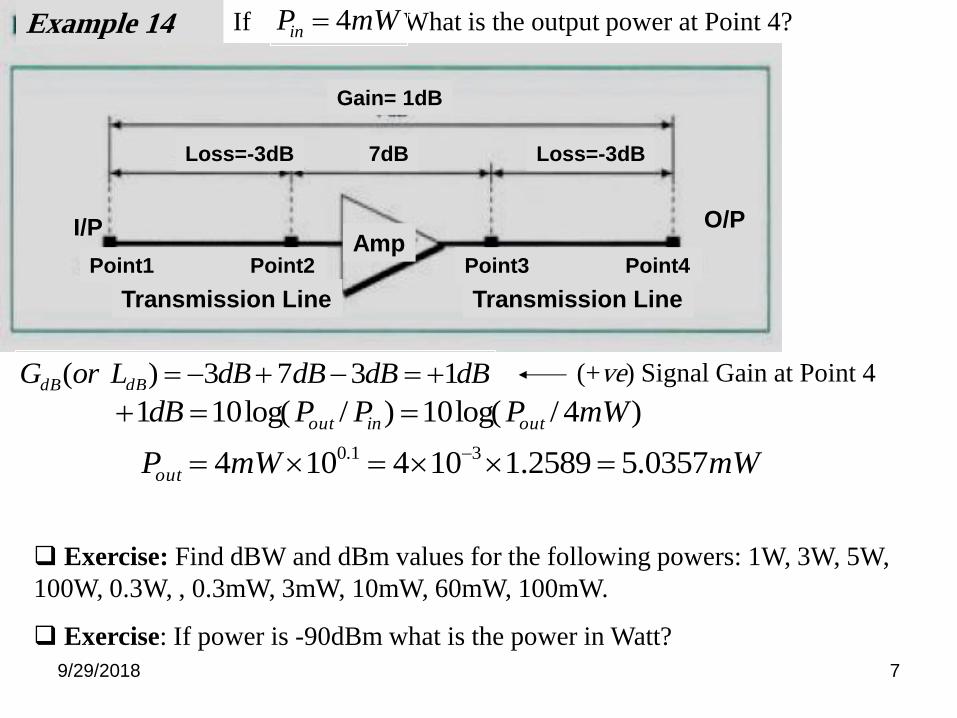
dBdBdBdBLorG dBdB 1373)( (+ve) Signal Gain at Point 4
)4/log(10)/log(101 mWPPPdB outinout
If What is the output power at Point 4? mWPin 4
mWmWPout 0357.52589.1104104 31.0
I/P O/P
Example 14
Point1 Point2
Transmission Line Transmission Line
Point3 Point4
Loss=-3dB Loss=-3dB 7dB
Gain= 1dB
Amp
Exercise: Find dBW and dBm values for the following powers: 1W, 3W, 5W,
100W, 0.3W, , 0.3mW, 3mW, 10mW, 60mW, 100mW.
Exercise: If power is -90dBm what is the power in Watt?

9/29/2018 8
2- Delay Distortion:
Signal changes its shape because of signal propagation speed
For band-limited signal, the velocity is higher near the center frequency
and fall off toward the two end of the band.
cf
Frequency Components arrive at RX at different times
resulting phase shifts between different frequencies
is called Delay Distortion. Solving this problem by
Equalization filter
Composite Signal
Distortion
Transmission
Medium
Components in
phase
Composite Signal
Received
Point1 Point2
Components out
of phase

9/29/2018 9
Equalization Filter: is used to reduce delay distortion.
Example: The attenuation of coaxial cable at frequency of f MHz is given by
A(f) = 11x f 0.6 dB/km
If bits are transmitted in unipolar modulation at rate of R [bps], then max. freq. in
the signal occurs when the bits 0s and 1s alternate. In this case, the signal is
square wave with period T=2/R. Assume R=1Mbps.
Find the attenuation of coaxial cable at different frequency components of the
square wave: f=1/T=R/2, 3f=3/T=3R/2 , 5f=5/T=5R/2…etc
0 T 2T
unipolar
T=2/R
A(f) = 11x (R/2) 0.6 =7 dB/km
A(5f) = 11x (5R/2) 0.6 =19 dB/km
If coaxial cable has a length of 1km, the
two attenuations differ by 12dB.
This range must be compensated by
Equalizer Filter. f 3f 5f frequency
0 1 0 1 …..
R=1Mbps
9/29/2018 10
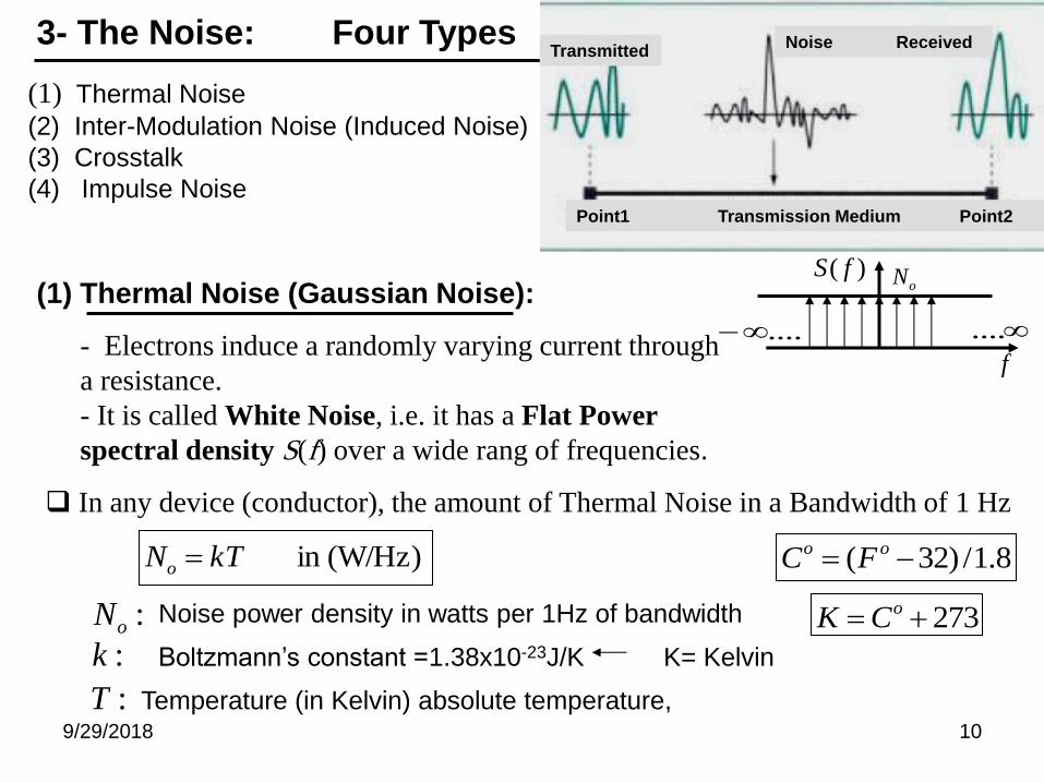
3- The Noise: Four Types
(1) Thermal Noise
(2) Inter-Modulation Noise (Induced Noise)
(3) Crosstalk
(4) Impulse Noise
- Electrons induce a randomly varying current through
a resistance.
- It is called White Noise, i.e. it has a Flat Power
spectral density S(f) over a wide rang of frequencies.
In any device (conductor), the amount of Thermal Noise in a Bandwidth of 1 Hz
(W/Hz)in kTNo
:oN Noise power density in watts per 1Hz of bandwidth
:k Boltzmann’s constant =1.38x10⁻²³J/K
:T Temperature (in Kelvin) absolute temperature,
oN
f
)( fS(1) Thermal Noise (Gaussian Noise):
........
Point1 Transmission Medium Point2
Transmitted Noise Received
K= Kelvin
8.1/)32( oo FC
273 oCK
9/29/2018 11
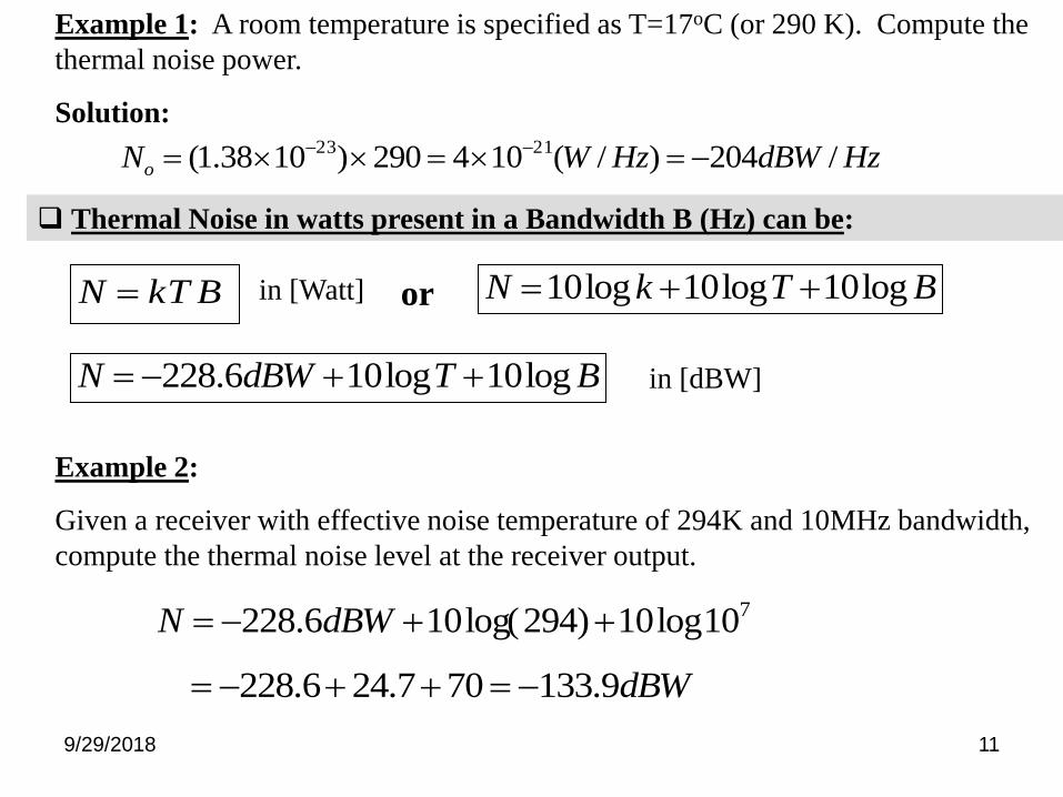
HzdBWHzWNo /204)/(104290)1038.1( 2123
Example 1: A room temperature is specified as T=17oC (or 290 K). Compute the
thermal noise power.
Solution:
Example 2:
Given a receiver with effective noise temperature of 294K and 10MHz bandwidth,
compute the thermal noise level at the receiver output.
Thermal Noise in watts present in a Bandwidth B (Hz) can be:
BkTN or BTkN log10log10log10
BTdBWN log10log106.228
710log10)294log(106.228 dBWN
dBW9.133707.246.228
in [Watt]
in [dBW]
9/29/2018 12
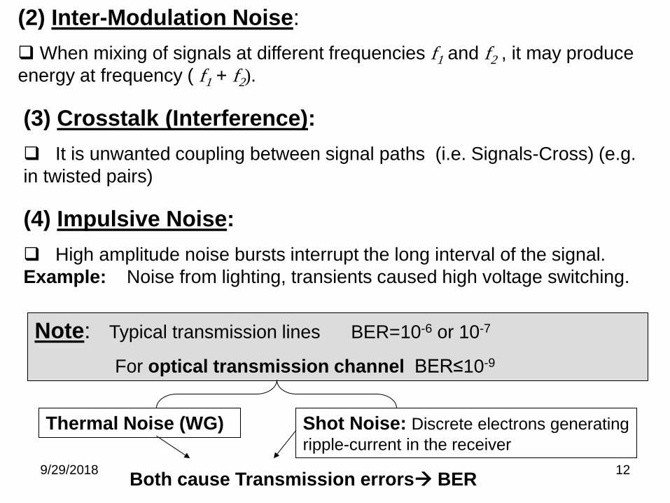
(2) Inter-Modulation Noise:
When mixing of signals at different frequencies f1 and f2 , it may produce
energy at frequency ( f1 + f2).
(3) Crosstalk (Interference):
It is unwanted coupling between signal paths (i.e. Signals-Cross) (e.g.
in twisted pairs)
(4) Impulsive Noise:
High amplitude noise bursts interrupt the long interval of the signal.
Example: Noise from lighting, transients caused high voltage switching.
Note: Typical transmission lines BER=10-6 or 10-7
For optical transmission channel BER≤10-9
Thermal Noise (WG) Shot Noise: Discrete electrons generating
ripple-current in the receiver
Both cause Transmission errors BER
9/29/2018 13
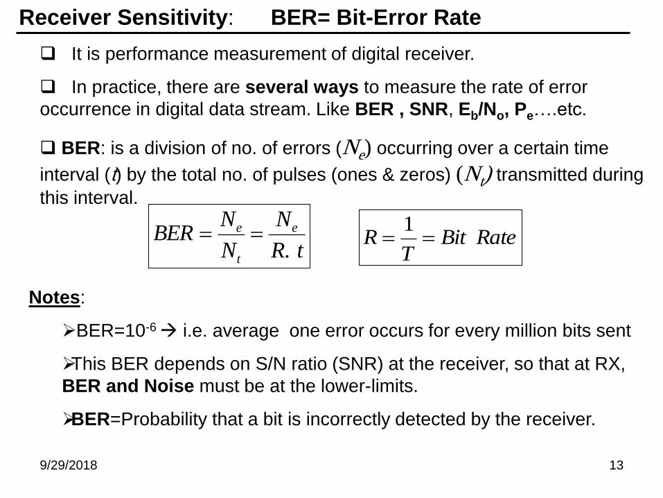
Receiver Sensitivity: BER= Bit-Error Rate
It is performance measurement of digital receiver.
In practice, there are several ways to measure the rate of error
occurrence in digital data stream. Like BER , SNR, Eb/No, Pe….etc.
BER: is a division of no. of errors (Ne) occurring over a certain time
interval (t) by the total no. of pulses (ones & zeros) (Nt) transmitted during
this interval.
tR
N
N
NBER e
t
e
. RateBit
TR
1
Notes:
BER=10-6 i.e. average one error occurs for every million bits sent
This BER depends on S/N ratio (SNR) at the receiver, so that at RX,
BER and Noise must be at the lower-limits.
BER=Probability that a bit is incorrectly detected by the receiver.
9/29/2018 14
0 Level
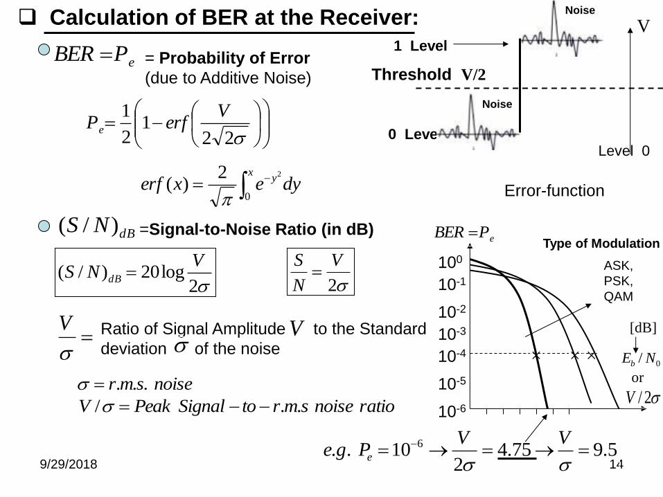
Calculation of BER at the Receiver:
Threshold V/2
1 Level
Level 0
V
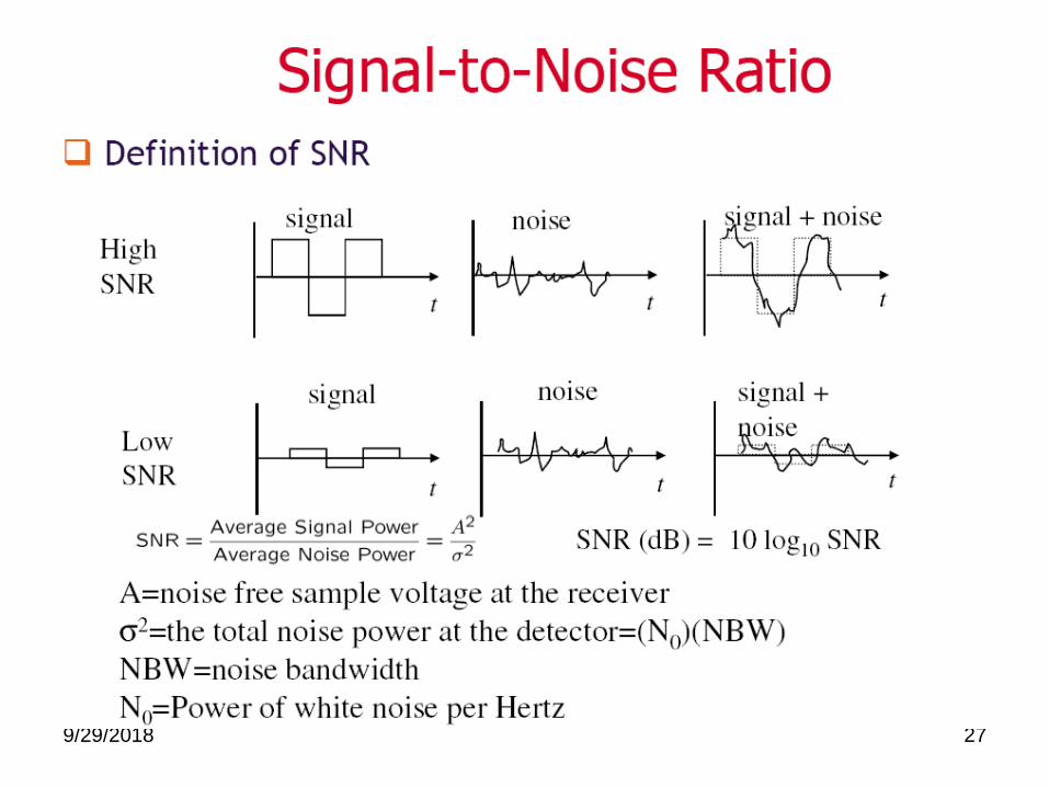
= Probability of Error
(due to Additive Noise) ePBER
221
2
1 VerfPe
xy dyexerf
0
22)(
Error-function
2log20)/(
VNS dB
dBNS )/( =Signal-to-Noise Ratio (in dB)
2
V
N
S
2/V
ePBER
V Ratio of Signal Amplitude to the Standard
deviation of the noise V
100
10-1
10-2
10-4
noisesmr ...
rationoisesmrtoSignalPeakV ../
5.975.42
10.. 6
VVPge e
Noise
Noise
10-5
10-6
ASK,
PSK,
QAM
10-3
Type of Modulation
0/ NEb
[dB]
or
9/29/2018 15
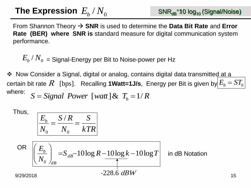
The Expression 0/ NEb
From Shannon Theory SNR is used to determine the Data Bit Rate and Error
Rate (BER) where SNR is standard measure for digital communication system
performance.
0/ NEb = Signal-Energy per Bit to Noise-power per Hz
bb STE Now Consider a Signal, digital or analog, contains digital data transmitted at a
certain bit rate R [bps]. Recalling 1Watt=1J/s, Energy per Bit is given by
where: RTwattPowerSignalS b /1&][
kTR
S
N
RS
N
Eb 00
/Thus,
TkRSN
EdB
dB
b log10log10log100
in dB Notation
OR
-228.6 dBW
SNRdB=10 log10 (Signal/Noise)
9/29/2018 16
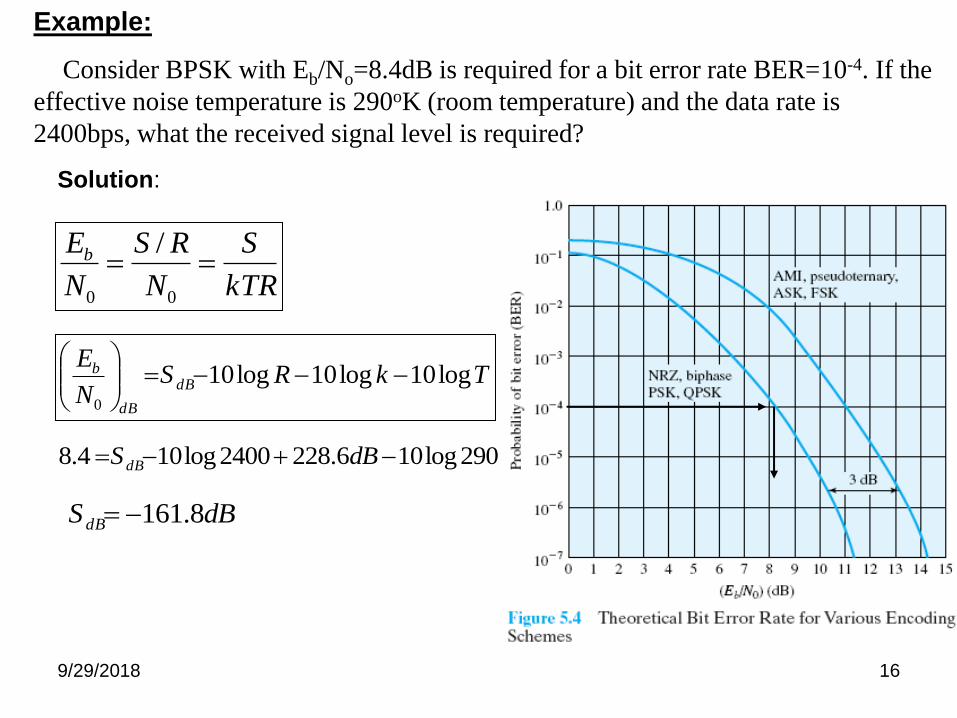
Example:
Consider BPSK with Eb/No=8.4dB is required for a bit error rate BER=10-4. If the
effective noise temperature is 290oK (room temperature) and the data rate is
2400bps, what the received signal level is required?
Solution:
TkRSN
EdB
dB
b log10log10log100
290log106.2282400log104.8 dBS dB
dBS dB 8.161
kTR
S
N
RS
N
Eb 00
/
9/29/2018 17
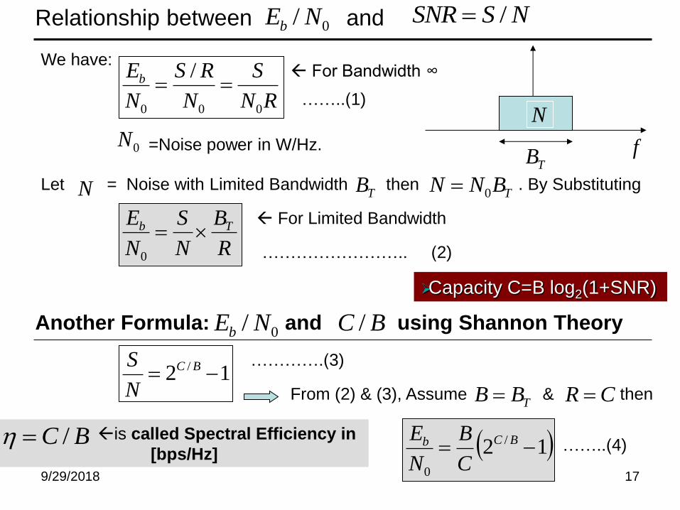
is called Spectral Efficiency in
[bps/Hz]
Relationship between and 0/ NEbNSSNR /
RN
S
N
RS
N
Eb
000
/
0N =Noise power in W/Hz.
N TB TBNN 0TB
R
B
N
S
N
E Tb 0
We have:
Let = Noise with Limited Bandwidth then . By Substituting
N
f
For Limited Bandwidth
For Bandwidth ∞
Another Formula: and using Shannon Theory 0/ NEb
12 / BC
N
S
12 /
0
BCb
C
B
N
E
From (2) & (3), Assume & then TBB
……..(1)
…………………….. (2)
………….(3)
CR
Capacity C=B log2(1+SNR)
……..(4)
BC /
BC /
9/29/2018 18
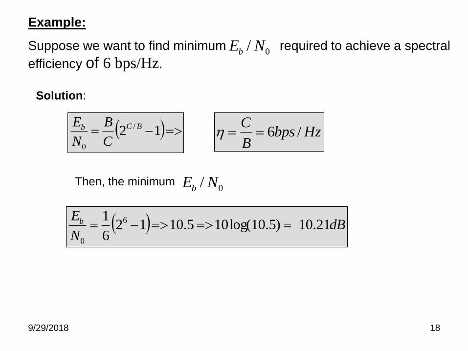
Example:
Suppose we want to find minimum required to achieve a spectral
efficiency of 6 bps/Hz. 0/ NEb
Solution:
12 /
0
BCb
C
B
N
E
dBN
Eb 21.10)5.10log(105.10126
1 6
0
HzbpsB
C/6
Then, the minimum 0/ NEb
9/29/2018 19
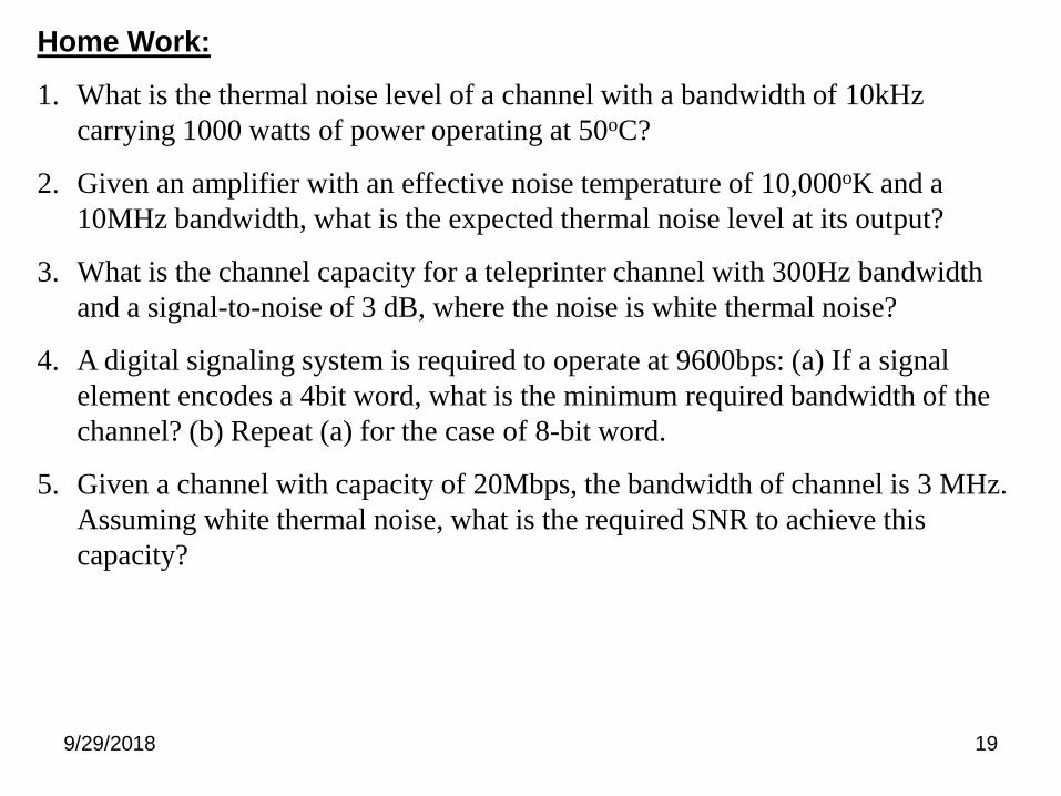
Home Work:
1. What is the thermal noise level of a channel with a bandwidth of 10kHz
carrying 1000 watts of power operating at 50oC?
2. Given an amplifier with an effective noise temperature of 10,000oK and a
10MHz bandwidth, what is the expected thermal noise level at its output?
3. What is the channel capacity for a teleprinter channel with 300Hz bandwidth
and a signal-to-noise of 3 dB, where the noise is white thermal noise?
4. A digital signaling system is required to operate at 9600bps: (a) If a signal
element encodes a 4bit word, what is the minimum required bandwidth of the
channel? (b) Repeat (a) for the case of 8-bit word.
5. Given a channel with capacity of 20Mbps, the bandwidth of channel is 3 MHz.
Assuming white thermal noise, what is the required SNR to achieve this
capacity?
9/29/2018 20
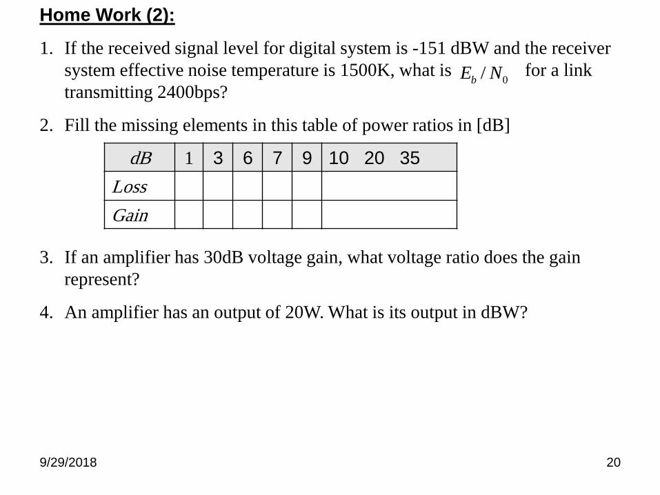
Home Work (2):
1. If the received signal level for digital system is -151 dBW and the receiver
system effective noise temperature is 1500K, what is for a link
transmitting 2400bps?
2. Fill the missing elements in this table of power ratios in [dB]
3. If an amplifier has 30dB voltage gain, what voltage ratio does the gain
represent?
4. An amplifier has an output of 20W. What is its output in dBW?
0/ NEb
dB 1 3 6 7 9 10 20 35
Loss
Gain
9/29/2018 21
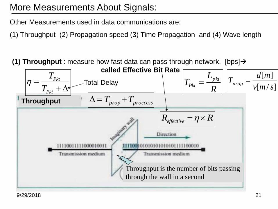
More Measurements About Signals:
Other Measurements used in data communications are:
(1) Throughput (2) Propagation speed (3) Time Propagation and (4) Wave length
(1) Throughput : measure how fast data can pass through network. [bps]
called Effective Bit Rate
Throughput
Throughput is the number of bits passing
through the wall in a second
Pkt
Pkt
T
T
proccessprop TT
Total Delay R
LT
pkt
Pkt ]/[
][.
smv
mdTprop
RReffective
9/29/2018 22
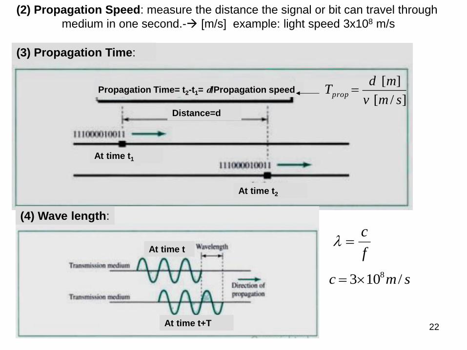
(2) Propagation Speed: measure the distance the signal or bit can travel through
medium in one second.- [m/s] example: light speed 3x10⁸ m/s
]/[
][
smv
mdTprop
f
c
smc /103 8
(3) Propagation Time:
Distance=d
At time t1
At time t2
Propagation Time= t2-t1= d/Propagation speed
(4) Wave length:
At time t+T
At time t
9/29/2018 23
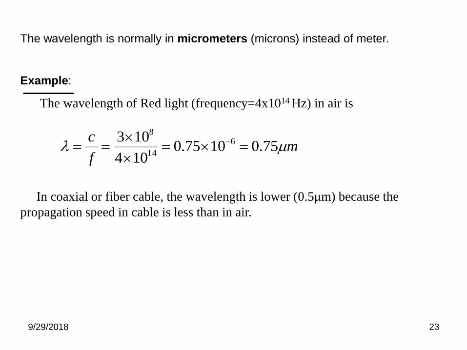
The wavelength is normally in micrometers (microns) instead of meter.
Example:
The wavelength of Red light (frequency=4x10¹⁴ Hz) in air is
In coaxial or fiber cable, the wavelength is lower (0.5μm) because the
propagation speed in cable is less than in air.
mf
c 75.01075.0
104
103 6
14
8
9/29/2018 24
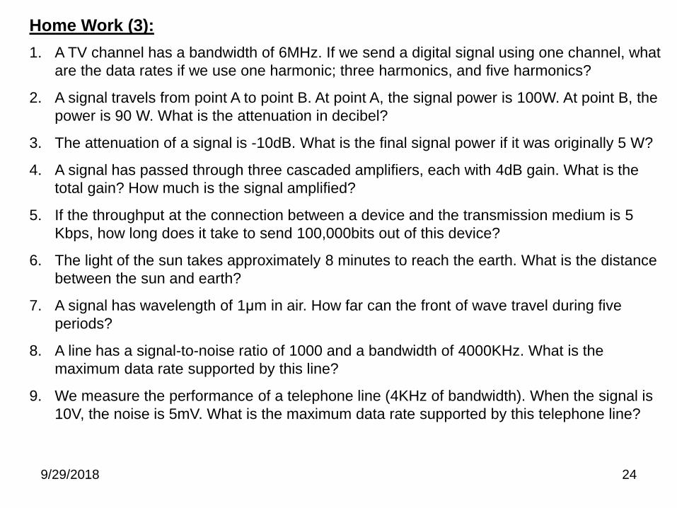
Home Work (3):
1. A TV channel has a bandwidth of 6MHz. If we send a digital signal using one channel, what
are the data rates if we use one harmonic; three harmonics, and five harmonics?
2. A signal travels from point A to point B. At point A, the signal power is 100W. At point B, the
power is 90 W. What is the attenuation in decibel?
3. The attenuation of a signal is -10dB. What is the final signal power if it was originally 5 W?
4. A signal has passed through three cascaded amplifiers, each with 4dB gain. What is the
total gain? How much is the signal amplified?
5. If the throughput at the connection between a device and the transmission medium is 5
Kbps, how long does it take to send 100,000bits out of this device?
6. The light of the sun takes approximately 8 minutes to reach the earth. What is the distance
between the sun and earth?
7. A signal has wavelength of 1μm in air. How far can the front of wave travel during five
periods?
8. A line has a signal-to-noise ratio of 1000 and a bandwidth of 4000KHz. What is the
maximum data rate supported by this line?
9. We measure the performance of a telephone line (4KHz of bandwidth). When the signal is
10V, the noise is 5mV. What is the maximum data rate supported by this telephone line?
9/29/2018 25
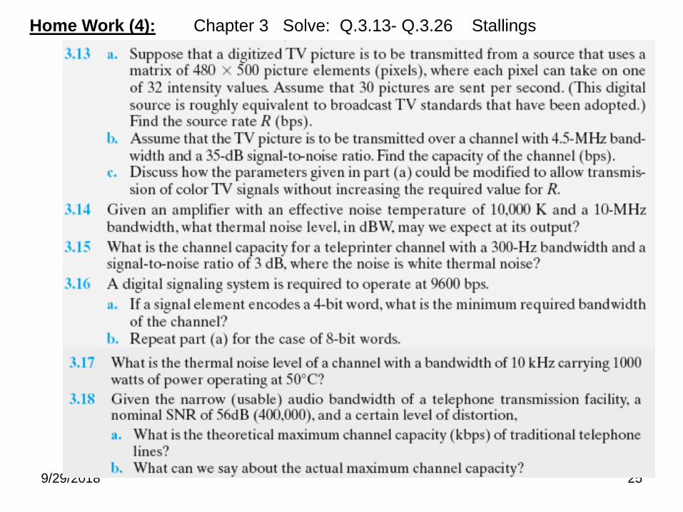
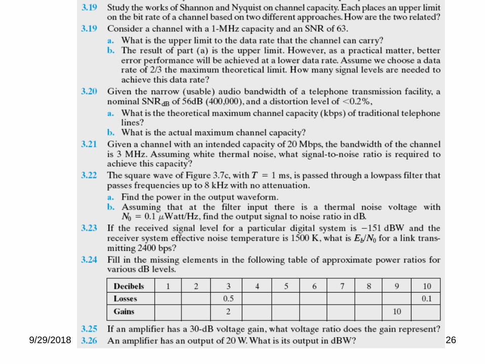
Home Work (4): Chapter 3 Solve: Q.3.13- Q.3.26 Stallings
9/29/2018 26
9/29/2018 27
9/29/2018 28
9/29/2018 29

9/29/2018 30
9/29/2018 31
9/29/2018 32
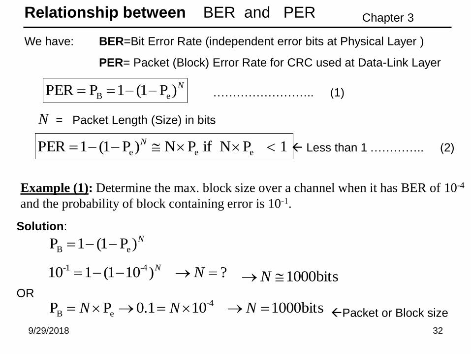
Relationship between BER and PER
N)P1(1PPER eB
N
We have:
= Packet Length (Size) in bits
Less than 1
BER=Bit Error Rate (independent error bits at Physical Layer )
PER= Packet (Block) Error Rate for CRC used at Data-Link Layer
Example (1): Determine the max. block size over a channel when it has BER of 10-4
and the probability of block containing error is 10-1.
………….. (2)
…………………….. (1)
1PNifPN)P1(1PER eee N
N)P1(1P eB
Solution:
?)101(110 -4-1 NN
bits1000N
bits1000101.0PP -4
eB NNNOR
Packet or Block size
Chapter 3
9/29/2018 33
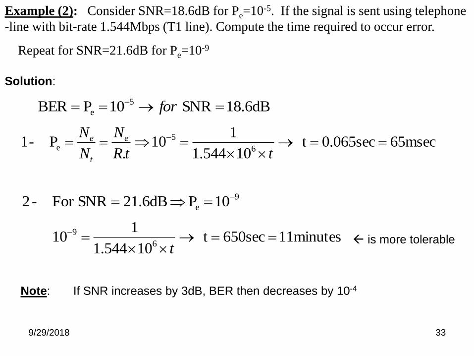
Example (2): Consider SNR=18.6dB for Pe=10-5. If the signal is sent using telephone
-line with bit-rate 1.544Mbps (T1 line). Compute the time required to occur error.
Repeat for SNR=21.6dB for Pe=10-9
Solution:
18.6dBSNR10PBER 5
e for
65msec0.065sect10544.1
110
.P -1
6
5
e
ttR
N
N
N e
t
e
9
e 10P21.6dBSNRFor -2
11minutes650sect10544.1
110
6
9
t is more tolerable
Note: If SNR increases by 3dB, BER then decreases by 10-4
9/29/2018 34
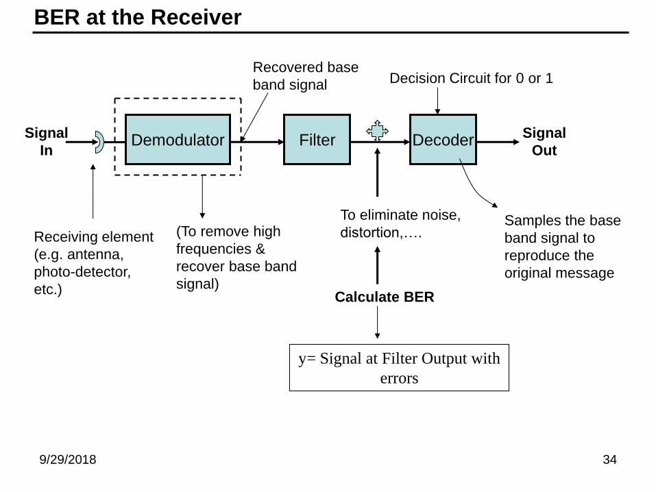
BER at the Receiver
Demodulator Filter Decoder Signal
In
Signal
Out
Receiving element
(e.g. antenna,
photo-detector,
etc.)
(To remove high
frequencies &
recover base band
signal)
Recovered base
band signal
To eliminate noise,
distortion,….
Calculate BER
Decision Circuit for 0 or 1
Samples the base
band signal to
reproduce the
original message
y= Signal at Filter Output with
errors
9/29/2018 35
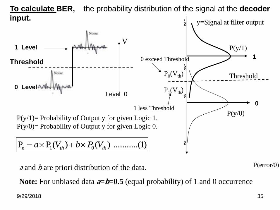
To calculate BER, the probability distribution of the signal at the decoder
input.
P(y/1)
y=Signal at filter output
P(y/0)
-∞
-∞
∞
∞
Threshold P0(Vth)
P1(Vth)
0 exceed Threshold
1 less Threshold
0 Level
Threshold
1 Level
Level 0
V
1
0
P(y/1)= Probability of Output y for given Logic 1.
P(y/0)= Probability of Output y for given Logic 0.
P(error/0)a and b are priori distribution of the data.
Note: For unbiased data a=b=0.5 (equal probability) of 1 and 0 occurrence
)1.(..........)()(PP 01e thth VPbVa

9/29/2018 36
We have Two steps:
1. The Noise Statistics: Assume n be a noise amplitude defined by Gaussian
Probability Density Function (PDF) distribution with zero-mean value (dc=0).
)2/( 22
2
1)(
nenf
n
Logic 0 0
Logic 1 V
2/VVth
Unbiased signal
PowerNoiseTotal2
2. To compute Pe: Assume Unbiased signal (data), assume all pulses has V amplitude
dvedyyfdyyPVP v
VV V
th
)2/(
2/2/ 2/
00
22
2
1)()0/()(
dvedyyfdyyPVP Vv
VV V
th
)2/)((
2/2/ 2/
11
22
2
1)()1/()(
Logic 0 0
Logic 1 V
)2.......(P(error/0)P(error/1)2
1)(P)(P
2
1P 01e thth VV )
2(Pe
VQ