Chapter 18 SUBSTRUCTURES - dot.nv.gov
24
NDOT STRUCTURES MANUAL September 2008 Chapter 18 SUBSTRUCTURES
Transcript of Chapter 18 SUBSTRUCTURES - dot.nv.gov
NDOT STRUCTURES MANUAL
September 2008
Chapter 18
SUBSTRUCTURES

SUBSTRUCTURES September 2008
18-i
Table of Contents
Section Page 18.1 ABUTMENTS/WINGWALLS ................................................................................... 18-1
18.1.1 General..................................................................................................... 18-1 18.1.2 Static and Quasi-Static Loads .................................................................. 18-1 18.1.3 Seismic Analysis and Design ................................................................... 18-1
18.1.3.1 General ................................................................................... 18-1 18.1.3.2 Integral and Dozer Abutments ................................................ 18-2 18.1.3.3 Seat Abutments ...................................................................... 18-3
18.1.4 General Abutment/Wingwall Design and Detailing Criteria ...................... 18-3 18.1.5 Integral Abutments ................................................................................... 18-4
18.1.5.1 Usage ..................................................................................... 18-4 18.1.5.2 Diaphragm-With-Footing......................................................... 18-4 18.1.5.3 Diaphragm-With-Driven-Pile ................................................... 18-6
18.1.6 Seat Abutments ........................................................................................ 18-6 18.1.7 Dozer Abutments...................................................................................... 18-6 18.1.8 Piles.......................................................................................................... 18-11
18.1.8.1 General ................................................................................... 18-11 18.1.8.2 Piles for Diaphragm-With-Driven-Pile Abutments ................... 18-11 18.1.8.3 Piles for Seat Abutments ........................................................ 18-11
18.1.9 Wingwalls ................................................................................................. 18-11 18.1.10 Abutment Construction Joints................................................................... 18-12 18.1.11 Drainage................................................................................................... 18-12
18.2 PIERS ..................................................................................................................... 18-13
18.2.1 Design Preferences.................................................................................. 18-13 18.2.2 Pier Caps.................................................................................................. 18-13
18.2.2.1 Usage ..................................................................................... 18-13 18.2.2.2 Cap Width ............................................................................... 18-13 18.2.2.3 Drop Caps............................................................................... 18-13 18.2.2.4 Integral Pier Cap..................................................................... 18-14
18.2.3 Column Cross Sections ............................................................................ 18-14 18.2.4 Column Reinforcement............................................................................. 18-16
18.2.4.1 General ................................................................................... 18-16 18.2.4.2 Transverse Reinforcement...................................................... 18-16 18.2.4.3 Longitudinal Reinforcement .................................................... 18-18 18.2.4.4 Compression Member Connection to Caps............................ 18-18
18.2.5 Column Construction Joints...................................................................... 18-18 18.2.6 Multi-Column Piers ................................................................................... 18-18

SUBSTRUCTURES September 2008
18-ii
Table of Contents (Continued)
Section Page
18.2.7 Single-Column Piers................................................................................. 18-19 18.2.8 Pier Walls ................................................................................................. 18-19 18.2.9 Dynamic Load Allowance (IM).................................................................. 18-19 18.2.10 Moment-Magnification .............................................................................. 18-19
SUBSTRUCTURES September 2008
18-1
Chapter 18 SUBSTRUCTURES
Section 11 of the LRFD Bridge Design Specifications discusses design and detailing requirements for abutments, piers and walls. This Chapter presents NDOT supplementary information on the design of these structural elements. Section 11.6 of the NDOT Structures Manual presents NDOT criteria for the selection of substructure components within the context of structure-type selection.
18.1 ABUTMENTS/WINGWALLS
18.1.1 General
See Section 11.6.2 for NDOT practices on the selection of an abutment type.
An abutment includes an end diaphragm, a stem wall and wingwalls. A stem wall or diaphragm functions as a wall providing lateral support for fill material on which the roadway rests immediately adjacent to the bridge. Abutments shall generally be of the cast-in-place, reinforced concrete type and shall be founded on spread footings, drilled shafts or driven pile footings.
Do not use MSE wall abutments except when approved by the Chief Structures Engineer. When an MSE wall abutment is allowed, the abutment shall be founded on piles and not on a spread footing. The piles should be isolated from the MSE backfill to eliminate downdrag and should be founded in the soils below the MSE wall. Section 23.2 discusses the use and design of MSE walls in more detail.
18.1.2 Static and Quasi-Static Loads
Reference: LRFD Articles 3.11, 11.6.1.1 and 11.6.1.3
The static earth pressure shall be determined in accordance with LRFD Article 3.11.
18.1.3 Seismic Analysis and Design
Reference: LRFD Article 11.6.5
18.1.3.1 General
NDOT uses a dynamic analysis for multi-span structures. A dynamic analysis is not required for single-span bridges.
For single-span structures, the longitudinal seismic design force at the abutments is the structure weight multiplied by the acceleration coefficient. Because only one abutment resists this force at any time, each abutment is designed to resist the entire seismic force.
For single-span structures, the transverse seismic design force at the abutment is one-half the structure weight multiplied by the acceleration coefficient. Concrete shear keys located on the
SUBSTRUCTURES September 2008
18-2
outside edges of the bridge resist the seismic forces. When seismic forces are high or the abutment is too wide for the external keys to resist all the force, internal shear keys may be provided. Internal shear keys are undesirable because they are extremely difficult to repair after a seismic event.
Soil springs are used to model foundation stiffness. The foundation springs are included in both the longitudinal and transverse directions. Because no soil resistance is mobilized when the structure moves away from the soil, one-half of the total longitudinal stiffness is modeled at each abutment. As a result, the resulting forces at each abutment should be added together to determine the abutment design force.
An abutment must resist the seismic active soil pressure and any force-transmitted from the superstructure elastically. Longitudinal and transverse shear keys are conservatively designed to resist total seismic abutment forces. In addition, the backwalls are assumed to fail, and the columns are conservatively designed to take all of the longitudinal seismic force.
In general, typical NDOT practice in seismically active areas is to design abutments and wingwalls for reduced seismic pressures corresponding to 2.0 in to 4.0 in of displacement. However, the amount of tolerable deformation will depend on the nature of the wall, what it supports, and what is in front of the wall.
NDOT has adopted a soil stiffness of 70 ksf per ft of movement for dynamic modeling. This stiffness is based on test results for large movements and is applicable for displacements in the range of 1 in to 3 in. Computations of abutment stiffness with soil pressures can be found in the FHWA Seismic Design of Highway Bridges Training Course Workbook. The procedures described therein may be used with the 70-ksf soil stiffness value.
18.1.3.2 Integral and Dozer Abutments
Typical NDOT diaphragm-with-footing abutments are constructed with a free-sliding diaphragm on a spread footing or pile cap. The abutment is constructed with a constant width gap (normally 1 in), filled with expansion material, between the abutment diaphragm and footing shear keys. The frictional force between the diaphragm-footing interface at the opposite abutment is conservatively neglected. An analysis is performed using an initial estimate of foundation stiffness equal to the stiffness of the backfill soil. The resulting abutment displacements are checked and compared to the width of the gap. If the predicted displacements are equal to or less than the gap width, the model is deemed satisfactory and the overall design proceeds. If the predicted displacements exceed the gap width, the shear keys are engaged and the structure is reanalyzed with increased foundation stiffness. This process is repeated until the displacements are close to the gap width. Resulting soil pressures behind the abutment wall are checked against the recommended ultimate soil capacity of 5 ksf for granular backfill material. If the calculated soil pressure exceeds the ultimate capacity and the shear keys have not been engaged, a reduced effective stiffness equal to the ultimate capacity divided by the displacement is used.
Diaphragm-with-pile and dozer abutments are modeled in a similar manner with the exception that multiple iterations are not necessary, provided that the maximum values of abutment displacement and backfill soil pressure are not exceeded. Pile stiffness is added to the soil stiffness to compute the foundation stiffness of diaphragm-with-pile abutments.
The assumption is made that, for diaphragm-with-footing abutments, the expansion joint material used to fill the gap between the abutment diaphragm and footing shear keys crushes under load to one quarter of its original thickness. The gap width between the shear keys and
SUBSTRUCTURES September 2008
18-3
abutment diaphragm should be set at twice the expected thermal displacement with a 1-in minimum width at the back face of the diaphragm and ½-in minimum at the sides. The effects of long-term elastic shortening must be considered for setting the gap width on prestressed concrete structures.
Reinforcing steel in the front face of diaphragm-with-footing stem wall is designed to resist a minimum frictional force at the diaphragm-footing interface where the diaphragm slides away from the abutment fill. A minimum force equivalent to 15% of the dead-load reaction at the top of footing is assumed. This represents the force needed to overcome the friction between the stem wall and footing caused by temperature or seismic movements. Serviceability requirements are also checked for this loading.
Reinforcing is provided in the back face of the integral abutment stem walls and dozer abutment extensions to resist static and dynamic forces from the abutment backfill. For the static load combinations, the diaphragm is designed for the passive soil pressure behind the abutment. The minimum frictional force described above must also be included for diaphragm-with-footing abutments. Design loading for the dynamic load combination consists of the resulting soil pressure due to the seismic abutment shear force. The design force may be conservatively applied at the bottom of the stem wall. Although integral abutments are designed using elastic methods, stirrups are provided in the upper half of the stem walls below the superstructure to resist potential plastic hinging forces. Longitudinal and transverse shear keys are conservatively designed to resist total seismic abutment forces. For footings supported on piles, shear keys should have a resistance that is less that 75% of the pile resistance.
18.1.3.3 Seat Abutments
For the dynamic analysis of continuous structures, abutment spring constants are used to model the movement needed to engage shear keys and restrainers only; otherwise, the abutment is considered a fixed, pinned or free-support, depending on the degree of freedom being considered.
The stem wall and back wall of a seat abutment are designed for a minimum equivalent fluid pressure of 36 pcf and for lateral seismic pressures.
18.1.4 General Abutment/Wingwall Design and Detailing Criteria
The following applies to the design and detailing of abutments and wingwalls:
1. Granular Backfill. See the NDOT Standard Specifications for Road and Bridge Construction.
2. Expansion Joints. Vertical expansion joints should be considered for wall lengths exceeding 125 ft in length. In this case, a water stop or other means of control shall be used to prevent leakage.
3. Abutment Top Surfaces. Abutment seats at bearing locations shall be level. For seat abutments, the remaining exposed top surfaces shall be transversely sloped to provide adequate drainage.
4. Approach Slab Seat. Provide a minimum 12-in approach-slab seat. Use restrainer units for all approach slabs that are not otherwise connected to the abutment or superstructure.
SUBSTRUCTURES September 2008
18-4
5. Dead Load. NDOT policy is to include one-half of the dead load of the approach slab as an abutment dead load.
6. Skewed Bridges. For skew angles greater than 30°, detail a 3-in minimum chamfer at acute corners.
7. Soil Reinforcements. Soil reinforcements (such as steel strips and bar mats commonly used in mechanically stabilized earth (MSE) wall construction) shall not be used as attachments to abutment diaphragms or stem walls in an attempt to resist lateral loads applied to these components.
8. Reinforcement. Section 14.3 discusses NDOT practices for the reinforcement of structural concrete (e.g., concrete cover, bar spacing, corrosion protection). The design of abutments and wingwalls shall meet all applicable requirements in Section 14.3.
18.1.5 Integral Abutments
Reference: LRFD Article 11.6.2.1
18.1.5.1 Usage
Section 11.6.2 discusses NDOT practices for the use of integral abutments. In addition, their use should be limited to a maximum height of 9 ft as measured from the bottom of the soffit to the bottom of the wall, or twice the depth of the superstructure, whichever is less.
18.1.5.2 Diaphragm-With-Footing
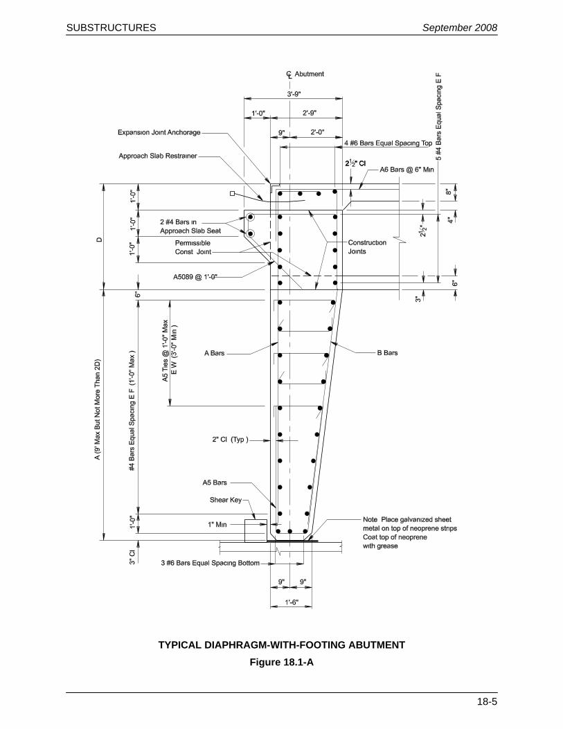
Figure 18.1-A shows a typical diaphragm-with-footing abutment. Diaphragm-with-footing abutment details shall meet the following requirements:
1. Abutment Height. If the extension of the end diaphragm down to the footing (shown as “A” in Figure 18.1-A) exceeds two times the superstructure depth (shown as “D” in the Figure), the bridge should be modeled as a rigid frame.
2. Superstructure Flexural Resistance. Provide flexural resistance at the end of the superstructure equal to 130% of the diaphragm flexural resistance (#6 bars @ 6 in as a minimum).
3. Size and Spacing of A and B Bars. The size and spacing of the A and B bars shown in Figure 18.1-A shall be determined by design.
4. Top and Bottom Slab Reinforcing. Extend the top and bottom slab reinforcing through the abutment diaphragm.
SUBSTRUCTURES September 2008
18-5
TYPICAL DIAPHRAGM-WITH-FOOTING ABUTMENT Figure 18.1-A
SUBSTRUCTURES September 2008
18-6
18.1.5.3 Diaphragm-With-Driven-Pile
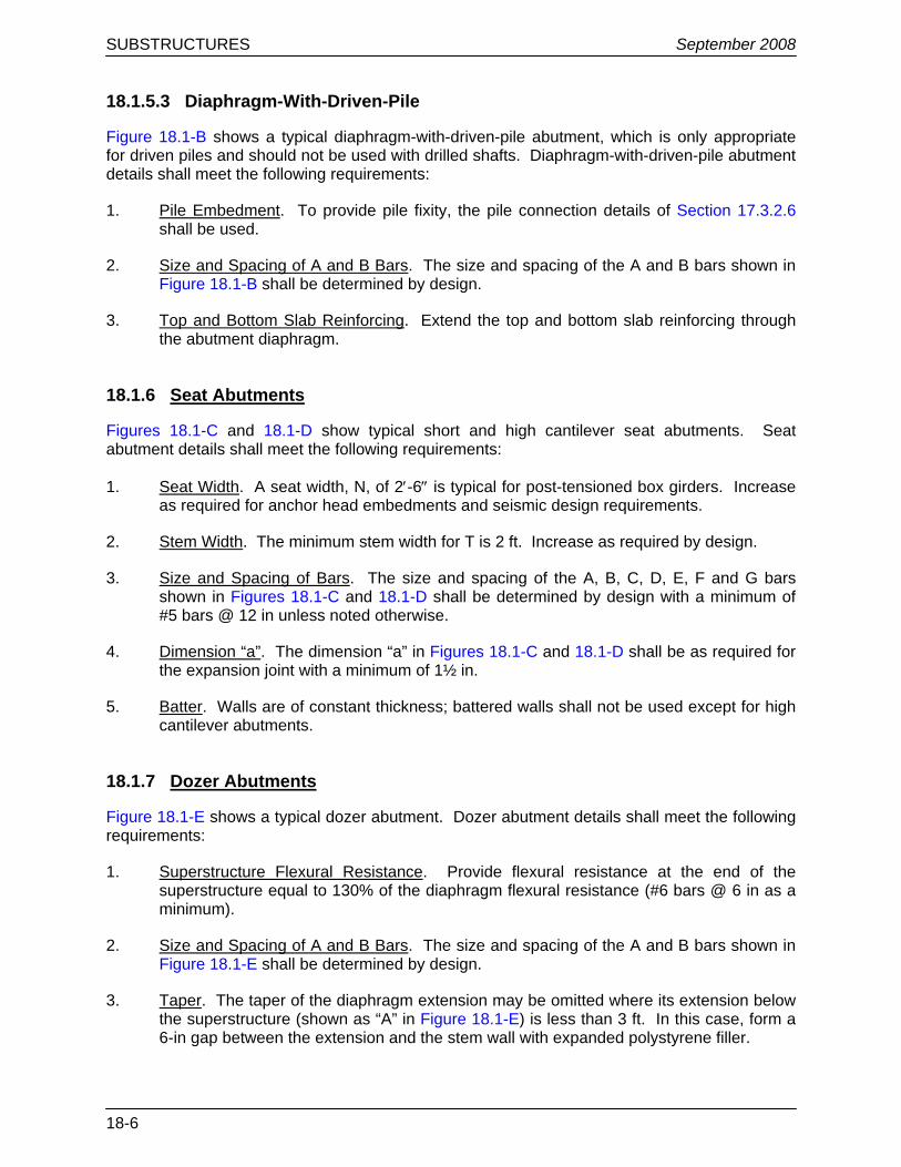
Figure 18.1-B shows a typical diaphragm-with-driven-pile abutment, which is only appropriate for driven piles and should not be used with drilled shafts. Diaphragm-with-driven-pile abutment details shall meet the following requirements:
1. Pile Embedment. To provide pile fixity, the pile connection details of Section 17.3.2.6 shall be used.
2. Size and Spacing of A and B Bars. The size and spacing of the A and B bars shown in Figure 18.1-B shall be determined by design.
3. Top and Bottom Slab Reinforcing. Extend the top and bottom slab reinforcing through the abutment diaphragm.
18.1.6 Seat Abutments
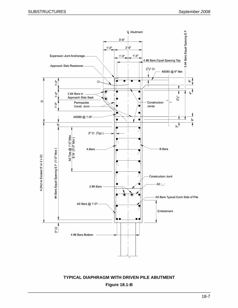
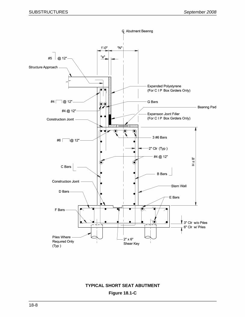
Figures 18.1-C and 18.1-D show typical short and high cantilever seat abutments. Seat abutment details shall meet the following requirements:
1. Seat Width. A seat width, N, of 2′-6″ is typical for post-tensioned box girders. Increase as required for anchor head embedments and seismic design requirements.
2. Stem Width. The minimum stem width for T is 2 ft. Increase as required by design.
3. Size and Spacing of Bars. The size and spacing of the A, B, C, D, E, F and G bars shown in Figures 18.1-C and 18.1-D shall be determined by design with a minimum of #5 bars @ 12 in unless noted otherwise.
4. Dimension “a”. The dimension “a” in Figures 18.1-C and 18.1-D shall be as required for the expansion joint with a minimum of 1½ in.
5. Batter. Walls are of constant thickness; battered walls shall not be used except for high cantilever abutments.
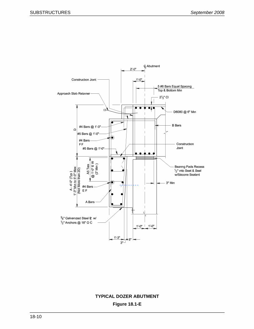
18.1.7 Dozer Abutments
Figure 18.1-E shows a typical dozer abutment. Dozer abutment details shall meet the following requirements:
1. Superstructure Flexural Resistance. Provide flexural resistance at the end of the superstructure equal to 130% of the diaphragm flexural resistance (#6 bars @ 6 in as a minimum).
2. Size and Spacing of A and B Bars. The size and spacing of the A and B bars shown in Figure 18.1-E shall be determined by design.
3. Taper. The taper of the diaphragm extension may be omitted where its extension below the superstructure (shown as “A” in Figure 18.1-E) is less than 3 ft. In this case, form a 6-in gap between the extension and the stem wall with expanded polystyrene filler.
SUBSTRUCTURES September 2008
18-7
TYPICAL DIAPHRAGM WITH DRIVEN PILE ABUTMENT Figure 18.1-B
SUBSTRUCTURES September 2008
18-8
TYPICAL SHORT SEAT ABUTMENT Figure 18.1-C
SUBSTRUCTURES September 2008
18-9
TYPICAL HIGH CANTILEVER ABUTMENT Figure 18.1-D
SUBSTRUCTURES September 2008
18-10
TYPICAL DOZER ABUTMENT Figure 18.1-E
SUBSTRUCTURES September 2008
18-11
18.1.8 Piles
Reference: LRFD Article 10.7
This discussion specifically addresses the use of driven piles with abutments. See Section 17.3 for additional information on piles.
18.1.8.1 General
The following criteria apply to piles for all abutments:
1. Number. The number of piles supporting an abutment shall not be less than three.
2. Batter. Vertical piles shall be used at integral abutments and are preferred at dozer and seat abutments. If battered piles are used, a refined analysis is required.
3. Construction. Consider the placement tolerances for all abutment types and ensure pile fit within the cap dimensions and relative to reinforcing steel.
18.1.8.2 Piles for Diaphragm-With-Driven-Pile Abutments
A single row of piles shall be used.
18.1.8.3 Piles for Seat Abutments
The following criteria apply to piles for seat abutments:
1. Pile Spacing. Consider using two rows of piles to achieve the necessary longitudinal stiffness. The minimum pile spacing is 30 in or 2½ times the pile width or as recommended by the Geotechnical Section.
2. Movement. The designer shall investigate the effects of movements due to overturning pressures or lateral pressures (e.g., ensure that the closing of joints does not occur).
18.1.9 Wingwalls
Reference: LRFD Article 11.6.1.4
Wingwalls shall be of sufficient length to retain the roadway embankment and to furnish protection against erosion. See Figure 11.6-B for the geometry of wingwalls.
With respect to abutments, the following applies to wingwalls:
1. Orientation. Typical NDOT practice is to use “parallel” wingwalls (i.e., wingwalls that are parallel to the centerline of the bridge). Occasionally, bridge or roadway geometric constraints will require the use of “perpendicular” wingwalls (i.e., wingwalls that are perpendicular to the centerline of bridge). “Flared” wingwalls are only used in combination with box culverts.
2. Thickness. The minimum thickness of any wingwall shall be 12 in.

SUBSTRUCTURES September 2008
18-12
3. Longer Parallel Wingwalls. In general, parallel wingwalls should not extend more than 20 ft behind the rear face of the abutment. If parallel wingwalls on seat abutments have a total length of more than 20 ft, investigate the use of an unattached wingwall.
4. Cantilevered Wingwalls. Use cantilevered wingwalls only on integral abutments.
5. Wingwall/Abutment Connection. The junction of the abutment and wingwall is a critical design element, requiring special considerations. Typical NDOT practice is to use a 2-ft triangular fillet at the junction of the back of the abutment and wingwall. Use fillet reinforcement with a minimum of #6 reinforcing bars at 12-in spacings properly anchored into the wingwall and abutment (see the NDOT Bridge Drafting Guidelines).
6. Design Forces. The design forces for wingwalls are due to earth pressure only. It is NDOT practice to extend the approach slabs over the wingwall, which eliminates the live load surcharge in the design of the wingwall. Seismic forces from the soil behind the wingwall must also be considered in the design of wingwalls.
7. Unattached Wingwalls. Unattached wingwalls shall be designed as retaining walls. Unattached wingwalls are generally cast-in-place concrete retaining walls. Provide an expansion joint between the unattached wingwall and abutment. See Section 23.1 for NDOT practices on retaining walls.
18.1.10 Abutment Construction Joints
To accommodate normal construction practices, the designer should detail the following horizontal construction joints in the contract documents:
1. Integral Abutments. A horizontal construction joint shall be detailed at the top of the end diaphragm at the joint with the soffit. See Figures 18.1-A and 18.1-B for this mandatory and other optional construction joints.
2. Seat Abutments. A horizontal construction joint shall be detailed between the top of the abutment seat and the bottom of the backwall. Some expansion joint types may require another construction joint at the approach slab seat.
3. Wingwalls. A permissible horizontal construction joint shall be detailed at an elevation that is the same as the top of the abutment seat.
Planned vertical construction joints are normally associated with staged construction issues. Make provisions for splicing or mechanical reinforcing couplers on horizontal reinforcing steel. Vertical reinforcing steel should be at least 3 in from the construction joint.
18.1.11 Drainage
The NDOT Bridge Drafting Guidelines provides a detail for the design of weepholes, which are intended to provide positive drainage as needed in the embankment behind the abutment and wingwalls. Provide weepholes spaced every 15 ft horizontally and located 3 in to 6 in above finished grade.
SUBSTRUCTURES September 2008
18-13
18.2 PIERS
Reference: LRFD Article 11.7
18.2.1 Design Preferences
Desirably, the column design will be controlled by seismic loads and not other load combinations. The columns shall be conservatively designed to take all of the longitudinal seismic force assuming that the abutment backwalls fail. A longitudinal open joint should be used where transverse temperature controls the column design.
18.2.2 Pier Caps
18.2.2.1 Usage
In general, NDOT uses integral caps and drop pier caps supported by a single column, multiple columns or a solid pier wall. See Section 11.6.3 for more information.
Use an integral pier cap for cast-in-place concrete bridges and drop caps for steel and precast concrete girder bridges. An integral pier cap may be used for steel and precast concrete girder bridges where vertical clearance restrictions exist under the cap.
An outrigger cap is an integral cap that extends beyond the edge of the bridge superstructure. They are used where columns cannot be placed within the width of the bridge superstructure. The design shall consider the torsional effects resulting from longitudinal seismic displacements. A pin connection is preferred at the interface between the column top and bottom of the outrigger cap to minimize torsion in the cap.
18.2.2.2 Cap Width
The width of pier caps shall project beyond the sides of columns. The added width of the cap shall be a minimum of 3 in on each side of the column for a total of 6 in by which the cap is larger than the column. This width will reduce the reinforcement interference between the column and cap. The cap will also have short cantilevered ends, when practical, to balance positive and negative moments in the cap. These caps shall be designed to meet the deflection requirements of LRFD Article 2.5.2.6.2.
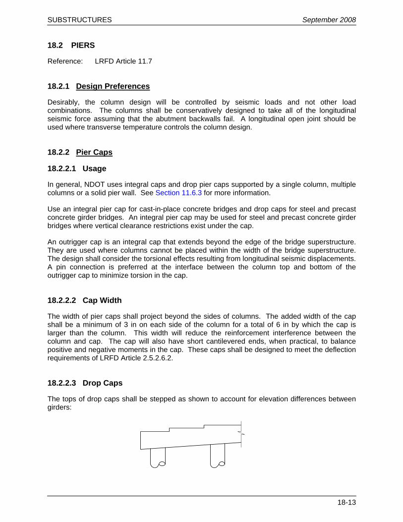
18.2.2.3 Drop Caps
The tops of drop caps shall be stepped as shown to account for elevation differences between girders:
SUBSTRUCTURES September 2008
18-14
The drop cap steps should be vertical, and the bearing surfaces should be level. For planar (superelevated) cross sections, the bottom of the cap shall be sloped at the same rate as the cross slope of the top of the bridge deck. For crowned sections, the bottom of the cap shall be level.
18.2.2.4 Integral Pier Cap
For integral pier caps, an additional layer of longitudinal reinforcement shall be placed approximately 3 in below the construction joint between the deck and cap, or lower if necessary to clear prestressing ducts. This reinforcement shall be designed for flexure using the Strength I load combination of LRFD Table 3.4.1-1, considering the dead load negative moment of that portion of the cap and superstructure located beneath the construction joint and within 10 ft of each side face of the cap. The Service limit states and shear design are not required for this condition. This reinforcement may be included in computing the flexural capacity of the cap only if a stress and strain compatibility analysis is made to determine the stress in the bars.
18.2.3 Column Cross Sections
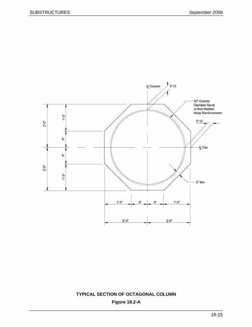
Reinforced concrete columns have traditionally been constructed with the octagonal shape shown in Figure 18.2-A. However, recently developed landscape aesthetic guidelines indicate a preference for round columns. Consult with the NDOT Landscape/Aesthetics Section for recommendations regarding column shape or other aesthetic features. Flared columns should not be used for new or replacement bridges. Flared columns may be considered for use on bridge widenings with the written approval of the Chief Structures Engineer.
For single-columns, the cross section is 4-ft thick with a variable width.
Where a pier wall is used, the wall shall be solid for its entire height. The minimum thickness is 2 ft (2′-6″ for railroad crash walls) and may be widened at the top to accommodate the bridge seat where required.
Caps shall be at least 6 in wider than the column’s greatest dimension. Seismic requirements for girder-seat widths may control cap width.
Where columns are supported on isolated drilled shafts, the shaft diameter is typically enlarged relative to the column to force plastic hinging in the column and protect the drilled shaft from inelastic action. The drilled shaft diameter is typically 18 in larger than the column diameter. The bridge designer must confirm that the diameters selected for the column and shaft will accommodate the overlapping reinforcing steel cages and clear cover requirements in both the column and drilled shaft. Refer to Figure 17.4-A in Chapter 17.
SUBSTRUCTURES September 2008
18-15
TYPICAL SECTION OF OCTAGONAL COLUMN Figure 18.2-A
SUBSTRUCTURES September 2008
18-16
18.2.4 Column Reinforcement
18.2.4.1 General
Section 14.3 discusses NDOT practices for the reinforcement of structural concrete. This includes:
• concrete cover, • bar spacing, • lateral confinement reinforcement, • corrosion protection, • development of reinforcement, and • splices. The design of concrete pier columns shall meet all applicable requirements in Section 14.3.
18.2.4.2 Transverse Reinforcement
Reference: LRFD Article 5.10.11
18.2.4.2.1 General
Spirals or butt-welded spliced hoops shall be used as transverse reinforcing steel in octagonal or round columns. Ties are used in rectangular columns or shapes where spirals or hoops cannot be used. Reinforce columns with oblong cross sections and interlocking hoops with a center-to-center spacing not to exceed ¾ times the diameter of the cage. The overlaps shall be interlocked by a minimum of four bars. Figure 18.2-B illustrates the detailing of an oblong column.
18.2.4.2.2 Spiral Splices
Almost all spiral reinforcement will require a splice. LRFD Article 5.10.11 provides requirements for splices in spiral reinforcement. The contract documents shall indicate plastic hinge regions where a spiral splice is not allowed. Refer to Section 14.3.1.8.2.
A lapped splice, where permitted, shall consist of an overlap distance of 60 bar diameters or 1½ column diameters whichever is more. The ends of both spirals shall terminate in a 135° hook, wrapped around a longitudinal bar, and having a tail length of at least 6 in. A detail or description of the lapped splice should be provided in the contract documents.
See Section 14.3.1.8 for a discussion on NDOT practices for welded and mechanical splices.
At locations where the spiral reinforcement extends into a footing or cap, the spiral reinforcement can be discontinuous. This allows easier placement of the top mat of footing or bottom mat of cap reinforcement. A detail or note shall be provided in the plans that shows an allowed discontinuity in the spiral with a splice.

SUBSTRUCTURES September 2008
18-17
TYPICAL SECTION OF MULTI-SPIRAL COLUMN Figure 18.2-B
SUBSTRUCTURES September 2008
18-18
18.2.4.3 Longitudinal Reinforcement
Reference: LRFD Article 5.10.11
Longitudinal column reinforcing bars shall be #8 or larger, with #10 bars being the preferred minimum. Detail the longitudinal reinforcing steel continuous with a maximum spacing of 8 in center-to-center. The longitudinal column reinforcing bars must be fully developed where these bars enter into the pier cap and the spread footing, pile cap or drilled shaft.
The preferred detail for longitudinal reinforcement is continuous, unspliced reinforcement. A note on the plans should state that splices will not be allowed in the longitudinal reinforcement.
If column heights require splices, the provisions in LRFD Article 5.10.11 shall be used. Mechanical couplers or lap splices shall be used for splicing the longitudinal reinforcing steel. Do not locate splices within the plastic-hinge regions of the column. Refer to Section 14.3.1.8.2. A minimum stagger of 2′-0″ between adjacent splices shall be required and the locations shown in the plans. Splices in bundled bars shall also be staggered at a minimum of 2′-0″. If epoxy-coated bars are used, mechanical couplers shall be tested with reinforcing bars coated as required for the bridge, and the couplers shall be coated with a compatible coating.
Proposals by contractors to change the location or type of splice from those in the contract documents should not be allowed unless approved by the bridge designer. The resolution of conflicts or errors requires special consideration.
18.2.4.4 Compression Member Connection to Caps
Longitudinal bars should terminate at a point below the top cap reinforcement or prestressing ducts. If a hook is required, it should extend toward the compression member core. Minimum clearances must be maintained for the placement of cap concrete through tremies.
18.2.5 Column Construction Joints
Construction joints shall be used at the top and bottom of the column. Where columns exceed 25 ft in height, construction joints shall be shown such that concrete pours do not exceed 25 ft in height. Where applicable, locate all construction joints at least 12 in above the water elevation expected during construction.
18.2.6 Multi-Column Piers
Concrete frame piers may be used to support a variety of superstructures. The columns may be directly supported by individual footings, a combined footing or by drilled shafts. The following applies to the design and detailing of multi-column piers:
1. Column Spacing. In general, column spacing should not exceed approximately 25 ft center to center of columns.
2. Footings. Columns founded on spread footings have typically been designed with separate footings under each column. Existing analytical techniques provide tools for the analysis of a common footing for all columns, and this configuration may result in a more economical design.
SUBSTRUCTURES September 2008
18-19
3. Compressive Reinforcing Steel in Cap or Footing. Compressive reinforcing steel tends to buckle when the cover is gone or when the concrete around the steel is weakened by compression. If the initial design indicates the need for compressive steel, the pier shall be redesigned to eliminate this need.
18.2.7 Single-Column Piers
The following applies to the design of single-column piers:
1. Cantilevers. The design of the cantilever is affected by the cantilever depth-versus-length geometry. Where the distance between the centerline of the bearing and the column is less than approximately twice the depth of the cantilever, the strut-and-tie model in LRFD Article 5.6.3 should be considered for the design of the cantilever.
2. Cantilever Reinforcement. All of the calculated cantilever reinforcement shall be extended throughout the entire length of cap. Cap stirrups shall be placed in the cap within the limits of the shaft at a minimum spacing of 12 in.
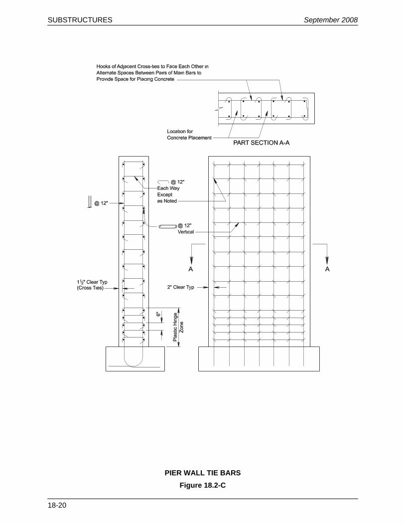
18.2.8 Pier Walls
Pier walls should be solid full height. The dimensions of the wall in the transverse direction may be reduced by providing cantilevers to form a hammerhead pier. Figure 18.2-C illustrates the typical detailing for pier wall tie bars.
18.2.9 Dynamic Load Allowance (IM)
Reference: LRFD Article 3.6.2.1
The LRFD Specifications allows the Dynamic Load Allowance (IM), traditionally called impact, to only be omitted on “foundation components that are entirely below ground level.” NDOT requires that the dynamic load allowance be considered in the structural design of pier caps, pier columns and all piles, drilled shafts and footings, only if a significant portion of these elements is above ground.
18.2.10 Moment-Magnification
Reference: LRFD Article 5.7.4
Piers, pier columns and piles are referred to as compressive members, although their design is normally controlled by flexure. In most cases, the use of the moment-magnification approach in LRFD Article 5.7.4.3 is warranted. For exceptionally tall or slender columns/shafts where the slenderness ratio (Kl/r) is greater than 100, a refined analysis, as outlined in LRFD Article 5.7.4.1, should be performed. Where P-Delta design procedures are used, consideration shall be given in the design to the initial out-of-straightness of columns and the sustained dead load.
Moment magnification is not significant in seismic design and may be ignored.
SUBSTRUCTURES September 2008
18-20
PIER WALL TIE BARS Figure 18.2-C