CFRP STRENGTHENING OF STEEL BEAMS WITH WEB … · CFRP STRENGTHENING OF STEEL BEAMS WITH WEB...
12
CFRP STRENGTHENING OF STEEL BEAMS WITH WEB OPENINGS Mohammed Altaee, Lee Cunningham, Martin Gillie 1 University of Manchester, School of Mechanical, Aerospace & Civil Engineering, Manchester, M13 9PL, UK KEYWORDS: CFRP, Finite Element Modelling, Steelwork, Strengthening, Web openings ABSTRACT Integration of services via web-openings in steel floor beams is often unavoidable in modern frame buildings. Such web-openings can significantly reduce the shear and bending strength capacity of the beams. Traditionally, the welding of additional steel plates to the opening areas is adopted as a means of strengthening and stiffening. This not only presents practical difficulties but can induce residual stresses which weaken fatigue performance of the section. This study explores the use of externally bonded carbon fibre reinforced polymer composites (CFRP) as an alternative means of strengthening. Using a non-linear finite element approach, the effect of strengthening arrangement is investigated with a view to finding the most structurally efficient layout. For the series studied significant enhancements of strength comparable to those achieved by welded plates, have been predicted. 1. INTRODUCTION Over the past two decades, carbon fibre reinforced polymer (CFRP) has been used widely among other FRP materials for strengthening of steel structures. In comparison to other commonly used FRP materials, CFRP is prevalent primarily because of its relatively high stiffness. CFRP laminates for application with steel structures are available as pultruded plates, sections and sheets. Pultruded plates are typically bonded to the steel using a two part epoxy adhesive, while the sheets can be bonded the same way or with a compatible adhesive film (Cadei et al. 2004). Many experimental, numerical and theoretical studies have been undertaken on externally bonded carbon fibre polymer (CFRP) with steel members, each study dealt with a different parameter to discover the advantages of this material. Several studies applied CFRP to the bottom flanges of steel sections as a repair or strengthening means. Deng & Lee (2007) used different lengths and thicknesses of CFRP (E = 212GPa) in strengthening of ten 127*76*13UKB steel I’sections of 1100 mm span under either three or four point static bending. It was concluded that the de-bonding mode of failure was initiated at lower load levels when the CFRP plate thickness increased and its length decreased. The maximum gain in strength (30%) was achieved in the beam with the longest bonded length (500 mm) and thinnest CFRP plate thickness (3 mm). It should be noted that for all the previous experimental investigations, the beams were laterally supported to prevent lateral torsional buckling. Colombi & Poggi (2006) tested four steel beams of 2500 mm span under static three-point bending. The beams were strengthened with two 120 mm x 1.4 mm layers of CFRP plate (E=200GPa) and the ends of the CFRP plates were wrapped with CFRP sheets which were extended up along the web to provide anchorage and prevent debonding. Although the tests were terminated before failure, after excessive deflections were observed at mid-span, the results showed that the stiffness and strength achieved an increase of 14% and 40%, respectively over the un-strengthened section.
Transcript of CFRP STRENGTHENING OF STEEL BEAMS WITH WEB … · CFRP STRENGTHENING OF STEEL BEAMS WITH WEB...
CFRP STRENGTHENING OF STEEL BEAMS
WITH WEB OPENINGS
Mohammed Altaee, Lee Cunningham, Martin Gillie
1University of Manchester,
School of Mechanical, Aerospace & Civil Engineering,
Manchester, M13 9PL, UK
KEYWORDS: CFRP, Finite Element Modelling, Steelwork, Strengthening, Web openings
ABSTRACT
Integration of services via web-openings in steel floor beams is often unavoidable in modern frame
buildings. Such web-openings can significantly reduce the shear and bending strength capacity of the
beams. Traditionally, the welding of additional steel plates to the opening areas is adopted as a means of
strengthening and stiffening. This not only presents practical difficulties but can induce residual stresses
which weaken fatigue performance of the section. This study explores the use of externally bonded
carbon fibre reinforced polymer composites (CFRP) as an alternative means of strengthening. Using a
non-linear finite element approach, the effect of strengthening arrangement is investigated with a view to
finding the most structurally efficient layout. For the series studied significant enhancements of strength
comparable to those achieved by welded plates, have been predicted.
1. INTRODUCTION
Over the past two decades, carbon fibre reinforced polymer (CFRP) has been used widely among other
FRP materials for strengthening of steel structures. In comparison to other commonly used FRP materials,
CFRP is prevalent primarily because of its relatively high stiffness. CFRP laminates for application with
steel structures are available as pultruded plates, sections and sheets. Pultruded plates are typically
bonded to the steel using a two part epoxy adhesive, while the sheets can be bonded the same way or with
a compatible adhesive film (Cadei et al. 2004).
Many experimental, numerical and theoretical studies have been undertaken on externally bonded carbon
fibre polymer (CFRP) with steel members, each study dealt with a different parameter to discover the
advantages of this material. Several studies applied CFRP to the bottom flanges of steel sections as a
repair or strengthening means. Deng & Lee (2007) used different lengths and thicknesses of CFRP (E =
212GPa) in strengthening of ten 127*76*13UKB steel I’sections of 1100 mm span under either three or
four point static bending. It was concluded that the de-bonding mode of failure was initiated at lower load
levels when the CFRP plate thickness increased and its length decreased. The maximum gain in strength
(30%) was achieved in the beam with the longest bonded length (500 mm) and thinnest CFRP plate
thickness (3 mm). It should be noted that for all the previous experimental investigations, the beams were
laterally supported to prevent lateral torsional buckling.
Colombi & Poggi (2006) tested four steel beams of 2500 mm span under static three-point bending. The
beams were strengthened with two 120 mm x 1.4 mm layers of CFRP plate (E=200GPa) and the ends of
the CFRP plates were wrapped with CFRP sheets which were extended up along the web to provide
anchorage and prevent debonding. Although the tests were terminated before failure, after excessive
deflections were observed at mid-span, the results showed that the stiffness and strength achieved an
increase of 14% and 40%, respectively over the un-strengthened section.
FRP composites have also been used to prevent web buckling in steel plate-girders by providing
additional stiffness to the webs. Okeil et al.(2009) carried out experimental and finite element (FE)
modelling on glass fibre reinforced polymer (GFRP) strengthening applied to the end web panels of plate-
girders. Test results showed that the ultimate load capacity of specimens with vertical and diagonally
placed GFRP stiffeners increased by 1.40 and 1.56 times respectively. The failure in the GFRP-
strengthened specimens was initiated by a breakdown of the steel-GFRP bond followed by immediate
out-of-plane buckling of the web.
Transferring the load between steel and CFRP composite depends mainly on the ability of the adhesive
material to maintain bond with steel, therefore some researchers focused on CFRP debonding. An
experimental study of fatigue failure showed that de-bonding of CFRP plates started in the zones of high
stress concentration at the plate ends (Bocciarelli et al. 2009). The bonding failure or delamination
between steel and CFRP composite is considered the most common failure due to the weakness of the
adhesive bond and the maximum value of the adhesive shear stress occurring at the edges of the FRP
sheet (Youssef, 2006, Zhao & Zhang, 2007).
To date, investigations of FRP strengthened steel sections have primarily focussed on un-altered, integral
sections. The introduction of openings in the web decreases the strength and stiffness of beams which
results in larger deflections. This paper presents a novel method to maintain cross-sectional capacity and
stiffness through the bonding of CFRP plates. A proposed numerical model capable of capturing key
phenomena including de-bonding, built using the finite element programme ABAQUS (2012), has been
validated using available experimental results in the literature; namely Deng and Lee (2007). Then,
simulation of CFRP-strengthened steel members is carried out using the proposed numerical model with
different web opening location and strengthening configurations.
2. FINITE ELEMENT MODEL VALIDATION:
2.1 Experimental Setup:
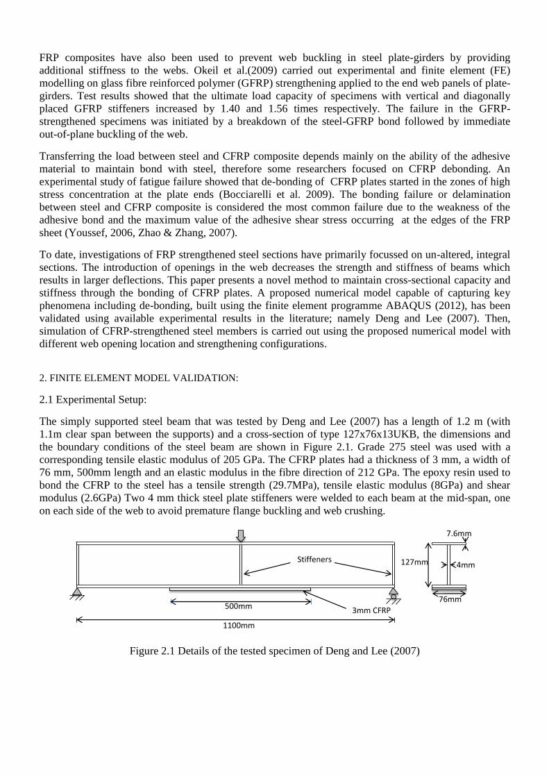
The simply supported steel beam that was tested by Deng and Lee (2007) has a length of 1.2 m (with
1.1m clear span between the supports) and a cross-section of type 127x76x13UKB, the dimensions and
the boundary conditions of the steel beam are shown in Figure 2.1. Grade 275 steel was used with a
corresponding tensile elastic modulus of 205 GPa. The CFRP plates had a thickness of 3 mm, a width of
76 mm, 500mm length and an elastic modulus in the fibre direction of 212 GPa. The epoxy resin used to
bond the CFRP to the steel has a tensile strength (29.7MPa), tensile elastic modulus (8GPa) and shear
modulus (2.6GPa) Two 4 mm thick steel plate stiffeners were welded to each beam at the mid-span, one
on each side of the web to avoid premature flange buckling and web crushing.
Figure 2.1 Details of the tested specimen of Deng and Lee (2007)
127mm
76mm
4mm
7.6mm
3mm CFRP
plate
Stiffeners
1100mm
500mm

2.2 Numerical Model:
FE models were developed for the beams, with the dimensions and support conditions as given in Figure
2.1. The general purpose shell element S4R with reduced integration was adopted for both the steel
section and the CFRP plate, while the adhesive layer was modelled using the cohesive element COHD8
provided by ABAQUS. The two full-depth stiffeners were provided on the two sides of the web in the
mid-span region, and three sides of each stiffener were tied to the top flange, the bottom flange and the
web of the cross section respectively. Similarly, the top and bottom surfaces of the adhesive layer were
tied to the bottom surface of the steel beam and the top surface of the CFRP plate respectively. The CFRP
plate was treated as an orthotropic material in the FE model (Teng et al. 2015). Following a sensitivity
study, the element mesh was based on a 15mm grid.
2.3 Damage modelling of adhesive:
The eventual failure of the bond surfaces can be modelled with ABAQUS damage models. The damage
model consists of two stages: a damage initiation and a damage evolution. The initial response of
the cohesive surfaces is linear, after a damage criterion is met, the traction-separation response can
be defined to a user-defined damage evolution law. Traction separation behaviour of cohesive
surfaces available in ABAQUS was selected to simulate the epoxy with a linear behaviour as shown in
Figure 2.2.
Figure 2.2 Traction-separation response.
2.3.1 Damage initiation
ABAQUS provides four damage initiation criteria, two of them based on the stress and the others based
on the separation, examples are the maximum nominal stress criterion, the maximum nominal strain
criterion, and the quadratic nominal stress criterion. In this study, the quadratic nominal stress criterion is
used as the damage initiation criterion, which can be represented as:
1
2
max
2
max
2
max
tsn ttt
(2-1)
Where,
tn, ts and tt : peak values of the nominal stress.
σmax is the tensile strength of the adhesive, and
τmax is the shear strength of the adhesive; the symbol < > represents the Macaulay bracket which is used
to signify that compressive stresses do not initiate damage (i.e. tn is negative and thus <tn> is equal to
zero).
2.3.2 Damage evolution
After damage initiation, a scalar damage variable D is introduced as the overall damage in the material .
The range of D is from 0 to 1, with 0 representing the undamaged case and 1, the total separation.
Subsequently, the corresponding stress components are then degraded as follows:
0,
0,1
nn
nn
n tt
ttD
t
(2-2)
ss
tt
tDt
tDt
1
1
(2-3)
Where,𝑡�̅� , 𝑡�̅� and 𝑡�̅� are the stress components predicted by multiplying the initial stiffness and the
current relative displacements.
For the linear softening law, the damage index D can be expressed as:
)(
)(0max
0max
m
f
mm
mm
f
mD
(2-4)
Where 𝛿𝑚𝑚𝑎𝑥 is the maximum effective relative displacement attained during the loading history, 𝛿𝑚
0 and
𝛿𝑚𝑓
are the effective relative displacement at the initiation and end of failure, respectively. The effective
relative displacement 𝛿𝑚𝑓
can be written as
222
tsn
f
m (2-5)
2.4 Results and Discussion:
The predictions are compared with the experimental load-displacement curve of the control beam (un-
strengthened beam) in Figure 2.3. The FE result is seen to agree well with the test result with small
differences between the two curves. One source of difference may be due to the use of the assumed
imperfections which was selected as L/1000, based on the guidance from BS EN1090-2(BSI, 2008), no
details were given by the experimenters. In both the experimental and numerical model, the beam failed
by compression flange buckling.

Figure 2.3 load displacement curve of control steel beam
In the case of the strengthened beam, failure in the experiment was initiated by end debonding of the
CFRP plate at 149kN. The same failure mode was predicted by the FE model which failed at 138kN. The
load-deflection curve obtained from the FE model is compared with the experimental curve in Figure 2.4.
The FE model is close to the experimental curve except it has a lower value at ultimate load by 7% which
represents the debonding load.
Figure 2.4 load displacement curve of strengthened steel beam.
The strain distribution was measured experimentally along the CFRP and is compared with FE results as
shown in Figure 2.5. It is believed that these results reflect a good agreement. It can be seen clearly that
the CFRP strain decreases from the centre to the ends where the load is applied.
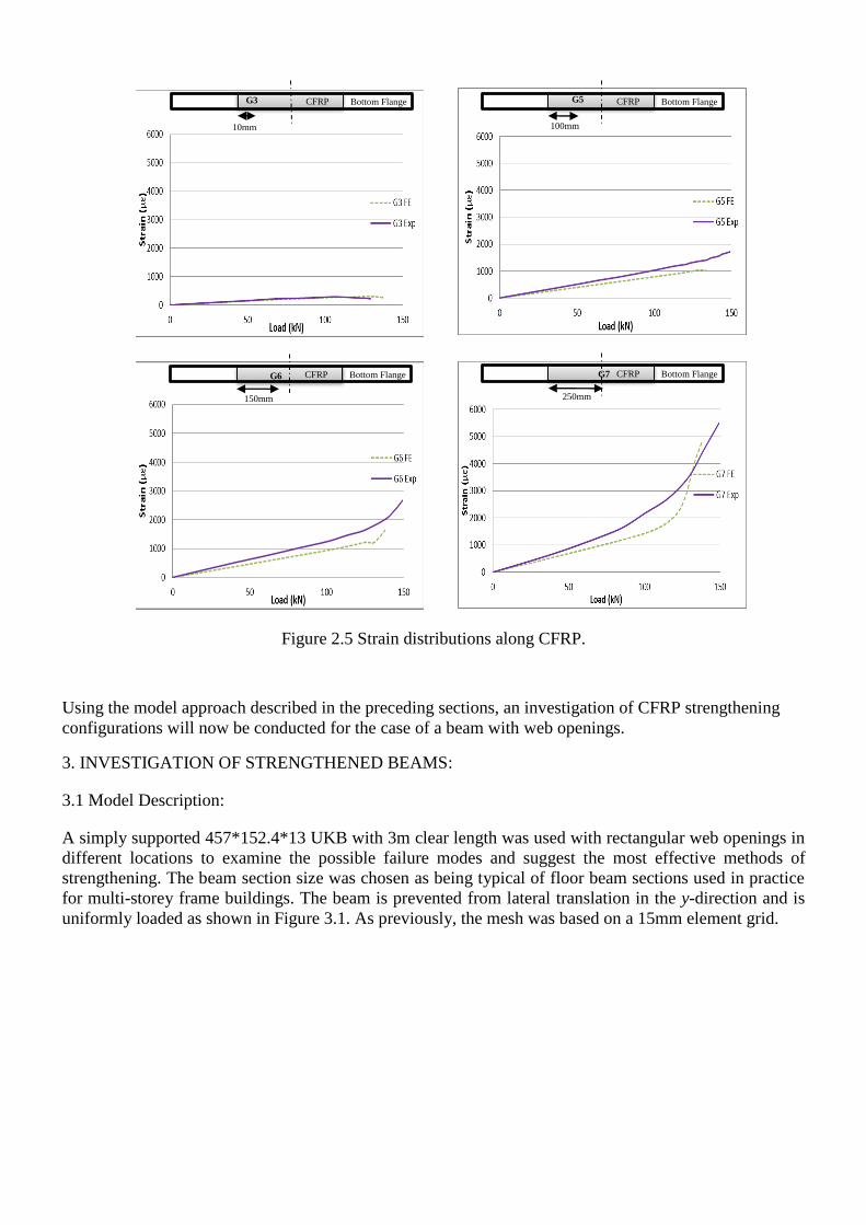
Figure 2.5 Strain distributions along CFRP.
Using the model approach described in the preceding sections, an investigation of CFRP strengthening
configurations will now be conducted for the case of a beam with web openings.
3. INVESTIGATION OF STRENGTHENED BEAMS:
3.1 Model Description:
A simply supported 457*152.4*13 UKB with 3m clear length was used with rectangular web openings in
different locations to examine the possible failure modes and suggest the most effective methods of
strengthening. The beam section size was chosen as being typical of floor beam sections used in practice
for multi-storey frame buildings. The beam is prevented from lateral translation in the y-direction and is
uniformly loaded as shown in Figure 3.1. As previously, the mesh was based on a 15mm element grid.
CFRP
Bottom Flange G3
10mm
CFRP
Bottom Flange G5
100mm
CFRP
Bottom Flange
G6
150mm
CFRP
Bottom Flange
G7
250mm

Figure 3.1 Models description and boundary condition.
3.2 Material properties:
Grade 275 steel was used, which means that the steel has nominal yield strength of 275MPa with the
elastic modulus of 200GPa. The CFRP plates were 25mm wide, and CFRP equal angles were 25*25mm.
The elastic modulus in the fibre direction was 212GPa with 3mm thickness in all cases. Coupled cohesive
behaviour of the adhesive layer with tensile strength (29.7MPa), tensile elastic modulus (8GPa) and shear
modulus (2.6GPa) was adopted.
3.3 Failure modes:
3.3.1Vierendeel Failure:
To simulate this type of failure as shown in Figure 3.2, an opening in the high shear region is introduced.
Transfer of the shear force across the opening causes secondary moments in the tee beam above the
opening. Six different configurations, A to F, using plates, pultrusions or a combination of both have been
modelled to find the most efficient strengthening system. Table 3-1 and Figure 3.3 show the CFRP plate
and angle configurations that have been used for strengthening with, each with the same thickness.
Figure 3.2 Failure mode of beam without strengthening and stress distribution in N/mm2.
UDL
3m
0.6H
0.75H
H
0.6H
0.75H 3m
H
3m
0.6H
0.75H
H
All beams have
been laterally
restrained along
the top flange.
127mm
76mm
4mm
7.6mm
3mm CFRP
plate
Stiffeners
1100mm
500mm
127mm
76mm
4mm
7.6mm
3mm CFRP
plate
Stiffeners
1100mm
500mm
127mm
76mm
4mm
7.6mm
3mm CFRP
plate
Stiffeners
1100mm
500mm
127mm
76mm
4mm
7.6mm
3mm CFRP
plate
Stiffeners
1100mm
500mm
127mm
76mm
4mm
7.6mm
3mm CFRP
plate
Stiffeners
1100mm
500mm
127mm
76mm
4mm
7.6mm
3mm CFRP
plate
Stiffeners
1100mm
500mm
Y
X
Z

Figure 3.3 CFRP locations at opening of the beam.
Table 3-1CFRP configuration for beam with shear opening.
Specimen Description CFRP Length Name Section
CFRP plate strengthening above and
below of opening
4×opening length A
CFRP plate strengthening above and
below of opening, and beneath the top
and bottom flange.
4×opening length B
CFRP plate strengthening above and
below of opening, and beneath the top
and bottom flange.
3×opening length C
CFRP plate strengthening above and
below of opening, and beneath the top
and bottom flange.
2×opening length D
CFRP angle strengthening above and
below of opening.
4×opening length E
CFRP angle strengthening above and
below of opening, and CFRP plate
strengthening beneath the top and
bottom flange.
4×opening length F

The use of these configurations gives different percentages of the strength and stiffness recovery of the
beam after introduction of the opening depending on the strengthening location and strengthening
stiffness as shown in Figure 3.4. Although the specimens B, C and F have different strengthening lengths,
they all obtained a significant strength and stiffness recovery. This was achieved before the first onset of
de-bonding which occurred at a load of 865kN for the horizontal strengthening at top and bottom flanges
and this also coincided with top flange yielding. The specimen F which incorporates angle strengthening
gives the same strength recovery that has been achieved in specimens B and C with plate strengthening,
in all three cases failure was due to debonding at the same load level. However this strength and stiffness
recovery was not observed in other the beams which failed in a brittle manner due to the absence of CFRP
in the top and bottom flanges.
Figure 3.4 Load deflection curve for the steel beam with different configurations of strengthening.
3.3.2 Flexural Failure:
The common failure of this opening location type is due to bending of the tee beam above the web
opening until it becomes fully plastic under pure bending at the middle and ends as shown in Figure 3.5.
Figure 3.5 Failure mode of central opening steel beam and stress distribution in N/mm2.
Figure 3.6 illustrates the load displacement curves of the same configurations in Table 3.1 that have been
utilized to strengthen the steel beam with web opening at mid-span. It can be seen that the configurations
B and F have demonstrated significant strength increases of 20% and 17% respectively more than the
solid beam strength but with different behaviour for both, ductile for B and brittle for F, this is due to the
different CFRP elements in the latter debonding simultaneously. Configuration C which has the same
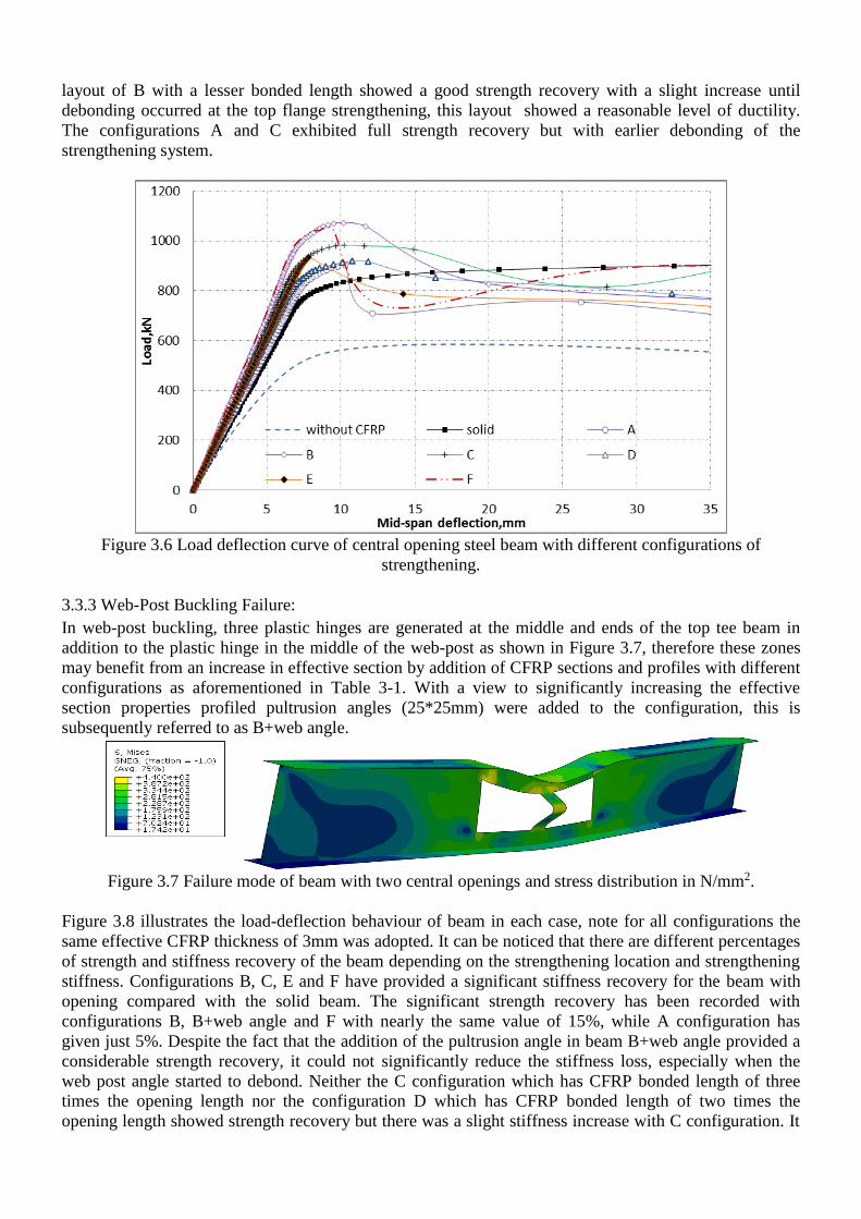
layout of B with a lesser bonded length showed a good strength recovery with a slight increase until
debonding occurred at the top flange strengthening, this layout showed a reasonable level of ductility.
The configurations A and C exhibited full strength recovery but with earlier debonding of the
strengthening system.
Figure 3.6 Load deflection curve of central opening steel beam with different configurations of
strengthening.
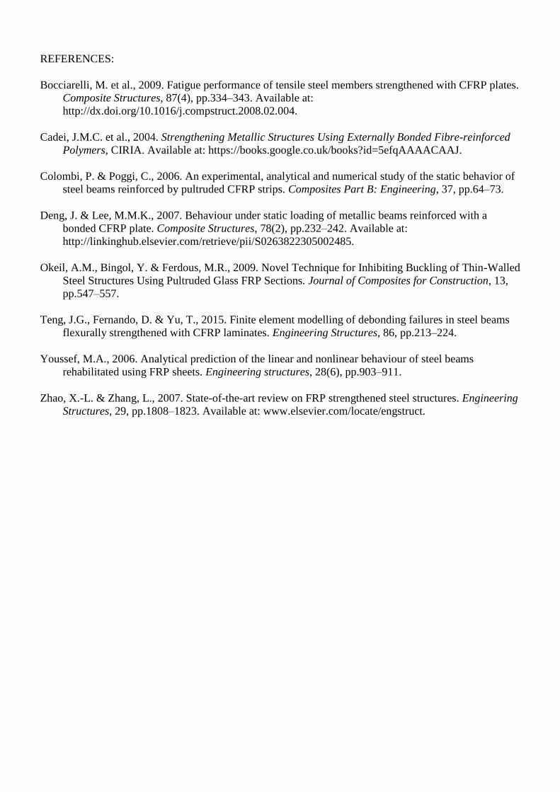
3.3.3 Web-Post Buckling Failure:
In web-post buckling, three plastic hinges are generated at the middle and ends of the top tee beam in
addition to the plastic hinge in the middle of the web-post as shown in Figure 3.7, therefore these zones
may benefit from an increase in effective section by addition of CFRP sections and profiles with different
configurations as aforementioned in Table 3-1. With a view to significantly increasing the effective
section properties profiled pultrusion angles (25*25mm) were added to the configuration, this is
subsequently referred to as B+web angle.
Figure 3.7 Failure mode of beam with two central openings and stress distribution in N/mm2.
Figure 3.8 illustrates the load-deflection behaviour of beam in each case, note for all configurations the
same effective CFRP thickness of 3mm was adopted. It can be noticed that there are different percentages
of strength and stiffness recovery of the beam depending on the strengthening location and strengthening
stiffness. Configurations B, C, E and F have provided a significant stiffness recovery for the beam with
opening compared with the solid beam. The significant strength recovery has been recorded with
configurations B, B+web angle and F with nearly the same value of 15%, while A configuration has
given just 5%. Despite the fact that the addition of the pultrusion angle in beam B+web angle provided a
considerable strength recovery, it could not significantly reduce the stiffness loss, especially when the
web post angle started to debond. Neither the C configuration which has CFRP bonded length of three
times the opening length nor the configuration D which has CFRP bonded length of two times the
opening length showed strength recovery but there was a slight stiffness increase with C configuration. It

is worth mentioning that non-ductile failure is dominant in this type of opening configuration due to the
sudden buckling of the web post.
Figure 3.8 Load deflection curve of beam with two central openings and different configurations of
strengthening.
4. CONCLUSIONS:
The main goal of this project was to investigate the ability of surface bonded CFRP to recover the
strength and stiffness of a steel beam after the introduction of web openings. From this investigation, and
based on the FE results, the following conclusions can be drawn:
1. Strengthening mechanisms using CFRP at both flanges and web with plates or angles are the most
suitable against all the standard failure modes. These configurations give full strength recovery when
used to reinforce the opening at the shear region and load carrying capacity increases of 20% and 15%
were achieved in the cases of bending and web buckling failure respectively.
3. The precise location of the CFRP can often be more critical than length and shape in achieving the
optimum strength effect.
4. Despite the brittle behaviour of the strengthened beams in some cases, CFRP strengthening has the
ability to recover the strength and stiffness of the steel beams especially in the elastic region.
5. It seems intuitive if you add enough CFRP to the beam, you can recover the strength; however in
practical design an economic amount of material to achieve this needs to be arrived at. The need for
strength recovery needs to be balanced with the need to maintain a ductile response from the strengthened
section. As previously outlined, de-bonding often controls the failure of the strengthening rather than
CFRP capacity itself. Optimum layout and efficiency of the strengthening system will be further
explored as part of the ongoing research in this study.
ACKNOWLEDGEMENTS
The authors gratefully acknowledge the contribution of the Iraqi Ministry of Higher Education and the
University of Babylon, Iraq, in funding this research.
REFERENCES:
Bocciarelli, M. et al., 2009. Fatigue performance of tensile steel members strengthened with CFRP plates.
Composite Structures, 87(4), pp.334–343. Available at:
http://dx.doi.org/10.1016/j.compstruct.2008.02.004.
Cadei, J.M.C. et al., 2004. Strengthening Metallic Structures Using Externally Bonded Fibre-reinforced
Polymers, CIRIA. Available at: https://books.google.co.uk/books?id=5efqAAAACAAJ.
Colombi, P. & Poggi, C., 2006. An experimental, analytical and numerical study of the static behavior of
steel beams reinforced by pultruded CFRP strips. Composites Part B: Engineering, 37, pp.64–73.
Deng, J. & Lee, M.M.K., 2007. Behaviour under static loading of metallic beams reinforced with a
bonded CFRP plate. Composite Structures, 78(2), pp.232–242. Available at:
http://linkinghub.elsevier.com/retrieve/pii/S0263822305002485.
Okeil, A.M., Bingol, Y. & Ferdous, M.R., 2009. Novel Technique for Inhibiting Buckling of Thin-Walled
Steel Structures Using Pultruded Glass FRP Sections. Journal of Composites for Construction, 13,
pp.547–557.
Teng, J.G., Fernando, D. & Yu, T., 2015. Finite element modelling of debonding failures in steel beams
flexurally strengthened with CFRP laminates. Engineering Structures, 86, pp.213–224.
Youssef, M.A., 2006. Analytical prediction of the linear and nonlinear behaviour of steel beams
rehabilitated using FRP sheets. Engineering structures, 28(6), pp.903–911.
Zhao, X.-L. & Zhang, L., 2007. State-of-the-art review on FRP strengthened steel structures. Engineering
Structures, 29, pp.1808–1823. Available at: www.elsevier.com/locate/engstruct.