CHAPTER 6 AXIAL STRENGTHENING USING CFRP...
57
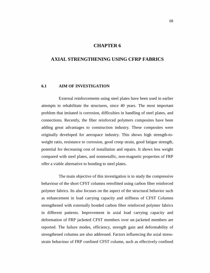
68 CHAPTER 6 AXIAL STRENGTHENING USING CFRP FABRICS 6.1 AIM OF INVESTIGATION External reinforcements using steel plates have been used in earlier attempts to rehabilitate the structures, since 40 years. The most important problem that imitated is corrosion, difficulties in handling of steel plates, and connections. Recently, the fiber reinforced polymers composites have been adding great advantages to construction industry. These composites were originally developed for aerospace industry. This shows high strength-to- weight ratio, resistance to corrosion, good creep strain, good fatigue strength, potential for decreasing cost of installation and repairs. It shows less weight compared with steel plates, and nonmetallic, non-magnetic properties of FRP offer a viable alternative to bonding to steel plates. The main objective of this investigation is to study the compressive behaviour of the short CFST columns retrofitted using carbon fiber reinforced polymer fabrics. Its also focuses on the aspect of the structural behavior such as enhancement in load carrying capacity and stiffness of CFST Columns strengthened with externally bonded carbon fiber reinforced polymer fabrics in different patterns. Improvement in axial load carrying capacity and deformation of FRP jacketed CFST members over un-jacketed members are reported. The failure modes, efficiency, strength gain and deformability of strengthened columns are also addressed. Factors influencing the axial stress- strain behaviour of FRP confined CFST column, such as effectively confined
Transcript of CHAPTER 6 AXIAL STRENGTHENING USING CFRP...
68
CHAPTER 6
AXIAL STRENGTHENING USING CFRP FABRICS
6.1 AIM OF INVESTIGATION
External reinforcements using steel plates have been used in earlier
attempts to rehabilitate the structures, since 40 years. The most important
problem that imitated is corrosion, difficulties in handling of steel plates, and
connections. Recently, the fiber reinforced polymers composites have been
adding great advantages to construction industry. These composites were
originally developed for aerospace industry. This shows high strength-to-
weight ratio, resistance to corrosion, good creep strain, good fatigue strength,
potential for decreasing cost of installation and repairs. It shows less weight
compared with steel plates, and nonmetallic, non-magnetic properties of FRP
offer a viable alternative to bonding to steel plates.
The main objective of this investigation is to study the compressive
behaviour of the short CFST columns retrofitted using carbon fiber reinforced
polymer fabrics. Its also focuses on the aspect of the structural behavior such
as enhancement in load carrying capacity and stiffness of CFST Columns
strengthened with externally bonded carbon fiber reinforced polymer fabrics
in different patterns. Improvement in axial load carrying capacity and
deformation of FRP jacketed CFST members over un-jacketed members are
reported. The failure modes, efficiency, strength gain and deformability of
strengthened columns are also addressed. Factors influencing the axial stress-
strain behaviour of FRP confined CFST column, such as effectively confined
69
regions and their relationship to jacket properties are identified and discussed.
Further, this work presents a simple comparative study between the
compression members strengthened with carbon fiber reinforced polymer
fabrics as well as the control members.
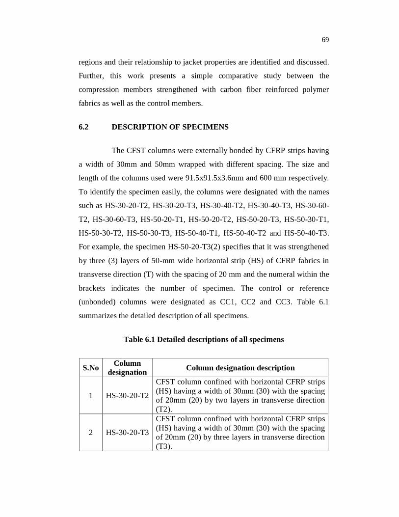
6.2 DESCRIPTION OF SPECIMENS
The CFST columns were externally bonded by CFRP strips having
a width of 30mm and 50mm wrapped with different spacing. The size and
length of the columns used were 91.5x91.5x3.6mm and 600 mm respectively.
To identify the specimen easily, the columns were designated with the names
such as HS-30-20-T2, HS-30-20-T3, HS-30-40-T2, HS-30-40-T3, HS-30-60-
T2, HS-30-60-T3, HS-50-20-T1, HS-50-20-T2, HS-50-20-T3, HS-50-30-T1,
HS-50-30-T2, HS-50-30-T3, HS-50-40-T1, HS-50-40-T2 and HS-50-40-T3.
For example, the specimen HS-50-20-T3(2) specifies that it was strengthened
by three (3) layers of 50-mm wide horizontal strip (HS) of CFRP fabrics in
transverse direction (T) with the spacing of 20 mm and the numeral within the
brackets indicates the number of specimen. The control or reference
(unbonded) columns were designated as CC1, CC2 and CC3. Table 6.1
summarizes the detailed description of all specimens.
Table 6.1 Detailed descriptions of all specimens
S.No Column designation Column designation description
1 HS-30-20-T2
CFST column confined with horizontal CFRP strips (HS) having a width of 30mm (30) with the spacing of 20mm (20) by two layers in transverse direction (T2).
2 HS-30-20-T3
CFST column confined with horizontal CFRP strips (HS) having a width of 30mm (30) with the spacing of 20mm (20) by three layers in transverse direction (T3).
70
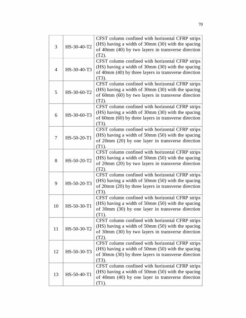
3 HS-30-40-T2
CFST column confined with horizontal CFRP strips (HS) having a width of 30mm (30) with the spacing of 40mm (40) by two layers in transverse direction (T2).
4 HS-30-40-T3
CFST column confined with horizontal CFRP strips (HS) having a width of 30mm (30) with the spacing of 40mm (40) by three layers in transverse direction (T3).
5 HS-30-60-T2
CFST column confined with horizontal CFRP strips (HS) having a width of 30mm (30) with the spacing of 60mm (60) by two layers in transverse direction (T2).
6 HS-30-60-T3
CFST column confined with horizontal CFRP strips (HS) having a width of 30mm (30) with the spacing of 60mm (60) by three layers in transverse direction (T3).
7 HS-50-20-T1
CFST column confined with horizontal CFRP strips (HS) having a width of 50mm (50) with the spacing of 20mm (20) by one layer in transverse direction (T1).
8 HS-50-20-T2
CFST column confined with horizontal CFRP strips (HS) having a width of 50mm (50) with the spacing of 20mm (20) by two layers in transverse direction (T2).
9 HS-50-20-T3
CFST column confined with horizontal CFRP strips (HS) having a width of 50mm (50) with the spacing of 20mm (20) by three layers in transverse direction (T3).
10 HS-50-30-T1
CFST column confined with horizontal CFRP strips (HS) having a width of 50mm (50) with the spacing of 30mm (30) by one layer in transverse direction (T1).
11 HS-50-30-T2
CFST column confined with horizontal CFRP strips (HS) having a width of 50mm (50) with the spacing of 30mm (30) by two layers in transverse direction (T2).
12 HS-50-30-T3
CFST column confined with horizontal CFRP strips (HS) having a width of 50mm (50) with the spacing of 30mm (30) by three layers in transverse direction (T3).
13 HS-50-40-T1
CFST column confined with horizontal CFRP strips (HS) having a width of 50mm (50) with the spacing of 40mm (40) by one layer in transverse direction (T1).
71
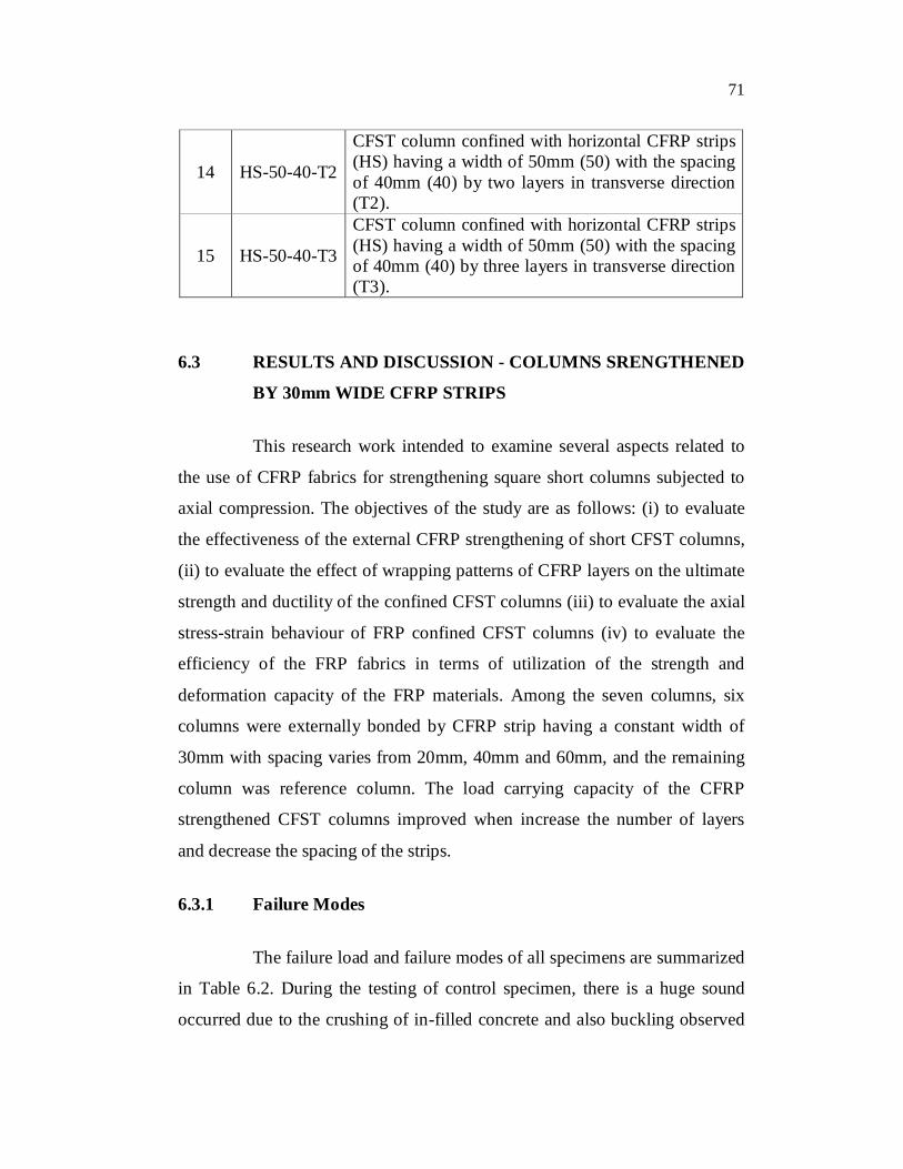
14 HS-50-40-T2
CFST column confined with horizontal CFRP strips (HS) having a width of 50mm (50) with the spacing of 40mm (40) by two layers in transverse direction (T2).
15 HS-50-40-T3
CFST column confined with horizontal CFRP strips (HS) having a width of 50mm (50) with the spacing of 40mm (40) by three layers in transverse direction (T3).
6.3 RESULTS AND DISCUSSION - COLUMNS SRENGTHENED
BY 30mm WIDE CFRP STRIPS
This research work intended to examine several aspects related to
the use of CFRP fabrics for strengthening square short columns subjected to
axial compression. The objectives of the study are as follows: (i) to evaluate
the effectiveness of the external CFRP strengthening of short CFST columns,
(ii) to evaluate the effect of wrapping patterns of CFRP layers on the ultimate
strength and ductility of the confined CFST columns (iii) to evaluate the axial
stress-strain behaviour of FRP confined CFST columns (iv) to evaluate the
efficiency of the FRP fabrics in terms of utilization of the strength and
deformation capacity of the FRP materials. Among the seven columns, six
columns were externally bonded by CFRP strip having a constant width of
30mm with spacing varies from 20mm, 40mm and 60mm, and the remaining
column was reference column. The load carrying capacity of the CFRP
strengthened CFST columns improved when increase the number of layers
and decrease the spacing of the strips.
6.3.1 Failure Modes
The failure load and failure modes of all specimens are summarized
in Table 6.2. During the testing of control specimen, there is a huge sound
occurred due to the crushing of in-filled concrete and also buckling observed
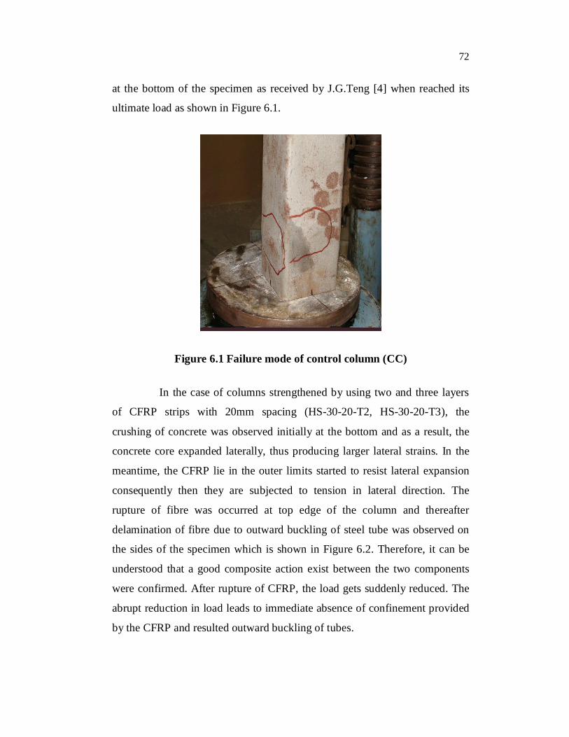
72
at the bottom of the specimen as received by J.G.Teng [4] when reached its
ultimate load as shown in Figure 6.1.
Figure 6.1 Failure mode of control column (CC)
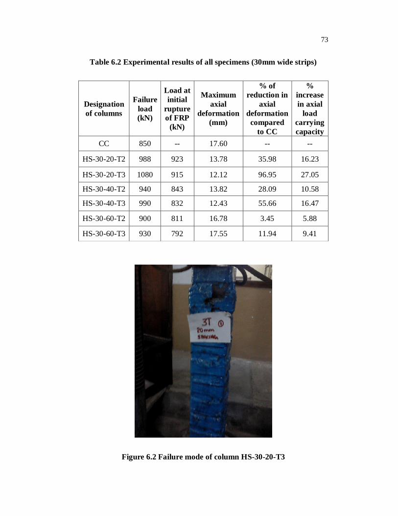
In the case of columns strengthened by using two and three layers
of CFRP strips with 20mm spacing (HS-30-20-T2, HS-30-20-T3), the
crushing of concrete was observed initially at the bottom and as a result, the
concrete core expanded laterally, thus producing larger lateral strains. In the
meantime, the CFRP lie in the outer limits started to resist lateral expansion
consequently then they are subjected to tension in lateral direction. The
rupture of fibre was occurred at top edge of the column and thereafter
delamination of fibre due to outward buckling of steel tube was observed on
the sides of the specimen which is shown in Figure 6.2. Therefore, it can be
understood that a good composite action exist between the two components
were confirmed. After rupture of CFRP, the load gets suddenly reduced. The
abrupt reduction in load leads to immediate absence of confinement provided
by the CFRP and resulted outward buckling of tubes.
73
Table 6.2 Experimental results of all specimens (30mm wide strips)
Designation of columns
Failure load (kN)
Load at initial
rupture of FRP
(kN)
Maximum axial
deformation (mm)
% of reduction in
axial deformation
compared to CC
% increase in axial
load carrying capacity
CC 850 -- 17.60 -- --
HS-30-20-T2 988 923 13.78 35.98 16.23
HS-30-20-T3 1080 915 12.12 96.95 27.05
HS-30-40-T2 940 843 13.82 28.09 10.58
HS-30-40-T3 990 832 12.43 55.66 16.47
HS-30-60-T2 900 811 16.78 3.45 5.88
HS-30-60-T3 930 792 17.55 11.94 9.41
Figure 6.2 Failure mode of column HS-30-20-T3
74
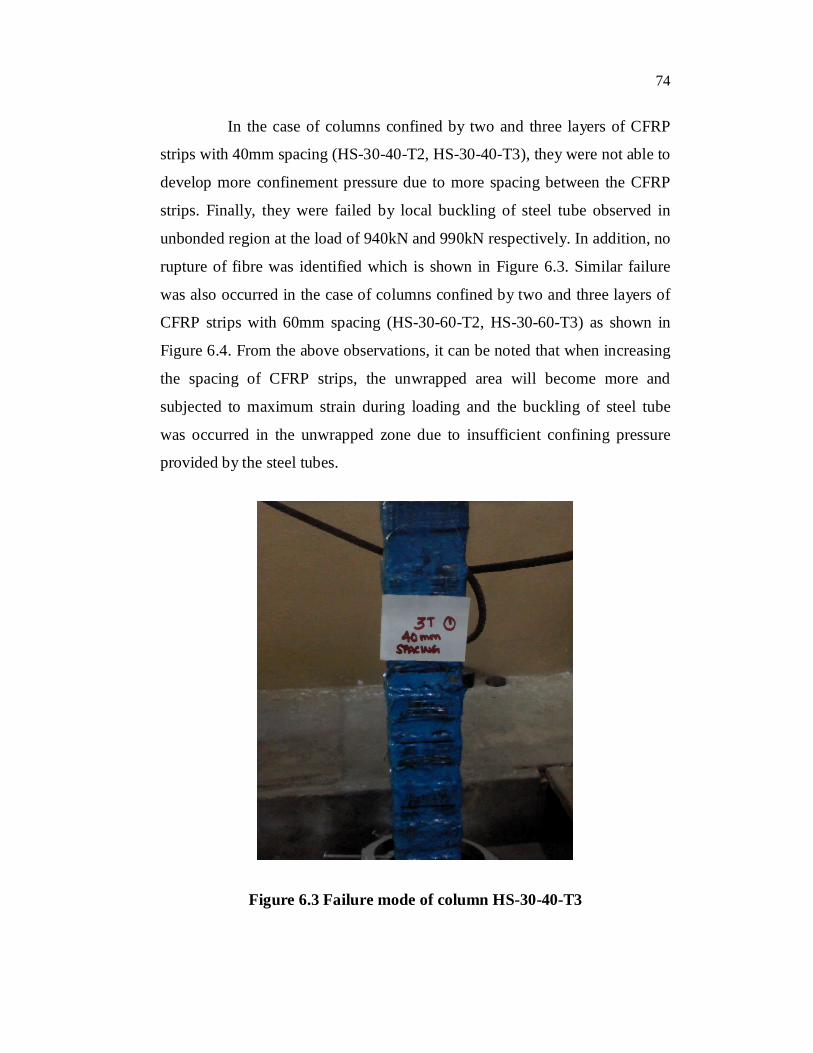
In the case of columns confined by two and three layers of CFRP
strips with 40mm spacing (HS-30-40-T2, HS-30-40-T3), they were not able to
develop more confinement pressure due to more spacing between the CFRP
strips. Finally, they were failed by local buckling of steel tube observed in
unbonded region at the load of 940kN and 990kN respectively. In addition, no
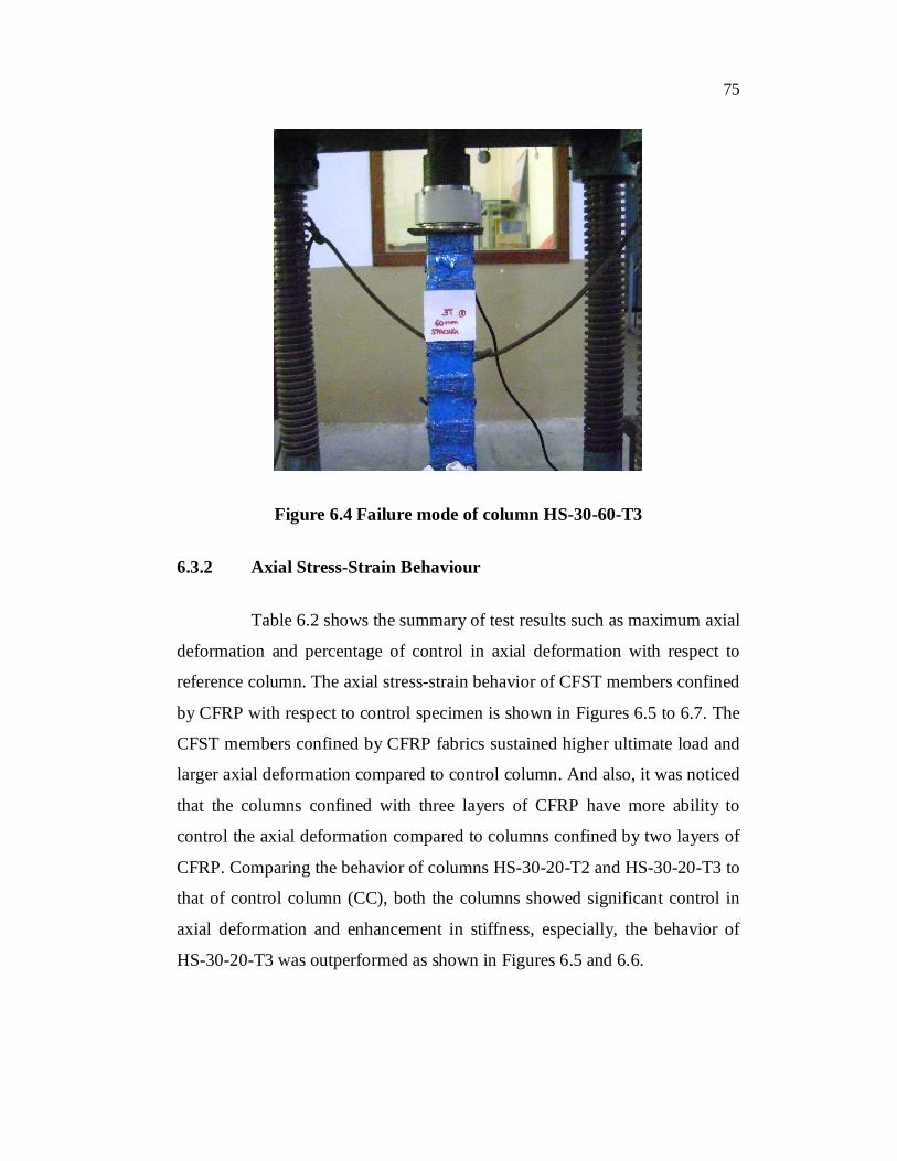
rupture of fibre was identified which is shown in Figure 6.3. Similar failure
was also occurred in the case of columns confined by two and three layers of
CFRP strips with 60mm spacing (HS-30-60-T2, HS-30-60-T3) as shown in
Figure 6.4. From the above observations, it can be noted that when increasing
the spacing of CFRP strips, the unwrapped area will become more and
subjected to maximum strain during loading and the buckling of steel tube
was occurred in the unwrapped zone due to insufficient confining pressure
provided by the steel tubes.
Figure 6.3 Failure mode of column HS-30-40-T3
75
Figure 6.4 Failure mode of column HS-30-60-T3
6.3.2 Axial Stress-Strain Behaviour
Table 6.2 shows the summary of test results such as maximum axial
deformation and percentage of control in axial deformation with respect to
reference column. The axial stress-strain behavior of CFST members confined
by CFRP with respect to control specimen is shown in Figures 6.5 to 6.7. The
CFST members confined by CFRP fabrics sustained higher ultimate load and
larger axial deformation compared to control column. And also, it was noticed
that the columns confined with three layers of CFRP have more ability to
control the axial deformation compared to columns confined by two layers of
CFRP. Comparing the behavior of columns HS-30-20-T2 and HS-30-20-T3 to
that of control column (CC), both the columns showed significant control in
axial deformation and enhancement in stiffness, especially, the behavior of
HS-30-20-T3 was outperformed as shown in Figures 6.5 and 6.6.
76
0
20
40
60
80
100
120
0.000 0.005 0.010 0.015 0.020 0.025 0.030 0.035
Axial strain
Axi
al st
ress
(N/m
m2 )
CC HS-30-20-T2
HS-30-40-T2 HS-30-60-T2
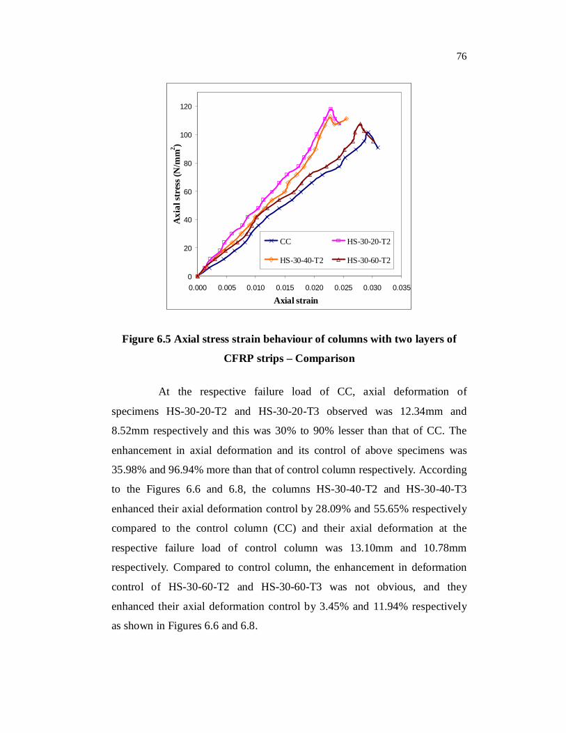
Figure 6.5 Axial stress strain behaviour of columns with two layers of
CFRP strips – Comparison
At the respective failure load of CC, axial deformation of
specimens HS-30-20-T2 and HS-30-20-T3 observed was 12.34mm and
8.52mm respectively and this was 30% to 90% lesser than that of CC. The
enhancement in axial deformation and its control of above specimens was
35.98% and 96.94% more than that of control column respectively. According
to the Figures 6.6 and 6.8, the columns HS-30-40-T2 and HS-30-40-T3
enhanced their axial deformation control by 28.09% and 55.65% respectively
compared to the control column (CC) and their axial deformation at the
respective failure load of control column was 13.10mm and 10.78mm
respectively. Compared to control column, the enhancement in deformation
control of HS-30-60-T2 and HS-30-60-T3 was not obvious, and they
enhanced their axial deformation control by 3.45% and 11.94% respectively
as shown in Figures 6.6 and 6.8.
77
0
20
40
60
80
100
120
0.000 0.005 0.010 0.015 0.020 0.025 0.030 0.035
Axial strain
Axi
al st
ress
(N/m
m2 )
CC HS-30-20-T3
HS-30-40-T3 HS-30-60-T3
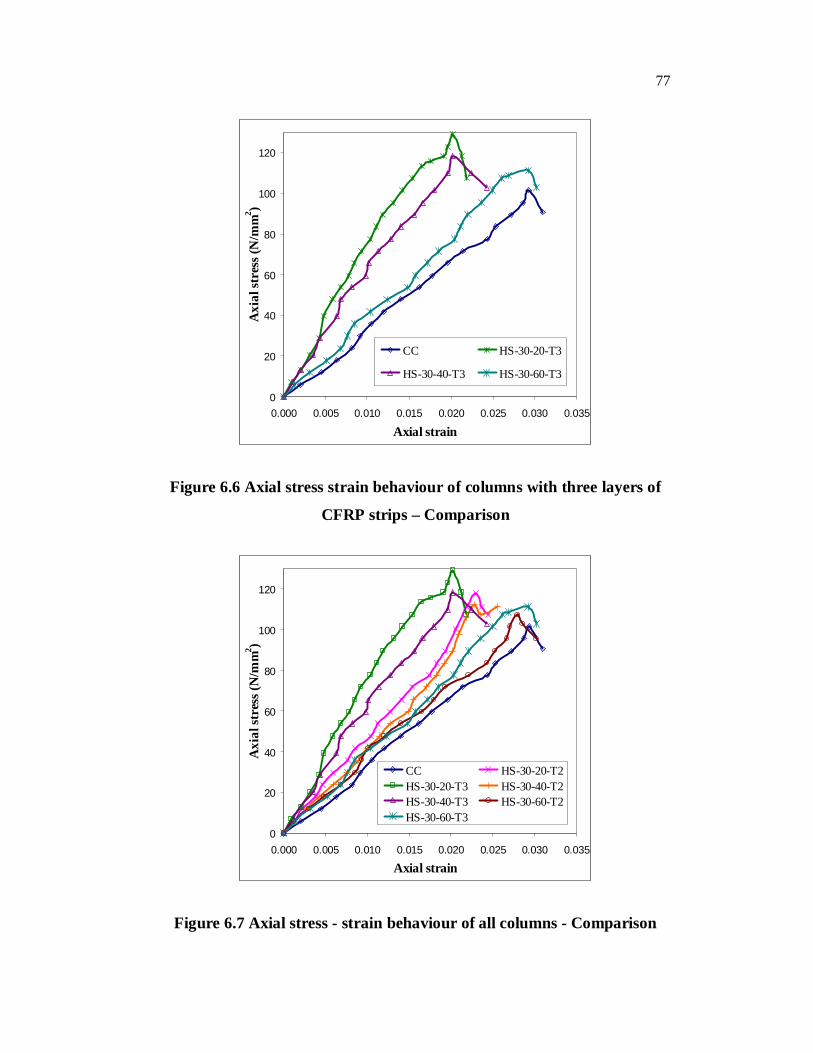
Figure 6.6 Axial stress strain behaviour of columns with three layers of
CFRP strips – Comparison
0
20
40
60
80
100
120
0.000 0.005 0.010 0.015 0.020 0.025 0.030 0.035
Axial strain
Axi
al st
ress
(N/m
m2 )
CC HS-30-20-T2HS-30-20-T3 HS-30-40-T2HS-30-40-T3 HS-30-60-T2HS-30-60-T3
Figure 6.7 Axial stress - strain behaviour of all columns - Comparison
78
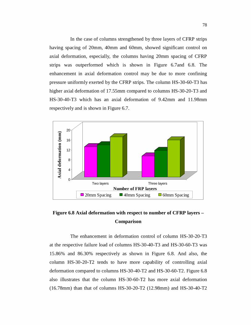
In the case of columns strengthened by three layers of CFRP strips
having spacing of 20mm, 40mm and 60mm, showed significant control on
axial deformation, especially, the columns having 20mm spacing of CFRP
strips was outperformed which is shown in Figure 6.7and 6.8. The
enhancement in axial deformation control may be due to more confining
pressure uniformly exerted by the CFRP strips. The column HS-30-60-T3 has
higher axial deformation of 17.55mm compared to columns HS-30-20-T3 and
HS-30-40-T3 which has an axial deformation of 9.42mm and 11.98mm
respectively and is shown in Figure 6.7.
0
4
8
12
16
20
Axi
al d
efor
mat
ion
(mm
)
Two layers Three layersNumber of FRP layers
20mm Spacing 40mm Spacing 60mm Spacing
Figure 6.8 Axial deformation with respect to number of CFRP layers –
Comparison
The enhancement in deformation control of column HS-30-20-T3
at the respective failure load of columns HS-30-40-T3 and HS-30-60-T3 was
15.86% and 86.30% respectively as shown in Figure 6.8. And also, the
column HS-30-20-T2 tends to have more capability of controlling axial
deformation compared to columns HS-30-40-T2 and HS-30-60-T2. Figure 6.8
also illustrates that the column HS-30-60-T2 has more axial deformation
(16.78mm) than that of columns HS-30-20-T2 (12.98mm) and HS-30-40-T2
79
(14.13mm). In overall, the columns strengthened by 30mm CFRP strips
having a spacing of 20mm, effectively control the axial deformation
compared to the column strengthened by same width of CFRP strips having a
spacing of 40mm and 60mm.
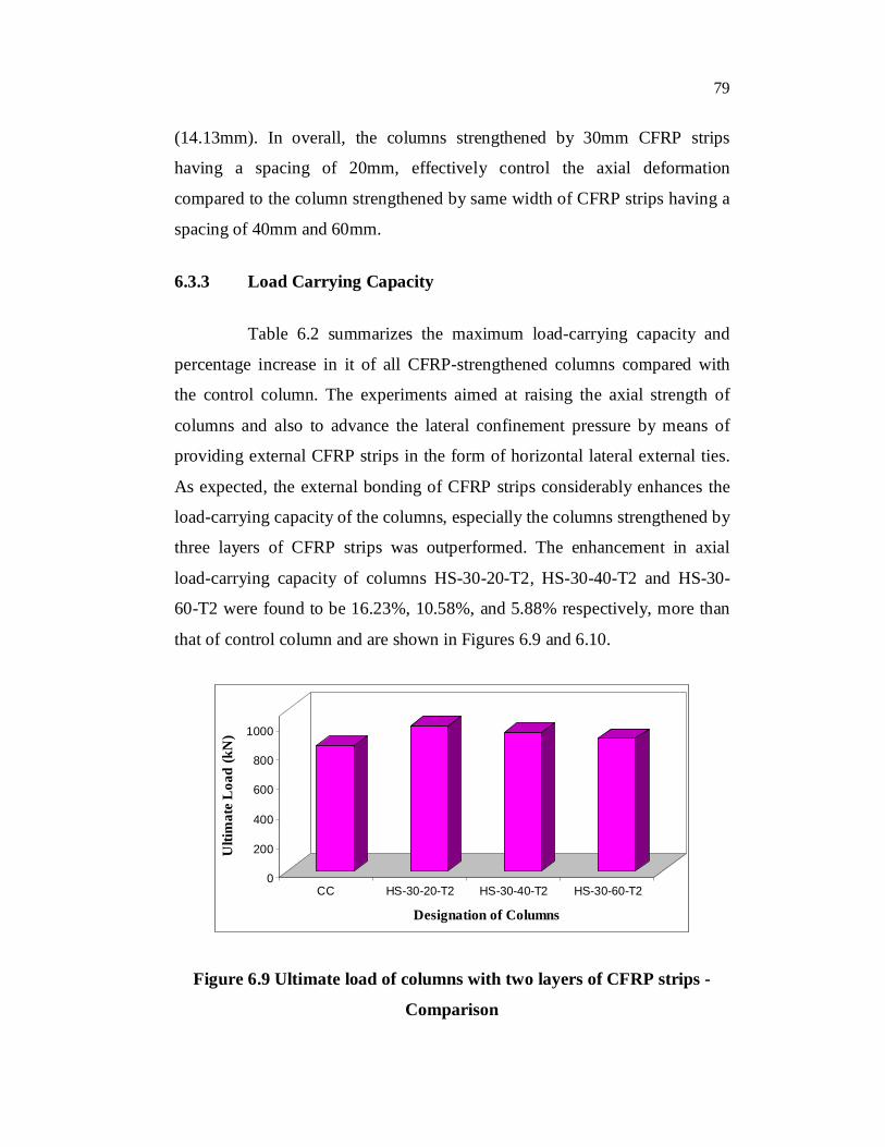
6.3.3 Load Carrying Capacity
Table 6.2 summarizes the maximum load-carrying capacity and
percentage increase in it of all CFRP-strengthened columns compared with
the control column. The experiments aimed at raising the axial strength of
columns and also to advance the lateral confinement pressure by means of
providing external CFRP strips in the form of horizontal lateral external ties.
As expected, the external bonding of CFRP strips considerably enhances the
load-carrying capacity of the columns, especially the columns strengthened by
three layers of CFRP strips was outperformed. The enhancement in axial
load-carrying capacity of columns HS-30-20-T2, HS-30-40-T2 and HS-30-
60-T2 were found to be 16.23%, 10.58%, and 5.88% respectively, more than
that of control column and are shown in Figures 6.9 and 6.10.
0
200
400
600
800
1000
Ulti
mat
e L
oad
(kN
)
CC HS-30-20-T2 HS-30-40-T2 HS-30-60-T2
Designation of Columns
Figure 6.9 Ultimate load of columns with two layers of CFRP strips -
Comparison
80
0
200
400
600
800
1000
Ulti
mat
e L
oad
(kN
)
CC HS-30-20-T3 HS-30-40-T3 HS-30-60-T3
Designation of Columns
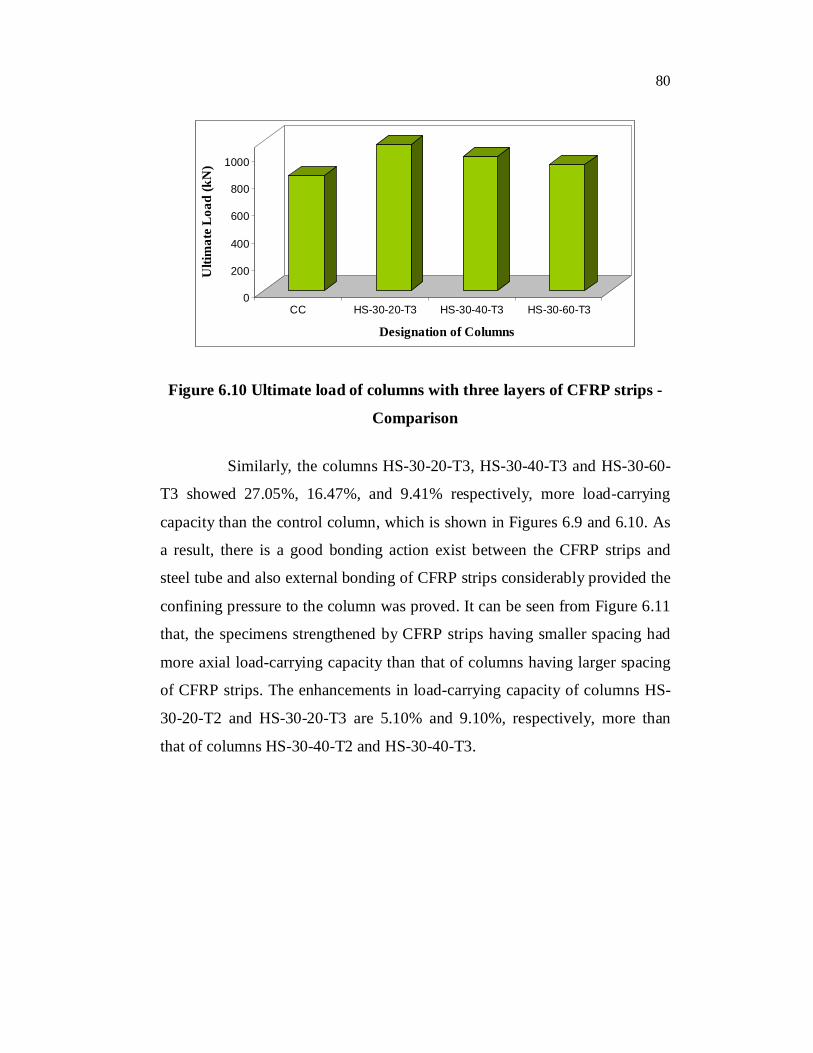
Figure 6.10 Ultimate load of columns with three layers of CFRP strips -
Comparison
Similarly, the columns HS-30-20-T3, HS-30-40-T3 and HS-30-60-
T3 showed 27.05%, 16.47%, and 9.41% respectively, more load-carrying
capacity than the control column, which is shown in Figures 6.9 and 6.10. As
a result, there is a good bonding action exist between the CFRP strips and
steel tube and also external bonding of CFRP strips considerably provided the
confining pressure to the column was proved. It can be seen from Figure 6.11
that, the specimens strengthened by CFRP strips having smaller spacing had
more axial load-carrying capacity than that of columns having larger spacing
of CFRP strips. The enhancements in load-carrying capacity of columns HS-
30-20-T2 and HS-30-20-T3 are 5.10% and 9.10%, respectively, more than
that of columns HS-30-40-T2 and HS-30-40-T3.
81
0
200
400
600
800
1000
Ulti
mat
e L
oad
(kN
)
Two layers Three layers
Number of FRP layers20mm spacing 40mm spacing 60mm spacing
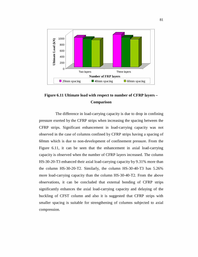
Figure 6.11 Ultimate load with respect to number of CFRP layers –
Comparison
The difference in load-carrying capacity is due to drop in confining
pressure exerted by the CFRP strips when increasing the spacing between the
CFRP strips. Significant enhancement in load-carrying capacity was not
observed in the case of columns confined by CFRP strips having a spacing of
60mm which is due to non-development of confinement pressure. From the
Figure 6.11, it can be seen that the enhancement in axial load-carrying
capacity is observed when the number of CFRP layers increased. The column
HS-30-20-T3 enhanced their axial load-carrying capacity by 9.31% more than
the column HS-30-20-T2. Similarly, the column HS-30-40-T3 has 5.26%
more load-carrying capacity than the column HS-30-40-T2. From the above
observations, it can be concluded that external bonding of CFRP strips
significantly enhances the axial load-carrying capacity and delaying of the
buckling of CFST column and also it is suggested that CFRP strips with
smaller spacing is suitable for strengthening of columns subjected to axial
compression.
82
6.4 RESULTS AND DISCUSSION- COLUMN STRENGTHENED
BY 50mm WIDE CFRP STRIPS
Out of 30 columns, 27 columns were externally bonded by CFRP
strips having a constant width of 50mm with the spacing of 20mm, 30mm and
40mm and the remaining three specimens were reference columns. The test
results of the specimens strengthened by 50mm strips are as follows.
6.4.1 Failure Modes
The columns were tested until failure to understand the influence of
carbon fibre fabrics on the axial behavior of CFST members. The summary of
test results such as failure load and load at initial rupture are given in Table
6.3. Until reach a load of 850kN on jack, linear response was observed in all
unwrapped specimens and thereafter non-linear response was observed.
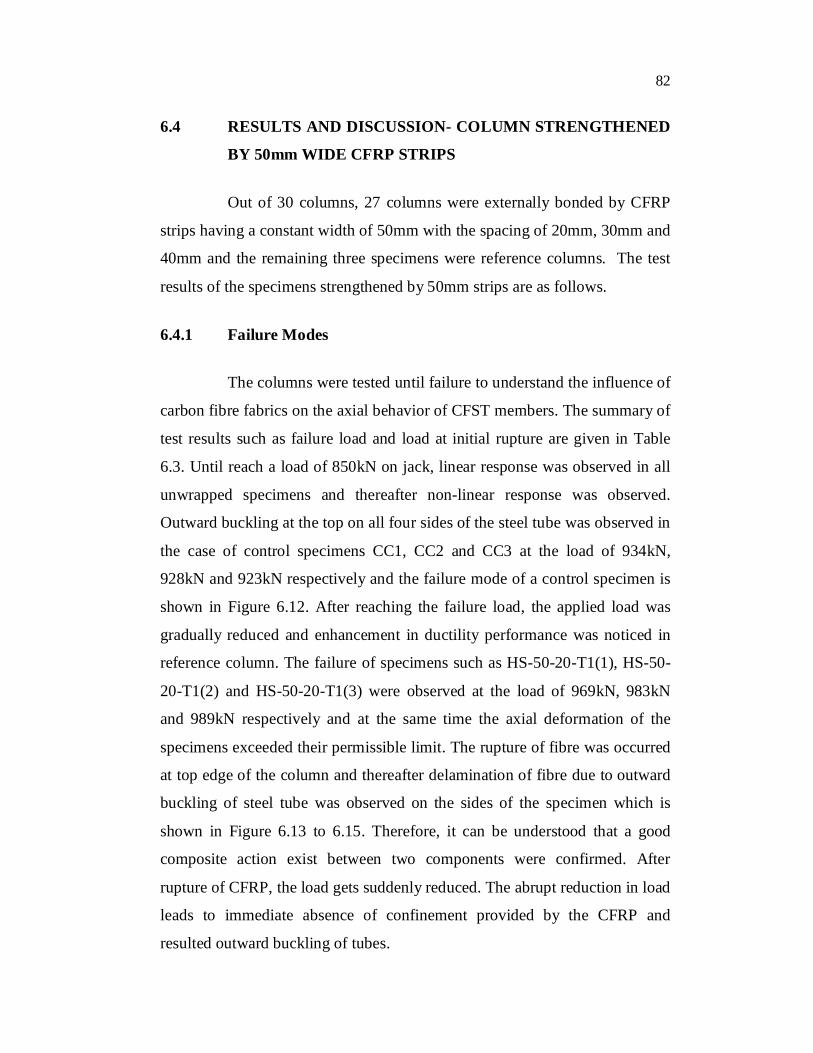
Outward buckling at the top on all four sides of the steel tube was observed in
the case of control specimens CC1, CC2 and CC3 at the load of 934kN,
928kN and 923kN respectively and the failure mode of a control specimen is
shown in Figure 6.12. After reaching the failure load, the applied load was
gradually reduced and enhancement in ductility performance was noticed in
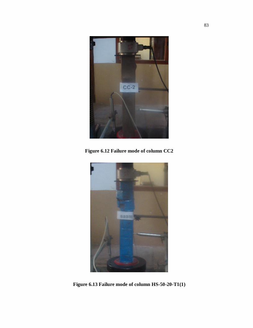
reference column. The failure of specimens such as HS-50-20-T1(1), HS-50-
20-T1(2) and HS-50-20-T1(3) were observed at the load of 969kN, 983kN
and 989kN respectively and at the same time the axial deformation of the
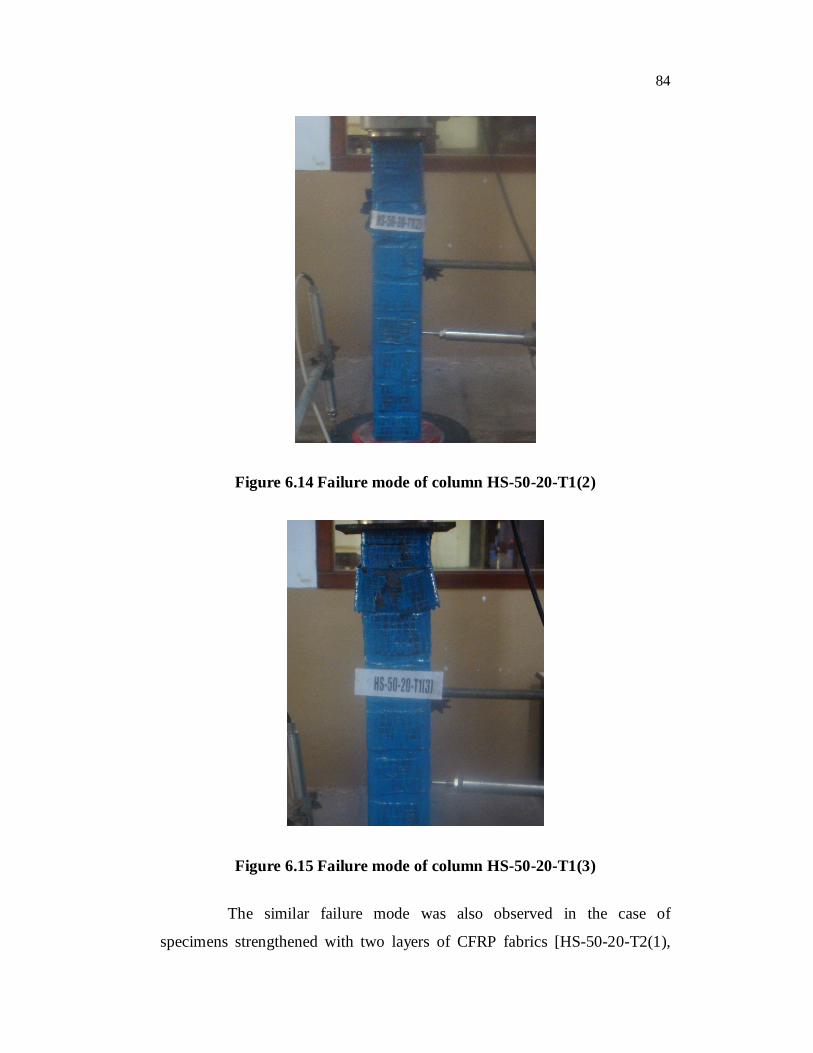
specimens exceeded their permissible limit. The rupture of fibre was occurred
at top edge of the column and thereafter delamination of fibre due to outward
buckling of steel tube was observed on the sides of the specimen which is
shown in Figure 6.13 to 6.15. Therefore, it can be understood that a good
composite action exist between two components were confirmed. After
rupture of CFRP, the load gets suddenly reduced. The abrupt reduction in load
leads to immediate absence of confinement provided by the CFRP and
resulted outward buckling of tubes.
83
Figure 6.12 Failure mode of column CC2
Figure 6.13 Failure mode of column HS-50-20-T1(1)
84
Figure 6.14 Failure mode of column HS-50-20-T1(2)
Figure 6.15 Failure mode of column HS-50-20-T1(3)
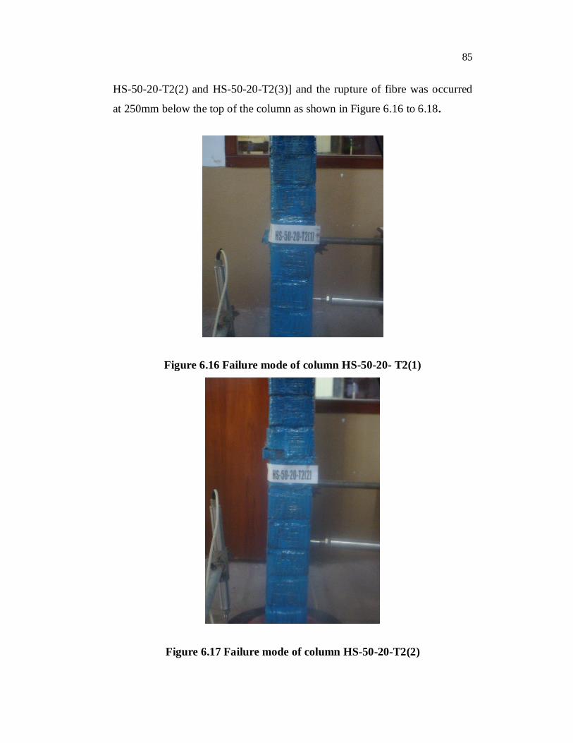
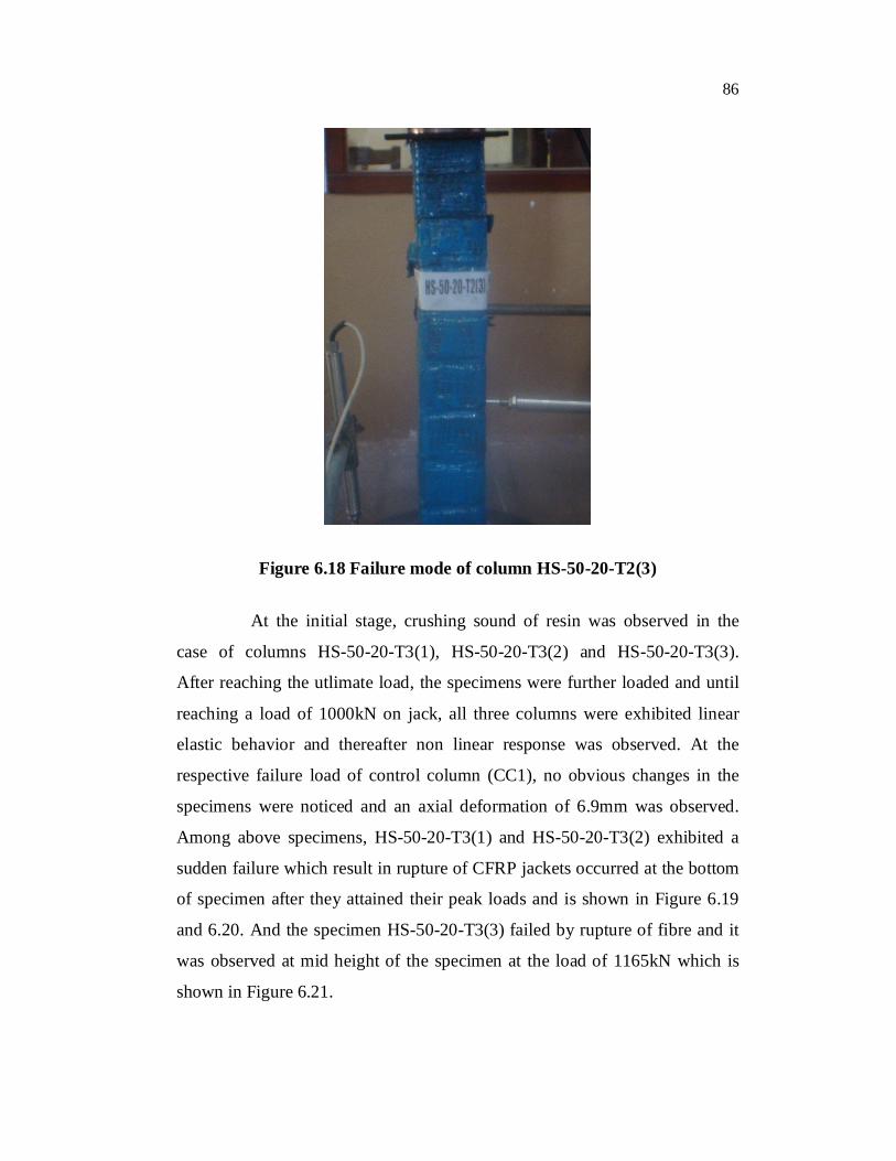
The similar failure mode was also observed in the case of
specimens strengthened with two layers of CFRP fabrics [HS-50-20-T2(1),
85
HS-50-20-T2(2) and HS-50-20-T2(3)] and the rupture of fibre was occurred
at 250mm below the top of the column as shown in Figure 6.16 to 6.18.
Figure 6.16 Failure mode of column HS-50-20- T2(1)
Figure 6.17 Failure mode of column HS-50-20-T2(2)
86
Figure 6.18 Failure mode of column HS-50-20-T2(3)
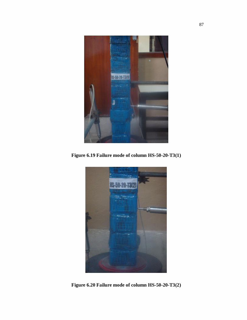
At the initial stage, crushing sound of resin was observed in the
case of columns HS-50-20-T3(1), HS-50-20-T3(2) and HS-50-20-T3(3).
After reaching the utlimate load, the specimens were further loaded and until
reaching a load of 1000kN on jack, all three columns were exhibited linear
elastic behavior and thereafter non linear response was observed. At the
respective failure load of control column (CC1), no obvious changes in the
specimens were noticed and an axial deformation of 6.9mm was observed.
Among above specimens, HS-50-20-T3(1) and HS-50-20-T3(2) exhibited a
sudden failure which result in rupture of CFRP jackets occurred at the bottom
of specimen after they attained their peak loads and is shown in Figure 6.19
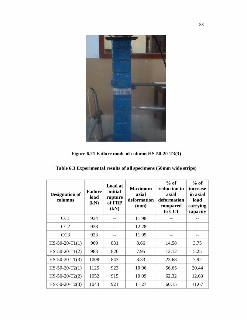
and 6.20. And the specimen HS-50-20-T3(3) failed by rupture of fibre and it
was observed at mid height of the specimen at the load of 1165kN which is
shown in Figure 6.21.
87
Figure 6.19 Failure mode of column HS-50-20-T3(1)
Figure 6.20 Failure mode of column HS-50-20-T3(2)
88
Figure 6.21 Failure mode of column HS-50-20-T3(3)
Table 6.3 Experimental results of all specimens (50mm wide strips)
Designation of columns
Failure load (kN)
Load at initial
rupture of FRP
(kN)
Maximum axial
deformation (mm)
% of reduction in
axial deformation compared
to CC1
% of increase in axial
load carrying capacity
CC1 934 -- 11.98 -- --
CC2 928 -- 12.28 -- --
CC3 923 -- 11.99 -- --
HS-50-20-T1(1) 969 831 8.66 14.58 3.75
HS-50-20-T1(2) 983 826 7.95 12.12 5.25
HS-50-20-T1(3) 1008 843 8.33 23.68 7.92
HS-50-20-T2(1) 1125 923 10.96 56.65 20.44
HS-50-20-T2(2) 1052 915 10.09 62.32 12.63
HS-50-20-T2(3) 1043 921 11.27 60.15 11.67
89
HS-50-20-T3(1) 1145 943 13.17 92.05 22.51
HS-50-20-T3(2) 1160 904 11.70 91.50 24.19
HS-50-20-T3(3) 1202 932 10.29 85.05 28.69
HS-50-30-T1(1) 965 823 9.94 22.11 3.32
HS-50-30-T1(2) 991 820 8.79 19.58 6.10
HS-50-30-T1(3) 1001 882 10.01 25.12 7.17
HS-50-30-T2(1) 1070 904 11.60 34.11 14.56
HS-50-30-T2(2) 1022 934 11.89 42.12 9.42
HS-50-30-T2(3) 1066 941 12.14 41.15 14.13
HS-50-30-T3(1) 1122 928 11.23 50.01 20.12
HS-50-30-T3(2) 1200 934 11.79 66.24 28.48
HS-50-30-T3(3) 1105 918 12.12 50.12 18.31
HS-50-40-T1(1) 956 836 9.73 5.88 2.43
HS-50-40-T1(2) 972 834 9.76 7.21 4.12
HS-50-40-T1(3) 989 846 9.98 13.08 5.88
HS-50-40-T2(1) 1033 912 10.87 50.16 10.52
HS-50-40-T2(2) 1032 927 11.12 31.22 10.49
HS-50-40-T2(3) 1022 951 10.76 39.63 9.42
HS-50-40-T3(1) 1084 962 11.18 50.15 16.05
HS-50-40-T3(2) 1112 976 11.07 35.90 19.05
HS-50-40-T3(3) 1099 933 11.23 49.23 17.66
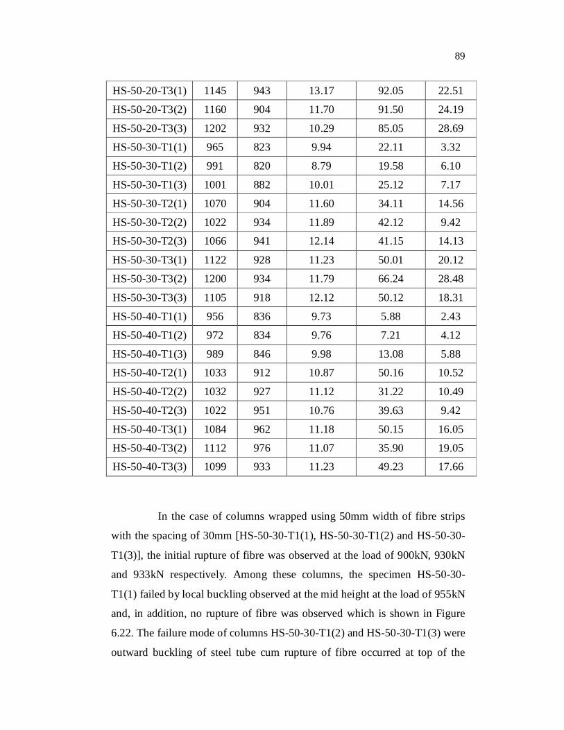
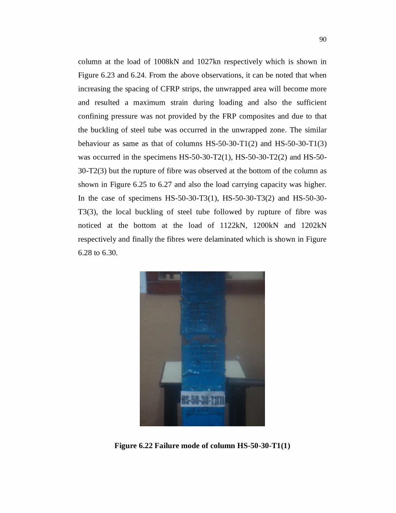
In the case of columns wrapped using 50mm width of fibre strips
with the spacing of 30mm [HS-50-30-T1(1), HS-50-30-T1(2) and HS-50-30-
T1(3)], the initial rupture of fibre was observed at the load of 900kN, 930kN
and 933kN respectively. Among these columns, the specimen HS-50-30-
T1(1) failed by local buckling observed at the mid height at the load of 955kN
and, in addition, no rupture of fibre was observed which is shown in Figure
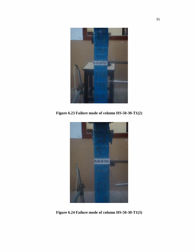
6.22. The failure mode of columns HS-50-30-T1(2) and HS-50-30-T1(3) were
outward buckling of steel tube cum rupture of fibre occurred at top of the
90
column at the load of 1008kN and 1027kn respectively which is shown in
Figure 6.23 and 6.24. From the above observations, it can be noted that when
increasing the spacing of CFRP strips, the unwrapped area will become more
and resulted a maximum strain during loading and also the sufficient
confining pressure was not provided by the FRP composites and due to that
the buckling of steel tube was occurred in the unwrapped zone. The similar
behaviour as same as that of columns HS-50-30-T1(2) and HS-50-30-T1(3)
was occurred in the specimens HS-50-30-T2(1), HS-50-30-T2(2) and HS-50-
30-T2(3) but the rupture of fibre was observed at the bottom of the column as
shown in Figure 6.25 to 6.27 and also the load carrying capacity was higher.
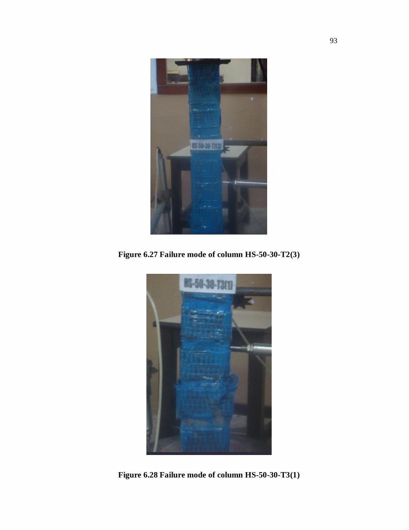
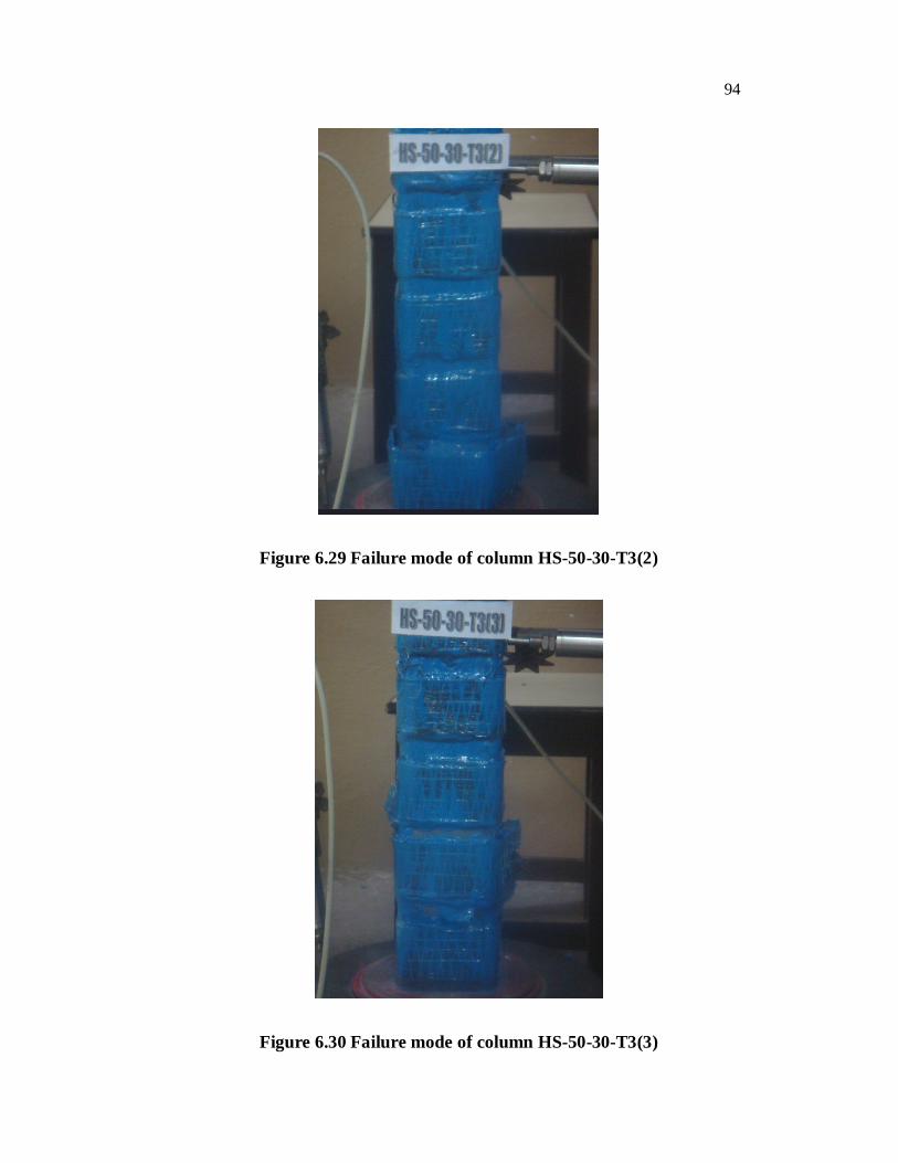
In the case of specimens HS-50-30-T3(1), HS-50-30-T3(2) and HS-50-30-
T3(3), the local buckling of steel tube followed by rupture of fibre was
noticed at the bottom at the load of 1122kN, 1200kN and 1202kN
respectively and finally the fibres were delaminated which is shown in Figure
6.28 to 6.30.
Figure 6.22 Failure mode of column HS-50-30-T1(1)
91
Figure 6.23 Failure mode of column HS-50-30-T1(2)
Figure 6.24 Failure mode of column HS-50-30-T1(3)

92
Figure 6.25 Failure mode of column HS-50-30-T2(1)
Figure 6.26 Failure mode of column HS-50-30-T2(2)
93
Figure 6.27 Failure mode of column HS-50-30-T2(3)
Figure 6.28 Failure mode of column HS-50-30-T3(1)
94
Figure 6.29 Failure mode of column HS-50-30-T3(2)
Figure 6.30 Failure mode of column HS-50-30-T3(3)
95
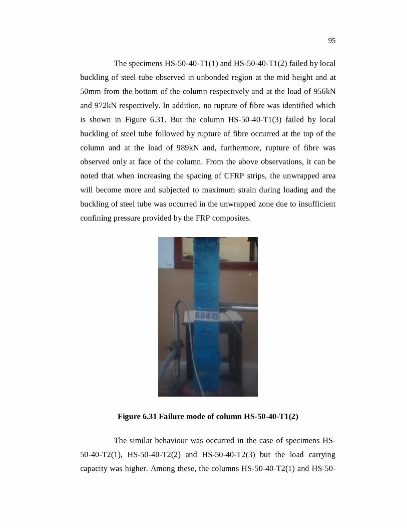
The specimens HS-50-40-T1(1) and HS-50-40-T1(2) failed by local
buckling of steel tube observed in unbonded region at the mid height and at
50mm from the bottom of the column respectively and at the load of 956kN
and 972kN respectively. In addition, no rupture of fibre was identified which
is shown in Figure 6.31. But the column HS-50-40-T1(3) failed by local
buckling of steel tube followed by rupture of fibre occurred at the top of the
column and at the load of 989kN and, furthermore, rupture of fibre was
observed only at face of the column. From the above observations, it can be
noted that when increasing the spacing of CFRP strips, the unwrapped area
will become more and subjected to maximum strain during loading and the
buckling of steel tube was occurred in the unwrapped zone due to insufficient
confining pressure provided by the FRP composites.
Figure 6.31 Failure mode of column HS-50-40-T1(2)
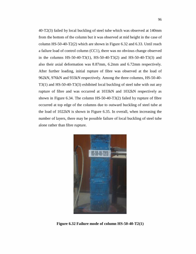
The similar behaviour was occurred in the case of specimens HS-
50-40-T2(1), HS-50-40-T2(2) and HS-50-40-T2(3) but the load carrying
capacity was higher. Among these, the columns HS-50-40-T2(1) and HS-50-
96
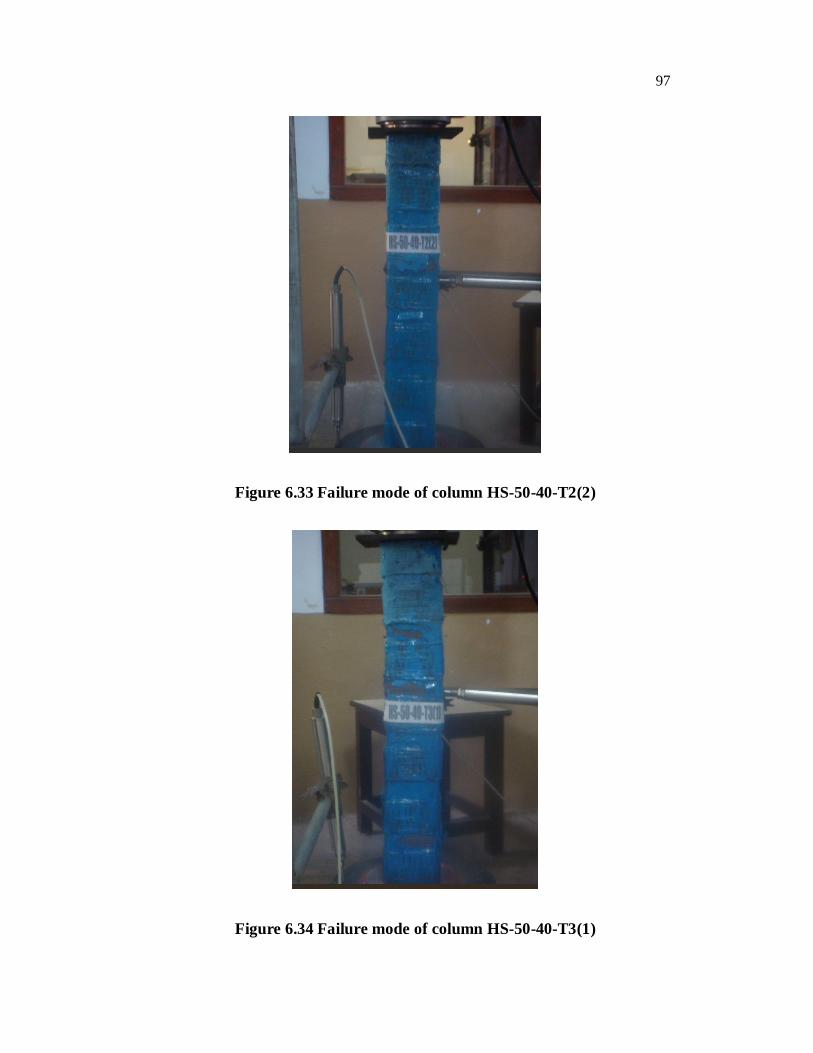
40-T2(3) failed by local buckling of steel tube which was observed at 140mm
from the bottom of the column but it was observed at mid height in the case of
column HS-50-40-T2(2) which are shown in Figure 6.32 and 6.33. Until reach
a failure load of control column (CC1), there was no obvious change observed
in the columns HS-50-40-T3(1), HS-50-40-T3(2) and HS-50-40-T3(3) and
also their axial deformation was 8.87mm, 6.2mm and 6.72mm respectively.
After further loading, initial rupture of fibre was observed at the load of
962kN, 976kN and 933kN respectively. Among the three columns, HS-50-40-
T3(1) and HS-50-40-T3(3) exhibited local buckling of steel tube with out any
rupture of fibre and was occurred at 1033kN and 1032kN respectively as
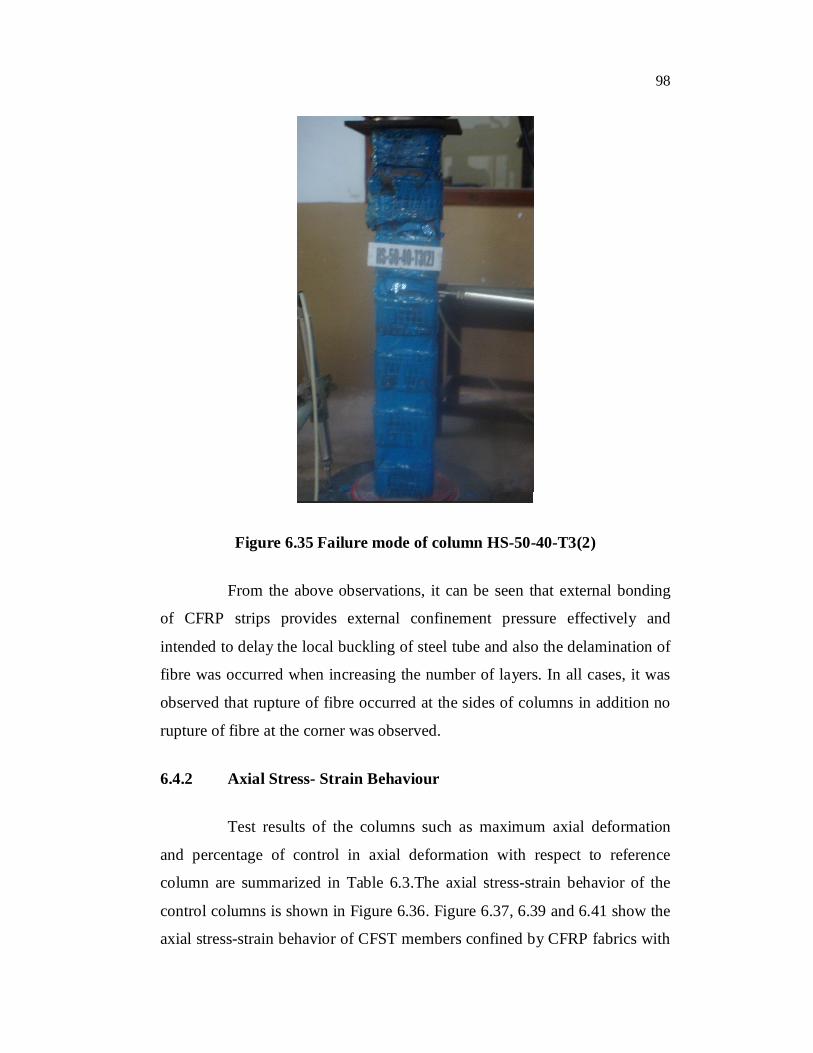
shown in Figure 6.34. The column HS-50-40-T3(2) failed by rupture of fibre
occurred at top edge of the columns due to outward buckling of steel tube at
the load of 1022kN is shown in Figure 6.35. In overall, when increasing the
number of layers, there may be possible failure of local buckling of steel tube
alone rather than fibre rupture.
Figure 6.32 Failure mode of column HS-50-40-T2(1)
97
Figure 6.33 Failure mode of column HS-50-40-T2(2)
Figure 6.34 Failure mode of column HS-50-40-T3(1)
98
Figure 6.35 Failure mode of column HS-50-40-T3(2)
From the above observations, it can be seen that external bonding
of CFRP strips provides external confinement pressure effectively and
intended to delay the local buckling of steel tube and also the delamination of
fibre was occurred when increasing the number of layers. In all cases, it was
observed that rupture of fibre occurred at the sides of columns in addition no
rupture of fibre at the corner was observed.
6.4.2 Axial Stress- Strain Behaviour
Test results of the columns such as maximum axial deformation
and percentage of control in axial deformation with respect to reference
column are summarized in Table 6.3.The axial stress-strain behavior of the
control columns is shown in Figure 6.36. Figure 6.37, 6.39 and 6.41 show the
axial stress-strain behavior of CFST members confined by CFRP fabrics with
99
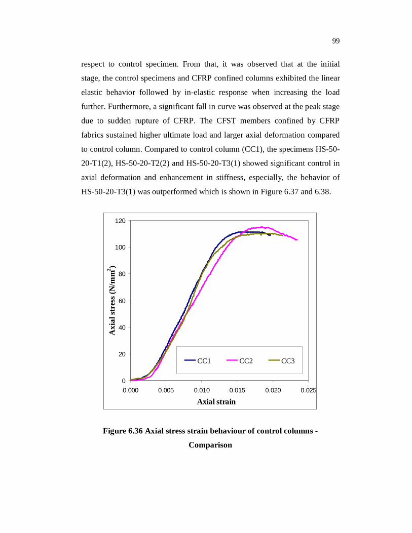
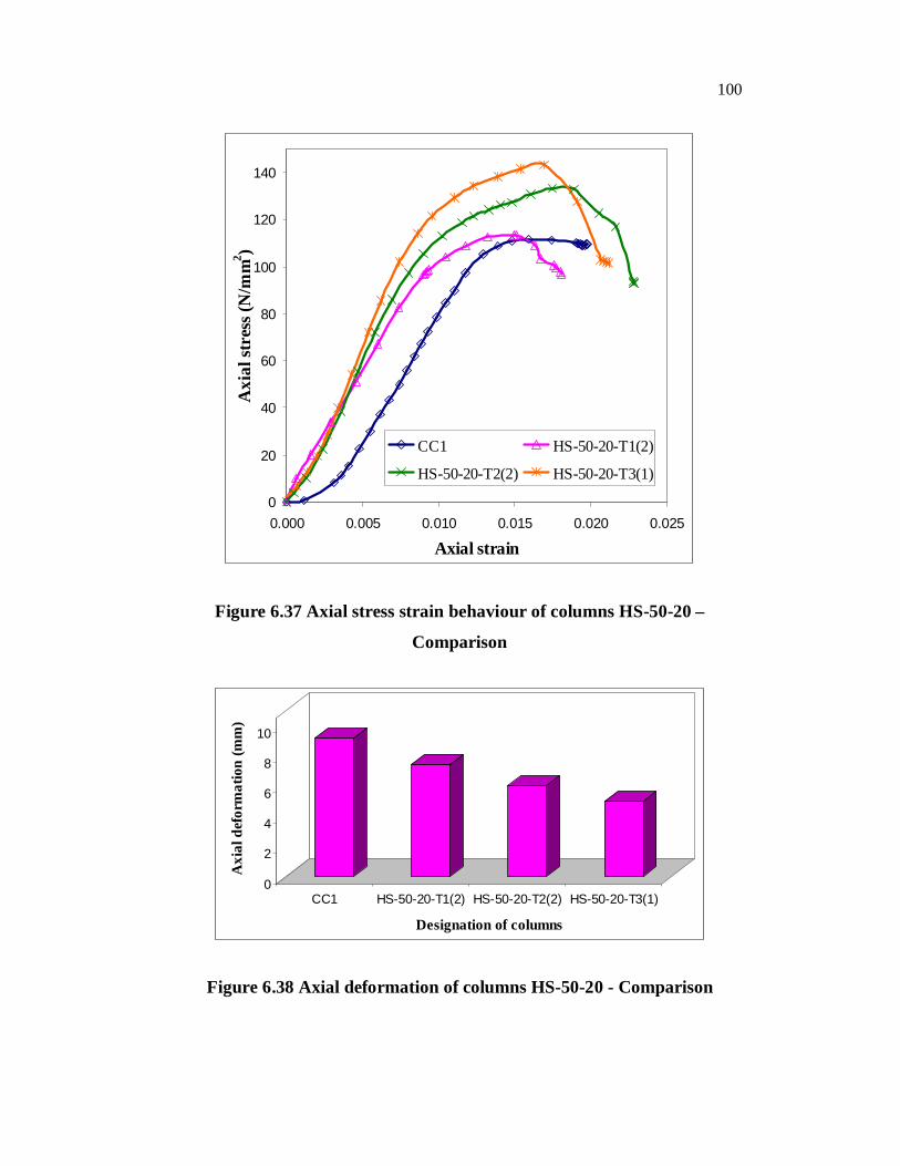
respect to control specimen. From that, it was observed that at the initial
stage, the control specimens and CFRP confined columns exhibited the linear
elastic behavior followed by in-elastic response when increasing the load
further. Furthermore, a significant fall in curve was observed at the peak stage
due to sudden rupture of CFRP. The CFST members confined by CFRP
fabrics sustained higher ultimate load and larger axial deformation compared
to control column. Compared to control column (CC1), the specimens HS-50-
20-T1(2), HS-50-20-T2(2) and HS-50-20-T3(1) showed significant control in
axial deformation and enhancement in stiffness, especially, the behavior of
HS-50-20-T3(1) was outperformed which is shown in Figure 6.37 and 6.38.
0
20
40
60
80
100
120
0.000 0.005 0.010 0.015 0.020 0.025
Axial strain
Axi
al st
ress
(N/m
m2 )
CC1 CC2 CC3
Figure 6.36 Axial stress strain behaviour of control columns -
Comparison
100
0
20
40
60
80
100
120
140
0.000 0.005 0.010 0.015 0.020 0.025
Axial strain
Axi
al st
ress
(N/m
m2 )
CC1 HS-50-20-T1(2)
HS-50-20-T2(2) HS-50-20-T3(1)
Figure 6.37 Axial stress strain behaviour of columns HS-50-20 –
Comparison
0
2
4
6
8
10
Axi
al d
efor
mat
ion
(mm
)
CC1 HS-50-20-T1(2) HS-50-20-T2(2) HS-50-20-T3(1)
Designation of columns
Figure 6.38 Axial deformation of columns HS-50-20 - Comparison
101
At the failure load of CC1, the mid span deflection of specimens
HS-50-20-T1(2), HS-50-20-T2(2) and HS-50-20-T3(1) observed was
7.43mm, 5.92mm and 4.95mm respectively and their enhancement in axial
deformation control compared to control column was 23.28%, 52.66% and
85.05% respectively. The axial deformation control of column HS-50-20-
T1(2) was very small which is due to insufficient amount of confining
pressure generated by FRP fabrics. The axial stress strain behavior of column
HS-50-20-T3(1) followed the same path of HS-50-20-T2(2) until reach the
load of 670kN but the enhancement in axial deformation control of HS-50-20-
T3(1) was much better than that of HS-50-20-T2(2) which is shown in Figure
6.36. From the Figure 6.38, it can be seen that the columns confined with
three layers of CFRP tend to have more ability to control axial deformation
compared to those columns confined by one and two layers of CFRP.
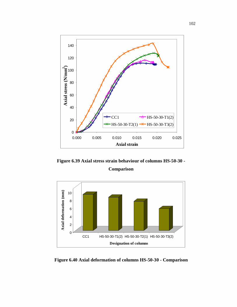
According to the Figure 6.40, the columns HS-50-30-T1(2), HS-50-
30-T2(1) and HS-50-30-T3(2) enhanced their axial deformation control by
19.58%, 34.11% and 66.24% respectively compared to the control column
(CC1) and their axial deformation at failure load of control column (CC1) was
7.66mm, 6.83mm and 5.51mm respectively. The axial stress strain behavior
of column HS-50-30-T1(2) followed the same path of HS-50-30-T2(1) until
reach the load of 810kN, and thereafter, relaxation in axial deformation
control was observed and, in addition, the column HS-50-30-T2(2) sustained
higher ultimate load and larger axial deformation control which is shown in
Figure 6.39. The mid-span deflection of column HS-50-30-T3(2) at the
respective failure load of columns HS-50-30-T1(2) and HS-50-30-T2(1) was
5.85mm and 7.23mm and the percentage of enhancement in axial deformation
control was 51.11% and 43.70% respectively as shown in Figure 6.40.
102
0
20
40
60
80
100
120
140
0.000 0.005 0.010 0.015 0.020 0.025
Axial strain
Axi
al st
ress
(N/m
m2 )
CC1 HS-50-30-T1(2)
HS-50-30-T2(1) HS-50-30-T3(2)
Figure 6.39 Axial stress strain behaviour of columns HS-50-30 -
Comparison
0
2
4
6
8
10
Axi
al d
efor
mat
ion
(mm
)
CC1 HS-50-30-T1(2) HS-50-30-T2(1) HS-50-30-T3(2)
Designation of columns
Figure 6.40 Axial deformation of columns HS-50-30 - Comparison
103
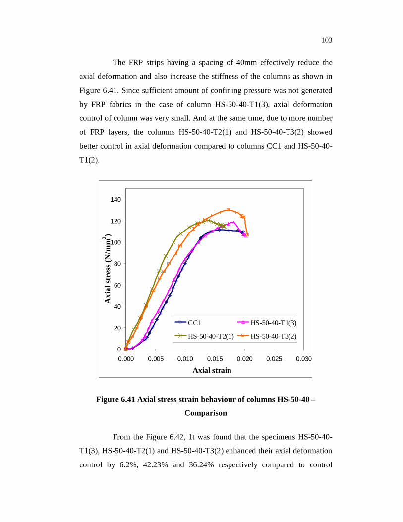
The FRP strips having a spacing of 40mm effectively reduce the
axial deformation and also increase the stiffness of the columns as shown in
Figure 6.41. Since sufficient amount of confining pressure was not generated
by FRP fabrics in the case of column HS-50-40-T1(3), axial deformation
control of column was very small. And at the same time, due to more number
of FRP layers, the columns HS-50-40-T2(1) and HS-50-40-T3(2) showed
better control in axial deformation compared to columns CC1 and HS-50-40-
T1(2).
0
20
40
60
80
100
120
140
0.000 0.005 0.010 0.015 0.020 0.025 0.030
Axial strain
Axi
al st
ress
(N/m
m2 )
CC1 HS-50-40-T1(3)
HS-50-40-T2(1) HS-50-40-T3(2)
Figure 6.41 Axial stress strain behaviour of columns HS-50-40 –
Comparison
From the Figure 6.42, 1t was found that the specimens HS-50-40-
T1(3), HS-50-40-T2(1) and HS-50-40-T3(2) enhanced their axial deformation
control by 6.2%, 42.23% and 36.24% respectively compared to control
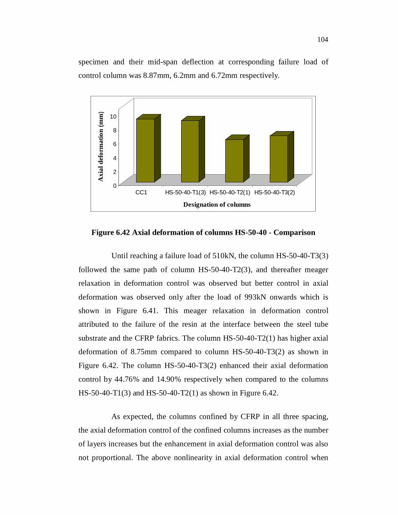
104
specimen and their mid-span deflection at corresponding failure load of
control column was 8.87mm, 6.2mm and 6.72mm respectively.
0
2
4
6
8
10
Axi
al d
efor
mat
ion
(mm
)
CC1 HS-50-40-T1(3) HS-50-40-T2(1) HS-50-40-T3(2)
Designation of columns
Figure 6.42 Axial deformation of columns HS-50-40 - Comparison
Until reaching a failure load of 510kN, the column HS-50-40-T3(3)
followed the same path of column HS-50-40-T2(3), and thereafter meager
relaxation in deformation control was observed but better control in axial
deformation was observed only after the load of 993kN onwards which is
shown in Figure 6.41. This meager relaxation in deformation control
attributed to the failure of the resin at the interface between the steel tube
substrate and the CFRP fabrics. The column HS-50-40-T2(1) has higher axial
deformation of 8.75mm compared to column HS-50-40-T3(2) as shown in
Figure 6.42. The column HS-50-40-T3(2) enhanced their axial deformation
control by 44.76% and 14.90% respectively when compared to the columns
HS-50-40-T1(3) and HS-50-40-T2(1) as shown in Figure 6.42.
As expected, the columns confined by CFRP in all three spacing,
the axial deformation control of the confined columns increases as the number
of layers increases but the enhancement in axial deformation control was also
not proportional. The above nonlinearity in axial deformation control when
105
increasing the number of layers of fibre may be attributed to crushing of resin
lying in between the fibres. When the resin started to crush, a sudden drop in
substantial load transfer was occurred. As a result, non linearity in axial
deformation control was observed. Furthermore, by increasing the number of
layers of fibre fabrics, the number of resin layers also increased so that more
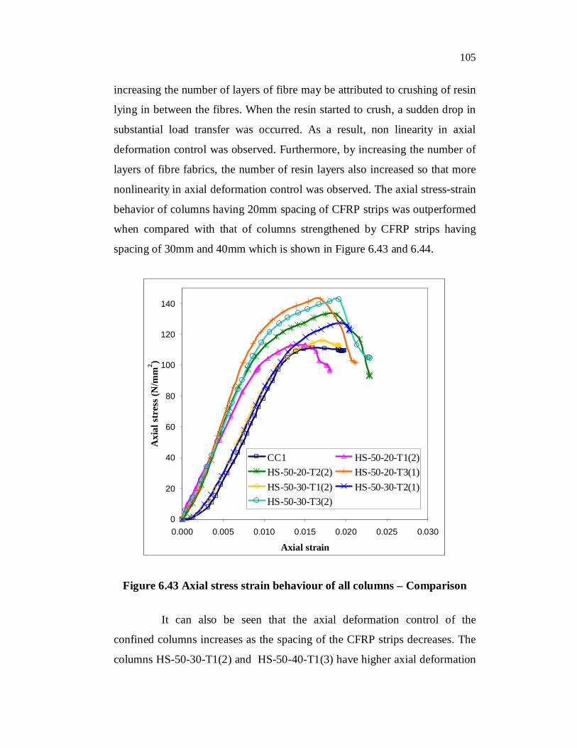
nonlinearity in axial deformation control was observed. The axial stress-strain
behavior of columns having 20mm spacing of CFRP strips was outperformed
when compared with that of columns strengthened by CFRP strips having
spacing of 30mm and 40mm which is shown in Figure 6.43 and 6.44.
0
20
40
60
80
100
120
140
0.000 0.005 0.010 0.015 0.020 0.025 0.030
Axial strain
Axi
al st
ress
(N/m
m2 )
CC1 HS-50-20-T1(2)HS-50-20-T2(2) HS-50-20-T3(1)HS-50-30-T1(2) HS-50-30-T2(1)HS-50-30-T3(2)
Figure 6.43 Axial stress strain behaviour of all columns – Comparison
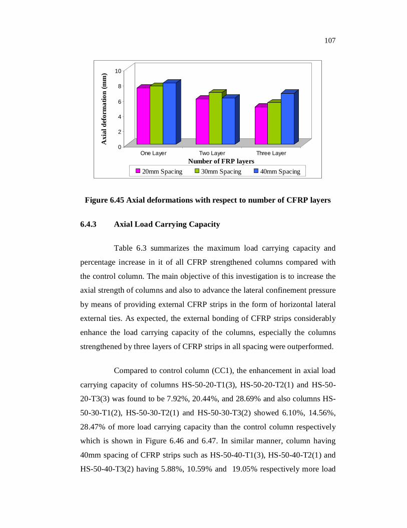
It can also be seen that the axial deformation control of the
confined columns increases as the spacing of the CFRP strips decreases. The
columns HS-50-30-T1(2) and HS-50-40-T1(3) have higher axial deformation
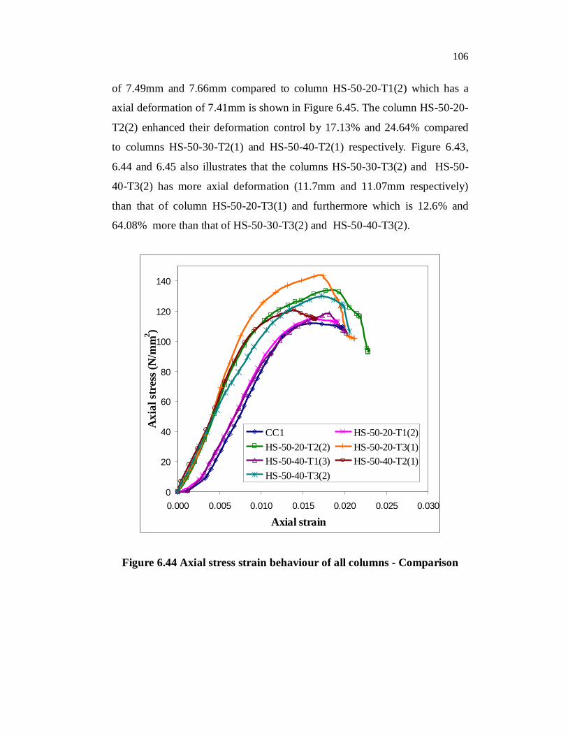
106
of 7.49mm and 7.66mm compared to column HS-50-20-T1(2) which has a
axial deformation of 7.41mm is shown in Figure 6.45. The column HS-50-20-
T2(2) enhanced their deformation control by 17.13% and 24.64% compared
to columns HS-50-30-T2(1) and HS-50-40-T2(1) respectively. Figure 6.43,
6.44 and 6.45 also illustrates that the columns HS-50-30-T3(2) and HS-50-
40-T3(2) has more axial deformation (11.7mm and 11.07mm respectively)
than that of column HS-50-20-T3(1) and furthermore which is 12.6% and
64.08% more than that of HS-50-30-T3(2) and HS-50-40-T3(2).
0
20
40
60
80
100
120
140
0.000 0.005 0.010 0.015 0.020 0.025 0.030
Axial strain
Axi
al st
ress
(N/m
m2 )
CC1 HS-50-20-T1(2)HS-50-20-T2(2) HS-50-20-T3(1)HS-50-40-T1(3) HS-50-40-T2(1)HS-50-40-T3(2)
Figure 6.44 Axial stress strain behaviour of all columns - Comparison
107
0
2
4
6
8
10
Axi
al d
efor
mat
ion
(mm
)
One Layer Two Layer Three LayerNumber of FRP layers
20mm Spacing 30mm Spacing 40mm Spacing
Figure 6.45 Axial deformations with respect to number of CFRP layers
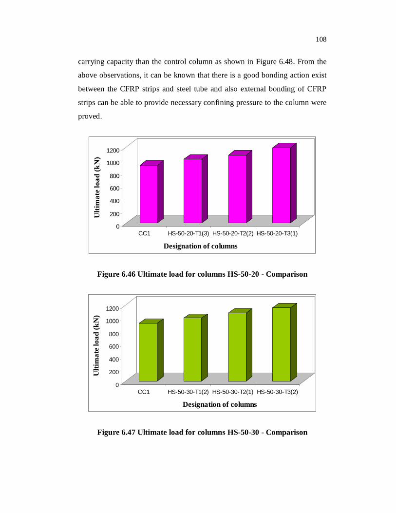
6.4.3 Axial Load Carrying Capacity
Table 6.3 summarizes the maximum load carrying capacity and
percentage increase in it of all CFRP strengthened columns compared with
the control column. The main objective of this investigation is to increase the
axial strength of columns and also to advance the lateral confinement pressure
by means of providing external CFRP strips in the form of horizontal lateral
external ties. As expected, the external bonding of CFRP strips considerably
enhance the load carrying capacity of the columns, especially the columns
strengthened by three layers of CFRP strips in all spacing were outperformed.
Compared to control column (CC1), the enhancement in axial load
carrying capacity of columns HS-50-20-T1(3), HS-50-20-T2(1) and HS-50-
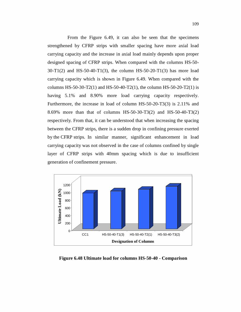
20-T3(3) was found to be 7.92%, 20.44%, and 28.69% and also columns HS-
50-30-T1(2), HS-50-30-T2(1) and HS-50-30-T3(2) showed 6.10%, 14.56%,
28.47% of more load carrying capacity than the control column respectively
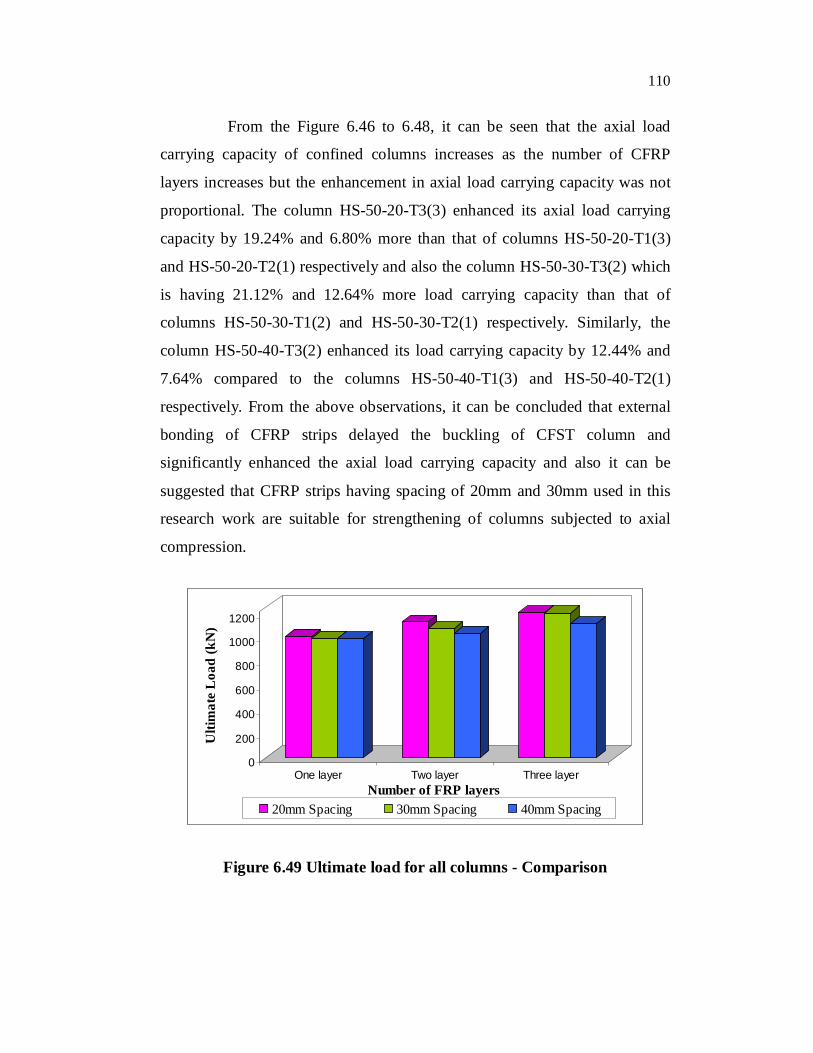
which is shown in Figure 6.46 and 6.47. In similar manner, column having
40mm spacing of CFRP strips such as HS-50-40-T1(3), HS-50-40-T2(1) and
HS-50-40-T3(2) having 5.88%, 10.59% and 19.05% respectively more load
108
carrying capacity than the control column as shown in Figure 6.48. From the
above observations, it can be known that there is a good bonding action exist
between the CFRP strips and steel tube and also external bonding of CFRP
strips can be able to provide necessary confining pressure to the column were
proved.
0
200
400
600
800
1000
1200
Ulti
mat
e loa
d (k
N)
CC1 HS-50-20-T1(3) HS-50-20-T2(2) HS-50-20-T3(1)
Designation of columns
Figure 6.46 Ultimate load for columns HS-50-20 - Comparison
0
200
400
600
800
1000
1200
Ulti
mat
e loa
d (k
N)
CC1 HS-50-30-T1(2) HS-50-30-T2(1) HS-50-30-T3(2)
Designation of columns
Figure 6.47 Ultimate load for columns HS-50-30 - Comparison
109
From the Figure 6.49, it can also be seen that the specimens
strengthened by CFRP strips with smaller spacing have more axial load
carrying capacity and the increase in axial load mainly depends upon proper
designed spacing of CFRP strips. When compared with the columns HS-50-
30-T1(2) and HS-50-40-T1(3), the column HS-50-20-T1(3) has more load
carrying capacity which is shown in Figure 6.49. When compared with the
columns HS-50-30-T2(1) and HS-50-40-T2(1), the column HS-50-20-T2(1) is
having 5.1% and 8.90% more load carrying capacity respectively.
Furthermore, the increase in load of column HS-50-20-T3(3) is 2.11% and
8.69% more than that of columns HS-50-30-T3(2) and HS-50-40-T3(2)
respectively. From that, it can be understood that when increasing the spacing
between the CFRP strips, there is a sudden drop in confining pressure exerted
by the CFRP strips. In similar manner, significant enhancement in load
carrying capacity was not observed in the case of columns confined by single
layer of CFRP strips with 40mm spacing which is due to insufficient
generation of confinement pressure.
0
200
400
600
800
1000
1200
Ulti
mat
e L
oad
(kN
)
CC1 HS-50-40-T1(3) HS-50-40-T2(1) HS-50-40-T3(2)
Designation of Columns
Figure 6.48 Ultimate load for columns HS-50-40 - Comparison
110
From the Figure 6.46 to 6.48, it can be seen that the axial load
carrying capacity of confined columns increases as the number of CFRP
layers increases but the enhancement in axial load carrying capacity was not
proportional. The column HS-50-20-T3(3) enhanced its axial load carrying
capacity by 19.24% and 6.80% more than that of columns HS-50-20-T1(3)
and HS-50-20-T2(1) respectively and also the column HS-50-30-T3(2) which
is having 21.12% and 12.64% more load carrying capacity than that of
columns HS-50-30-T1(2) and HS-50-30-T2(1) respectively. Similarly, the
column HS-50-40-T3(2) enhanced its load carrying capacity by 12.44% and
7.64% compared to the columns HS-50-40-T1(3) and HS-50-40-T2(1)
respectively. From the above observations, it can be concluded that external
bonding of CFRP strips delayed the buckling of CFST column and
significantly enhanced the axial load carrying capacity and also it can be
suggested that CFRP strips having spacing of 20mm and 30mm used in this
research work are suitable for strengthening of columns subjected to axial
compression.
0
200
400
600
800
1000
1200
Ulti
mat
e L
oad
(kN
)
One layer Two layer Three layerNumber of FRP layers
20mm Spacing 30mm Spacing 40mm Spacing
Figure 6.49 Ultimate load for all columns - Comparison
111
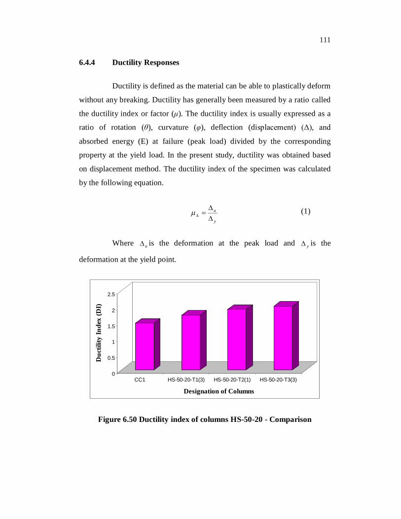
6.4.4 Ductility Responses
Ductility is defined as the material can be able to plastically deform
without any breaking. Ductility has generally been measured by a ratio called
the ductility index or factor (μ). The ductility index is usually expressed as a
ratio of rotation (θ), curvature (φ), deflection (displacement) (Δ), and
absorbed energy (E) at failure (peak load) divided by the corresponding
property at the yield load. In the present study, ductility was obtained based
on displacement method. The ductility index of the specimen was calculated
by the following equation.
y
u
(1)
Where u is the deformation at the peak load and y is the
deformation at the yield point.
0
0.5
1
1.5
2
2.5
Duc
tility
Inde
x (D
I)
CC1 HS-50-20-T1(3) HS-50-20-T2(1) HS-50-20-T3(3)
Designation of Columns
Figure 6.50 Ductility index of columns HS-50-20 - Comparison
112
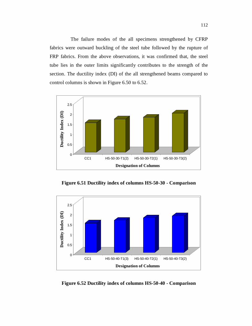
The failure modes of the all specimens strengthened by CFRP
fabrics were outward buckling of the steel tube followed by the rupture of
FRP fabrics. From the above observations, it was confirmed that, the steel
tube lies in the outer limits significantly contributes to the strength of the
section. The ductility index (DI) of the all strengthened beams compared to
control columns is shown in Figure 6.50 to 6.52.
0
0.5
1
1.5
2
2.5
Duc
tility
Inde
x (D
I)
CC1 HS-50-30-T1(2) HS-50-30-T2(1) HS-50-30-T3(2)
Designation of Columns
Figure 6.51 Ductility index of columns HS-50-30 - Comparison
0
0.5
1
1.5
2
2.5
Duc
tility
Inde
x (D
I)
CC1 HS-50-40-T1(3) HS-50-40-T2(1) HS-50-40-T3(2)
Designation of Columns
Figure 6.52 Ductility index of columns HS-50-40 - Comparison
113
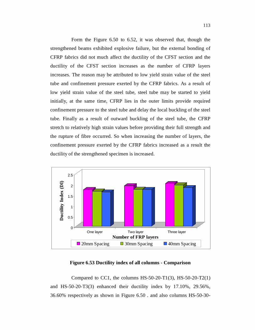
Form the Figure 6.50 to 6.52, it was observed that, though the
strengthened beams exhibited explosive failure, but the external bonding of
CFRP fabrics did not much affect the ductility of the CFST section and the
ductility of the CFST section increases as the number of CFRP layers
increases. The reason may be attributed to low yield strain value of the steel
tube and confinement pressure exerted by the CFRP fabrics. As a result of
low yield strain value of the steel tube, steel tube may be started to yield
initially, at the same time, CFRP lies in the outer limits provide required
confinement pressure to the steel tube and delay the local buckling of the steel
tube. Finally as a result of outward buckling of the steel tube, the CFRP
stretch to relatively high strain values before providing their full strength and
the rupture of fibre occurred. So when increasing the number of layers, the
confinement pressure exerted by the CFRP fabrics increased as a result the
ductility of the strengthened specimen is increased.
0
0.5
1
1.5
2
2.5
Duc
tility
Inde
x (D
I)
One layer Two layer Three layerNumber of FRP layers
20mm Spacing 30mm Spacing 40mm Spacing
Figure 6.53 Ductility index of all columns - Comparison
Compared to CC1, the columns HS-50-20-T1(3), HS-50-20-T2(1)
and HS-50-20-T3(3) enhanced their ductility index by 17.10%, 29.56%,
36.60% respectively as shown in Figure 6.50 . and also columns HS-50-30-
114
T1(2), HS-50-30-T2(1) and HS-50-30-T3(2) showed 12.33%, 18.10%,
32.32% respectively of more ductility than the control column which is shown
in Figure 6.51. In similar manner, the columns having 40mm spacing of
CFRP strips such as HS-50-40-T1(3), HS-50-40-T2(1) and HS-50-40-T3(2)
having 9.25%, 17.39% and 24.10% respectively increase in ductility than the
control column as shown in Figure 6.52. From the Figure 6.53 it was also
observed that, the effect of increase in spacing between the CFRP strips on
ductility enhancement was not obvious.
6.5 ANALYTICAL STUDY
6.5.1 Prediction of the Axial Strength of FRP Confined CFST
Column
6.5.1.1 Existing confinement models
Jerome F. Hajjar and Brett C. Gourley (1995) proposed the
following equation for predicting the load carrying capacity (Po) of the CFST
column under axial compression.
cconcreteysteelo fAfAP (2)
Where yf = yield stress of steel tube, cf = cylinder compressive
strength of concrete and steelA and concreteA are cross sectional area of steel tube
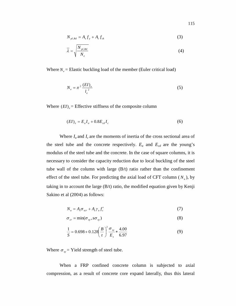
and filled concrete. The axial load carrying capacity ( RdplN , ) of the CFT
columns according to EC4 can be determined by summing up the strengths of
the steel tube and the concrete core as in Equation 3. The application of EC4
is restricted to composite columns with concrete cylinder strength and steel
yield stress not greater than 50 and 355 MPa, respectively.
115
ckcysRdpl fAfAN , (3)
e
Rdpl
NN , (4)
Where eN = Elastic buckling load of the member (Euler critical load)
22 )(
e
ee l
EIN (5)
Where eEI)( = Effective stiffness of the composite column
ccdaae IEIEEI 8.0)( (6)
Where Ia and Ic are the moments of inertia of the cross sectional area of
the steel tube and the concrete respectively. Ea and Ecd are the young’s
modulus of the steel tube and the concrete. In the case of square columns, it is
necessary to consider the capacity reduction due to local buckling of the steel
tube wall of the column with large (B/t) ratio rather than the confinement
effect of the steel tube. For predicting the axial load of CFT column ( uN ), by
taking in to account the large (B/t) ratio, the modified equation given by Kenji
Sakino et al (2004) as follows:
cucscrsu fAAN (7)
),min( sysycr s (8)
97.600.4128.0698.01 2
s
sy
EtB
S
(9)
Where sy = Yield strength of steel tube.
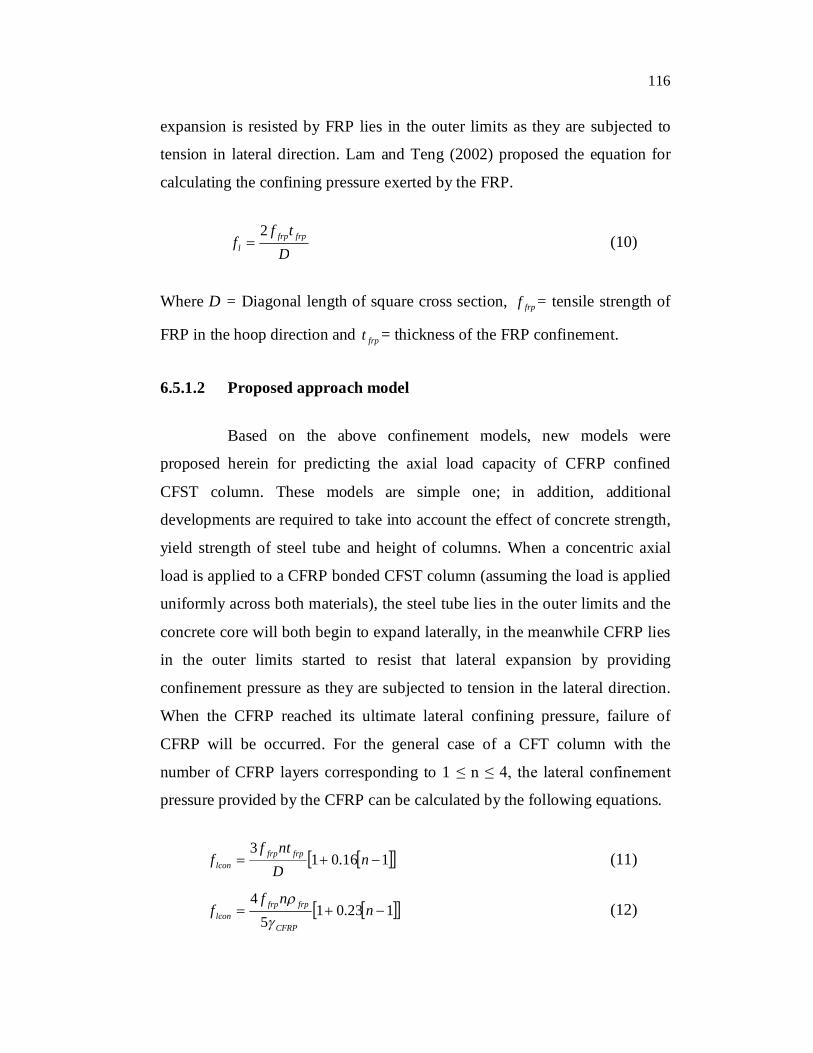
When a FRP confined concrete column is subjected to axial
compression, as a result of concrete core expand laterally, thus this lateral
116
expansion is resisted by FRP lies in the outer limits as they are subjected to
tension in lateral direction. Lam and Teng (2002) proposed the equation for
calculating the confining pressure exerted by the FRP.
D
tff frpfrp
l
2 (10)
Where D = Diagonal length of square cross section, frpf = tensile strength of
FRP in the hoop direction and frpt = thickness of the FRP confinement.
6.5.1.2 Proposed approach model
Based on the above confinement models, new models were
proposed herein for predicting the axial load capacity of CFRP confined
CFST column. These models are simple one; in addition, additional
developments are required to take into account the effect of concrete strength,
yield strength of steel tube and height of columns. When a concentric axial
load is applied to a CFRP bonded CFST column (assuming the load is applied
uniformly across both materials), the steel tube lies in the outer limits and the
concrete core will both begin to expand laterally, in the meanwhile CFRP lies
in the outer limits started to resist that lateral expansion by providing
confinement pressure as they are subjected to tension in the lateral direction.
When the CFRP reached its ultimate lateral confining pressure, failure of
CFRP will be occurred. For the general case of a CFT column with the
number of CFRP layers corresponding to 1 ≤ n ≤ 4, the lateral confinement
pressure provided by the CFRP can be calculated by the following equations.
116.013
nDntf
f frpfrplcon (11)
123.015
4 n
nff
CFRP
frpfrplcon
(12)
117
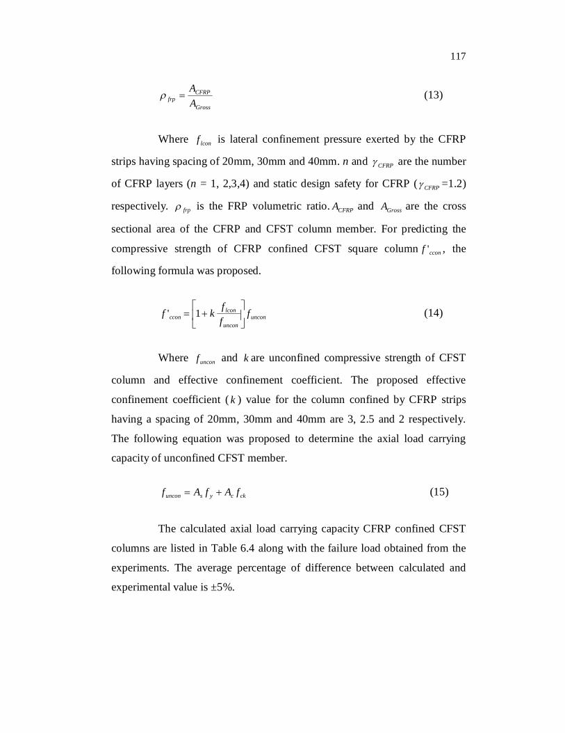
Gross
CFRPfrp A
A (13)
Where lconf is lateral confinement pressure exerted by the CFRP
strips having spacing of 20mm, 30mm and 40mm. n and CFRP are the number
of CFRP layers (n = 1, 2,3,4) and static design safety for CFRP ( CFRP =1.2)
respectively. frp is the FRP volumetric ratio. CFRPA and GrossA are the cross
sectional area of the CFRP and CFST column member. For predicting the
compressive strength of CFRP confined CFST square column cconf ' , the
following formula was proposed.
unconuncon
lconccon f
ffkf
1' (14)
Where unconf and k are unconfined compressive strength of CFST
column and effective confinement coefficient. The proposed effective
confinement coefficient ( k ) value for the column confined by CFRP strips
having a spacing of 20mm, 30mm and 40mm are 3, 2.5 and 2 respectively.
The following equation was proposed to determine the axial load carrying
capacity of unconfined CFST member.
ckcysuncon fAfAf (15)
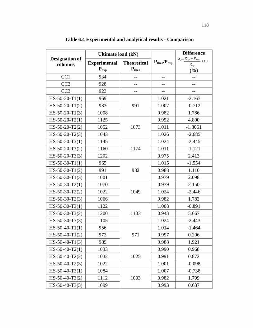
The calculated axial load carrying capacity CFRP confined CFST
columns are listed in Table 6.4 along with the failure load obtained from the
experiments. The average percentage of difference between calculated and
experimental value is ±5%.
118
Table 6.4 Experimental and analytical results - Comparison
Designation of columns
Ultimate load (kN) Ptheo/Pexp
Difference ∆= 100
exp
exp XP
PP theo
(%) Experimental
Pexp Theoretical
Ptheo CC1 934 -- -- -- CC2 928 -- -- -- CC3 923 -- -- --
HS-50-20-T1(1) 969 991
1.021 -2.167 HS-50-20-T1(2) 983 1.007 -0.712 HS-50-20-T1(3) 1008 0.982 1.786 HS-50-20-T2(1) 1125
1073 0.952 4.800
HS-50-20-T2(2) 1052 1.011 -1.8061 HS-50-20-T2(3) 1043 1.026 -2.685 HS-50-20-T3(1) 1145
1174 1.024 -2.445
HS-50-20-T3(2) 1160 1.011 -1.121 HS-50-20-T3(3) 1202 0.975 2.413 HS-50-30-T1(1) 965
982 1.015 -1.554
HS-50-30-T1(2) 991 0.988 1.110 HS-50-30-T1(3) 1001 0.979 2.098 HS-50-30-T2(1) 1070
1049 0.979 2.150
HS-50-30-T2(2) 1022 1.024 -2.446 HS-50-30-T2(3) 1066 0.982 1.782 HS-50-30-T3(1) 1122
1133 1.008 -0.891
HS-50-30-T3(2) 1200 0.943 5.667 HS-50-30-T3(3) 1105 1.024 -2.443 HS-50-40-T1(1) 956
971 1.014 -1.464
HS-50-40-T1(2) 972 0.997 0.206 HS-50-40-T1(3) 989 0.988 1.921 HS-50-40-T2(1) 1033
1025 0.990 0.968
HS-50-40-T2(2) 1032 0.991 0.872 HS-50-40-T2(3) 1022 1.001 -0.098 HS-50-40-T3(1) 1084
1093 1.007 -0.738
HS-50-40-T3(2) 1112 0.982 1.799 HS-50-40-T3(3) 1099 0.993 0.637
119
6.6 CONCLUSION
Horizontal wrapping style of narrow strip of CFRP fabrics was
proposed in this study for improving the confinement pressure of concrete
filled steel tubular members externally. From the experimental data obtained,
the failure modes, axial stress-stain behaviour, ultimate load carrying capacity
and the contribution of FRP fabrics on CFT columns were discussed. And
also analytical model was developed for predicting the axial load capacity of
CFRP confined CFST columns. Based on the compressive tests on specimens
wrapped with CFRP strips with different spacing, the following conclusions
can be made
6.6.1 Columns Strengthened By 30mm Wide CFRP Strips
The columns strengthened by 30mm CFRP strips having a
spacing of 20mm, effectively control the axial deformation
compared to the columns strengthened by same width of CFRP
strips having a spacing of 40mm and 60mm.
The external bonding of CFRP strips considerably enhances the
load-carrying capacity of the columns, especially the columns
strengthened by three layers of CFRP strips was outperformed.
The columns HS-30-20-T3, HS-30-40-T3 and HS-30-60-T3
showed 27.05%, 16.47%, and 9.41% respectively more load-
carrying capacity than the control column.
The external bonding of CFRP strips significantly enhances the
axial load-carrying capacity and delaying of the buckling of
CFST column and also it is suggested that CFRP strips with
smaller spacing is suitable for strengthening of columns
subjected to axial compression.
120
6.6.2 Columns Strengthened By 50mm Wide CFRP Strips
Until reach a load of 850kN on jack, a linear response was
observed in all unwrapped specimens and thereafter non-linear
response was observed. Outward buckling at the top on all four
sides of the steel tube was occurred in the case of control
specimens CC1, CC2 and CC3 at the load of 934kN, 928kN and
923kN respectively.
The columns strengthened by 50mm CFRP strips having a
spacing of 20mm were failed by rupture of fibre which was
occurred at top edge of the columns and thereafter delamination
of fibre due to outward buckling of steel tube was observed on
the sides of the CFST.
When the spacing between the CFRP strips is increased, the
unwrapped area will become more and resulted in maximum
strain during loading and also the sufficient confining pressure
was not provided by the FRP composites and due to that the
buckling of steel tube was occurred in the unwrapped zone.
The columns confined with three layers of CFRP tend to have
more ability to control axial deformation compared to those
columns confined by one and two layers of CFRP. The CFST
members confined by CFRP fabrics sustained higher ultimate
load and larger axial deformation compared to control column.
The enhancement in axial deformation control of columns with
smaller spacing of CFRP strips such as HS-50-20-T1(2), HS-50-
20-T2(2) and HS-50-20-T3(1) compared to control column
121
observed at the failure load of control specimen was 23.28%,
52.66% and 85.05% respectively.
The columns HS-50-30-T1(2), HS-50-30-T2(1) and HS-50-30-
T3(2) enhanced their axial deformation control by 19.58%,
34.11% and 66.24% respectively compared to the control
column (CC1) and their axial deformation at the respective
failure load of control column (CC1) was 7.66mm, 6.83mm and
5.51mm respectively.
When compared to columns HS-50-30-T2(1) and HS-50-30-
T3(2), the axial deformation control of column HS-50-30-T1(2)
was very small which is due to insufficient amount of confining
pressure generated by FRP fabrics.
Until reach the load of 350kN, similar axial stress strain
behavior was observed in the case of columns HS-50-40-T1(3),
HS-50-40-T2(1) and HS-50-40-T3(2) and thereafter due to more
number of FRP layers, the columns HS-50-40-T2(1) and HS-50-
40-T3(2) showed better control in axial deformation compared
to columns CC1 and HS-50-40-T1(3).
The specimens HS-50-40-T1(3), HS-50-40-T2(1) and HS-50-
40-T3(2) enhanced their axial deformation control by 13.08%,
50.16% and 35.90% respectively compared to control specimen
and their mid-span deflection at the respective failure load of
control column was 7.66mm, 5.99mm and 6.74mm respectively.
The axial deformation control of confined columns increases as
the number of layers increases, but the enhancement in axial
deformation control was also not proportional. The above
122
nonlinearity in axial deformation control may be attributed to
crushing of resin lying in between the fibres when increasing
the number of layers of fibre.
The axial stress-strain behavior of columns having 20mm
spacing of CFRP strips was outperformed when compared with
that of columns strengthened by CFRP strips having spacing of
30mm and 40mm.
The column HS-50-20-T2(2) enhanced its deformation control
by 17.13% and 24.64% compared to columns HS-50-30-T2(1)
and HS-50-40-T2(1) respectively.
The columns HS-50-30-T3(2) and HS-50-40-T3(2) have more
axial deformation (11.7mm and 11.07mm respectively) than that
of column HS-50-20-T3(1) and furthermore which is 12.6% and
64.08% more than that HS-50-30-T3(2) and HS-50-40-T3(2).
The external bonding of CFRP strips considerably enhance the
load carrying capacity of the columns, especially the columns
strengthened by three layers of CFRP strips in all spacing were
outperformed.
When compared to control column (CC1), the enhancement in
axial load carrying capacity of columns HS-50-20-T1(3), HS-
50-20-T2(1) and HS-50-20-T3(3) was found to be 7.92%,
20.44%, and 28.69% respectively.
The specimens HS-50-30-T1(2), HS-50-30-T2(1) and HS-50-
30-T3(2) enhanced their axial load carrying capacity by 6.10%,
123
14.56% and 28.47% respectively compared to reference
column.
In similar manner, the columns having 40mm spacing of CFRP
strips such as HS-50-40-T1(3), HS-50-40-T2(1) and HS-50-40-
T3(2) having 5.88%, 10.59% and 19.05% respectively more
load carrying capacity than the control column.
The axial load carrying capacity of the confined columns
increases as the number of CFRP layers increases but the
enhancement in axial load carrying capacity was not
proportional
The specimens strengthened by CFRP strips with smaller
spacing have more axial load carrying capacity and the increase
in axial load mainly depends upon proper spacing of CFRP
strips.
When compared with the columns HS-50-30-T2(1) and HS-50-
40-T2(1), the column HS-50-20-T2(1) is having 5.1% and
8.90% more load carrying capacity respectively.
The increase in load of column HS-50-20-T3(3) is 2.11% and
8.69% more than that of columns HS-50-30-T3(2) and HS-50-
40-T3(2) respectively.
From the above, it can be seen that the CFRP strips with
smaller spacing delayed the buckling of CFST column and
enhanced axial load carrying capacity and also the increase in
axial load mainly depends upon proper spacing of CFRP strips.
124
External bonding of CFRP fabrics did not much affect the
ductility of the CFST section in addition ductility of the CFST
section increases as the number of CFRP layers increases and
also effect of increase in spacing between the CFRP strips on
ductility enhancement was not obvious.
When compared to CC1, the columns HS-50-20-T1(3), HS-50-
20-T2(1) and HS-50-20-T3(3) enhanced their ductility index by
17.10%, 29.56%, 36.60% respectively.
The columns having 40mm spacing of CFRP strips such as HS-
50-40-T1(3), HS-50-40-T2(1) and HS-50-40-T3(2) having
9.25%, 17.39% and 24.10% respectively increase in ductility
than the control column.