CFD Modelling of Sucrose Crystallisation
6
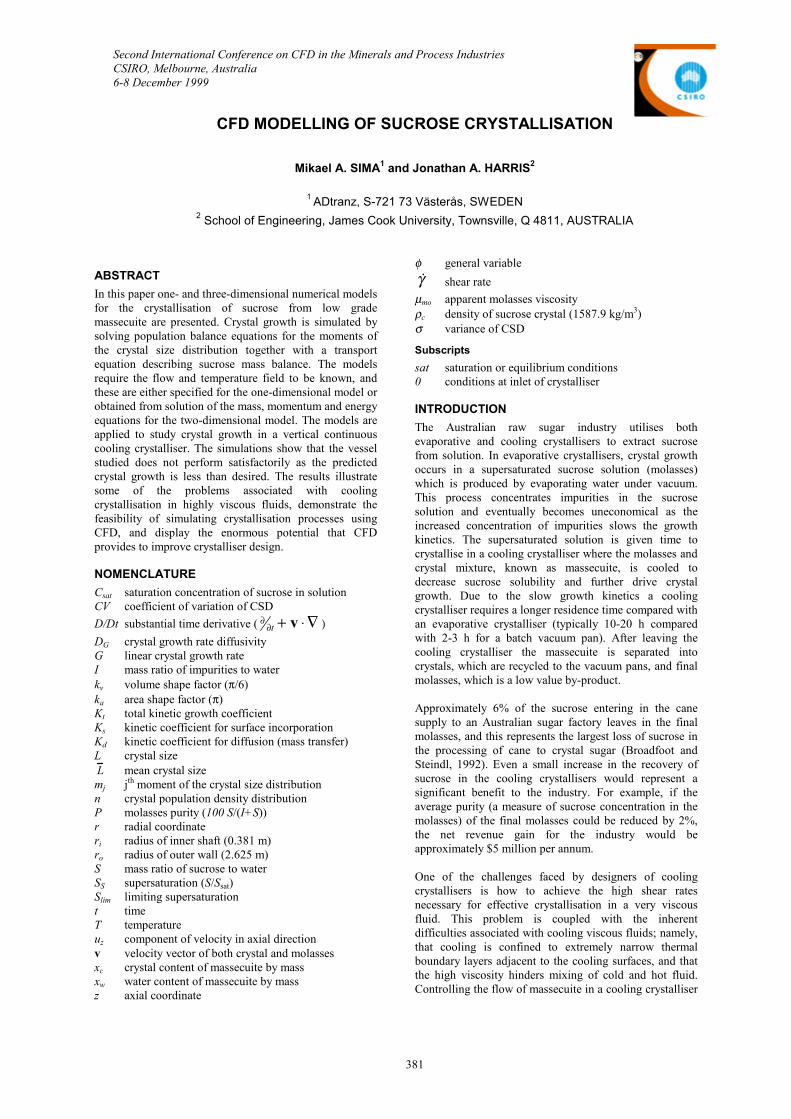
Second International Conference on CFD in the Minerals and Process Industries CSIRO, Melbourne, Australia 6-8 December 1999 381 CFD MODELLING OF SUCROSE CRYSTALLISATION Mikael A. SIMA 1 and Jonathan A. HARRIS 2 1 ADtranz, S-721 73 Västerås, SWEDEN 2 School of Engineering, James Cook University, Townsville, Q 4811, AUSTRALIA ABSTRACT In this paper one- and three-dimensional numerical models for the crystallisation of sucrose from low grade massecuite are presented. Crystal growth is simulated by solving population balance equations for the moments of the crystal size distribution together with a transport equation describing sucrose mass balance. The models require the flow and temperature field to be known, and these are either specified for the one-dimensional model or obtained from solution of the mass, momentum and energy equations for the two-dimensional model. The models are applied to study crystal growth in a vertical continuous cooling crystalliser. The simulations show that the vessel studied does not perform satisfactorily as the predicted crystal growth is less than desired. The results illustrate some of the problems associated with cooling crystallisation in highly viscous fluids, demonstrate the feasibility of simulating crystallisation processes using CFD, and display the enormous potential that CFD provides to improve crystalliser design. NOMENCLATURE C sat saturation concentration of sucrose in solution CV coefficient of variation of CSD D/Dt substantial time derivative ( ∇ ⋅ + ∂ ∂ v t ) D G crystal growth rate diffusivity G linear crystal growth rate I mass ratio of impurities to water k v volume shape factor (π/6) k a area shape factor (π) K t total kinetic growth coefficient K s kinetic coefficient for surface incorporation K d kinetic coefficient for diffusion (mass transfer) L crystal size L mean crystal size m j j th moment of the crystal size distribution n crystal population density distribution P molasses purity (100 S/(I+S)) r radial coordinate r i radius of inner shaft (0.381 m) r o radius of outer wall (2.625 m) S mass ratio of sucrose to water S S supersaturation (S/S sat ) S lim limiting supersaturation t time T temperature u z component of velocity in axial direction v velocity vector of both crystal and molasses x c crystal content of massecuite by mass x w water content of massecuite by mass z axial coordinate φ general variable γ ! shear rate µ mo apparent molasses viscosity ρ c density of sucrose crystal (1587.9 kg/m 3 ) σ variance of CSD Subscripts sat saturation or equilibrium conditions 0 conditions at inlet of crystalliser INTRODUCTION The Australian raw sugar industry utilises both evaporative and cooling crystallisers to extract sucrose from solution. In evaporative crystallisers, crystal growth occurs in a supersaturated sucrose solution (molasses) which is produced by evaporating water under vacuum. This process concentrates impurities in the sucrose solution and eventually becomes uneconomical as the increased concentration of impurities slows the growth kinetics. The supersaturated solution is given time to crystallise in a cooling crystalliser where the molasses and crystal mixture, known as massecuite, is cooled to decrease sucrose solubility and further drive crystal growth. Due to the slow growth kinetics a cooling crystalliser requires a longer residence time compared with an evaporative crystalliser (typically 10-20 h compared with 2-3 h for a batch vacuum pan). After leaving the cooling crystalliser the massecuite is separated into crystals, which are recycled to the vacuum pans, and final molasses, which is a low value by-product. Approximately 6% of the sucrose entering in the cane supply to an Australian sugar factory leaves in the final molasses, and this represents the largest loss of sucrose in the processing of cane to crystal sugar (Broadfoot and Steindl, 1992). Even a small increase in the recovery of sucrose in the cooling crystallisers would represent a significant benefit to the industry. For example, if the average purity (a measure of sucrose concentration in the molasses) of the final molasses could be reduced by 2%, the net revenue gain for the industry would be approximately $5 million per annum. One of the challenges faced by designers of cooling crystallisers is how to achieve the high shear rates necessary for effective crystallisation in a very viscous fluid. This problem is coupled with the inherent difficulties associated with cooling viscous fluids; namely, that cooling is confined to extremely narrow thermal boundary layers adjacent to the cooling surfaces, and that the high viscosity hinders mixing of cold and hot fluid. Controlling the flow of massecuite in a cooling crystalliser
Transcript of CFD Modelling of Sucrose Crystallisation
Second International Conference on CFD in the Minerals and Process IndustriesCSIRO, Melbourne, Australia6-8 December 1999
381
CFD MODELLING OF SUCROSE CRYSTALLISATION
Mikael A. SIMA1 and Jonathan A. HARRIS2
1 ADtranz, S-721 73 Västerås, SWEDEN2 School of Engineering, James Cook University, Townsville, Q 4811, AUSTRALIA
ABSTRACT
In this paper one- and three-dimensional numerical modelsfor the crystallisation of sucrose from low grademassecuite are presented. Crystal growth is simulated bysolving population balance equations for the moments ofthe crystal size distribution together with a transportequation describing sucrose mass balance. The modelsrequire the flow and temperature field to be known, andthese are either specified for the one-dimensional model orobtained from solution of the mass, momentum and energyequations for the two-dimensional model. The models areapplied to study crystal growth in a vertical continuouscooling crystalliser. The simulations show that the vesselstudied does not perform satisfactorily as the predictedcrystal growth is less than desired. The results illustratesome of the problems associated with coolingcrystallisation in highly viscous fluids, demonstrate thefeasibility of simulating crystallisation processes usingCFD, and display the enormous potential that CFDprovides to improve crystalliser design.
NOMENCLATURE
Csat saturation concentration of sucrose in solutionCV coefficient of variation of CSD
D/Dt substantial time derivative ( ∇⋅+∂∂ vt )
DG crystal growth rate diffusivityG linear crystal growth rateI mass ratio of impurities to waterkv volume shape factor (π/6)ka area shape factor (π)Kt total kinetic growth coefficientKs kinetic coefficient for surface incorporationKd kinetic coefficient for diffusion (mass transfer)L crystal sizeL mean crystal sizemj jth moment of the crystal size distributionn crystal population density distributionP molasses purity (100 S/(I+S))r radial coordinateri radius of inner shaft (0.381 m)ro radius of outer wall (2.625 m)S mass ratio of sucrose to waterSS supersaturation (S/Ssat)Slim limiting supersaturationt timeT temperatureuz component of velocity in axial directionv velocity vector of both crystal and molassesxc crystal content of massecuite by massxw water content of massecuite by massz axial coordinate
φ general variable
γ! shear rate
µmo apparent molasses viscosityρc density of sucrose crystal (1587.9 kg/m3)σ variance of CSD
Subscripts
sat saturation or equilibrium conditions0 conditions at inlet of crystalliser
INTRODUCTION
The Australian raw sugar industry utilises bothevaporative and cooling crystallisers to extract sucrosefrom solution. In evaporative crystallisers, crystal growthoccurs in a supersaturated sucrose solution (molasses)which is produced by evaporating water under vacuum.This process concentrates impurities in the sucrosesolution and eventually becomes uneconomical as theincreased concentration of impurities slows the growthkinetics. The supersaturated solution is given time tocrystallise in a cooling crystalliser where the molasses andcrystal mixture, known as massecuite, is cooled todecrease sucrose solubility and further drive crystalgrowth. Due to the slow growth kinetics a coolingcrystalliser requires a longer residence time compared withan evaporative crystalliser (typically 10-20 h comparedwith 2-3 h for a batch vacuum pan). After leaving thecooling crystalliser the massecuite is separated intocrystals, which are recycled to the vacuum pans, and finalmolasses, which is a low value by-product.
Approximately 6% of the sucrose entering in the canesupply to an Australian sugar factory leaves in the finalmolasses, and this represents the largest loss of sucrose inthe processing of cane to crystal sugar (Broadfoot andSteindl, 1992). Even a small increase in the recovery ofsucrose in the cooling crystallisers would represent asignificant benefit to the industry. For example, if theaverage purity (a measure of sucrose concentration in themolasses) of the final molasses could be reduced by 2%,the net revenue gain for the industry would beapproximately $5 million per annum.
One of the challenges faced by designers of coolingcrystallisers is how to achieve the high shear ratesnecessary for effective crystallisation in a very viscousfluid. This problem is coupled with the inherentdifficulties associated with cooling viscous fluids; namely,that cooling is confined to extremely narrow thermalboundary layers adjacent to the cooling surfaces, and thatthe high viscosity hinders mixing of cold and hot fluid.Controlling the flow of massecuite in a cooling crystalliser
382
is also difficult as there is a strong tendency to formpreferential flow paths of hot, less viscous fluid.Computational fluid dynamics (CFD) holds great promiseto help overcome these design challenges and achieve amore efficient crystalliser design. For example, Sima andHarris (1999) demonstrated that simple designmodifications, arrived at with the assistance of CFD,made a large improvement in the residence timedistribution of a commercial design of vertical coolingcrystalliser.
This paper considers the same crystalliser design studiedby Sima and Harris (1999) but extends their CFD model toinclude prediction of crystal growth. The crystal growthmodel developed here computes the moments of thecrystal size distribution at all points in the vessel, fromwhich quantities of interest, such as purity, crystal content,and crystal size, can be computed.
CRYSTALLISER GEOMETRY
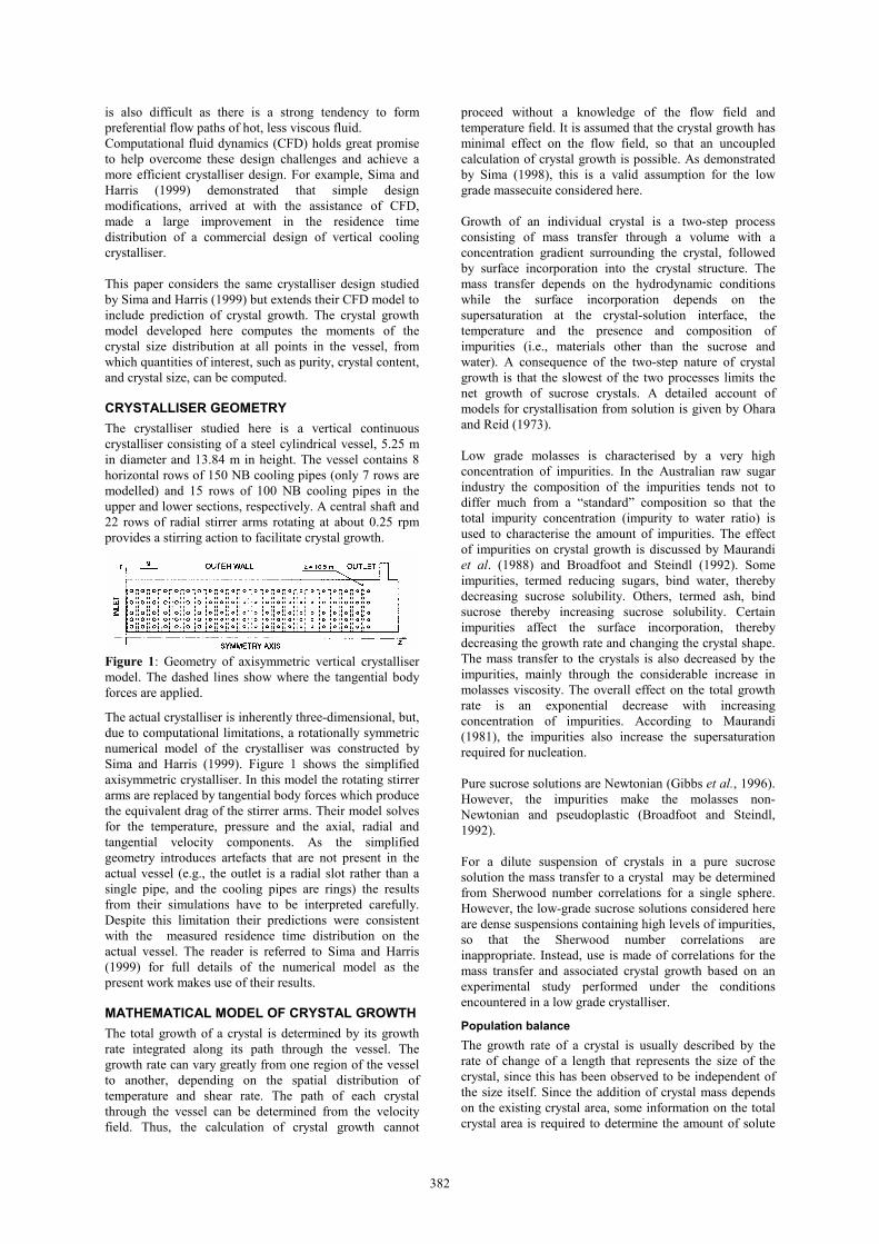
The crystalliser studied here is a vertical continuouscrystalliser consisting of a steel cylindrical vessel, 5.25 min diameter and 13.84 m in height. The vessel contains 8horizontal rows of 150 NB cooling pipes (only 7 rows aremodelled) and 15 rows of 100 NB cooling pipes in theupper and lower sections, respectively. A central shaft and22 rows of radial stirrer arms rotating at about 0.25 rpmprovides a stirring action to facilitate crystal growth.
Figure 1: Geometry of axisymmetric vertical crystallisermodel. The dashed lines show where the tangential bodyforces are applied.
The actual crystalliser is inherently three-dimensional, but,due to computational limitations, a rotationally symmetricnumerical model of the crystalliser was constructed bySima and Harris (1999). Figure 1 shows the simplifiedaxisymmetric crystalliser. In this model the rotating stirrerarms are replaced by tangential body forces which producethe equivalent drag of the stirrer arms. Their model solvesfor the temperature, pressure and the axial, radial andtangential velocity components. As the simplifiedgeometry introduces artefacts that are not present in theactual vessel (e.g., the outlet is a radial slot rather than asingle pipe, and the cooling pipes are rings) the resultsfrom their simulations have to be interpreted carefully.Despite this limitation their predictions were consistentwith the measured residence time distribution on theactual vessel. The reader is referred to Sima and Harris(1999) for full details of the numerical model as thepresent work makes use of their results.
MATHEMATICAL MODEL OF CRYSTAL GROWTH
The total growth of a crystal is determined by its growthrate integrated along its path through the vessel. Thegrowth rate can vary greatly from one region of the vesselto another, depending on the spatial distribution oftemperature and shear rate. The path of each crystalthrough the vessel can be determined from the velocityfield. Thus, the calculation of crystal growth cannot
proceed without a knowledge of the flow field andtemperature field. It is assumed that the crystal growth hasminimal effect on the flow field, so that an uncoupledcalculation of crystal growth is possible. As demonstratedby Sima (1998), this is a valid assumption for the lowgrade massecuite considered here.
Growth of an individual crystal is a two-step processconsisting of mass transfer through a volume with aconcentration gradient surrounding the crystal, followedby surface incorporation into the crystal structure. Themass transfer depends on the hydrodynamic conditionswhile the surface incorporation depends on thesupersaturation at the crystal-solution interface, thetemperature and the presence and composition ofimpurities (i.e., materials other than the sucrose andwater). A consequence of the two-step nature of crystalgrowth is that the slowest of the two processes limits thenet growth of sucrose crystals. A detailed account ofmodels for crystallisation from solution is given by Oharaand Reid (1973).
Low grade molasses is characterised by a very highconcentration of impurities. In the Australian raw sugarindustry the composition of the impurities tends not todiffer much from a “standard” composition so that thetotal impurity concentration (impurity to water ratio) isused to characterise the amount of impurities. The effectof impurities on crystal growth is discussed by Maurandiet al. (1988) and Broadfoot and Steindl (1992). Someimpurities, termed reducing sugars, bind water, therebydecreasing sucrose solubility. Others, termed ash, bindsucrose thereby increasing sucrose solubility. Certainimpurities affect the surface incorporation, therebydecreasing the growth rate and changing the crystal shape.The mass transfer to the crystals is also decreased by theimpurities, mainly through the considerable increase inmolasses viscosity. The overall effect on the total growthrate is an exponential decrease with increasingconcentration of impurities. According to Maurandi(1981), the impurities also increase the supersaturationrequired for nucleation.
Pure sucrose solutions are Newtonian (Gibbs et al., 1996).However, the impurities make the molasses non-Newtonian and pseudoplastic (Broadfoot and Steindl,1992).
For a dilute suspension of crystals in a pure sucrosesolution the mass transfer to a crystal may be determinedfrom Sherwood number correlations for a single sphere.However, the low-grade sucrose solutions considered hereare dense suspensions containing high levels of impurities,so that the Sherwood number correlations areinappropriate. Instead, use is made of correlations for themass transfer and associated crystal growth based on anexperimental study performed under the conditionsencountered in a low grade crystalliser.
Population balance
The growth rate of a crystal is usually described by therate of change of a length that represents the size of thecrystal, since this has been observed to be independent ofthe size itself. Since the addition of crystal mass dependson the existing crystal area, some information on the totalcrystal area is required to determine the amount of solute
383
crystallised and the total crystal volume or mass. It is alsoof interest to predict the sizes of the crystals that areproduced. This information is given by the crystal sizedistribution (CSD). The evolution of the CSD is describedby a population balance equation (Randolph and Larson,1988).
For the purposes of modelling, it is assumed that (1) thereis no nucleation, agglomeration or crystal breakage; (2)the crystals flow with the same velocity as the molasses;and (3) the change in density due to the phase change ofsucrose is negligible. The very high impurityconcentrations in low grade molasses makes thecrystallisation kinetics very slow and the molasses veryviscous. The high viscosities and low velocitiesencountered in a cooling crystalliser make it unlikely thatcrystal breakage occurs. Also, it is considered thatagglomeration (the joining of crystals), which commonlyoccurs at high supersaturation and high growth rates, isunlikely to occur. The assumption of no nucleation isprobably the weakest, as contact nucleation could occur.However, it is uncertain whether the contact or shearforces are large enough to cause contact nucleation, due tothe very high viscosities and low velocities (both relativeand absolute) encountered in a cooling crystalliser. Sincethe crystal settling velocity (8 x 10⁻⁸ m/s for a 0.32 mmcrystal in the molasses considered here) is almost fourorders of magnitude smaller that the characteristicmolasses axial velocity (0.28 mm/s) the secondassumption is justified. The third assumption wasconfirmed by calculating the density change of the mixtureusing the one-dimensional model. It was found to be lessthan 1% during a run with a mean residence time of 16 h.
Given the above assumptions the population balanceequation can be written as
DnDt
= −∂∂L
Gn− DG
∂n∂L
(1)
where D/Dt is the substantial time derivative and n is thepopulation density distribution (per unit mass of mixture).The jth moment of the population density distribution isdefined as
m j = Lj
0
∞
∫ n(L)dL (2)
The zeroth moment is thus the total number of crystals(per unit mass of massecuite), the first moment is the totallength of the crystals, the second moment multiplied bythe area shape factor (ka) is the total surface area, and thethird moment multiplied by the volume shape factor (kv) isthe total volume.
The population balance equation can be transformed intoequations for the moments by multiplying by Lj andintegrating from zero to infinity with respect to L. Bypartial integration, under the assumption that DG isindependent of L and using the boundary conditions ofzero n and ∂n/∂L at L = 0 and at L = ∞, the followingmoment equations are obtained (Sima, 1998)
Dmj
Dt= jGmj −1 + j( j −1)DGmj−2 (3)
for j = 0, 1, 2 and 3. The boundary conditions result fromthe assumptions that no nucleation occurs and that thecrystal size distribution is limited and does not contain any
nuclei. In the above equation DG accounts for crystalgrowth rate dispersion (i.e., for the same conditions not allcrystals grow at the same rate). Growth rate dispersion isimportant if a precise prediction of the crystal sizedistribution is required, or when interpreting growthkinetics from experiments. On the other hand, growth ratedispersion is not a significant feature when determiningthe design or operation of a crystalliser that will producethe maximum growth of the mean crystal size. For thesimulations presented here the growth rate diffusivity isset to zero.
When describing the CSD the mean size and coefficient ofvariation is preferred to the moments. The mean crystalsize is given by
L = m1 / m0 (4)
and the coefficient of variation is defined as
CV =σ / L (5)
where the variance is
σ 2 =1
m0
(L − L )2 n(L ) dL0
∞
∫ =m2
m0
−m1
m0
2
(6)
Mass balance
A knowledge of the sucrose concentration is required todetermine the growth rate, and an equation for sucroseconcentration may be derived from a mass balance. Whencrystallisation takes place, sucrose from the molasses isincorporated into crystals. Since the sucrose crystalsconsist of more than 99.5% sucrose, the crystals areassumed to consist only of sucrose so that all theimpurities remain in the molasses. That is, the increase ofcrystal mass equals the rate of decrease of sucrose mass inthe molasses, which is written as
DSDt
= −1xw
Dxc
Dt (7)
Noting that xc = ρc kv m3, and that the mass of water perunit mass of massecuite (a constant) is
xw =1− ρc kvm3,0
S0
+ I +1 (8)
the sucrose mass balance can be written as
DSDt
= ρ ckvS0 + I +1
1 −ρ ckv m3,0
Dm3
Dt (9)
Growth rate model
The linear growth rate of a crystal is given by thesupersaturation driving force multiplied by a kineticgrowth coefficient (Broadfoot and Steindl, 1992)
G = Kt Csat (Ss − S lim ) (10)
The limiting supersaturation is taken to be the value atwhich no further crystal growth is observed. Theoreticallythe limiting supersaturation is unity, but in this model isslightly greater than one for reasons discussed by Sima(1998). The expression for the total kinetic growthcoefficient, Kt , is
1/ Kt = 1/ Ks + 1/ Kd (11)
where Ks(T, I) and Kd (T, µmo,γ! ) are the kinetic
coefficients for surface incorporation and mass transfer to

384
the crystal, respectively. As can be seen from equation(11), the process which has the smallest kinetic coefficientwill limit the overall growth rate. Empirical correlationsfor the kinetic coefficients, limiting supersaturation andother quantities as functions of the independent variableswere determined experimentally by Broadfoot and Steindl(1992) for parameter ranges that were assumed to berepresentative of the average conditions in a low gradecooling crystalliser. In the absence of more general results,these expressions have been used in this study, eventhough it was necessary to extrapolate outside their rangeof validity to cover the large range of conditionsencountered in the CFD crystal growth model.
NUMERICAL SOLUTION
Equation (3) represents a closed set in terms of themoments of the CSD once the growth rate relationship isspecified. The growth rate depends on the sucroseconcentration, given by equation (9), and the kineticgrowth coefficients, which are functions of the shear rate,viscosity, temperature and other variables obtained from asolution of the mass, momentum and energy transportequations. In this paper these solutions are from Sima andHarris (1999), using their model with unmodifiedgeometry and adiabatic external walls.
The equations that describe crystal growth (equations (3)and (9)) were solved using three general species transportequations in the general purpose Fluid Dynamics AnalysisPackage (FIDAP), making use of a user-definedsubroutine to define the source terms. The existingsolution for the velocity and temperature fields was read inusing the ICNODE(READ) option and used in thecomputation of parameters such as the kinetic growthcoefficients. The transport equations do not contain anydiffusion terms, which causes numerical difficulties inFIDAP. For this reason small diffusion coefficients (oforder 10-9 m2/s) were introduced into each equation tofacilitate the solution. The FIDAP solution method wasvalidated against an analytical two-dimensional channelflow model that included crystal growth by Sima (1998).
One-dimensional model
A simplified model, analogous to that developed byBroadfoot and Steindl (1992) was also prepared. Thismodel integrates the one-dimensional form of the momentequations with respect to time. The model requires theinitial (inlet) conditions and residence time to be specified,along with temperature and shear rate profiles. Numericalintegration of the governing ODEs is carried out usingEngineering Equation Solver (EES). Since it runsextremely quickly, this model is useful for carrying outparametric studies to investigate the effect of globalparameters such as the temperature profile and shear rate.For example, Broadfoot and Steindl used their model todetermine optimum cooling profiles for maximumexhaustion (i.e., extraction of sucrose).
RESULTS AND DISCUSSION
Many of the features of crystal growth are determined bythe residence time distribution, which is related to thevelocity field. The present vessel has a poor residence timedistribution, with major short circuiting of virtuallyuncooled massecuite down the region adjacent to the outerwall for reasons discussed by Sima and Harris (1999).This hot, fast moving massecuite has insufficient residence
time for much crystal growth to occur. Conversely, there isan area of cool, very viscous massecuite in the regionsurrounding the inner three columns of cooling pipes. Thismassecuite has a long residence time (2–3 days)compared to the mean (11 h) and so has ample time forcrystal growth.
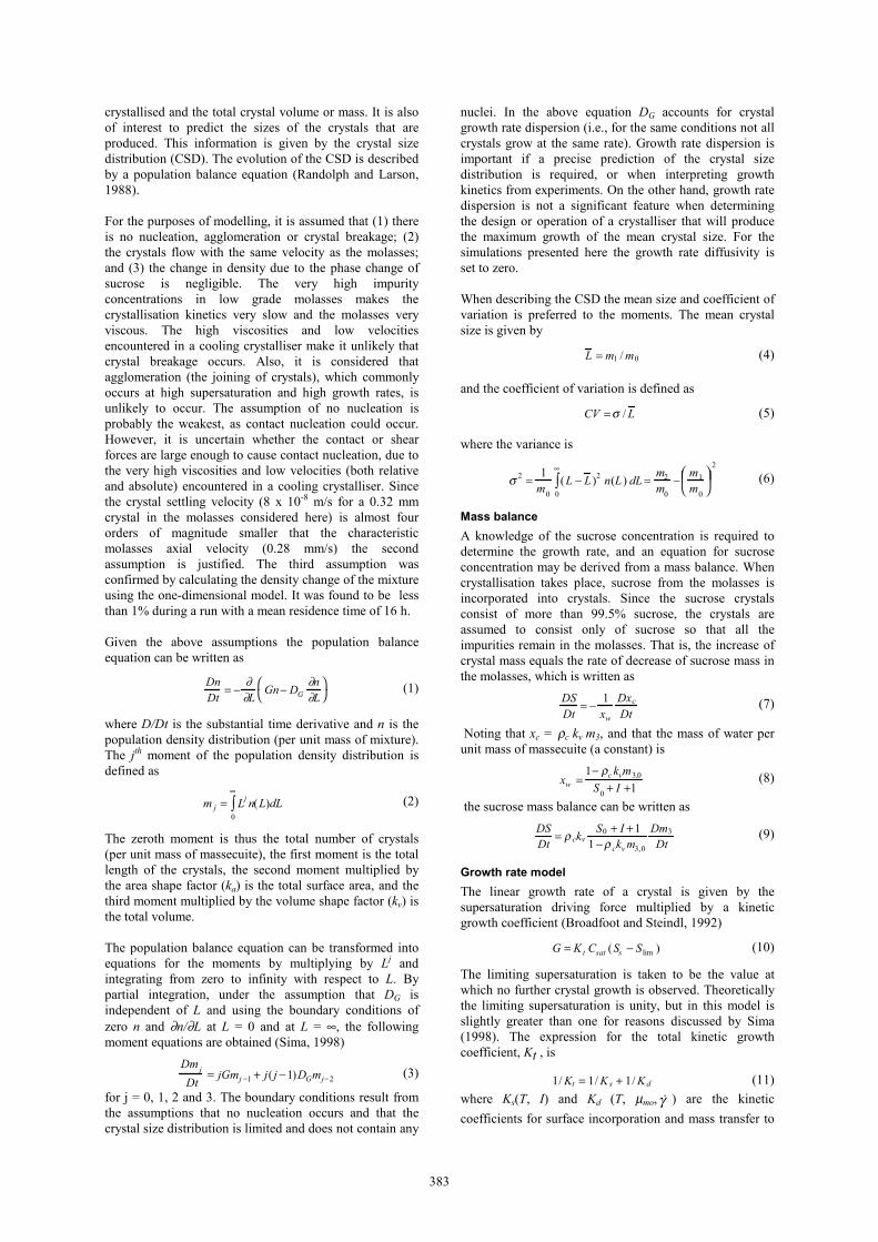
An important parameter that measures sucrose extractionis molasses purity, P, which is a measure of sucroseconcentration in the molasses. A shaded contour plot ofthe computed purity distribution is shown in Fig. 2. Thelowest purity level (i.e., highest sucrose extraction) occursin the region where the velocity is slowest and thetemperature is the lowest. However, these low purityvalues make an almost insignificant contribution to themass-averaged purity leaving the outlet. The majorcontribution to the outlet purity is from the fast moving,high temperature, high purity region adjacent to the outerwall. The net result is that the predicted overall puritydecrease is not as large as would be expected in a properlyfunctioning cooling crystalliser.
Figure 2: Molasses purity distribution. The lightest shaderepresents the inlet purity (47%) and the darkest shaderepresents the minimum purity (36%).
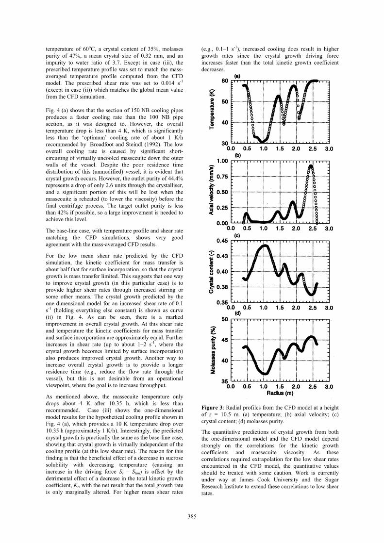
Radial profiles from the CFD model at an axial distance of10.5 m from the inlet (refer to Fig. 1) are presented in Fig.3. This vertical location was selected as it is close to theoutlet, but is not unduly influenced by the changed flowdirection at the outlet. The corresponding residence timeat this vertical location is 10.35 h. Figs. 3 (a) and (b)illustrate that a significant fraction of the massecuitemoves rapidly down the outer part of the vessel withminimal cooling (i.e., the temperature at r = 2.5 m is stillvirtually equal to the inlet temperature). This undesirablebehaviour results in a poor residence time distributionwith a peak at around 3.2 h, significantly lower than themean residence time of 10.35 h at this location. The regionof the vessel around r = 1 m receives excessive coolingwhich leads to a large region of very viscous, virtuallystagnant massecuite. In this essentially stagnant region,which has a residence time of 2–3 days, the crystal contentis very high and the molasses purity is very low, sincecrystal growth has a long time to occur. The opposite istrue in the fast moving outer region, in which there isinsufficient time to achieve the desired amount of sucroseextraction. Since it occupies a large part of the cylindricalcrystalliser volume and moves with high axial velocity theouter region makes the major contribution to the overallmass-averaged crystal growth.
The overall performance of the crystalliser is illustrated inFig. 4. The open symbols are radially mass-averagedresults computed from the FIDAP CFD model using
φ = φ uzri
ro
∫ rdr / uzri
ro
∫ rdr (12)
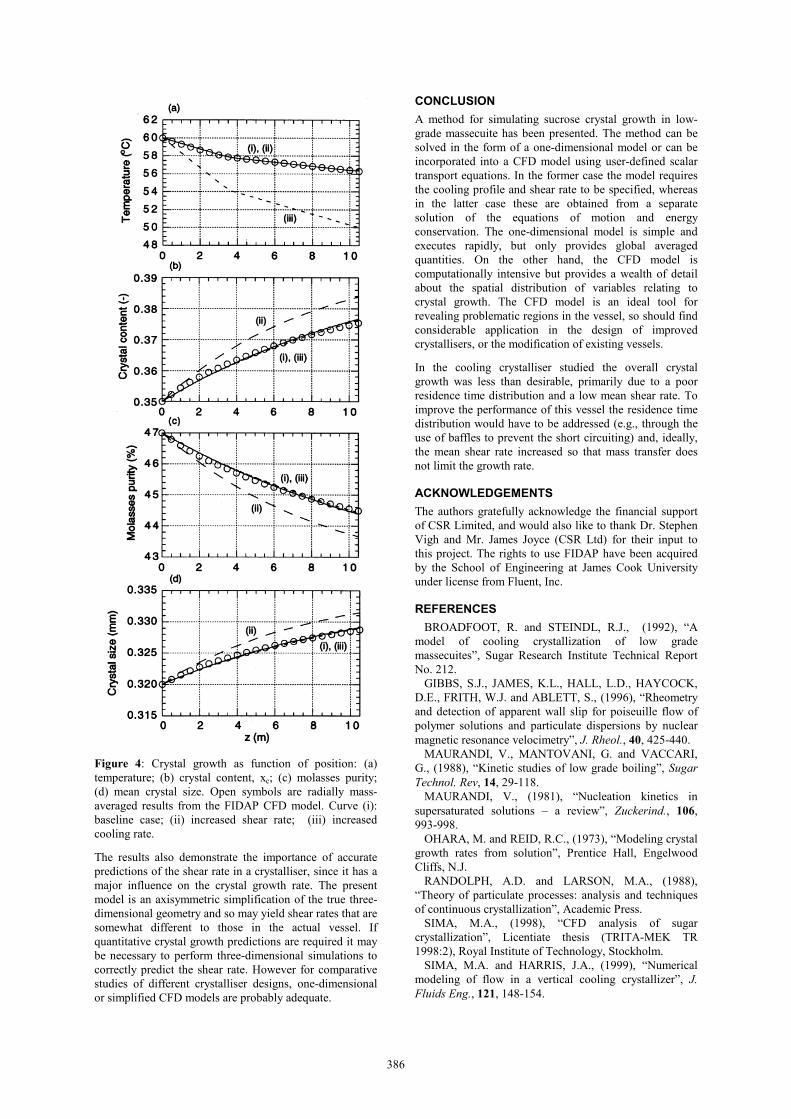
where φ represents the quantity to be mass-averaged (e.g.,temperature). The three curves shown in Fig. 4 representdifferent runs of the one-dimensional crystal growthmodel. In each case the prescribed inlet conditions are a
385
temperature of 60oC, a crystal content of 35%, molassespurity of 47%, a mean crystal size of 0.32 mm, and animpurity to water ratio of 3.7. Except in case (iii), theprescribed temperature profile was set to match the mass-averaged temperature profile computed from the CFDmodel. The prescribed shear rate was set to 0.014 s-1
(except in case (ii)) which matches the global mean valuefrom the CFD simulation.
Fig. 4 (a) shows that the section of 150 NB cooling pipesproduces a faster cooling rate than the 100 NB pipesection, as it was designed to. However, the overalltemperature drop is less than 4 K, which is significantlyless than the ‘optimum’ cooling rate of about 1 K/hrecommended by Broadfoot and Steindl (1992). The lowoverall cooling rate is caused by significant short-circuiting of virtually uncooled massecuite down the outerwalls of the vessel. Despite the poor residence timedistribution of this (unmodified) vessel, it is evident thatcrystal growth occurs. However, the outlet purity of 44.4%represents a drop of only 2.6 units through the crystalliser,and a significant portion of this will be lost when themassecuite is reheated (to lower the viscosity) before thefinal centrifuge process. The target outlet purity is lessthan 42% if possible, so a large improvement is needed toachieve this level.
The base-line case, with temperature profile and shear ratematching the CFD simulations, shows very goodagreement with the mass-averaged CFD results.
For the low mean shear rate predicted by the CFDsimulation, the kinetic coefficient for mass transfer isabout half that for surface incorporation, so that the crystalgrowth is mass transfer limited. This suggests that one wayto improve crystal growth (in this particular case) is toprovide higher shear rates through increased stirring orsome other means. The crystal growth predicted by theone-dimensional model for an increased shear rate of 0.1s-1 (holding everything else constant) is shown as curve(ii) in Fig. 4. As can be seen, there is a markedimprovement in overall crystal growth. At this shear rateand temperature the kinetic coefficients for mass transferand surface incorporation are approximately equal. Furtherincreases in shear rate (up to about 1–2 s-1, where thecrystal growth becomes limited by surface incorporation)also produces improved crystal growth. Another way toincrease overall crystal growth is to provide a longerresidence time (e.g., reduce the flow rate through thevessel), but this is not desirable from an operationalviewpoint, where the goal is to increase throughput.
As mentioned above, the massecuite temperature onlydrops about 4 K after 10.35 h, which is less thanrecommended. Case (iii) shows the one-dimensionalmodel results for the hypothetical cooling profile shown inFig. 4 (a), which provides a 10 K temperature drop over10.35 h (approximately 1 K/h). Interestingly, the predictedcrystal growth is practically the same as the base-line case,showing that crystal growth is virtually independent of thecooling profile (at this low shear rate). The reason for thisfinding is that the beneficial effect of a decrease in sucrosesolubility with decreasing temperature (causing anincrease in the driving force Ss – Slim) is offset by thedetrimental effect of a decrease in the total kinetic growthcoefficient, Kt, with the net result that the total growth rateis only marginally altered. For higher mean shear rates
(e.g., 0.1–1 s-1), increased cooling does result in highergrowth rates since the crystal growth driving forceincreases faster than the total kinetic growth coefficientdecreases.
Figure 3: Radial profiles from the CFD model at a heightof z = 10.5 m. (a) temperature; (b) axial velocity; (c)crystal content; (d) molasses purity.
The quantitative predictions of crystal growth from boththe one-dimensional model and the CFD model dependstrongly on the correlations for the kinetic growthcoefficients and massecuite viscosity. As thesecorrelations required extrapolation for the low shear ratesencountered in the CFD model, the quantitative valuesshould be treated with some caution. Work is currentlyunder way at James Cook University and the SugarResearch Institute to extend these correlations to low shearrates.
386
Figure 4: Crystal growth as function of position: (a)temperature; (b) crystal content, xc; (c) molasses purity;(d) mean crystal size. Open symbols are radially mass-averaged results from the FIDAP CFD model. Curve (i):baseline case; (ii) increased shear rate; (iii) increasedcooling rate.
The results also demonstrate the importance of accuratepredictions of the shear rate in a crystalliser, since it has amajor influence on the crystal growth rate. The presentmodel is an axisymmetric simplification of the true three-dimensional geometry and so may yield shear rates that aresomewhat different to those in the actual vessel. Ifquantitative crystal growth predictions are required it maybe necessary to perform three-dimensional simulations tocorrectly predict the shear rate. However for comparativestudies of different crystalliser designs, one-dimensionalor simplified CFD models are probably adequate.
CONCLUSION
A method for simulating sucrose crystal growth in low-grade massecuite has been presented. The method can besolved in the form of a one-dimensional model or can beincorporated into a CFD model using user-defined scalartransport equations. In the former case the model requiresthe cooling profile and shear rate to be specified, whereasin the latter case these are obtained from a separatesolution of the equations of motion and energyconservation. The one-dimensional model is simple andexecutes rapidly, but only provides global averagedquantities. On the other hand, the CFD model iscomputationally intensive but provides a wealth of detailabout the spatial distribution of variables relating tocrystal growth. The CFD model is an ideal tool forrevealing problematic regions in the vessel, so should findconsiderable application in the design of improvedcrystallisers, or the modification of existing vessels.
In the cooling crystalliser studied the overall crystalgrowth was less than desirable, primarily due to a poorresidence time distribution and a low mean shear rate. Toimprove the performance of this vessel the residence timedistribution would have to be addressed (e.g., through theuse of baffles to prevent the short circuiting) and, ideally,the mean shear rate increased so that mass transfer doesnot limit the growth rate.
ACKNOWLEDGEMENTS
The authors gratefully acknowledge the financial supportof CSR Limited, and would also like to thank Dr. StephenVigh and Mr. James Joyce (CSR Ltd) for their input tothis project. The rights to use FIDAP have been acquiredby the School of Engineering at James Cook Universityunder license from Fluent, Inc.
REFERENCES
BROADFOOT, R. and STEINDL, R.J., (1992), “Amodel of cooling crystallization of low grademassecuites”, Sugar Research Institute Technical ReportNo. 212.
GIBBS, S.J., JAMES, K.L., HALL, L.D., HAYCOCK,D.E., FRITH, W.J. and ABLETT, S., (1996), “Rheometryand detection of apparent wall slip for poiseuille flow ofpolymer solutions and particulate dispersions by nuclearmagnetic resonance velocimetry”, J. Rheol., 40, 425-440.
MAURANDI, V., MANTOVANI, G. and VACCARI,G., (1988), “Kinetic studies of low grade boiling”, SugarTechnol. Rev, 14, 29-118.
MAURANDI, V., (1981), “Nucleation kinetics insupersaturated solutions – a review”, Zuckerind., 106,993-998.
OHARA, M. and REID, R.C., (1973), “Modeling crystalgrowth rates from solution”, Prentice Hall, EngelwoodCliffs, N.J.
RANDOLPH, A.D. and LARSON, M.A., (1988),“Theory of particulate processes: analysis and techniquesof continuous crystallization”, Academic Press.
SIMA, M.A., (1998), “CFD analysis of sugarcrystallization”, Licentiate thesis (TRITA-MEK TR1998:2), Royal Institute of Technology, Stockholm.
SIMA, M.A. and HARRIS, J.A., (1999), “Numericalmodeling of flow in a vertical cooling crystallizer”, J.Fluids Eng., 121, 148-154.