Mixing and Crystallisation - Crystallization Systems · PDF fileAgenda Mixing basics Mixing...
86
Mixing and Crystallisation December 2, 2015
Transcript of Mixing and Crystallisation - Crystallization Systems · PDF fileAgenda Mixing basics Mixing...

Mixing and CrystallisationDecember 2, 2015

Thank You to Our Sponsors
2

AgendaMixing basicsMixing and scale downCrystallisation introductionCrystallisationCase studyCase studyFlow Crystallisation
3

Mixing BasicsSolutions and slurries need to be stirred to allow good mixing of the various components in thegood mixing of the various components in the mixture and for good heat transferThe type of stirrer / agitator and the shape of the vessel will affect the motion of the solution and / or slurry and so the mixing taking placeLab equipment tends to be spherical – round-bottomed flasksPlant equipment is usually cylindricala t equ p e t s usua y cy d caPlant vessels are usually baffled
4

Flow Pattern in an Unbaffled Tank
Vortex
Swirl
5

Flow Pattern in a Baffled Tank
Baffles
6

Mass Transfer and Agitation
Type of agitation affects motion in solution and effectiveness of mass transferDesign of agitator may be importantg g y p
Impeller, Anchor, Turbine ?Number of bladesDiameterPitch anglePitch angleDistance from bottomWidth of baffle(s)Width of baffle(s)
7

Suspending Solids
8Scientific Update course: Physicochemical Concepts in Process Development,presented by Dr N. Powles and Dr M. Stirling (University of Huddersfield).
HCl Neutralisation with KOH:U b ffl dUnbaffled
9Scientific Update course: Physicochemical Concepts in Process Development,presented by Dr N. Powles and Dr M. Stirling (University of Huddersfield).

HCl Neutralisation with KOH:B ffl dBaffled
10Scientific Update course: Physicochemical Concepts in Process Development,presented by Dr N. Powles and Dr M. Stirling (University of Huddersfield).

Mixing Varies Across the VesselThe very best mixing takes place right by the tip of the agitatorof the agitatorPoor mixing zones can be found at the bottom of the vessel and on the surface of the liquidAddition point for chemical reactions, salt formations, and anti-solvent crystallisations can be criticalSub-surface via a dip pipe is often the best option if mixing is criticalopt o g s c t caAddition on to the surface can be improved by using a spray nozzleusing a spray nozzle
11

Mixing and AgitatorsThe motion of the liquid / slurry in the vessel will affect the mixingaffect the mixingThe motion of the liquid / slurry is directly affected by the agitator / stirrer being usedHow much radial mixing (sideways) and axial mixing (up and down) takes place in the vessel will depend on the position and design of the agitator
12
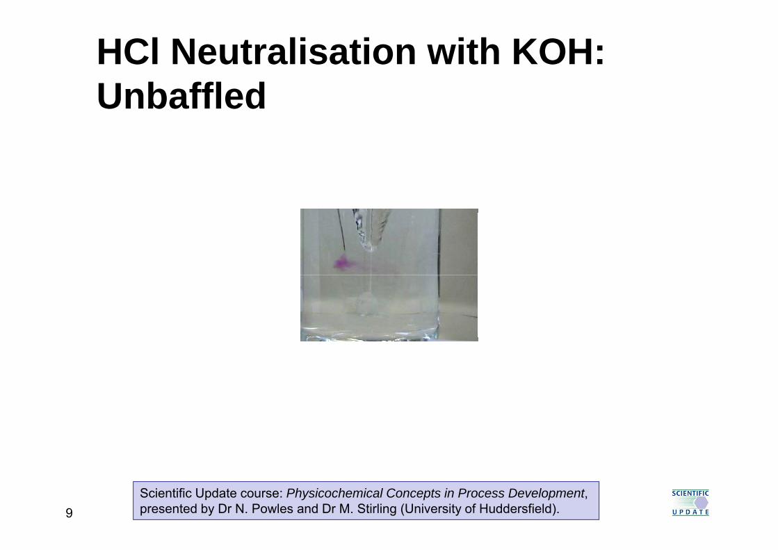
Impeller
3 radial and curved bladesAssembled axially with 1-2 bafflesA i l ti d di l flAxial suction and radial flowApplication rangeperipheral speedperipheral speed 0.5-10 m/s - turbine flowServiceService
homogenizationsuspension of solids
&liquid-liquid & solid-liquid dispersionheat transferchemical reaction
13

Anchor
Anchor agitatorAssembled axially without baffle or with one thermopocketthermopocketAxial suction and radial flow with rotation of product pApplication rangeperipheral speed 0.5-5 m/s -t it l i fltransitory or laminar flowService
homogenizationhomogenizationheat transferchemical reaction
14

Radial Turbine
Flat parallel blade to giveFlat parallel blade to give high radial flow and obtain high mix shearhigh mix shear
15

Uniflow Axial Turbine
Pitched blades to give high axial flow& l h& low shearTapered blade to minimize radial flow and maintain constant mix velocity at blade tipShear mix minimized3 blades give ease of installation3 blades give ease of installation through centre openingAssembled with or without bafflesApplication range: per speed 2 5 m/sApplication range: per. speed 2-5 m/sService
homogenizationsuspension of solidsliquid-solid & gas-liquid dispersionheat transfer
16
chemical reaction

Twin Agitator
Several 2-bladed wheels 90o
drotatedAssembled with or without bafflebafflePrevailing flow axial Application rangeApplication rangeperipheral speed 0.5-12 m/s -laminar or turbulent flowService
homogenizationliquid-liquid & solid-liquidliquid-liquid & solid-liquid dispersionheat transfer
17

Pitched Turbine
4 or 6-bladed propellerAssembled axially with 1-4 beaver-tail baffles or eccentrically without baffleeccentrically without bafflePrevailing flow axialApplication rangeApplication rangeperipheral speed 3-20 m/s -turbulent flowService
homogenizationsuspension of solidssuspension of solidsliquid-liquid, solid-liquid & gas-liquid dispersionh t t f
18
heat transfer

Disc Turbine
Turbine wheel with 6 radial bladesAssembled axially with or without1-4 beaver-tail baffles. Axial suction and radial flowAxial suction and radial flowApplication rangeperipheral speed 3-10 m/s –transitory or turbulent flowService
homogenizationhomogenizationsuspension of solidsliquid-liquid, solid-liquid & gas-liquid dispersiondispersionemulsionchemical reactionheat transfer
19
heat transfer
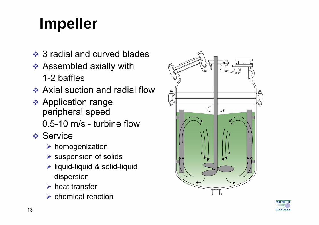
Loop Agitator
Tubular gate agitatorAssembled axially without baffle or with one thermopocketthermopocketCentripetal and centrifugal radial flowApplication rangeperipheral speed 3-5 m/s -t it l i fltransitory or laminar flowService
homogenization of viscoushomogenization of viscous productsheat transferh i l ti
20
chemical reaction

Less Common Impeller Types
StabilizedFlat-Blade
T bi
PerforatedPropeller
Saw-ToothedPropeller
Studded Cage
Turbinep p g
Beater
21Scientific Update course: Secrets of Batch Process Scale Up,given by F. McConville (FXM Engineering).

SpinChem Rotating Flow Cell
22 C.-J. Aurell et al (AstraZeneca), Org. Proc. Res. Dev., 2014, 18, 1116.

SpinChem Rotating Flow Cell
23 C.-J. Aurell et al (AstraZeneca), Org. Proc. Res. Dev., 2014, 18, 1116.

SpinChem Video
24 www.spinchem.com

Impeller Diameters
Ratio of impeller diameter to vessel diameter is an important factor in scale upimportant factor in scale-up
To disperse a gas in a liquid, optimum ratio is approximately 0.25pp yTo disperse 2 immiscible liquids, optimum ratio is approximately 0.40To blend 2 miscible liquids, optimum ratio is > 0.60
Where a gas is introduced to a solid-liquid dispersion a complex situation arisescomplex situation arises.
Gas bubbling may lead to poor mass transfer, whereas in absence of gas, mixing was good with thewhereas in absence of gas, mixing was good with the same agitator.
On scale-up, KEEP GEOMETRIC SIMILARITY!
25Handbook of Industrial Mixing, ed. E.L. Paul, V.A. Atiemo-Obengand S.M. Kresta, Wiley-Interscience, 2004, ISBN 0-471-26919-0

Laminar or Turbulent Flow ?
Osborne Reynolds (1883) distinguished betweenOsborne Reynolds (1883) distinguished between two types of flow
laminar - pressure drop proportional to vp p p pturbulent - pressure drop proportional to v2
The feature of turbulence is formation of lots of eddies of varying sizes, vital for good mixingDegree of turbulence can be characterized by a g yquantity called the “Reynolds number” NReFor scale-up, if pilot vessel designed so that NRep p g Reis the same as in the lab, then equivalent mixing is likely
26

Reynolds Number NRe
For agitated vesselN ND2 /NRe = ND2ρ/μ
D = diameter of impeller (m)N = rotation speed of impeller (s-1)ρ = density (kg.m-3)
1 1μ = viscosity (kg.m-1.s-1)NRe has NO dimensionsChange from laminar to turbulent flow usually occurs around same values of NRe
NRe < 4,000 laminarNRe > 10,000 turbulent
27

Viscosity and Mass Transfer
For high viscosity applications (NRe up to 5000)g y ( Re )Large scale diameter agitatorLow speedi.e. anchor stirrer
For low viscosity fluidsDiameter of agitator may be as low as one third vessel diameterHi h dHigh speed
Propeller type agitators induce axial flowTurbines induce radial flowTurbines induce radial flowAxial flow component increased by angling turbine blades
28
turbine blades

Macromixing (Bulk Mixing)
Achieves a uniform blend on a large scaleAchieves a uniform blend on a large scaleBulk mixing times:
500 ml flask (500 rpm) 2 - 3 seconds( p )40 m3 vessel (25 rpm) 30 - 60 seconds
Before complete mixing occurs there may be“local” excesses of reagentpH differences across mixture
f fThis may cause formation of by-productsparticularly if rate of by-product formation is comparable to that of main reactioncomparable to that of main reaction
Therefore, selectivity may change with scale
29
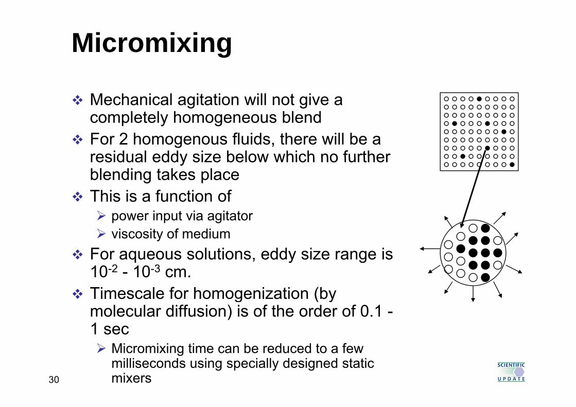
Micromixing
Mechanical agitation will not give a l l h bl dcompletely homogeneous blend
For 2 homogenous fluids, there will be a residual eddy size below which no furtherresidual eddy size below which no further blending takes placeThis is a function of
power input via agitatorviscosity of medium
F l ti dd i iFor aqueous solutions, eddy size range is 10-2 - 10-3 cm.Timescale for homogenization (byTimescale for homogenization (by molecular diffusion) is of the order of 0.1 -1 sec
30
Micromixing time can be reduced to a few milliseconds using specially designed static mixers

Ei Mixing Energy Dissipation
A measure of power/unit massput into mixing fluid(dissipation of turbulent kinetic energy)Values range from
0 to ~3.5 W/kgg
3 5PN N dE =
Perhaps most useful parameter
iEV
=
Perhaps most useful parameterfor “scale-down” experiments
31
Where: d = impeller diameter (m) N = rotational speed (sec-1)NP = power number V = volume (m3)

Ei Mixing Energy Dissipation
kgw
mdNN
VdNN
massPowerEi PP ====
5353 ρ
Another commonly used quantity:
kgmVmass
Another commonly used quantity:
53 wdNNPowerP P ρ3mVvolumeV
P ===ρ
Where: d = impeller diameter (m) N = rotational speed (sec-1)N = power number V = volume (m3)
32
NP = power number V = volume (m3)ρ = density (kg/m3)

Mixing Configuration:S i B t h R tSemi-Batch Reactors
Dip Pipe
33

CrystallisationCrystallisation
34
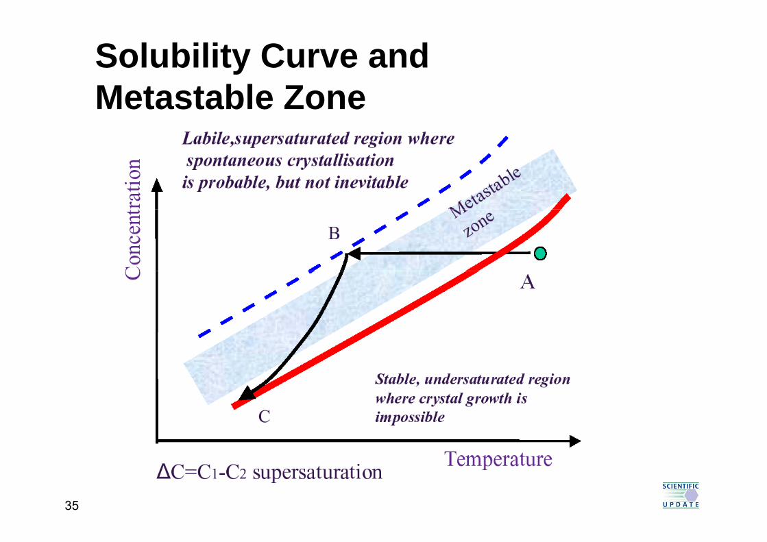
Solubility Curve and M t t bl ZMetastable Zone
35

Cooling Profiles
a Natural cooling ⎟⎠⎞
⎜⎝⎛−=
−
−
τθθθθ t
ff exp
b Linear cooling
c Controlled cooling
⎠⎝ τθθ fo
( )⎥⎥⎤
⎢⎢⎡
⎟⎠⎞
⎜⎝⎛
Δ−−=
3tTfTTT oog
Natural
( )⎥⎥⎦⎢
⎢⎣ ⎠⎝ Δt
foo
T
b
cC
cooling
Linear
tura
ion
a
ba b c Controlled
supe
rsa
time
a
Temp Time
G Steele (AZ), presentation at Process AnalyticalTechnology Conference, Clearwater FL, November 200736

During CrystallisationNucleation rate affected by
Agitation rateAgitation rateSupersaturation levelSeedinggTrace impuritiesTemperature
Rate of crystal growth affected byAgitation rategDensity and viscosity of solventTemperatureTrace impurities
Optimum temperature for nucleation may
37
not be the optimum for crystal growthReview on nucleation: R.J. Davey et al, Angew. Chem. Int. Ed., 2013, 52, 2166.

NucleationSpontaneous appearance of tiny “embryos” of solid phase
< 1 μm; too small for visual detectionClassical nucleation theory (CNT)
B = A exp -16π3γ3ϖ2
B0 = A exp γ
3R3T3(lnS)2
B0 - nucleation rate (m-3s-1)A - pre-exponential factorp e e po e t a actoγ - interfacial tension (dn m-2)ϖ - molecular volume (m3)R - Gas constantT - Temperature (K)
R. Davey & J. Garside; From Molecules to Crystallizers, OUP 2000, pp 17 – 18Angew. Chem. Int. Ed., 2013, 52, 2166
p ( )S - Relative supersaturation (C/Ceq)
g , , ,
Measurement of Induction Time tind(tind = 1 / B0)
Delay between creation of supersaturation andDelay between creation of supersaturation and appearance of detectable particlestind decreases exponentially with increasing S
38

Two-Step Nucleation Mechanism
Nucleation occurs inside pre-pformed metastable clusters (several hundred nanometers) C t ti i hi h thConcentration is higher than in the bulk solution, but still no order to the molecules (spinodal phase)Accounts better for observed
t f l ti hi hrates of nucleation, which are about 1010 time lower than CNT would predict pSee P.G. Vekilov, Cryst. Growth Des., 2010, 10, 5007–5019
39
5019
Primary Nucleation
HomogeneousS t f lid h f l tiSpontaneous appearance of solid phase from solutionRequires very high degree of supersaturation
HeterogeneousInduced by foreign particles at moderate supersaturation levelsLab solutions contain >106 foreign particles per cm3
b l 1 ibelow 1 micronFiltration removes foreign particles (to below 103 / cm3) thus making primary nucleation more difficultcm3), thus making primary nucleation more difficult
40
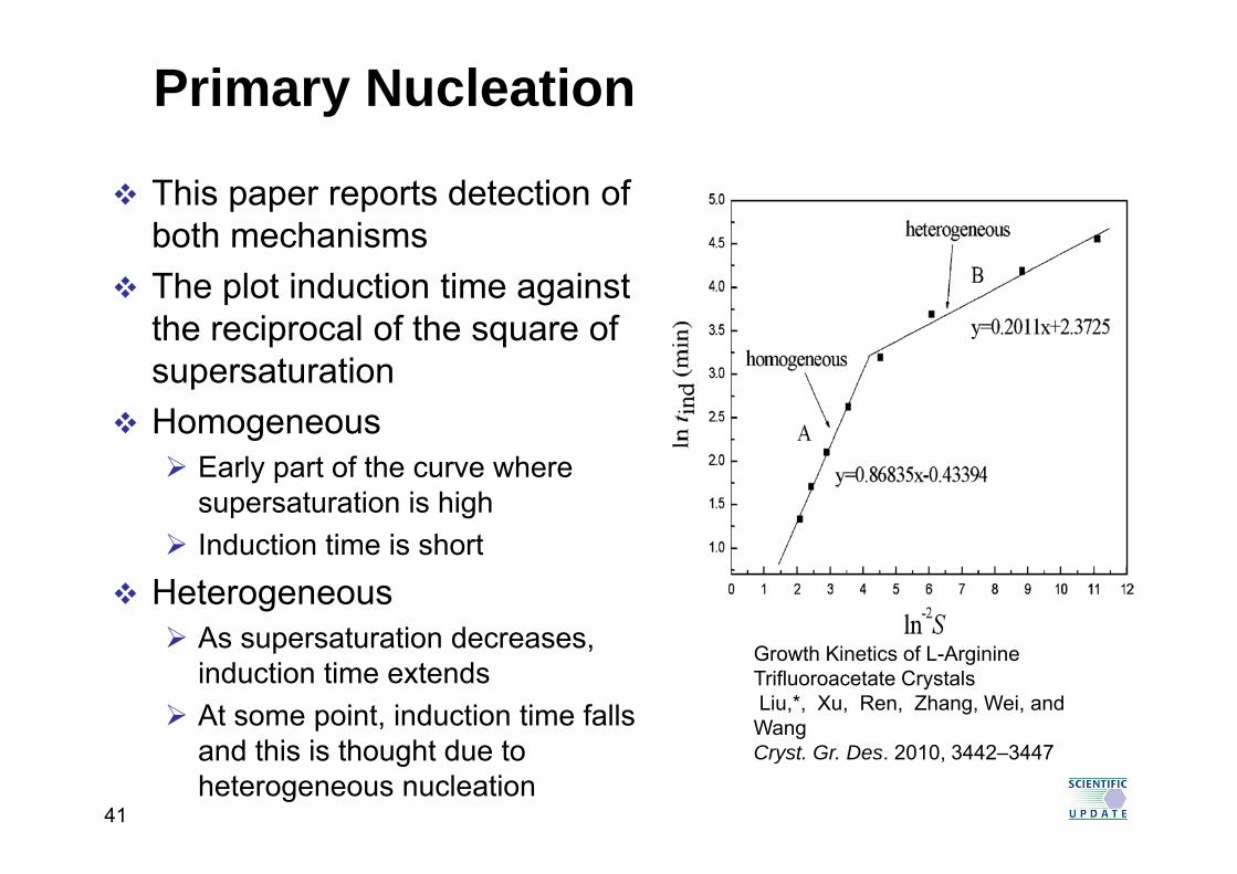
Primary Nucleation
This paper reports detection of both mechanismsboth mechanismsThe plot induction time against the reciprocal of the square ofthe reciprocal of the square of supersaturationHomogeneousg
Early part of the curve where supersaturation is highI d ti ti i h tInduction time is short
Heterogeneous As supersaturation decreasesAs supersaturation decreases, induction time extendsAt some point, induction time falls
Growth Kinetics of L-Arginine Trifluoroacetate Crystals Liu,*, Xu, Ren, Zhang, Wei, and Wang
and this is thought due to heterogeneous nucleation
a gCryst. Gr. Des. 2010, 3442–3447
41

Late Appearance of a Hydrate
NCH3O OCH3
O
N
F
NH
NH
N
4 Solvates and 1 anhydrate known10 Batches of anhydrate produced in a seeded
F
10 Batches of anhydrate produced in a seeded crystallisation
Slurry seeds for 1-2 hours, followed by stirring at room y y gtemperatureGives needles
N d tiNew seed preparationSonicate the seeds for 20 minutes, followed by stirring at room temperaturetemperature
42H. Morrison et al (Amgen), Org. Proc. Res. Dev., ASAPDOI:10.1021/acs.oprd.5b00030, published online on June 26, 2015.

Seeds and Final Cake
Morphology – rods not needlesFaster filtration, lower solubility
43H. Morrison et al (Amgen), Org. Proc. Res. Dev., ASAPDOI:10.1021/acs.oprd.5b00030, published online on June 26, 2015.
Faster filtration, lower solubility

Thermal Analysis
44H. Morrison et al (Amgen), Org. Proc. Res. Dev., ASAPDOI:10.1021/acs.oprd.5b00030, published online on June 26, 2015.

Analysis of the New FormAnhydrate shows no weight lossNew form shows weight loss of 2.6% on heating from room temperature to 130°CKF on new form gives 2.3 wt% waterThis corresponds to a hemi-hydrateThis corresponds to a hemi hydrateThe hemi-hydrate loses water at 77.6°C and then crystallises as a new anhydrous form atthen crystallises as a new anhydrous form at 145.1°CThis melts at 184 2°C and is a new polymorphThis melts at 184.2°C and is a new polymorphThis is confirmed by variable temperature XRPD
45H. Morrison et al (Amgen), Org. Proc. Res. Dev., ASAPDOI:10.1021/acs.oprd.5b00030, published online on June 26, 2015.

Variable Temperature XRPD
46H. Morrison et al (Amgen), Org. Proc. Res. Dev., ASAPDOI:10.1021/acs.oprd.5b00030, published online on June 26, 2015.

Increasing the Dissolution Rate1. Unmilled hydrate2 Pin-milled x 12. Pin-milled x 13. Pin-milled x 44. Jet-milled x 1
Surface area (m2/g)1 0 51. 0.52. 0.83 3 33. 3.34. 3.35. 6.9 (anhydrate)
47H. Morrison et al (Amgen), Org. Proc. Res. Dev., ASAPDOI:10.1021/acs.oprd.5b00030, published online on June 26, 2015.

Metastable Zone WidthVaries with
Cooling rateCooling rateAgitation rateVessel sizeVessel sizeImpuritiesPresence of particlesPresence of particlesThermal history of the solution
Width of metastable zone is independent ofWidth of metastable zone is independent of crystallisation technique
Comparable values for evaporative and cooling p p gcrystallisations
48

Effect of Cooling Rate
Crystallisation of L-Glutamic Acid in an oscillatory baffled crystalliserMSZW id t hi h li tMSZW wider at higher cooling rates
X. Ni et al, Cryst. Gr. Des., 2008, 8, 2875-288149
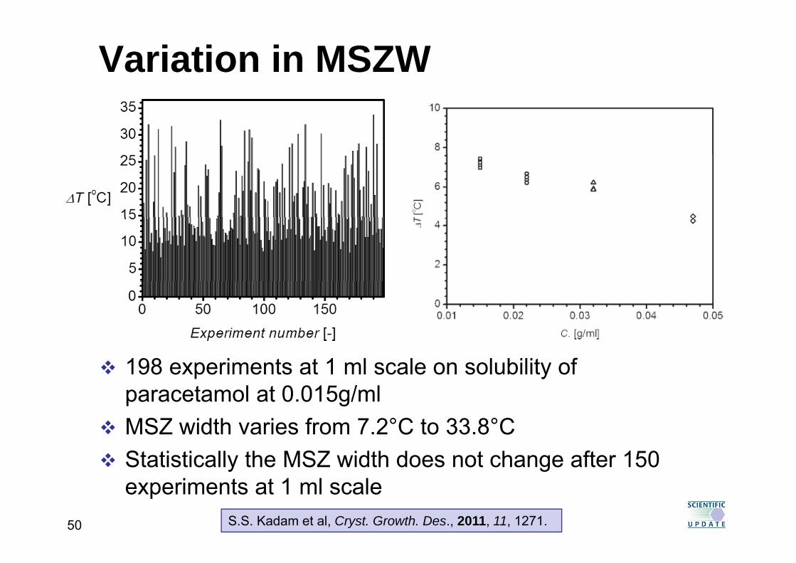
Variation in MSZW
198 experiments at 1 ml scale on solubility of paracetamol at 0.015g/mlMSZ width varies from 7.2°C to 33.8°CStatistically the MSZ width does not change after 150 experiments at 1 ml scale
50 S.S. Kadam et al, Cryst. Growth. Des., 2011, 11, 1271.

Effect of Vessel SizeEmphasises that nucleation is
a random processI 1 L l th h fIn 1 mL volume, the chance of
observing nucleation at 7 degrees is very low perhapsdegrees is very low, perhaps 0.1%
But in 1 litre, the number of molecules is a thousand fold greater, so the chance of b i l ti i l
Probability distribution of the MSZW ∆T for a paracetamolconcentration of 0 015 g/mL in water at a
observing nucleation is also multiplied a thousand fold to around 100% concentration of 0.015 g/mL in water at a
cooling rate of 0.5 C/min:squares, 1mL experiments; circles, 1 L experiments.
around 100%For the MSZW, you really
need a larger reactor
S.S. Kadam et al, Cryst. Growth. Des., 2011, 11, 1271.51

Agitation RateMost agitated solutions nucleate spontaneously at lower degrees of supersaturation thanat lower degrees of supersaturation than quiescent ones (i.e. width of metastable zone is reduced!)reduced!)Increased agitation USUALLY causes additional secondary nucleation by seed proliferation andsecondary nucleation by seed proliferation and attritionFaster agitation may enhance growth kinetics,Faster agitation may enhance growth kinetics, particularly in viscous mediaLarge crystals (e.g. for XRD) normally require a ge c ysta s (e g o ) o a y equ equiescent conditions
52

Influence of Addition Rate and Stirring RateStirring Rate
Investigation of an API Crystallisation Zone width decreases slightly at higher agitation rateZone width decreases slightly at higher agitation rateZone width increases at higher addition rate
0 3
0.4
475 rpm - impeller addition location
325 rpm impeller addition location
0.2
0.3
er/g
eth
anol
)
0.1
SZW
(g w
ate
Addition close to impeller
-0.1
0.00 0.1 0.2 0.3 0.4 0.5
MS
53D. O’Grady (Mettler Toledo); PAT in Organic Process R&D,Clearwater FLA, Nov 2007; Chem Eng Res Des, 2007, 85, 945.
Addition Rate (g water/s )

Importance of Point of Addition
0.3
0.4
nol)
475 rpm - wall addition location
325 rpm - wall addition location0.3
0.4
nol)
475 rpm - impeller addition location
325 rpm impeller addition location
Additi l t l ll
0.1
0.2
(g w
ater
/g e
than
0.1
0.2
g w
ater
/g e
than Addition close to vessel wall
Addition close to impeller
0 1
0.00 0.1 0.2 0.3 0.4 0.5
MSZ
W (
0.00 0.1 0.2 0.3 0.4 0.5
MSZ
W (g
-0.1
Addition Rate (g water/s )-0.1
Addition Rate (g water/s )
54D. O’Grady (Mettler Toledo); PAT in Organic Process R&D,Clearwater FLA, Nov 2007; Chem Eng Res Des, 2007, 85, 945.

Importance of Point of Addition
0.3
0.4
nol)
475 rpm - wall addition location
325 rpm - wall addition location0.3
0.4
nol)
475 rpm - impeller addition location
325 rpm impeller addition location
Additi l t l ll
0.1
0.2
(g w
ater
/g e
than
0.1
0.2
g w
ater
/g e
than Addition close to vessel wall
Addition close to impeller
0 1
0.00 0.1 0.2 0.3 0.4 0.5
MSZ
W (
0.00 0.1 0.2 0.3 0.4 0.5
MSZ
W (g
-0.1
Addition Rate (g water/s )-0.1
Addition Rate (g water/s )
Computational fluid dynamicsComputational fluid dynamics calculations indicated the difference was due to differingdifference was due to differing levels of turbulence
55D. O’Grady (Mettler Toledo); PAT in Organic Process R&D,Clearwater FLA, Nov 2007; Chem Eng Res Des, 2007, 85, 945.

Anti-Solvent Crystallisation
30
20
25
ml)
Concentration of the solution for crystallisation
10
15
S (g
/100
m
0
5
0 20 40 60 80 100
Temp (°C) Keep Temp fixed while adding anti-solvent
56
g

Anti-Solvent Crystallisation
30
20
25
ml)
Concentration of the solution for crystallisation
10
15
S (g
/100
m
0
5
0 20 40 60 80 100
Temp (°C) Keep Temp fixed while adding anti-solvent
57
g

Anti-Solvent Crystallisation
30
20
25
ml)
Concentration of the solution for crystallisation
10
15
S (g
/100
m
0
5
0 20 40 60 80 100
Temp (°C) Keep Temp fixed while adding anti-solvent
58
g

Crystallisation by Anti-Solvent AdditiAddition Anti-solvent
Less control over crystallisation
Uncontrolled crystallisation at the addition point
Manual addition of anti-solvent – operator
i ti
Particle size dependent on reactor size
variationMixing dependentCh i l d i
Solvent recovery more difficultC li t lli tiChanging volume during
the crystallisationCooling crystallisation preferred
59

Crystallisation by Anti-Solvent AdditiAddition
Add anti-solvent slowly at the startAdd anti-solvent slowly at the startFaster towards the endOOr add anti-solvent in portions with intermediate seeding
Problem / difficulty:yKnowledge of the change in solubility relative to solvent : anti-solvent compositionsolvent : anti solvent compositionMixing of solvent and anti-solventCh i l i th t lli ti lChanging volume in the crystallisation vessel
60

Two AlternativesAdd anti-solvent at ambient temperatureStir and cool to complete crystallisationSeeding best carried out after a small portion of the anti-solvent has been added
Add anti-solvent at elevated temperatureCarry out a standard cooling crystallisationCarry out a standard cooling crystallisation
61

OratinibCO2K CO2H
NH
NH
aq HCl
NH
O
NH
Oaq HCl
IPA - H2O
API, coloured, light sensitiveCrystallisation process not robustCrystallisation process not robustVariable amounts of IPA, often exceeding the ICH limit of 5 000 ppmICH limit of 5,000 ppmVariable particle size distribution
62 H. Sato et al (Taiho Pharmaceuticals), Org. Proc. Res. Dev., 2015, 19, 1655.

DoE Study of Crystallisation8 Factors studied in a quarter factorial design, with 2 centre pointwith 2 centre pointAmount of solvent 16.4, 21.4, 26.4 volsSolvent ratio 31, 41, 51: IPA/H2OTemperature 40, 50, 60°CTemperature 40, 50, 60 CAgitation speed 80, 160, 240 rpmHCl concentration 7 12 17%HCl concentration 7, 12, 17%Duration of HCl addition 1, 2, 3 hoursFinal pH 1, 3, 5Additional agitation 0.25, 1, 1.75 hoursg , ,
63 H. Sato et al (Taiho Pharmaceuticals), Org. Proc. Res. Dev., 2015, 19, 1655.

Variation in Particle Size
16.4 vols, 31% IPA/H2O, 40°C, 80 17% HCl 3 h
26.4 vols, 51% IPA/H2O, 60°C, 80 % HCl 3 h80 rpm, 17% HCl, 3 hour
addition, to pH 5, 0.25 hour stir out
80 rpm, 7% HCl, 3 hour addition to pH 1, 0.25 hour stir out
64 H. Sato et al (Taiho Pharmaceuticals), Org. Proc. Res. Dev., 2015, 19, 1655.

Key Factors for Residual IPA
Temperature > Amount of solvent > Agitation speed > p g pDuration of HCl addition > Solvent ratioThe high setting of each factor is preferredg g p
65 H. Sato et al (Taiho Pharmaceuticals), Org. Proc. Res. Dev., 2015, 19, 1655.

Key Factors for PSD
Solvent ratio ≈ Temperature > Duration of HCl addition
66 H. Sato et al (Taiho Pharmaceuticals), Org. Proc. Res. Dev., 2015, 19, 1655.

Further OptimisationUnimportant factors omitted in next design
HCl t ti fi l H d ti t tiHCl concentration, final pH, and stir out time A further 16 experiment plus 2 centre points, were carried out to upgrade to a response surface analysis
Temperature, solvent volume, solvent ratio, agitation speed, duration of HCl addition
Aim to reduce residual IPA levels and obtain a PSD similar to original API
67 H. Sato et al (Taiho Pharmaceuticals), Org. Proc. Res. Dev., 2015, 19, 1655.

Ranges ExpandedFactor Original range Expanded rangeTemperature 40-60°C 40-80°CSolvent ratio 31-51% 11-51%Duration of HCl addition 1-3 hours 0.25-3 hoursAmount of solvent 16 4 26 4 volumes 16 4 36 4 volumesAmount of solvent 16.4-26.4 volumes 16.4-36.4 volumesAgitation speed 80-240 rpm 40-280 rpm
Hi h t t i l IPA b t l ti lHigher temperature gives less IPA, but larger particlesLower solvent ratio gives smaller particlesShorter HCl addition gives smaller particlesLarger solvent volume gives less IPAAlthough agitation has no specific effect it was expanded at both ends
68 H. Sato et al (Taiho Pharmaceuticals), Org. Proc. Res. Dev., 2015, 19, 1655.

Residual IPA
69 H. Sato et al (Taiho Pharmaceuticals), Org. Proc. Res. Dev., 2015, 19, 1655.

Particle Size
70 H. Sato et al (Taiho Pharmaceuticals), Org. Proc. Res. Dev., 2015, 19, 1655.

ResultsImpurity levels increase at higher temperature, 80°C or lower solvent ratio (11% IPA/H2O)lower solvent ratio (11% IPA/H2O)Optimum conditions calculated to be:
Temperature 67°CTemperature 67 CSolvent ratio 22% IPA/H2ODuration of HCl addition 2 hoursVolumes of solvent 36 volumesAgitation speed 200 rpm
P di t d t iPredicted to give:Residual IPA 2223 ± 1210 ppm
PSD D 3 2 ± 0 8 μmPSD D10 3.2 ± 0.8 μm
D50 4.9 ± 1.2 μm D 7 4 ± 2 0 μmD90 7.4 ± 2.0 μm
71 H. Sato et al (Taiho Pharmaceuticals), Org. Proc. Res. Dev., 2015, 19, 1655.

Verification ExperimentsLab scale Actual Predicted
Residual IPA 2138 ppm 1013 3433 ppmResidual IPA 2138 ppm 1013-3433 ppm
D10 1.6 μm 2.4-4.0 μm
D 2 7 μm 3 7 6 1 μmD50 2.7 μm 3.7-6.1 μm
D90 4.2 μm 5.4-9.4 μm
Model improved by adding this data gave newModel improved by adding this data gave new conditions:
Temperature 67°C changed to 70°Ce pe atu e 6 C c a ged to 0 CSolvent ratio 22% changed to 25% IPA/H2ODuration of HCl addition 2 hours no changeVolumes of solvent 36 volumes no changeAgitation speed 200 rpm no change
72 H. Sato et al (Taiho Pharmaceuticals), Org. Proc. Res. Dev., 2015, 19, 1655.

Second Verification Experiments Parameter Predicted Actual 1 Actual 2R id l IPA 1386 3252 2622 2297Residual IPA 1386-3252 ppm 2622 ppm 2297 ppmD10 2.5-4.1 μm 3.5μm 3.4μmD 3 9 6 1μm 5 6μm 6 0μmD50 3.9-6.1μm 5.6μm 6.0μmD90 5.7-9.3μm 8.6μm 9.7μmYield 94 7% 95 2%Yield 94.7% 95.2%
Process successfully scaled up to produce 3kg of API
73 H. Sato et al (Taiho Pharmaceuticals), Org. Proc. Res. Dev., 2015, 19, 1655.

Scale Down Then Scale UpTypical lab crystallisation:Everything sets solidThe lab chemist “cranks up” the stirrer to get the slurry moving againOperating at much to high supersaturationOperating at much to high supersaturationLook at mixing parameters comparing 2000 gal reactor with 1 litre lab reactorreactor with 1 litre lab reactor
74Scientific Update course: Secrets of Batch Process Scale Up,given by F. McConville (FXM Engineering).

Matching Power per Unit Mass
75Scientific Update course: Secrets of Batch Process Scale Up,given by F. McConville (FXM Engineering).

Before and After
ORIGINAL PROCESS IMPROVED PROCESS
(Fine, “bridging” needles) (Large, regular needles)
76Scientific Update course: Secrets of Batch Process Scale Up,given by F. McConville (FXM Engineering).
Continuous CrystallisationCritical parameters
Solid loadingSolid density relative to solvent densityParticle sizeFlow rate / residence timeFlow rate / residence timeChoice of reactor typeC fChoice of pumpChoice of connectionsChoice of back pressure regulator (if required)
77

Oscillatory Baffled Reactor (OBR)
S. Lawton et al (AstraZeneca and NiTech), Org. Proc. Res. Dev., 2009, 13, 135778

Mixing in an OBR
Mixing is controlled byMixing is controlled by oscillationsThe baffles oscillate backThe baffles oscillate back and forth orThe fluid pulsatesp
79T. McGlone et al, Org. Proc. Res. Dev., Just acceptedDOI:10.1021/opd.5b00225, published online on Aug 6, 2015.

Continuous OBR Reactor
Mixing is controlled byMixing is controlled by oscillations, not the net flow as in the case of turbulent flowsturbulent flows
Plug flow characteristics are obtained in laminarare obtained in laminar flows
This allows significantly shorter length of reactor and a much more compact reactor setup than conventional systems
X.-W. Ni (NiTech) presentation at The Scale Up Of Chemical Processes, Brussels, July 201480

81 X.-W. Ni (NiTech) presentation at The Scale Up Of Chemical Processes, Brussels, July 2014

Genzyme PlantIncrease in demand for APIPredicted to need 18 tankers per day of acetonitrile for recrystallisationOnly extra space available for expansion / new building was the staff car park2 Years from first discussions to manufacturing
82P. McDonnell (Genzyme) presentation at Process Chemistryin the Pharmaceutical Industry, Durham, NC, Nov 2009.

Commercial API Crystallisation
83 X.-W. Ni (NiTech) presentation at The Scale Up Of Chemical Processes, Brussels, July 2014

Continuous API Crystallisation
World’s largest continuous API plantG H hill UKGenzyme, Haverhill, UKIn production since April 2007Reactor volume reduced by >99%Reactor volume reduced by >99%
84

Lilly Asymmetric HydrogenationOBn OBn1. Rh(COD)2OTf, L,
Zn(OTf)2, MeOH, EtOAc, 70oC, 70 bar
OBn
OOBn
OBn
OOBn
2. Aqueous work up3. Solvent swap to PhCH34. IPA, seed, crystallise
86% >99% ee
H2 - Pd/C, LiBrTHF - EtOH(EtO)3CH, Ac2O
86%, >99% ee
(t-Bu)2P
P(o-Tol)2
Fe
( )3 , 280%
L =
S/C = 2 000:1
O
OH
HO
S/C = 2,000:1
LY500307
85M. Johnson et al (Eli Lilly), Org. Proc. Res. Dev., 2012, 16, 1017;see also J.R. Calvin et al (Eli Lilly), Org. Lett., 2012, 14, 1038.
LY500307

Continuous Crystallisation
(12L) (22L)
MSMPR = Mixed Suspension Mixed Product RemovalLongest continuous run: 91.5 hrNo problems with fouling or plugging
86
p g p gg gProduct 99.6% eeThermodynamic crystallisation (after aging) gives ~95% ee