Haydl_1971_Analysis of Beam-Columns by Initial Parameter Method
Upload
madusha-galappaththiCategory
view
36download
1description

DESIGN OF MEMBERS FOR COMBINED FORCES
CE 470: Steel Design
By Amit H. Varma

Design of Members for Combined Forces Chapter H of the AISC Specification This chapter addresses members subject to axial force
and flexure about one or both axes. H1 - Doubly and singly symmetric members
H1.1 Subject to flexure and compression The interaction of flexure and compression in doubly
symmetric members and singly symmetric members for which 0.1 Iyc / Iy 0.9, that are constrained to bend about a geometric axis (x and/or y) shall be limited by the Equations shown below.
Iyc is the moment of inertia about the y-axis referred to the compression flange.

Design of Members for Combined Forces
Where, Pr = required axial compressive strength
Pc = available axial compressive strength
Mr = required flexural strength
Mc = available flexural strength x = subscript relating symbol to strength axis bending y = subscript relating symbol to weak axis bending
ForPrPc
0.2
PrPc
8
9
M rx
M cxM ry
M cy
1.0
ForPrPc
0.2
Pr2Pc
M rx
M cxM ry
M cy
1.0
Design of Members for Combined Forces
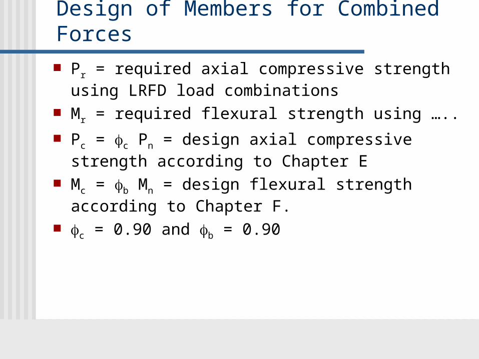
Pr = required axial compressive strength using LRFD load combinations
Mr = required flexural strength using …..
Pc = c Pn = design axial compressive strength according to Chapter E
Mc = b Mn = design flexural strength according to Chapter F.
c = 0.90 and b = 0.90

Design of Members for Combined Forces H1.2 Doubly and singly symmetric members in flexure
and tension Use the same equations indicated earlier But, Pr = required tensile strength
Pc = t Pn = design tensile strength according to Chapter D, Section D2.
t = 0.9
For doubly symmetric members, Cb in Chapter F may be increased by (1 + Pu/Pey) for axial tension
• Where, Pey = 2 EIy / Lb2

Design of Members for Combined Forces H1.3 Doubly symmetric members in single axis flexure
and compression For doubly symmetric members in flexure and
compression with moments primarily in one plane, it is permissible to consider two independent limit states separately, namely, (i) in-plane stability, and (ii) out-of-plane stability.
This is instead of the combined approach of Section H1.1 For the limit state of in-plane instability, Equations H1-1
shall be used with Pc, Mr, and Mc determined in the plane of bending.
For the limit state of out-of-plane buckling:
PrPco
M r
M cx
2
1.0
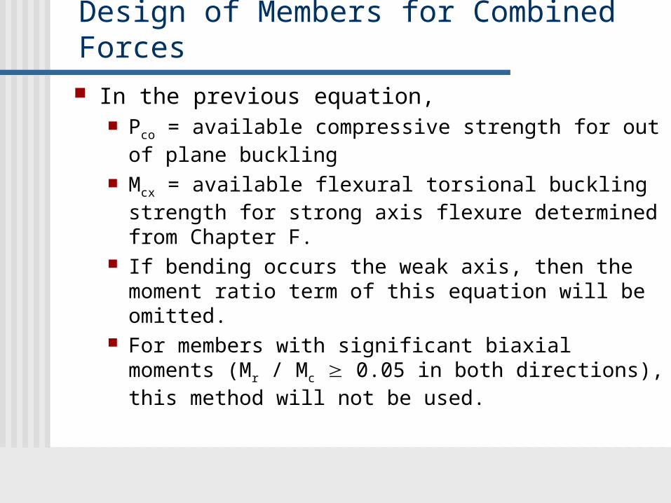
Design of Members for Combined Forces In the previous equation,
Pco = available compressive strength for out of plane buckling
Mcx = available flexural torsional buckling strength for strong axis flexure determined from Chapter F.
If bending occurs the weak axis, then the moment ratio term of this equation will be omitted.
For members with significant biaxial moments (Mr / Mc 0.05 in both directions), this method will not be used.

Design of Members for Combined Forces. The provisions of Section H1 apply to rolled wide-flange
shapes, channels, tee-shapes, round, square, and rectangular tubes, and many other possible combinations of doubly or singly symmetric sections built-up from plates.
cPY
bMp
Section P-M interactionFor zero-length beam-column
cPY

P-M interaction curve according to Section H1.1
cPn
bMn
P-M interactionfor full length
cPn
Column axial load capacityaccounting for x and y axis
buckling
Beam moment capacityaccounting for in-plane behavior
and lateral-torsional buckling
P-M interactionfor zero length
bMp
cPY

P-M interaction according to Section H1.3
cPnx
bMn
P-M interactionIn-plane, full length
cPnx
Column axial load capacityaccounting for x axis buckling
In-plane Beam moment capacityaccounting for flange local buckling
P-M interactionfor zero length
bMp
cPY
cPny
Out-of-plane Beam moment capacityaccounting for lateral-torsional buckling
P-M interactionOut-plane, full length
Column axial load capacityaccounting for y axis buckling

Design of Members Subject to Combined Loading
Steel Beam-Column Selection Tables Table 6-1 W shapes in Combined Axial and Bending
The values of p and bx for each rolled W section is provided in Table 6-1 for different unsupported lengths Kly and Lb.
The Table also includes the values of by, ty, and tr for all the rolled sections. These values are independent of length
p1
cPnkips 1
bx 8
9bM nxkip ft 1
by 8
9bM nykip ft 1
If pPr 0.2, then pPr bxM rx byM ry 1.0
If pPr 0.2, thenpPr2
9
8bxM rx byM ry 1.0

Table 6-1 is normally used with iteration to determine an appropriate shape.
After selecting a trial shape, the sum of the load ratios reveals if that trial shape is close, conservative, or unconservative with respect to 1.0.
When the trial shape is unconservative, and axial load effects dominate, the second trial shape should be one with a larger value of p.
Similarly, when the X-X or Y-Y axis flexural effects dominate, the second trial shape should one with a larger value of bx or by, respectively.
This process should be repeated until an acceptable shape is determined.

Estimating Required Forces - Analysis The beam-column interaction equation include both the
required axial forces and moments, and the available capacities.
The available capacities are based on column and beam strengths, and the P-M interaction equations try to account for their interactions.
However, the required Pr and Mr forces are determined from analysis of the structure. This poses a problem, because the analysis SHOULD account for second-order effects.
1st order analysis DOES NOT account for second-order effects.
What is 1st order analysis and what are second-order effects?
First-Order Analysis The most important assumption in 1st order analysis is
that FORCE EQUILIBRIUM is established in the UNDEFORMED state.
All the analysis techniques taught in CE270, CE371, and CE474 are first-order.
These analysis techniques assume that the deformation of the member has NO INFLUENCE on the internal forces (P, V, M etc.) calculated by the anlysis.
This is a significant assumption that DOES NOT work when the applied axial forces are HIGH.
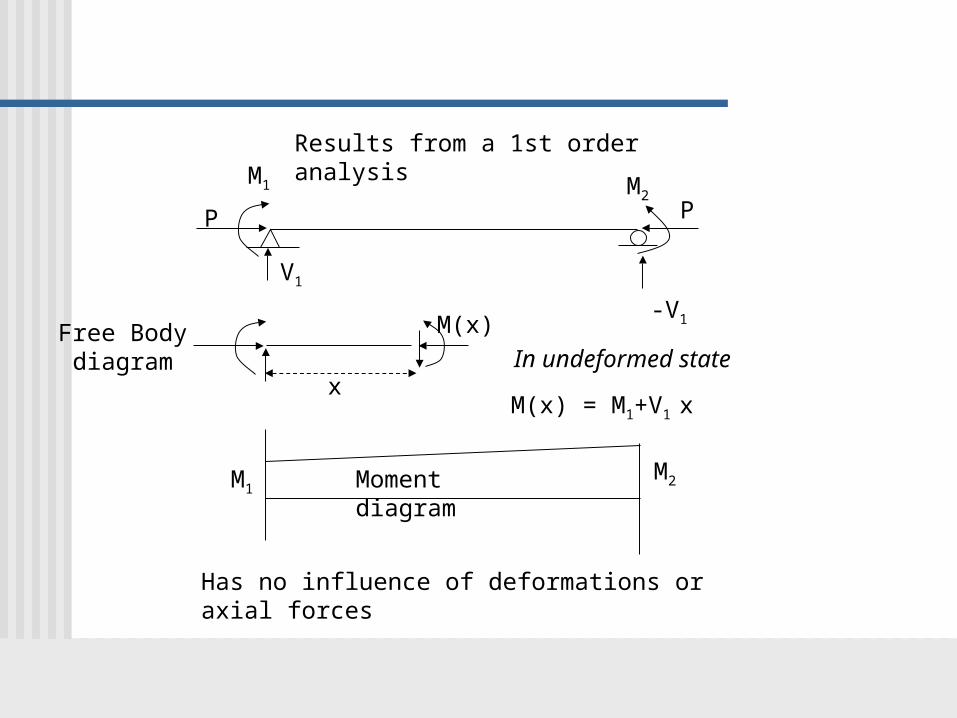
P P
M1 M2
Results from a 1st order analysis
V1
-V1
M1M2Moment diagram
M(x)
x
Free Bodydiagram In undeformed state
Has no influence of deformations or axial forces
M(x) = M1+V1 x

P P
M1 M2
2nd order effects
V1
-V1
M1M2Moment diagram
M(x)
x
Free Bodydiagram
In deformed state v(x) is the vertical deformation
Includes effects of deformations & axial forces
P M1
V1
M(x) = M1+V1 x + P v(x)

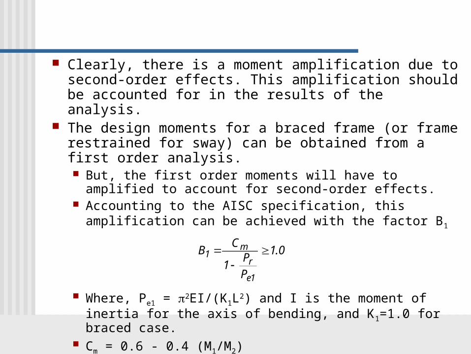
Clearly, there is a moment amplification due to second-order effects. This amplification should be accounted for in the results of the analysis.
The design moments for a braced frame (or frame restrained for sway) can be obtained from a first order analysis. But, the first order moments will have to amplified to
account for second-order effects. Accounting to the AISC specification, this amplification can
be achieved with the factor B1
Where, Pe1 = 2EI/(K1L2) and I is the moment of inertia for the axis of bending, and K1=1.0 for braced case.
Cm = 0.6 - 0.4 (M1/M2)
B1 Cm
1 PrPe1
1.0


Further Moment Amplification This second-order effect accounts for the deflection of
the beam in between the two supported ends (that do not translate). That is, the second-order effects due to the deflection from
the chord of the beam. When the frame is free to sway, then there are additional
second-order effects due to the deflection of the chord. The second-order effects associated with the sway of the
member () chord.

Mo
P
Mo
P
Mo
Mo
+
P
=
Mmax
As you can see, there is a moment amplification due to the sway of the beam chord by .
This is also referred as the story P- effect that produces second-order moments in sway frames due to interstory drift.
All the beam-columns in the story will have P- effect

The design moments for a sway frame (or unrestrained frame) can be obtained from a first order analysis. But, the first order moments will have to amplified to
account for second-order P- effects. According to the AISC specification, this amplification can
be achieved with the factor B2
Where, Pe2 = 2EI/(K2L2) and I is the moment of inertia for the axis of bending, and K2 is the effective length factor for the sway case.
This amplification is for all the beam-columns in the same story. It is a story amplification factor.
B2 1
1 PrPe2

The final understanding
The required forces (Pr, Vr, and Mr) can be obtained from a first-order analysis of the frame structure. But, they have to be amplified to account for second-order effects. For the braced frame, only the P- effects of deflection from
the chord will be present. For the sway frame, both the P- and the P- effects of
deflection from and of the chord will be present. These second-order effects can be accounted for by the
following approach. Step 1 - Develop a model of the building structure, where the
sway or interstory drift is restrained at each story. Achieve this by providing a horizontal reaction at each story
Step 2 - Apply all the factored loads (D, L, W, etc.) acting on the building structure to this restrained model.

Step 3 - Analyze the restrained structure.The resulting forces are referred as Pnt, Vnt, Mnt, where nt stands for no translation (restrained). The horizontal reactions at each story have to be stored
Step 4 - Go back to the original model, and remove the restraints at each story. Apply the horizontal reactions at each story with a negative sign as the new loading. DO NOT apply any of the factored loads.
Step 5 - Analyze the unrestrained structure. The resulting forces are referred as Plt, Vlt, and Mlt, where lt stands for lateral translation (free).
Step 6 - Calculate the required forces for design using
Pr = Pnt + B2 Plt
Vr = Vnt + B2 Vlt
Mr = B1 Mnt + B2 Mlt

Example