Resistance of through-plate component in beam-to-column ... · circular hollow columns ... A...
25
Resistance of through-plate component in beam-to-column joints with circular hollow columns Hoang Van-Long, Demonceau Jean-François, and Jaspart Jean-Pierre ArGEnCo Department, University of Liège, Belgium Abstract A configuration of beam-to-column joint with circular hollow section columns is proposed. A vertical plate, called through-plate, passing through the column is used to support the beams. In order to facilitate connecting the beams, two horizontal plates, each side of the column, are welded to the upper side of the through-plate. The lower flanges of the steel beams are connected to the horizontal plates by bolts, and the upper flanges are attached to the concrete slab by shear connections. The joint is considered as hinges in the construction phase while semi-rigid and partial strength can be adopted for the joint behaviour during the exploitation time. A development on the through-plate component of the joint is presented in this paper. Global behaviour of the joint under hogging moment and shear force is analysed leading to a mechanical model of the through-plate component. Using the elastic buckling theory of plates, the analytical formulas for critical stresses of the through-plate are obtained. The coefficients taking into account boundary conditions, material plasticity and geometrical imperfection are determined by finite element analysis. The proposed model is validated by experimental results showing a good accuracy. The design guideline for the component is finally provided for the practical purpose. Key words: beam-to-column joints; finite element analysis; experimental tests; component method 1. Introduction Within a European project entitled “ATTEL: Performance-based approaches for high-strength tubular columns and connections under earthquake and fire loadings” and funded by RFCS (Research Fund for Coal and Steel), one of the objectives is to provide building types where the use of high strength steel tubes for the columns can give the economic benefit [1]. In the case of static loading, a type of building has been proposed, from the global structural solution to the detail on the connections including the design guidelines.
Transcript of Resistance of through-plate component in beam-to-column ... · circular hollow columns ... A...
Resistance of through-plate component in beam-to-column joints with
circular hollow columns
Hoang Van-Long, Demonceau Jean-François, and Jaspart Jean-Pierre
ArGEnCo Department, University of Liège, Belgium
Abstract
A configuration of beam-to-column joint with circular hollow section columns is proposed. A vertical
plate, called through-plate, passing through the column is used to support the beams. In order to facilitate
connecting the beams, two horizontal plates, each side of the column, are welded to the upper side of the
through-plate. The lower flanges of the steel beams are connected to the horizontal plates by bolts, and the
upper flanges are attached to the concrete slab by shear connections. The joint is considered as hinges in the
construction phase while semi-rigid and partial strength can be adopted for the joint behaviour during the
exploitation time. A development on the through-plate component of the joint is presented in this paper. Global
behaviour of the joint under hogging moment and shear force is analysed leading to a mechanical model of the
through-plate component. Using the elastic buckling theory of plates, the analytical formulas for critical stresses
of the through-plate are obtained. The coefficients taking into account boundary conditions, material plasticity
and geometrical imperfection are determined by finite element analysis. The proposed model is validated by
experimental results showing a good accuracy. The design guideline for the component is finally provided for
the practical purpose.
Key words: beam-to-column joints; finite element analysis; experimental tests; component method
1. Introduction
Within a European project entitled “ATTEL: Performance-based approaches for high-strength tubular
columns and connections under earthquake and fire loadings” and funded by RFCS (Research Fund for Coal
and Steel), one of the objectives is to provide building types where the use of high strength steel tubes for the
columns can give the economic benefit [1]. In the case of static loading, a type of building has been proposed,
from the global structural solution to the detail on the connections including the design guidelines.
2
Concerning the global structural solution, a schematic view on the economic advantage of using high
strength steel (up to S700) in comparison with normal steel (S355) has been pointed out [2]. From the
conclusions of the research, one type of frames with the following characteristics is recommended to use high
strength steel for the columns: a large number of spans, the spans are large, and the number of storeys is small.
In the practice of constructions, it can see this building type in commercial centres, parkings, airports, etc. In
these frames, it can observe that the axial forces in the columns are preponderant in comparison with bending
moment, and the bending moments in the connections almost come from vertical loads.
With respect to base joints, simple column bases using rectangular end- plate with four anchor bolts has
been suggested, and the design guideline has been provide [3].
As far as the beam-to-column joints are concerned, the configuration shown on Fig.1 is proposed. In the
joint, one through-plate is welded to the column, on this plate two horizontal plates (each side of the column)
are attached by fillet welds. The lower flanges of the steel beams are connected to the horizontal plates by bolts
while the upper flanges are attached to the concrete slab by shear connections. The outside part of the through-
plate may be rectangular or triangular shapes. This joint can be considered as an economic solution, because a
modest volume of material is consumed, also the fabrication and construction procedures are quite simple
leading to the reduction of build-up time. On the structural behaviour aspect, the joints is considered as hinges
in the construction phrase while during the exploitation time the joint maybe becomes a semi-rigid and partial
strength connection due to the collaboration of the reinforced concrete slab. As in most practical cases, profiled
steel sheets are recommended to use in the composite slab, so that during the concrete casting time the lateral
stability of the steel beams can be assumed by these steel sheets.
Concerning the design rule for the beam-to-column joint, by using the component method concept, the joints
can be decomposed into the following components:
longitudinal slab reinforcement in tension;
bolts in shear (bolt shank in shear and associated plates in bearing);
welds in shear (through-plate to column and horizontal plates to through-plate welds);
3
through-plate and column in diagonal compression (combine of vertical and horizontal loads).
The detail calculation for the characterizations of the “longitudinal slab reinforcement in tension” component
can found the literature, e.g [4], while the “bolts in shear”, “plate in bearing” and “weld in shear” components
are coved by Eurocode-3, part 1-8 [5]. This paper presents a development on the “through-plate and column in
diagonal compression” component that is not available in the current codes and literatures. The failure mode of
the through-plate component is identified and then the mechanical models for the component is proposed
(Section 2). The proposed models is analytically formulated by using the linear elastic buckling theory of
plates; and the correction coefficients taking into account the nonlinear parameters are determined through
numerical studies (Section 3). Validation of the proposed model and formulas by experimental results are
presented in Section 4. The practical design guideline for the component, including calculation examples, is
drawn and presented in Section 5. Section 6 concerns the concluding remarks.
2. Assumptions and modelling
Let us examine the joint behaviour under a hogging moment and a shear force, as the situation during
the exploitation time. In order to highlight the behaviour of the through-plate, it supposes that the failure does
not occur in the bolts and the welds. As the friction between the concrete slab and the column can be negligible,
the vertical load at the connection is therefore completely transferred from the steel beam web to the through-
plate. On the other hand, the bending moment is equilibrium by two opposite horizontal forces, in tension on
the top and in compression on the bottom; the tension force is supported by the reinforcement rebars in the
concrete slab while the compression force is transferred to the through-plate. By consequence, a system
comprising the beam web, the lower beam flanges and the through-plate has a risk of buckling under the
diagonal compression (Fig.2). The reinforcement concrete slab and the steel column may be considered as the
boundaries assuming the stability of the mentioned system. The relative rotation between the lower flanges of
the beams and the horizontal plates may be negligible because they are attached one to other by the bolts. It can
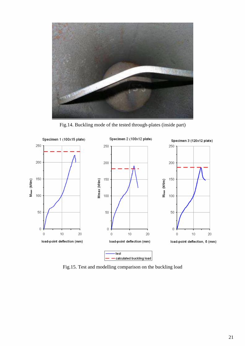
be imagined that the beam ends and the outside part of the through-plate are warped while the inside part of the
through-plate is laterally buckled (Figs. 2 and 3). The studies on the buckling of the whole system are quite
4
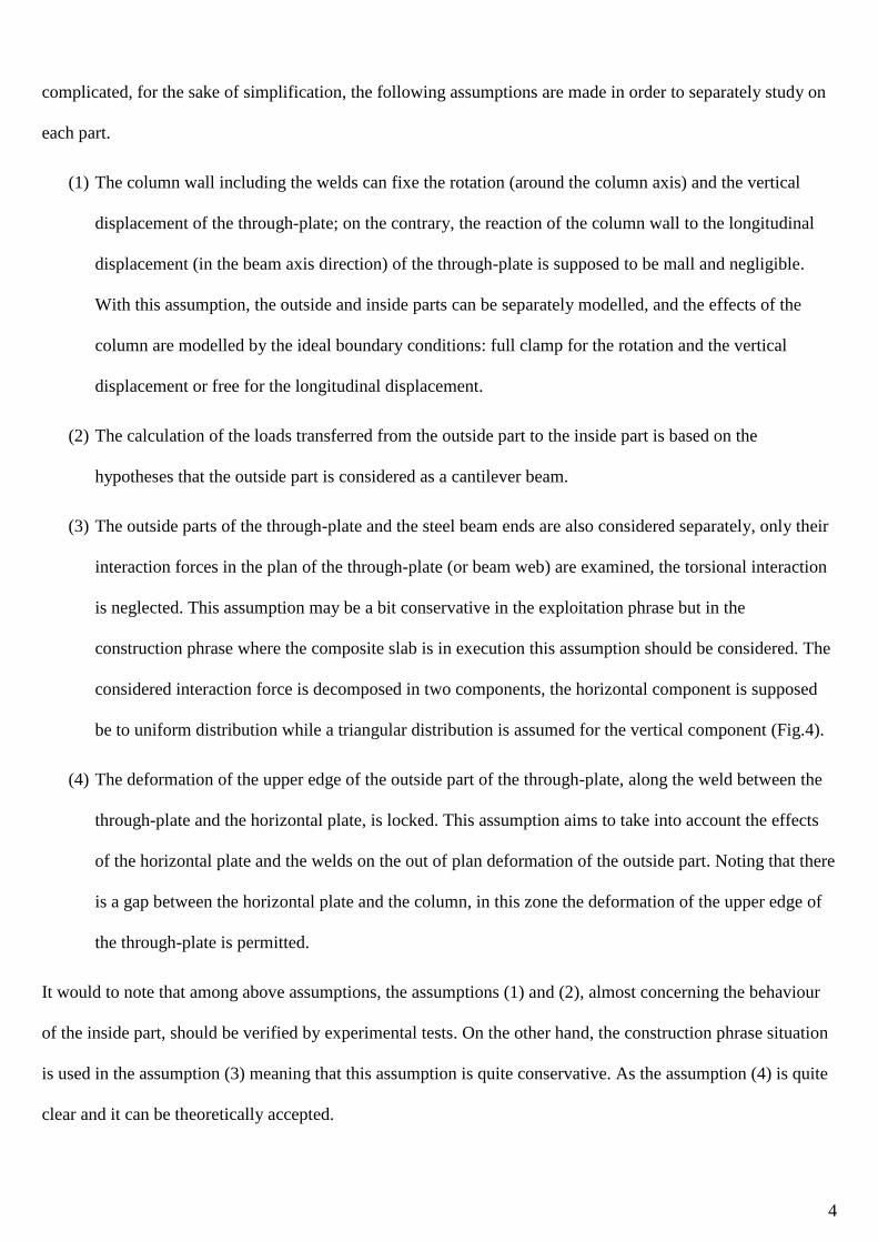
complicated, for the sake of simplification, the following assumptions are made in order to separately study on
each part.
(1) The column wall including the welds can fixe the rotation (around the column axis) and the vertical
displacement of the through-plate; on the contrary, the reaction of the column wall to the longitudinal
displacement (in the beam axis direction) of the through-plate is supposed to be mall and negligible.
With this assumption, the outside and inside parts can be separately modelled, and the effects of the
column are modelled by the ideal boundary conditions: full clamp for the rotation and the vertical
displacement or free for the longitudinal displacement.
(2) The calculation of the loads transferred from the outside part to the inside part is based on the
hypotheses that the outside part is considered as a cantilever beam.
(3) The outside parts of the through-plate and the steel beam ends are also considered separately, only their
interaction forces in the plan of the through-plate (or beam web) are examined, the torsional interaction
is neglected. This assumption may be a bit conservative in the exploitation phrase but in the
construction phrase where the composite slab is in execution this assumption should be considered. The
considered interaction force is decomposed in two components, the horizontal component is supposed
be to uniform distribution while a triangular distribution is assumed for the vertical component (Fig.4).
(4) The deformation of the upper edge of the outside part of the through-plate, along the weld between the
through-plate and the horizontal plate, is locked. This assumption aims to take into account the effects
of the horizontal plate and the welds on the out of plan deformation of the outside part. Noting that there
is a gap between the horizontal plate and the column, in this zone the deformation of the upper edge of
the through-plate is permitted.
It would to note that among above assumptions, the assumptions (1) and (2), almost concerning the behaviour
of the inside part, should be verified by experimental tests. On the other hand, the construction phrase situation
is used in the assumption (3) meaning that this assumption is quite conservative. As the assumption (4) is quite
clear and it can be theoretically accepted.
5
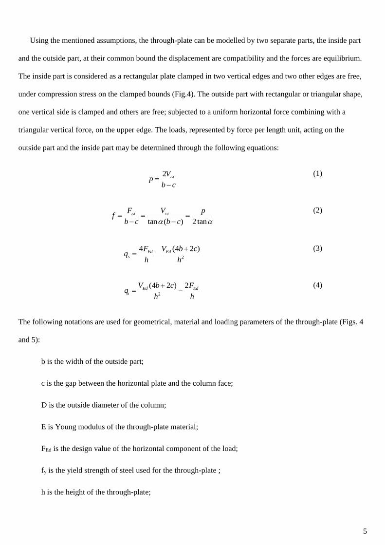
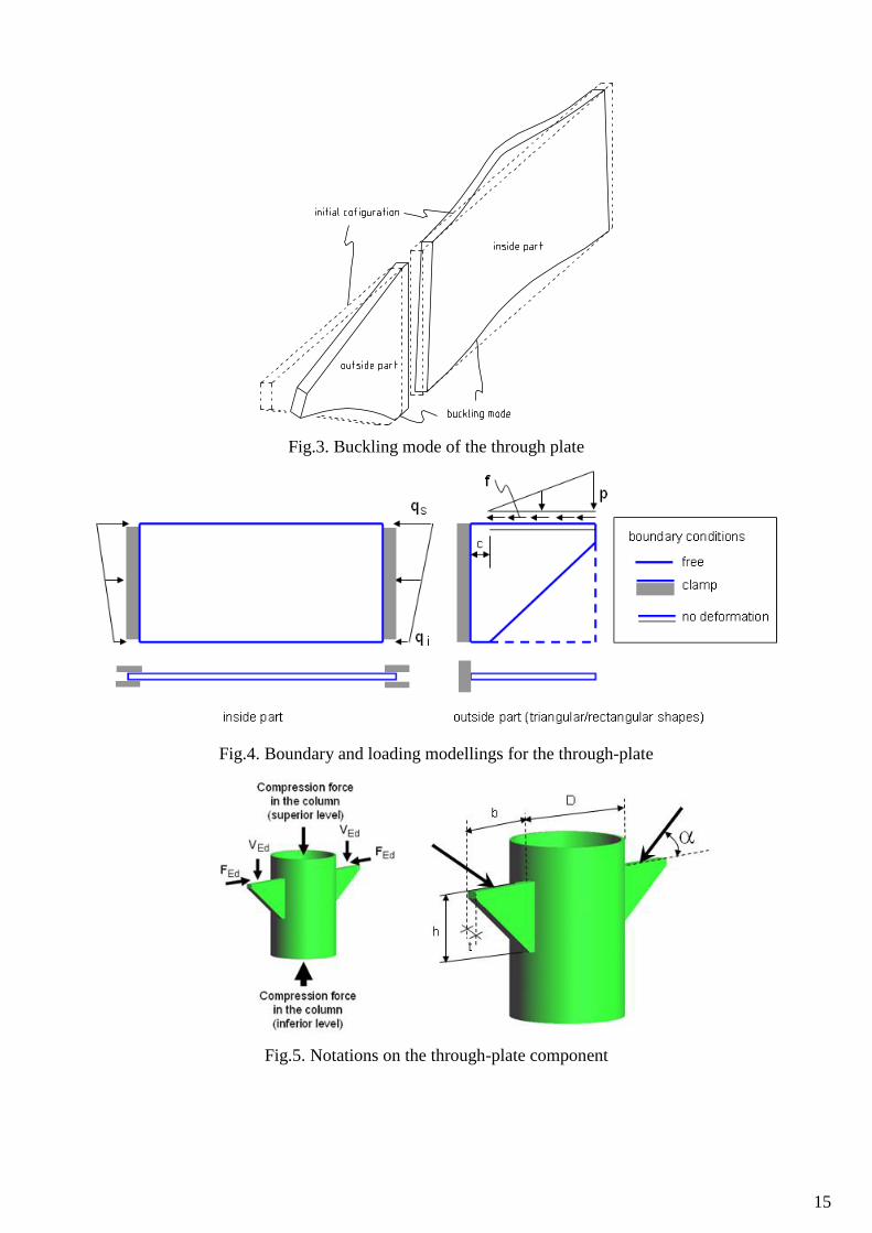
Using the mentioned assumptions, the through-plate can be modelled by two separate parts, the inside part
and the outside part, at their common bound the displacement are compatibility and the forces are equilibrium.
The inside part is considered as a rectangular plate clamped in two vertical edges and two other edges are free,
under compression stress on the clamped bounds (Fig.4). The outside part with rectangular or triangular shape,
one vertical side is clamped and others are free; subjected to a uniform horizontal force combining with a
triangular vertical force, on the upper edge. The loads, represented by force per length unit, acting on the
outside part and the inside part may be determined through the following equations:
2Ed
Vp
b c
(1)
tan ( ) 2 tan
Ed EdF V p
fb c b c
(2)
2
4 (4 2 )Ed Eds
F V b cq
h h
(3)
2
(4 2 ) 2Ed Edi
V b c Fq
h h
(4)
The following notations are used for geometrical, material and loading parameters of the through-plate (Figs. 4
and 5):
b is the width of the outside part;
c is the gap between the horizontal plate and the column face;
D is the outside diameter of the column;
E is Young modulus of the through-plate material;
FEd is the design value of the horizontal component of the load;
fy is the yield strength of steel used for the through-plate ;
h is the height of the through-plate;
6
t is the thickness of the through-plate;
VEd is the design value of the vertical component of the load;
is the load direction;
is Poisson ratio of the through-plate material.
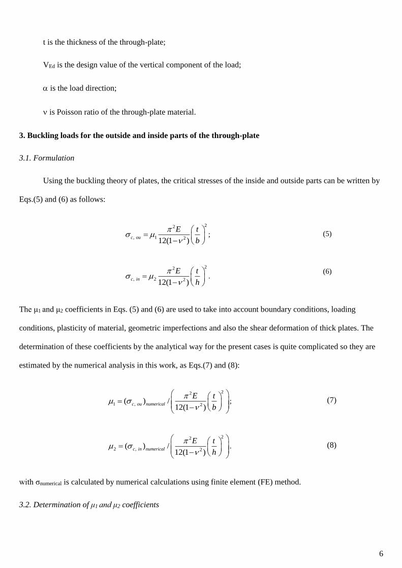
3. Buckling loads for the outside and inside parts of the through-plate
3.1. Formulation
Using the buckling theory of plates, the critical stresses of the inside and outside parts can be written by
Eqs.(5) and (6) as follows:
22
, 1 212(1 )c ou
E t
b
; (5)
22
, 2 212(1 )c in
E t
h
.
(6)
The μ1 and μ2 coefficients in Eqs. (5) and (6) are used to take into account boundary conditions, loading
conditions, plasticity of material, geometric imperfections and also the shear deformation of thick plates. The
determination of these coefficients by the analytical way for the present cases is quite complicated so they are
estimated by the numerical analysis in this work, as Eqs.(7) and (8):
22
1 , 2( ) /
12(1 )c ou numerical
E t
b
; (7)
22
2 , 2( ) /
12(1 )c in numerical
E t
h
. (8)
with σnumerical is calculated by numerical calculations using finite element (FE) method.
3.2. Determination of μ1 and μ2 coefficients
7
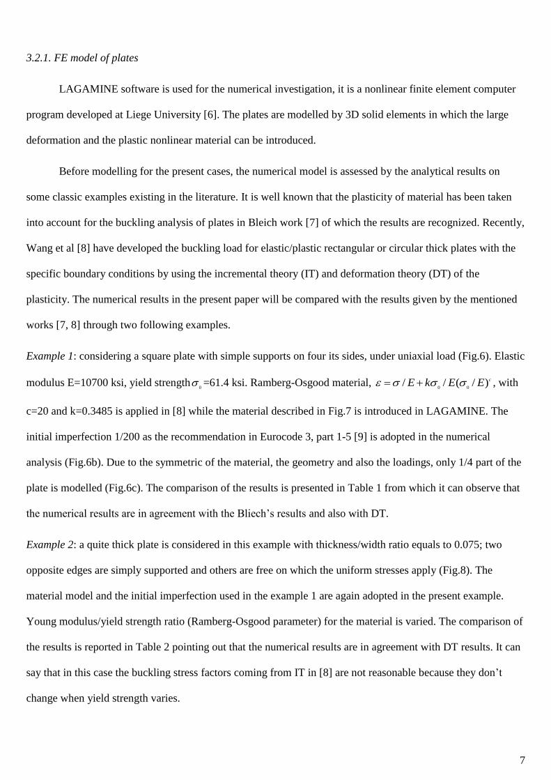
3.2.1. FE model of plates
LAGAMINE software is used for the numerical investigation, it is a nonlinear finite element computer
program developed at Liege University [6]. The plates are modelled by 3D solid elements in which the large
deformation and the plastic nonlinear material can be introduced.
Before modelling for the present cases, the numerical model is assessed by the analytical results on
some classic examples existing in the literature. It is well known that the plasticity of material has been taken
into account for the buckling analysis of plates in Bleich work [7] of which the results are recognized. Recently,
Wang et al [8] have developed the buckling load for elastic/plastic rectangular or circular thick plates with the
specific boundary conditions by using the incremental theory (IT) and deformation theory (DT) of the
plasticity. The numerical results in the present paper will be compared with the results given by the mentioned
works [7, 8] through two following examples.
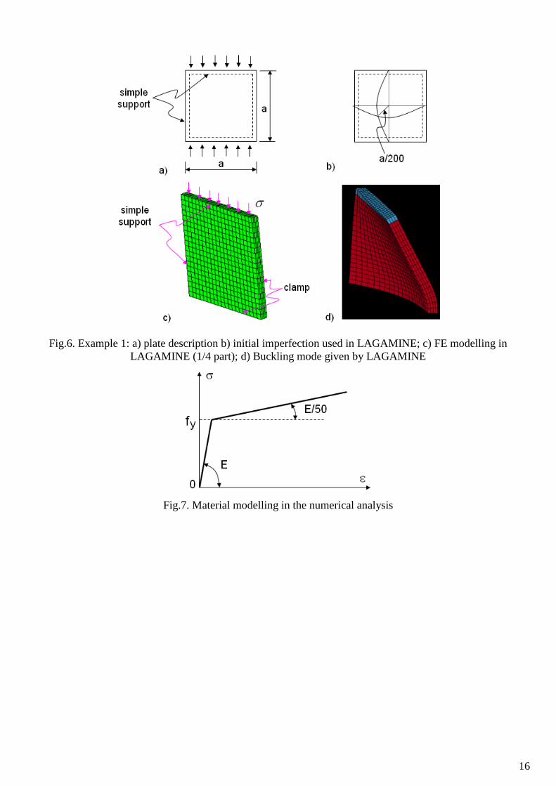
Example 1: considering a square plate with simple supports on four its sides, under uniaxial load (Fig.6). Elastic
modulus E=10700 ksi, yield strength0
=61.4 ksi. Ramberg-Osgood material, 0 0
/ / ( / )cE k E E , with
c=20 and k=0.3485 is applied in [8] while the material described in Fig.7 is introduced in LAGAMINE. The
initial imperfection 1/200 as the recommendation in Eurocode 3, part 1-5 [9] is adopted in the numerical
analysis (Fig.6b). Due to the symmetric of the material, the geometry and also the loadings, only 1/4 part of the
plate is modelled (Fig.6c). The comparison of the results is presented in Table 1 from which it can observe that
the numerical results are in agreement with the Bliech’s results and also with DT.
Example 2: a quite thick plate is considered in this example with thickness/width ratio equals to 0.075; two
opposite edges are simply supported and others are free on which the uniform stresses apply (Fig.8). The
material model and the initial imperfection used in the example 1 are again adopted in the present example.
Young modulus/yield strength ratio (Ramberg-Osgood parameter) for the material is varied. The comparison of
the results is reported in Table 2 pointing out that the numerical results are in agreement with DT results. It can
say that in this case the buckling stress factors coming from IT in [8] are not reasonable because they don’t
change when yield strength varies.
8
From the examples, it can say that the above numerical model, as meshing, element type, material
modelling, initial imperfection modelling, and boundary condition modelling can be used to determine the
buckling loads of plates.
3.2.2. Determination of μ1 and μ2 coefficients
The mechanical models for the outside and inside parts of the through plate (Fig.4) are introduced in the
FE on which the meshing, the element type, and the material modelling are already presented in Section 3.2.1.
With respect to the geometric imperfection modelling, the value of 1/200 of the span is again used with the
forms shown on Fig.9. As S355 steel is the most popular steel grade in markets, this steel characteristics are
introduced in the FE models. In order to cover almost practical possibilities, the following parameters are varied
(see Fig.5 for the notices):
- the load direction for the outside part, vary from 150 to 900;
- the thickness/width ratio of the outside part, t/b vary from 0.05 to 0.15;
- the height/width ratio of the outside part, h/b vary from 0.6 to 1.4;
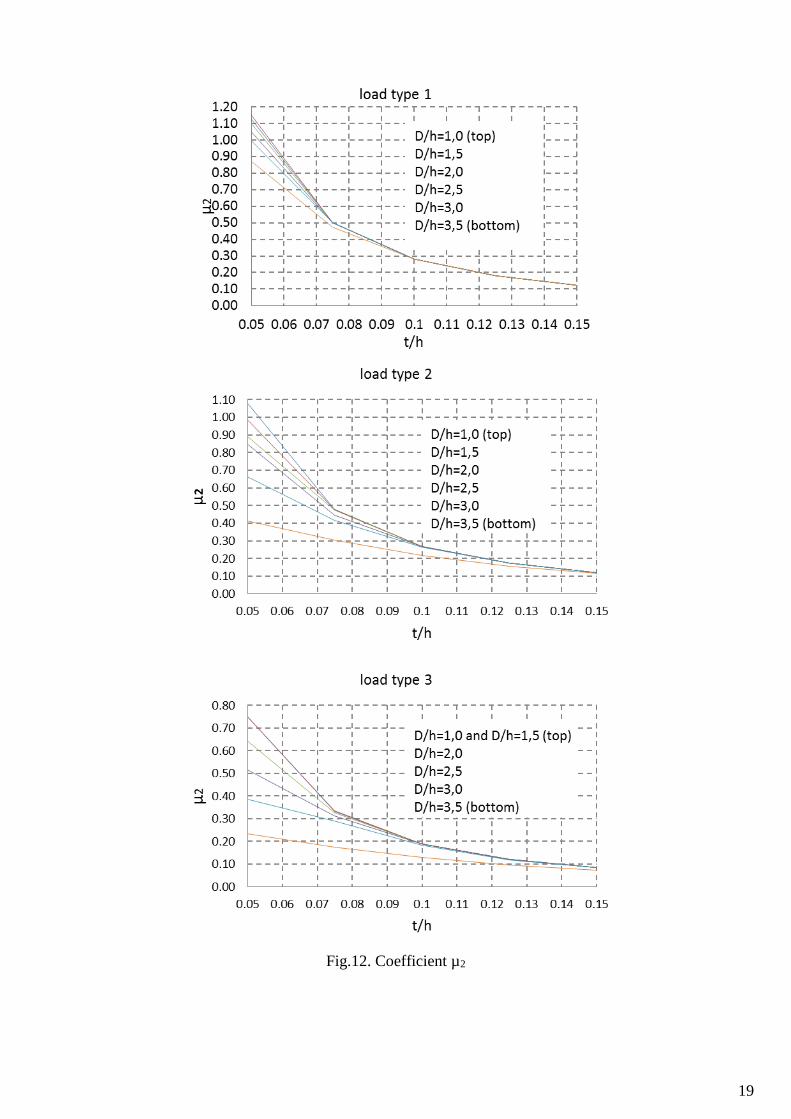
- three distribution types the load type for the inside part: bi-triangular, triangular and uniform (Fig.10);
- the thickness/high ratio of the inside part, t/h vary from 0.05 to 0.15;
- the width/high ratio of the inside part, D/h vary from 0.6 to 1.4;
- the value c of the gap between the horizontal plate and the column (Fig.4) equals to 0.1b.
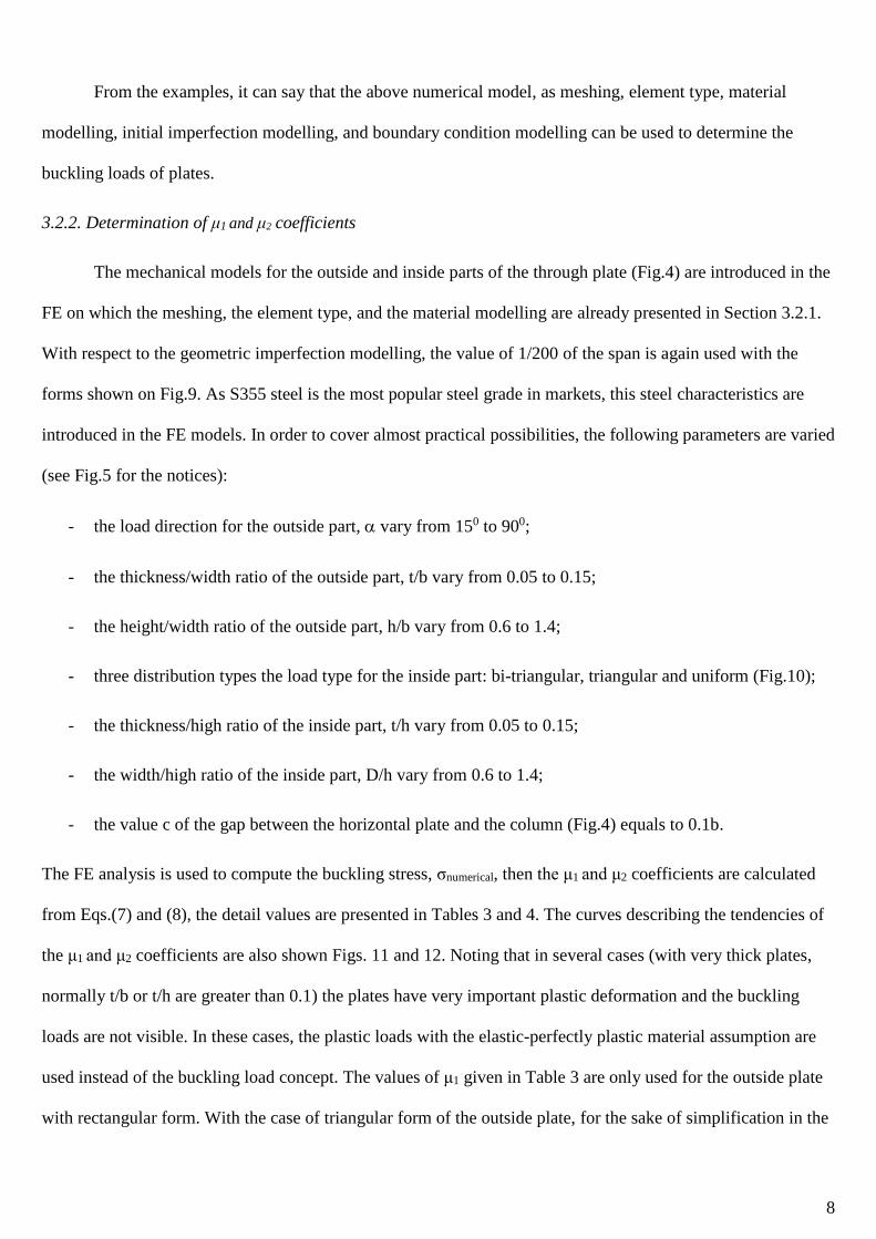
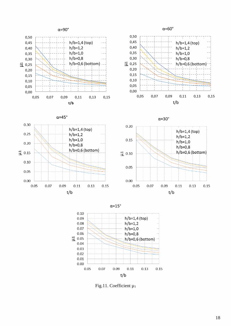
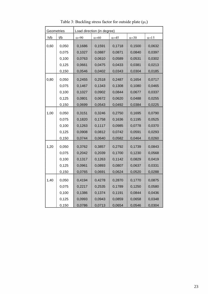
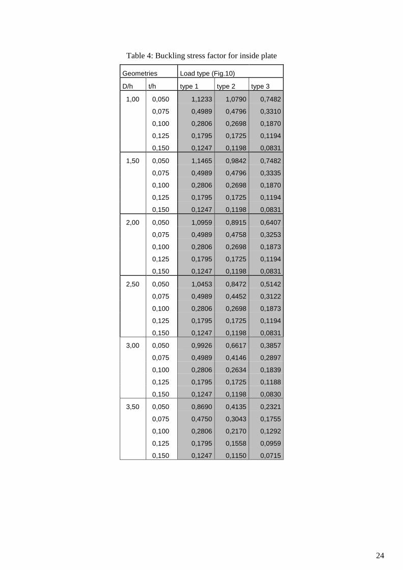
The FE analysis is used to compute the buckling stress, σnumerical, then the μ1 and μ2 coefficients are calculated
from Eqs.(7) and (8), the detail values are presented in Tables 3 and 4. The curves describing the tendencies of
the μ1 and μ2 coefficients are also shown Figs. 11 and 12. Noting that in several cases (with very thick plates,
normally t/b or t/h are greater than 0.1) the plates have very important plastic deformation and the buckling
loads are not visible. In these cases, the plastic loads with the elastic-perfectly plastic material assumption are
used instead of the buckling load concept. The values of μ1 given in Table 3 are only used for the outside plate
with rectangular form. With the case of triangular form of the outside plate, for the sake of simplification in the
9
practices, 0,9μ1 can be approximated, this value is observed from the numerical analysis results. In the
calculation of μ1 and μ2 given in Tables 3 and 4, the buckling stresses (σnumerical in Eqs.(7) and (8)) are defined
as the following:
2buckling
p
t for the outside part,
(9)
max( , )s i
buckling
q q
t for the inside part.
(10)
p, qs and qi in Eqs.(9) and (10) are the values at the critical states of the plates in the FE analysis, the relation of
these quantities with the applied loads, VEd and FEd, are described by Eqs.(1), (2) and (3).
4. Model validation for the inside part of the through-plate
This section presents the validation of the proposed model for the through-plate by using the
experimental results. The main objective is the validation of the assumptions (1) and (2) (as mentioned in
Section 2) and the FE model presented in Section 3. Therefore, the proposed models of the plate (Fig.4), the
actual material and geometries of the through-plates are introduced in the FE analysis for obtaining the critical
loads that are used to compare with experimental data.
4.1. Experimental tests
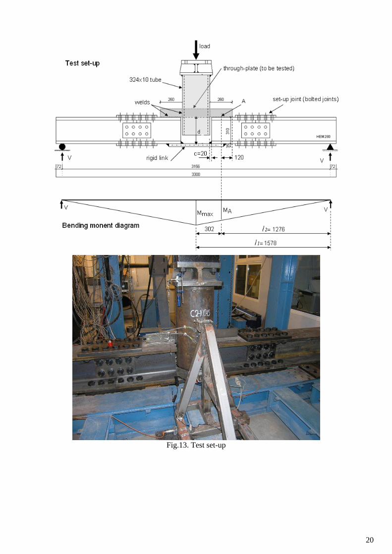
Three tests on the inside part of the through-plate were performed at Thessaly University within ATTEL
project, the test set-up is outlined on Fig. 13, and the detail on the tests can be found in [10]. As the aim is
oriented to study the inside part of the through-plate component, the concrete slab is replaced by a rigid link
that almost supports only the tension force. Also, as the bolts are not the objectives then the steel beams are
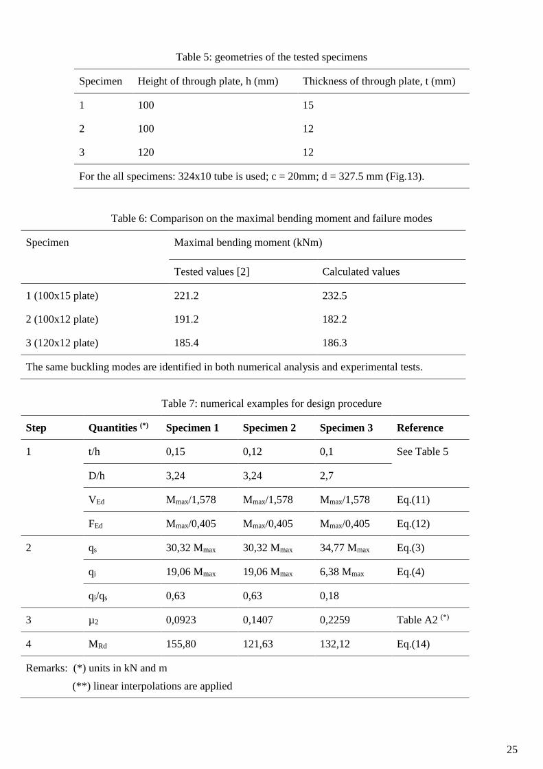
directly welded to the through plate. The main geometries of the three specimens are reported on Table 5. The
mean values of the yield strength and the ultimate strength of the through plates given by coupon tests are 418
N/mm2 and 602 N/mm2, respectively. Among the results given by the tests, the maximal bending moments
(Mmax on Fig.13) and the failure modes (Fig.14) are used to validate the proposed formulas.
4.2. Calculation of the resistance of the tested through- plate
10
As the maximal bending moment (Mmax) is used to compare, the applied loads on the through-plate need to
be written under the function of Mmax.
The vertical load (VEd) equals to the reaction of the supports (Fig.13):
max 1/
EdV M l . (11)
As the bending moment at the middle point of the weld lines between the through-plate and the beam
flange (point A on Fig.13) is used to calculated the horizontal load, FEd, this force can be written under
the function of the maximal moment by:
max 2 1/ ( / ) /
Ed AF M d M l l d . (12)
Substituting VEd and FEd in Eqs.(11) and (12) into Eqs.(3) and (4) one obtains 0.625i sq q for specimens 1
and 2; and 0.183i sq q for specimen 3. These load distributions are introduced in the FE model with the
boundary conditions and initial imperfection shown on Figs.4 and 9, respectively. Concerning the material
modelling, the actual curve with the measured values of the yield strength and the ultimate strength are used.
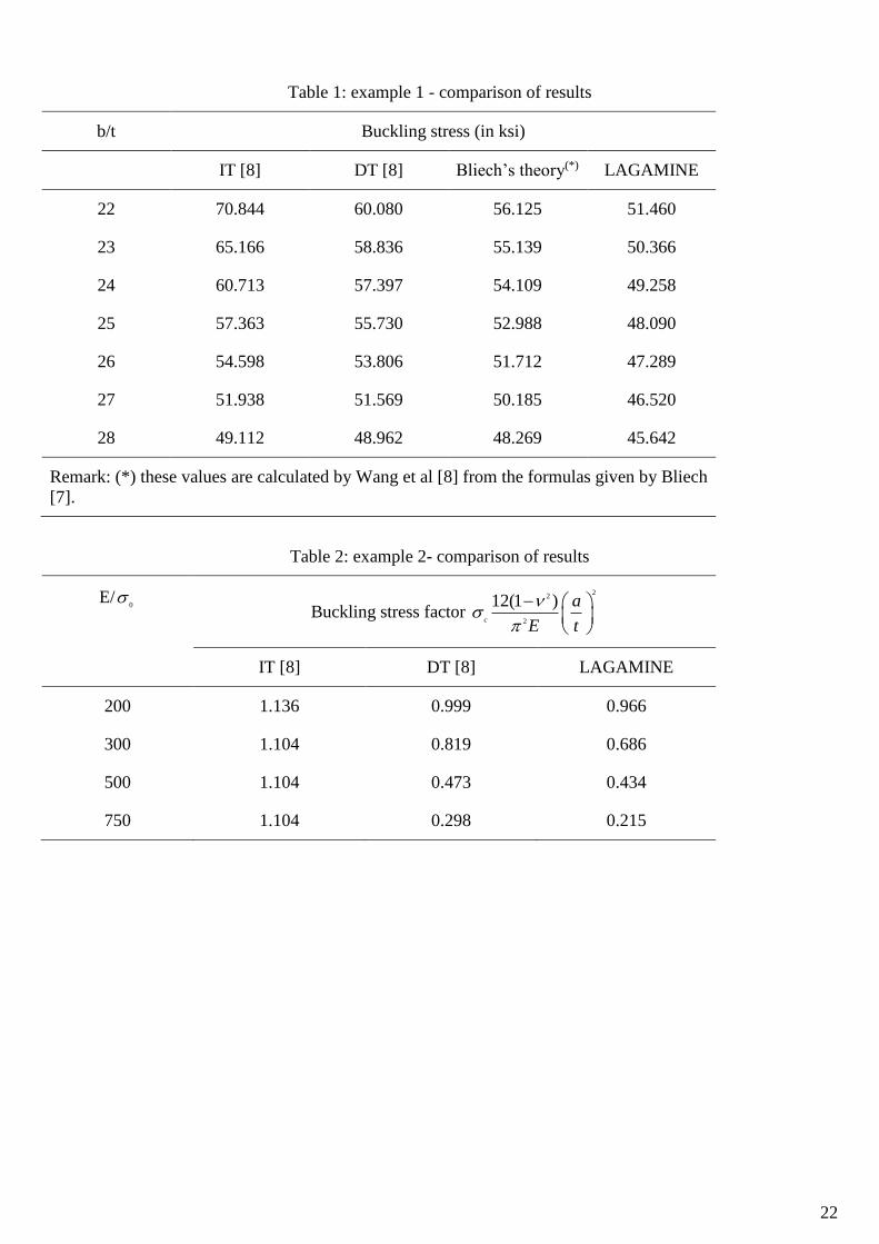
4.3. Comparison and discussions
The calculated and tested values of the maximal bending moments are compared, as summarized in
Table 6 and on Fig.15. The comparisons on the complete curves are not dealt with because the experimental
curves including the deformation of the test set-up system (steel beam, set-up joints, etc.) that did not introduce
in the calculated curves. From the comparison with the experimental results, it can be say that the accuracy of
the proposed model on the resistance of the through-plate can respond the practical purpose.
As the examples, the resistance of the tested specimens will be also calculated by using the proposed
design procedure in Section 5.
5. Design procedure
The design procedure for verifying the resistance of the through-plate components can be now
summarized as follow.
11
Step 1: determining the applied loads on the connection, VEd and FEd. VEd equals to the design value of
the shear force at the beam end while FEd equals to the ratio of the design bending moment at the
connection to the height of the joint, the last is the distance between the gravity centre of the rebars to
the upper side of the through plate.
Step 2: calculating the load direction for the outside part, arctan Ed
Ed
V
F ; and the load parameters, qs
and qi, for the inside part by using Eqs.(3) and (4).
Step 3: with the load and dimension parameters, computing the coefficients 1 and 2 from Tables 3 and
4 in which the linear interpolation can be applied for the intermediate points.
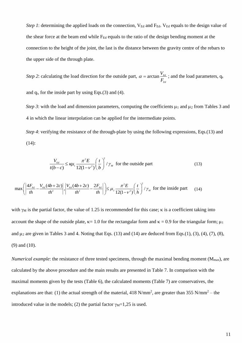
Step 4: verifying the resistance of the through-plate by using the following expressions, Eqs.(13) and
(14):
22
1 2/
( ) 12(1 )
Ed
M
V E t
t b c b
for the outside part (13)
22
22 2 2
4 (4 2 ) (4 2 ) 2max , /
12(1 )
Ed Ed Ed Ed
M
F V b c V b c F E t
th th th th h
for the inside part (14)
with M is the partial factor, the value of 1.25 is recommended for this case; is a coefficient taking into
account the shape of the outside plate, = 1.0 for the rectangular form and = 0.9 for the triangular form; 1
and 2 are given in Tables 3 and 4. Noting that Eqs. (13) and (14) are deduced from Eqs.(1), (3), (4), (7), (8),
(9) and (10).
Numerical example: the resistance of three tested specimens, through the maximal bending moment (Mmax), are
calculated by the above procedure and the main results are presented in Table 7. In comparison with the
maximal moments given by the tests (Table 6), the calculated moments (Table 7) are conservatives, the
explanations are that: (1) the actual strength of the material, 418 N/mm2, are greater than 355 N/mm2 – the
introduced value in the models; (2) the partial factor M=1,25 is used.
12
Remarks: the above development is devoted to two-side joints, in the case of one-side joints (i.e. in the
external columns) the proposed joint configuration, but without one outside part, can be used. The
formulas concerning the outside part are still suitable for this case while a quite large conservative is
observed for using the formulas related to the inside part. However, in order to avoid the important
transverse shear in the column and also the local bending in the column wall, the hinge model is
recommended for the one-side joints in the proposed building frame-type; the slab reinforcement detail
should be accordingly adopted.
6. Conclusions
A configuration for beam-to-column joint with steel hollow section column is proposed in this paper.
This type of beam-to-column joint is recommended for using in buildings subjected to static loading with the
vertical load being preponderant in comparison with horizontal load. The economic benefit of using high
strength steel tubes for the columns is identified in this kind of buildings [2]. The main component of the joint
is a through-plate passing through the column and supporting the steel beams. The calculation procedure for the
resistance of the through-plate component is developed. The development is based on the linear elastic buckling
theory of thin plates while the plasticity of the material, the geometrical imperfection, and the shear effect of
thick plates are taken into account by numerical way. The design procedure for the investigated component is
proposed, from which in knowing the applied loads, the geometries and the materials, the resistance of the
component can be directly determined. The results given by the proposed design model are validated by
experimental data showing that the accuracy responds to the practical purpose.
Acknowledgements
This work was carried out with a financial grant from the Research Fund for Coal and Steel of the
European Community, within ATTEL project: “Performance-Based Approaches for High Strength Steel
Tubular Columns and Connections under Earthquake and Fire Loadings”, Grant N0 RFSR-CT-2008-00037.

13
References
[1] ATTEL project: “Performance-based approaches for high-strength tubular columns and connections under
earthquake and fire loadings”, Final Report, 2012, http://orbi.ulg.ac.be/handle/2268/126526
[2] Hoang V.L., Demonceau J.F, Ly D.P.L, Rossi B. Field of application of high strength steel circular tubes for
steel and composite columns from an economic point of view. Journal of Constructional Steel Research, 2011
(67):1001-1021.
[3] Hoang V.L., Demonceau J.F., Jaspart J.P. Proposal of a simplified analytical approach for the
characterisation of the end-plate component in circular tube connection. Journal of Constructional Steel
Research, 2013 (90): 245-252.
[4] Anderson D (ed). COST C1 - Composite steel-concrete joints in frames for buildings: Design provisions.
Brussels – Luxembourg 1999.
[5] Eurocode 3: Design of steel structures - Part 1-8: Design of joints. EN 1993-1-8, Brussels, 2003.
[6] LAGAMINE: User’s manual, University of Liege, 2010.
[7] Bliech F. Buckling Strength of metal structures. McGraw-Hill, New York, 1952.
[8] Wang C.M., Xiang Y., Chacrabarty J. Elastic/plastic buckling of thick plates. Intenational journal of Solids
and Structures, 2001 (38): 8617-8640.
[9] Eurocode 3: Design of steel structures - Part 1-5: Plated structural elements. EN 1993-1-5, Brussels, 2003.
[10] ATTEL project: “Performance-based approaches for high-strength tubular columns and connections under
earthquake and fire loadings”, Deliverable Report D.3: simulation data relevant to the selected typologies of
base joints, of HSS-CHS columns and HSS-CFT column and of HSS-concrete composite beam-to-column
joints, 2012, http://orbi.ulg.ac.be/handle/2268/126857

14
Fig.1. Proposed beam-to-column joint configuration
Fig.2. Considered buckling mode for the joint
15
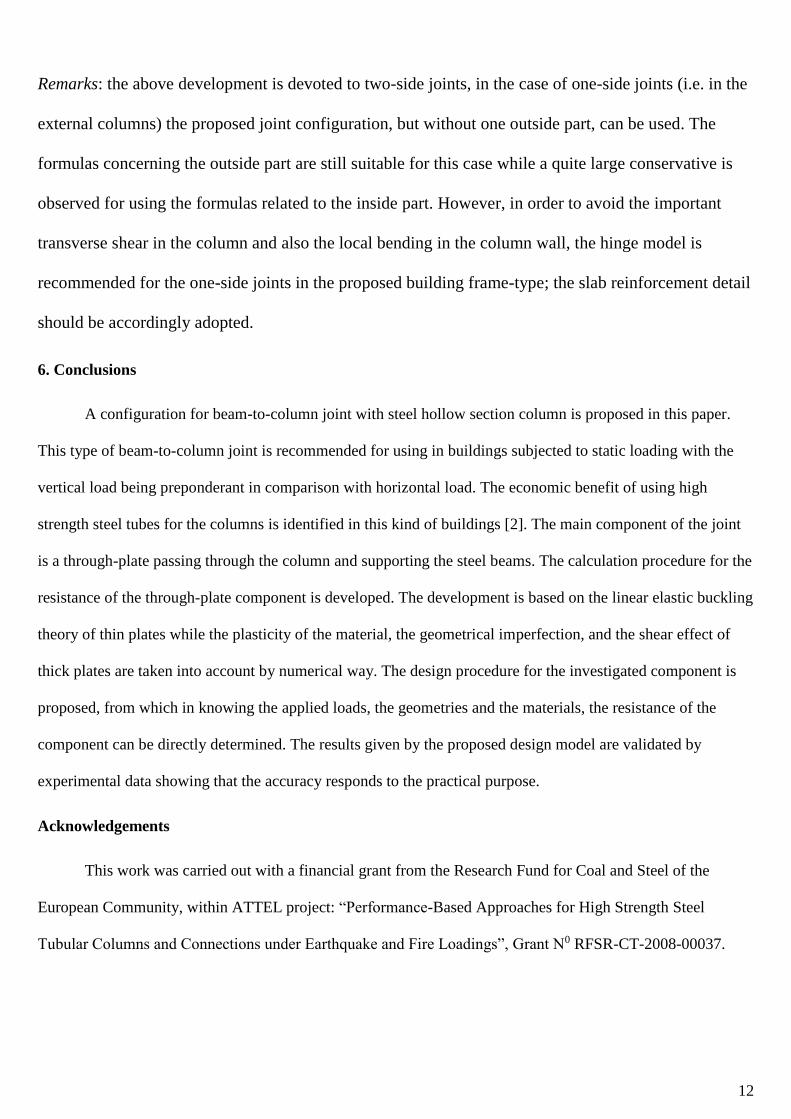
Fig.3. Buckling mode of the through plate
Fig.4. Boundary and loading modellings for the through-plate
Fig.5. Notations on the through-plate component
16
Fig.6. Example 1: a) plate description b) initial imperfection used in LAGAMINE; c) FE modelling in
LAGAMINE (1/4 part); d) Buckling mode given by LAGAMINE
Fig.7. Material modelling in the numerical analysis

17
Fig.8. Example 2: a) plate description b) initial imperfection used in LAGAMINE; c) FE modelling in
LAGAMINE; d) Buckling mode given by LAGAMINE
Fig.9. Modelling of the geometric imperfection for the plates
Fig.10. Loading types for the inside plate
18
0,00
0,05
0,10
0,15
0,20
0,25
0,30
0,35
0,40
0,45
0,50
0,05 0,07 0,09 0,11 0,13 0,15
µ1
t/b
α=90°
h/b=1,4 (top)h/b=1,2h/b=1,0h/b=0,8h/b=0,6 (bottom)
0,00
0,05
0,10
0,15
0,20
0,25
0,30
0,35
0,40
0,45
0,50
0,05 0,07 0,09 0,11 0,13 0,15
µ1
t/b
α=60°
h/b=1,4 (top)h/b=1,2h/b=1,0h/b=0,8h/b=0,6 (bottom)
Fig.11. Coefficient µ1
19
Fig.12. Coefficient µ2
20
Fig.13. Test set-up
21
Fig.14. Buckling mode of the tested through-plates (inside part)
Fig.15. Test and modelling comparison on the buckling load
22
Table 1: example 1 - comparison of results
b/t Buckling stress (in ksi)
IT [8] DT [8] Bliech’s theory(*) LAGAMINE
22 70.844 60.080 56.125 51.460
23 65.166 58.836 55.139 50.366
24 60.713 57.397 54.109 49.258
25 57.363 55.730 52.988 48.090
26 54.598 53.806 51.712 47.289
27 51.938 51.569 50.185 46.520
28 49.112 48.962 48.269 45.642
Remark: (*) these values are calculated by Wang et al [8] from the formulas given by Bliech
[7].
Table 2: example 2- comparison of results
E/0
Buckling stress factor
22
2
12(1 )c
a
E t
IT [8] DT [8] LAGAMINE
200 1.136 0.999 0.966
300 1.104 0.819 0.686
500 1.104 0.473 0.434
750 1.104 0.298 0.215
23
Table 3: Buckling stress factor for outside plate (μ1)
Geometries Load direction (in degree)
h/b t/b
0,60 0,050 0,1686 0,1591 0,1718 0,1500 0,0632
0,075 0,1027 0,0887 0,0871 0,0840 0,0397
0,100 0,0763 0,0610 0,0589 0,0531 0,0302
0,125 0,0661 0,0475 0,0433 0,0381 0,0213
0,150 0,0546 0,0402 0,0343 0,0304 0,0185
0,80 0,050 0,2455 0,2518 0,2487 0,1654 0,0717
0,075 0,1467 0,1343 0,1308 0,1080 0,0465
0,100 0,1027 0,0902 0,0844 0,0677 0,0337
0,125 0,0801 0,0672 0,0620 0,0488 0,0255
0,150 0,0699 0,0543 0,0492 0,0384 0,0225
1,00 0,050 0,3151 0,3246 0,2750 0,1695 0,0790
0,075 0,1820 0,1758 0,1636 0,1195 0,0525
0,100 0,1263 0,1117 0,0985 0,0778 0,0370
0,125 0,0908 0,0812 0,0742 0,0591 0,0293
0,150 0,0744 0,0640 0,0582 0,0464 0,0260
1,20 0,050 0,3762 0,3857 0,2792 0,1739 0,0843
0,075 0,2042 0,2039 0,1700 0,1230 0,0568
0,100 0,1317 0,1263 0,1142 0,0829 0,0419
0,125 0,0961 0,0893 0,0807 0,0637 0,0331
0,150 0,0765 0,0691 0,0624 0,0520 0,0288
1,40 0,050 0,4194 0,4278 0,2870 0,1770 0,0875
0,075 0,2217 0,2535 0,1789 0,1250 0,0580
0,100 0,1386 0,1374 0,1191 0,0844 0,0436
0,125 0,0993 0,0943 0,0859 0,0658 0,0348
0,150 0,0786 0,0713 0,0654 0,0546 0,0304
24
Table 4: Buckling stress factor for inside plate
Geometries Load type (Fig.10)
D/h t/h type 1 type 2 type 3
1,00 0,050 1,1233 1,0790 0,7482
0,075 0,4989 0,4796 0,3310
0,100 0,2806 0,2698 0,1870
0,125 0,1795 0,1725 0,1194
0,150 0,1247 0,1198 0,0831
1,50 0,050 1,1465 0,9842 0,7482
0,075 0,4989 0,4796 0,3335
0,100 0,2806 0,2698 0,1870
0,125 0,1795 0,1725 0,1194
0,150 0,1247 0,1198 0,0831
2,00 0,050 1,0959 0,8915 0,6407
0,075 0,4989 0,4758 0,3253
0,100 0,2806 0,2698 0,1873
0,125 0,1795 0,1725 0,1194
0,150 0,1247 0,1198 0,0831
2,50 0,050 1,0453 0,8472 0,5142
0,075 0,4989 0,4452 0,3122
0,100 0,2806 0,2698 0,1873
0,125 0,1795 0,1725 0,1194
0,150 0,1247 0,1198 0,0831
3,00 0,050 0,9926 0,6617 0,3857
0,075 0,4989 0,4146 0,2897
0,100 0,2806 0,2634 0,1839
0,125 0,1795 0,1725 0,1188
0,150 0,1247 0,1198 0,0830
3,50 0,050 0,8690 0,4135 0,2321
0,075 0,4750 0,3043 0,1755
0,100 0,2806 0,2170 0,1292
0,125 0,1795 0,1558 0,0959
0,150 0,1247 0,1150 0,0715
25
Table 5: geometries of the tested specimens
Specimen Height of through plate, h (mm) Thickness of through plate, t (mm)
1 100 15
2 100 12
3 120 12
For the all specimens: 324x10 tube is used; c = 20mm; d = 327.5 mm (Fig.13).
Table 6: Comparison on the maximal bending moment and failure modes
Specimen Maximal bending moment (kNm)
Tested values [2] Calculated values
1 (100x15 plate) 221.2 232.5
2 (100x12 plate) 191.2 182.2
3 (120x12 plate) 185.4 186.3
The same buckling modes are identified in both numerical analysis and experimental tests.
Table 7: numerical examples for design procedure
Step Quantities (*) Specimen 1 Specimen 2 Specimen 3 Reference
1 t/h 0,15 0,12 0,1 See Table 5
D/h 3,24 3,24 2,7
VEd Mmax/1,578 Mmax/1,578 Mmax/1,578 Eq.(11)
FEd Mmax/0,405 Mmax/0,405 Mmax/0,405 Eq.(12)
2 qs 30,32 Mmax 30,32 Mmax 34,77 Mmax Eq.(3)
qi 19,06 Mmax 19,06 Mmax 6,38 Mmax Eq.(4)
qi/qs 0,63 0,63 0,18
3 µ2 0,0923 0,1407 0,2259 Table A2 (*)
4 MRd 155,80 121,63 132,12 Eq.(14)
Remarks: (*) units in kN and m
(**) linear interpolations are applied