
CE 6407 ESTIMATION AND QUANTITY SURVEYING … 6407 ESTIMATION AND QUANTITY SURVEYING UNIT II PART A...
35
CE 6407 ESTIMATION AND QUANTITY SURVEYING UNIT II PART A 1. What are the different types of roads? (N/D 16) Freeways Expressways Highways Arterials Local streets Collector street 2. Calculate the size of septic tank for 25 users. (N/D 16) Liquid capacity of Tank @ 0.1 Cu.m per user = 0.1 X 25 = 2.50 Cu.m Taking Liquid depth as 1.40m the floor area of tank = 2.50/1.40 = 1.80 sq.m Taking length as 2¼ times the breadth, LXB = 1.80 sq.m, or 2¼ BXB = 1.80m Or B² = 1.80/2¼ = 0.80, therefore B = 0.8 = 0.9m Therefore the length of the tank = 2¼ x 0.9 = 2.0 m Taking a freeboard of 30cm total depth of the tank = 1.40+0.30 = 1.70 m
Transcript of CE 6407 ESTIMATION AND QUANTITY SURVEYING … 6407 ESTIMATION AND QUANTITY SURVEYING UNIT II PART A...

CE 6407 ESTIMATION AND QUANTITY SURVEYING
UNIT II
PART A
1. What are the different types of roads? (N/D 16)
Freeways
Expressways
Highways
Arterials
Local streets
Collector street
2. Calculate the size of septic tank for 25 users. (N/D 16)
Liquid capacity of Tank @ 0.1 Cu.m per user = 0.1 X 25 = 2.50 Cu.m
Taking Liquid depth as 1.40m the floor area of tank = 2.50/1.40 = 1.80 sq.m
Taking length as 2¼ times the breadth, LXB = 1.80 sq.m, or 2¼ BXB = 1.80m
Or B² = 1.80/2¼ = 0.80, therefore B = 0.8 = 0.9m
Therefore the length of the tank = 2¼ x 0.9 = 2.0 m
Taking a freeboard of 30cm total depth of the tank = 1.40+0.30 = 1.70 m

3. State plinth area rate. (M/J 16)
The built up covered area measured at the floor level of the basement is called
Plinth area. To prepare an estimate, the plinth area of a building shall be determined first. It
can be calculated including the following such as area of the floor level, porch, stair cover,
internal shaft, machine room.
4. Explain aqueduct. . (M/J 16)
In antiquity, aqueducts were a means to transport water from one place to another,
achieving a regular and controlled water supply to a place which would not otherwise
have received sufficient water to meet basic needs such as irrigation of food crops and
drinking fountains. They may take the form of underground tunnels, networks of surface
channels and canals, covered clay pipes or monumental bridges.
5. What are the main components of culvert?
1.Abutments
2.Wing walls
3.Arch
6.What are factors to be considered in design of septic tank?
The following factors should be taken into consideration: • Material should be water
proof and corrosion resistant. • Natural ventilation provided should be adequate • A
manhole should be provided to permit inspection and cleaning. • Baffles should be
limited to one at the inlet and one at the outlet. • The escape of gas and sludge to effluent
pipe should be avoided.

7.Define lead.
Lead is the crow flying horizontal distance from the centre of borrow pit to the centre of
the earthwork at site, i.e centre of the area of excavation to the centre of placed earth.
8.Define lift.
Lift is the distance through which the excavated soil is lifted beyond a certain
specified depth.
9 .Write the formula for Mid ordinate rule and Prismoidal formula Rule.
Mid sectional area method: Q = (Bdm+sdm2 ) x L
Where
B – Formation width
S – Side slopes
dm – Mean depth
L – Length of the section downloaded from
rejinpaul.com
Prismoidal formula rule:
Q = L/6(A1 +A2+4Am) A1 = Bd1 + sd12 A2 =
Bd2+Sd22 Am = Bdm+sdm2
dm = (d1+d2)/2
10.Write the recommendation for degree of accuracy in measurements.
• Dimensions of works shall be measured to an accuracy of 0.01 m

• Thickness of R.C works shall be measured to an accuracy of 0.0005 m
• Areas of works shall be calculated to the nearest 0.01 m2
• Volumes of work shall be calculated to the nearest 0.01 m3
• Volumes of wood shall be calculated to the nearest 0.001 m3
11.Define Floor area
It defined as covered area i.e plinth area excluding area of walls (generally 10% 15 %)
sills of the doors are not included in floor area. The floor area of very storey shall be
measured separately.
12.Define Carpet area
This means area in a building which is useful one i.e area of drawing room, dining room
bedroom etc. Areas of kitchens, staircase, stores, verandahs, entrance hall, bathroom,
basement etc. are excluded. It is generally 50% to 60% of the plinth area.
13.Workout the quality of stone metal required for 2Km.Length for wearing coat of a 4m
wide road. The thickness of the metal road required is 12cm loose.
Quality of metal = 1 X 2 X 1000 X 4 X 0.12 = 960.00cu.m
14.An approach road 2Km.long is to be constructed. Work out the quantity of materials
required i.e. stone metal and bricks. Data is given below.
Length = 2 Km
Metalled width = 3.60m
Soiling of bricks = 10cm

Wearing coat of stone metal = 12 cm
Quantity of bricks = 1 x 2 x 1000 x 3.60 x 0.10 = 720 cu.m
No of bricks = 720.0 x 3.60 x 0.12 = 3,60,000
Stone metal = 1 x 2000 x 3.60 x 0.12 = 864 cu.m
Bricks = 3,60,000 Nos
15.A cement concrete road (1:2:3) is to be constructed over the existing water bound
macadam road .The thickness of slab =10cm.The length of the road is one km and the
width 3.60m.Calculate the quality of cement concrete and the material required,
Quality of cement concrete = 1 x 1000 x 3.60 x 0.10 = 360 cu.m
16.Calculate the quality of earthwork for the construction of an approach road
Length = 1Km
Width of formation = 10 m
Height of embankment = 60 cm
Side slope = 1:2
Quantity of earth work = L (Bd+Sd2)
B=10cm ; d =0.60m ;S = 2
Quantity of earth work = 1000 x (10 x 0.60) +2 x 0.60 x 0.60 = 6720 cu.m

PART B
1. Describe in detail the different types of roads. (N/D 16)
The roads are classified as
i) National highways
ii) State highways
iii) District highways
a) major district roads
b) minor district roads
iv) village roads
NECESSARY OF CLASSIFYING ROADS:- To plan a road network for efficient and safe traffic
operation , and for knowing the clear information of a particular root in a country, the
classification of roads is necessary.
a. NATIONAL HIGHWAYS:- These are the important roads of the country. They connect
state capitals, ports and foreign highways. They also include roads of military
importance. They are financed by the central government.
b. STATE HIGHWAYS :- these are the important roads of a state. They connect important
cities and district head quarters in the state , national highways & state highways of
neighbouring states. They are financed by state government roads and buildings
department of the state government constructs & maintain these roads.
c. DISTRICT ROADS :- these are the roads within a district . they are financed by
zillaparishads with the help of grants given by state government.
d. THE MAJOR DISTRICT ROADS:- They are roads connecting district head
e. quarters, taluk head quarters and other important town in the district production and
market centers with each other and with state & national highways & railways.
f. OTHER DISTRICT ROADS :- They are district roads of less importance
g. VILLAGE ROADS:- they connect villages with each other and to the nearest district
road. They are financed by panchayats with the help of zillaparishads and state
government.

Asphalt – One of the most popular types of construction ever since its inception in the early
1920s is asphalt paving. In this construction technique, a layer of asphalt is laid on top of an
equally thick gravel base. Advantages of this form of road construction are that the pavement
produces relatively little noise, its relative low cost compared to other materials, and that it is
relatively easy to repair and maintain as well. However, asphalt is known to be significantly
less durable and strong than most other choices, and isn’t the best for the environment either.
Concrete – Concrete is another popular choice for roadways, though it is typically only used
for local roads and not other types of construction. There are three major types of concrete
road surfaces, JPCP, JRCP, and CRCP; the distinguishing feature between the three being the
joint system that is used to help prevent cracks from forming. Concrete is more long-lasting
than asphalt and significantly stronger as well, but is quite expensive to lay and maintain.
Composite – Composite materials are often used in types of construction that are more related
to maintenance, recycling, and rehabilitation. Composite materials are combinations of both
asphalt and concrete, and are typically employed in one of two methods. Asphalt overlays
literally are placed over a damaged surface, or alternatively pavement may be cracked and
seated instead, forming a true new surface.
Recycling – There are three typical types of construction techniques related to recycling the
surface of distressed or damaged pavement. Rubblizing, Cold/Hot in-place Recycling, and
Full-depth Reclamation. Rubblizing involves reducing the road to gravel and then applying a
new surface, both hot and cold in-place recycling relies on using bituminous pavement to
reinforce the road (at different temperatures and admixtures, of course), and Full-depth
reclamation involves both total pulverization and the addition of binding agents or other
additives.
Bituminous Solutions – Bituminous and other temporary solutions are types of construction
that are only suitable for use on very low-traffic thoroughfares. Chipsealing techniques, thin

membrane surfacing, and Otta sealing are all examples of bituminous surface options. These
are all more commonly employed as sealing coats or finishes than as full road surfaces
2. Describe briefly the different types of irrigation structures. (N/D 16)
The irrigation system consists of a (main) intake structure or (main) pumping station, a conveyance
system, a distribution system, a field application system, and a drainage system (see Fig. 69).
Fig. 69. An irrigation system
The (main) intake structure, or (main) pumping station, directs water from the source of supply, such
as a reservoir or a river, into the irrigation system.
The conveyance system assures the transport of water from the main intake structure or main pumping
station up to the field ditches.
The distribution system assures the transport of water through field ditches to the irrigated fields.
The field application system assures the transport of water within the fields.
The drainage system removes the excess water (caused by rainfall and/or irrigation) from the fields.
5.1 Main intake structure and pumping station
5.1.1 Main intake structure
5.1.2 Pumping station
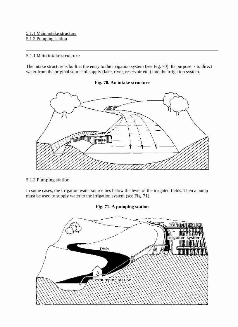
5.1.1 Main intake structure
The intake structure is built at the entry to the irrigation system (see Fig. 70). Its purpose is to direct
water from the original source of supply (lake, river, reservoir etc.) into the irrigation system.
Fig. 70. An intake structure
5.1.2 Pumping station
In some cases, the irrigation water source lies below the level of the irrigated fields. Then a pump
must be used to supply water to the irrigation system (see Fig. 71).
Fig. 71. A pumping station

There are several types of pumps, but the most commonly used in irrigation is the centrifugal pump.
The centrifugal pump (see Fig. 72a) consists of a case in which an element, called an impeller, rotates
driven by a motor (see Fig. 72b). Water enters the case at the center, through the suction pipe. The
water is immediately caught by the rapidly rotating impeller and expelled through the discharge pipe.
Fig. 72a. Diagram of a centrifugal pump
Fig. 72b. Centrifugal pump and motor
The centrifugal pump will only operate when the case is completely filled with water.
5.2 Conveyance and distribution system
5.2.1 Open canals
5.2.2 Canal structures

The conveyance and distribution systems consist of canals transporting the water through the whole
irrigation system. Canal structures are required for the control and measurement of the water flow.
5.2.1 Open canals
An open canal, channel, or ditch, is an open waterway whose purpose is to carry water from one place
to another. Channels and canals refer to main waterways supplying water to one or more farms. Field
ditches have smaller dimensions and convey water from the farm entrance to the irrigated fields.
i. Canal characteristics
According to the shape of their cross-section, canals are called rectangular (a), triangular (b), trapezoidal (c), circular (d), parabolic (e), and irregular or natural (f) (see Fig. 73).
Fig. 73. Some examples of canal cross-sections
The most commonly used canal cross-section in irrigation and drainage, is the trapezoidal cross-
section. For the purposes of this publication, only this type of canal will be considered.
The typical cross-section of a trapezoidal canal is shown in Figure 74.
Fig. 74. A trapezoidal canal cross-section
The freeboard of the canal is the height of the bank above the highest water level anticipated. It is
required to guard against overtopping by waves or unexpected rises in the water level.

The side slope of the canal is expressed as ratio, namely the vertical distance or height to the
horizontal distance or width. For example, if the side slope of the canal has a ratio of 1:2 (one to two),
this means that the horizontal distance (w) is two times the vertical distance (h) (see Fig. 75).
Fig. 75. A side slope of 1:2 (one to two)
The bottom slope of the canal does not appear on the drawing of the cross-section but on the
longitudinal section (see Fig. 76). It is commonly expressed in percent or per mil.
Fig. 76. A bottom slope of a canal
An example of the calculation of the bottom slope of a canal is given below (see also Fig. 76):
or

ii. Earthen Canals
Earthen canals are simply dug in the ground and the bank is made up from the removed earth, as illustrated in Figure 77a.
Fig. 77a. Construction of an earthen canal
The disadvantages of earthen canals are the risk of the side slopes collapsing and the water loss due to
seepage. They also require continuous maintenance (Fig. 77b) in order to control weed growth and to
repair damage done by livestock and rodents.
Fig. 77b. Maintenance of an earthen canal
iii. Lined Canals
Earthen canals can be lined with impermeable materials to prevent excessive seepage and growth of weeds (Fig. 78).
Fig. 78. Construction of a canal lined with bricks
Lining canals is also an effective way to control canal bottom and bank erosion. The materials mostly
used for canal lining are concrete (in precast slabs or cast in place), brick or rock masonry and
asphaltic concrete (a mixture of sand, gravel and asphalt).
The construction cost is much higher than for earthen canals. Maintenance is reduced for lined canals,
but skilled labour is requi

3. Describe Open wells and its types. (M/J 16)
Open Well:
To tap the groundwater storage vertical hole of bigger diameter (2 to 10 metres
generally) is some time dug or sunk in the rock or soil mass. The hole is sunk till it penetrates
saturated underground material. The hole is further taken down to reach a depth quite below
ground water-table. The depth of well or hole below the ground water-table should be such that
even during a dry year there will be sufficient depth 3 to 4 metres) of water to cope up with the
requirements then. The water surface in the well and free surface of water in the soil are at
atmospheric pressure.
Types of Open Wells:
Depending upon the type of protection provided to the sides of the wells, first
classification of open wells may be:
i. Wells with pervious lining and
ii. Wells with water-tight lining
i. Wells with Pervious Lining:
In this type, the wells are lined with dry bricks or stone masonary. Water contribution
to the well takes place through the sides. This type is very suitable when subsoil is formed of
gravel or coarse sand deposits. When the subsoil consists of sand layers, along with the seeping
water sand also comes in the well through pervious lining.
As a result hollow space is formed behind the wall lining. To check development of
such hollow formation, brick ballast of about 20 mm size is packed behind the lining at least
up to the ground water-table from the bottom. Figure 17.1 shows the typical cross-section of a
well with pervious lining.
To make the construction stable following procedure can be adopted. Construct 1.25 m
of lining just above the curb in mortar and give about 1 m thick concrete plug in the bottom.

Lining up to the ground water-table is laid dry but with 0.3 m strip of lining in mortar after
every 1.25 m of dry lining. Above the ground water-table construct the lining in mortar upto
the top. When the rate of water withdrawal is not more, this type is very economical and
lasting.
2. Wells with Impervious or Pucca (Permanent) Lining:
In regions with alluvial soil formation this type is mostly adopted. Once constructed, it
forms a permanent source of water as long as ground water conditions remain favourable. This
type is very suitable for irrigation purposes. The wells with impervious lining are deeper than the
well with previous lining. In this type the depth should not exceed 30 m for efficient working.
(Fig. 17.2).
If the well is dug deeper than 30 m then lifting of water becomes uneconomical. The
well lining is set in lime mortar or cement mortar. Sometimes the well may meet some clay
layer of small thickness. Then the well may be founded on it and a bore may be drilled to tap
underlying water bearing stratum. Such an arrangement helps in keeping the depth of wells

within specified limits. The thickness of steening wall varies from 0.3 to 0.7 m. Table 17.1
shows suitable thickness for various depths.
4. What are the components of a culvert? Illustrate. (M/J 16)
What is a Culvert?
Culvert is a tunnel structure constructed under roadways or railways to provide cross
drainage or to take electrical or other cables from one side to other. The culvert system is
totally enclosed by soil or ground.
Materials for Culvert Construction
Culverts are like pipes but very large in size. They are made of many materials like
Concrete
Steel
Plastic
Aluminum
high density polyethylene
In most cases concrete culverts are preferred. Concrete culverts may be reinforced or
non-reinforced. In some cases culverts are constructed in site called cast in situ culverts.
Precast culverts are also available. By the combination above materials we can also get
composite culvert types.
Location of Culverts
The location of culverts should be based on economy and usage. Generally it is
recommended that the provision of culverts under roadway or railway are economical. There
is no need to construct separate embankment or anything for providing culverts. The provide
culverts should be perpendicular to the roadway. The culverts should be of greater
dimensions to allow maximum water level. The culvert should be located in such a way that
flow should be easily done. It is possible by providing required gradient.

Types of Culverts
Following are the types of culverts generally used in construction:
Pipe culvert ( single or multiple)
Pipe Arch ( single or multiple)
Box culvert ( single or multiple)
Arch culvert
Bridge culvert
Pipe Culvert (Single or Multiple)
Pipe culverts are widely used culverts and rounded in shape. The culverts may be of
single in number or multiple. If single pipe culvert is used then larger diameter culvert is
installed. If the width of channel is greater than we will go for multiple pipe culverts. They are
suitable for larger flows very well. The diameter of pipe culverts ranges from 1 meter to 6m.
These are made of concrete or steel etc..
Pipe Arch Culvert (Single or Multiple)
Pipe arch culverts means nothing but they looks like half circle shaped culverts. Pipe arch
culverts are suitable for larger water flows but the flow should be stable. Because of arch shape
fishes or sewage in the drainage easily carried to the outlet without stocking at the inlet or bottom

of channel. This type of culverts can also be provided in multiple numbers based on the
requirement. They also enhance beautiful appearance.
Box Culvert (Single or Multiple)
Box culverts are in rectangular shape and generally constructed by concrete.
Reinforcement is also provided in the construction of box culvert. These are used to dispose rain
water. So, these are not useful in the dry period. They can also be used as passages to cross the
rail or roadway during dry periods for animals etc. Because of sharp corners these are not suitable
for larger velocity. Box culverts can also be provided in multiple numbers.

Arch Culvert
Arch culvert is similar to pipe arch culvert but in this case an artificial floor is provided
below the arch. For narrow passages it is widely used. The artificial floor is made of concrete
and arch also made of concrete. Steel arch culverts are also available but very expensive.
Bridge Culvert
Bridge culverts are provided on canals or rivers and also used as road bridges for vehicles. For
this culverts a foundation is laid under the ground surface. A series of culverts are laid and pavement
surface is laid on top this series of culverts. Generally these are rectangular shaped culverts these can
replace the box culverts if artificial floor is not necessary.
5. Prepare a detailed estimate of a Septic tank with dispersion trench and calculate the quantities


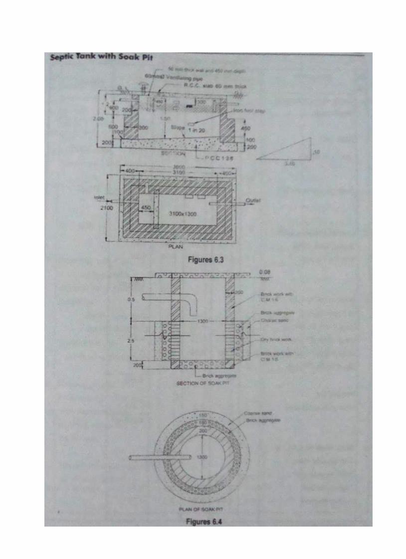
6. Prepare a detailed estimate of a septic tank with soak pit and calculate the quantities for.


7. Explain in detail about sanitary fittings and its types and usages.


8. Explain about Tube well and Open well in detail.


9. Prepare a detail estimate for the construction of a highway for 1 km length for the given fig. below.