Ccna PPT2
128
1
-
Upload
airtel -
Category
Engineering
-
view
255 -
download
0
Transcript of Ccna PPT2

1

2
Cisco IOS
Cisco technology is built around the CiscoInternetwork Operating System (IOS), which is thesoftware that controls the routing and switchingfunctions of internetworking devices.
A solid understanding of the IOS is essential for anetwork administrator.

3
The Purpose of Cisco IOS
As with a computer, a router or switch cannot function without anoperating system. Cisco calls its operating system the Cisco InternetworkOperating System or Cisco IOS.

4
Introduction to Routers
A router is a special type of computer. It has the same basic components as a standard desktopPC. However, routers are designed to perform some very specific functions. Just as computersneed operating systems to run software applications, routers need the Internetwork OperatingSystem software (IOS) to run configuration files. These configuration files contain theinstructions and parameters that control the flow of traffic in and out of the routers. The manyparts of a router are shown below:
5
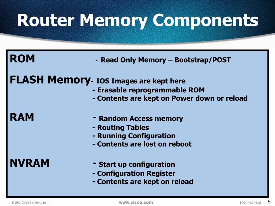
Router Memory Components
ROM - Read Only Memory – Bootstrap/POST
FLASH Memory- IOS Images are kept here
- Erasable reprogrammable ROM- Contents are kept on Power down or reload
RAM - Random Access memory
- Routing Tables- Running Configuration- Contents are lost on reboot
NVRAM - Start up configuration
- Configuration Register- Contents are kept on reload
6
ROM
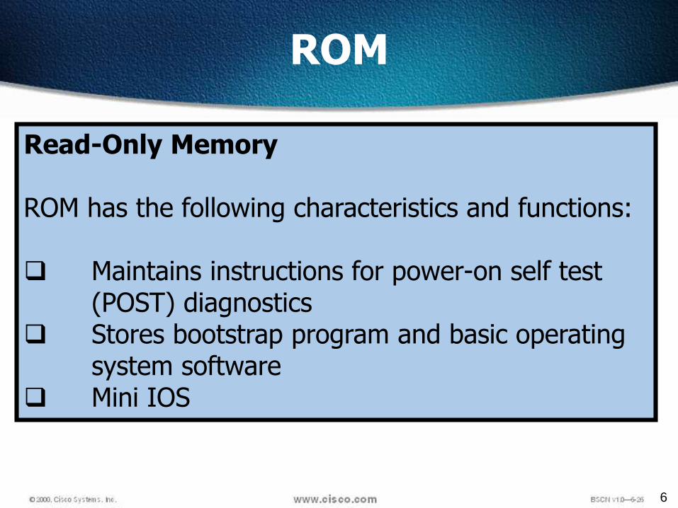
Read-Only Memory
ROM has the following characteristics and functions:
Maintains instructions for power-on self test (POST) diagnostics
Stores bootstrap program and basic operating system software
Mini IOS

7
RAM
Random Access Memory, also called dynamic RAM (DRAM)
RAM has the following characteristics and functions:
Stores routing tables Holds ARP cache Performs packet buffering (shared RAM) Provides temporary memory for the configuration file of
the router while the router is powered on Loses content when router is powered down or restarted

8
NVRAM
Non-Volatile RAM
NVRAM has the following characteristics and functions:
Provides storage for the startup configuration fileRetains content when router is powered down or
restartedConfiguration Register – 16 bit register which decidesboot sequence

9
Flash
Flash memory has the following characteristics and functions:
Holds the operating system image (IOS) Allows software to be updated without
removing and replacing chips on the processor Retains content when router is powered down
or restarted Can store multiple versions of IOS software Is a type of electronically erasable,
programmable ROM (EEPROM)
10
Interfaces
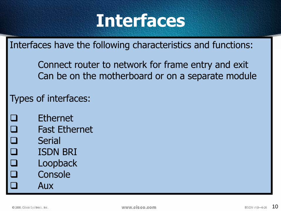
Interfaces have the following characteristics and functions:
Connect router to network for frame entry and exit Can be on the motherboard or on a separate module
Types of interfaces:
Ethernet Fast Ethernet Serial ISDN BRI Loopback Console Aux
11
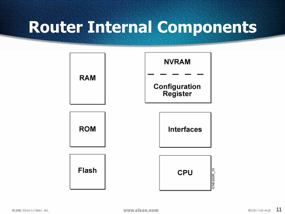
Router Internal Components
12
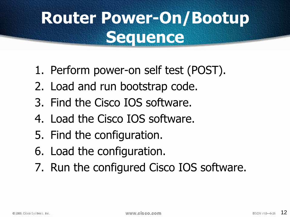
Router Power-On/Bootup Sequence
1. Perform power-on self test (POST).
2. Load and run bootstrap code.
3. Find the Cisco IOS software.
4. Load the Cisco IOS software.
5. Find the configuration.
6. Load the configuration.
7. Run the configured Cisco IOS software.

13
Boot Sequence
ROMMonitorRXBootFLASH
Configuration Register
C-File NVRAM
Y
N
Running
Setup Mode
Checks All interfaces
RAM
1415 13 12 1011 9 8 67 5 4 23 1 0
48 2 1 48 2 1 48 2 1 48 2 1
0 0 0 0
0 0 0 1
0 0 1 0
ROMMonitor
RxBoot
Flash1 1 1 1
0
1
2-15

14
After the Post…
After the POST, the following events occur as the router initializes:
Step 1The generic bootstrap loader in ROM executes. A bootstrap is a simple set of instructions thattests hardware and initializes the IOS for operation.
Step 2The IOS can be found in several places. The boot field of the configuration register determinesthe location to be used in loading the IOS.
Step 3The operating system image is loaded.
Step 4The configuration file saved in NVRAM is loaded into main memory and executed one line at atime. The configuration commands start routing processes, supply addresses for interfaces,and define other operating characteristics of the router.
Step 5If no valid configuration file exists in NVRAM, the operating system searches for an availableTFTP server. If no TFTP server is found, the setup dialog is initiated.

15
Loading the Cisco IOS Software From Flash Memory
• The flash memory file is decompressed into RAM.

16
Loading the Configuration
• Load and execute the configuration from NVRAM.
• If no configuration is present in NVRAM, enter setup mode.

17
External Components of a 2600 Router

18
Internal Components of a 2600 Router

19
Computer/Terminal Console Connection

21
HyperTerminal Session Properties
22
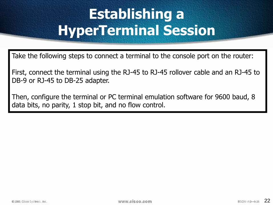
Establishing aHyperTerminal Session
Take the following steps to connect a terminal to the console port on the router:
First, connect the terminal using the RJ-45 to RJ-45 rollover cable and an RJ-45 to DB-9 or RJ-45 to DB-25 adapter.
Then, configure the terminal or PC terminal emulation software for 9600 baud, 8 data bits, no parity, 1 stop bit, and no flow control.
23
Router Command Line Interface

24
IOS File System Overview

25
Router LED Indicators
Cisco routers use LED indicators to provide status information. Dependingupon the Cisco router model, the LED indicators will vary. An interface LEDindicates the activity of the corresponding interface. If an LED is off whenthe interface is active and the interface is correctly connected, a problemmay be indicated. If an interface is extremely busy, its LED will always beon. The green OK LED to the right of the AUX port will be on after thesystem initializes correctly.

26

27
Router User Interface Modes
The Cisco command-line interface (CLI) uses a hierarchical structure. This structurerequires entry into different modes to accomplish particular tasks.
Each configuration mode is indicated with a distinctive prompt and allows onlycommands that are appropriate for that mode.
As a security feature the Cisco IOS software separates sessions into two accesslevels, user EXEC mode and privileged EXEC mode. The privileged EXEC mode is
also known as enable mode.

28
Overview of Router Modes

29
Router Modes

30
CLI Command Modes
All command-line interface (CLI) configuration changes to a Cisco router are made from the global configuration mode. Other more specific modes are entered depending upon the configuration change that is required.
Global configuration mode commands are used in a router to apply configuration statements that affect the system as a whole.
The following command moves the router into global configuration mode
Router#configure terminal (or config t)Router(config)#
When specific configuration modes are entered, the router prompt changes to indicate the current configuration mode.
Typing exit from one of these specific configuration modes will return the router to global configuration mode. Pressing Ctrl-Z returns the router to all the way back privileged EXEC mode.

31
Show Version Command
wg_ro_a#show version
Cisco Internetwork Operating System Software
IOS (tm) 2500 Software (C2500-JS-L), Version 12.0(3), RELEASE SOFTWARE (fc1)
Copyright (c) 1986-1999 by cisco Systems, Inc.
Compiled Mon 08-Feb-99 18:18 by phanguye
Image text-base: 0x03050C84, data-base: 0x00001000
ROM: System Bootstrap, Version 11.0(10c), SOFTWARE
BOOTFLASH: 3000 Bootstrap Software (IGS-BOOT-R), Version 11.0(10c), RELEASE SOFTWARE(fc1)
wg_ro_a uptime is 20 minutes
System restarted by reload
System image file is "flash:c2500-js-l_120-3.bin"
(output omitted)
--More--
Configuration register is 0x2102

32
Viewing the Configuration
33
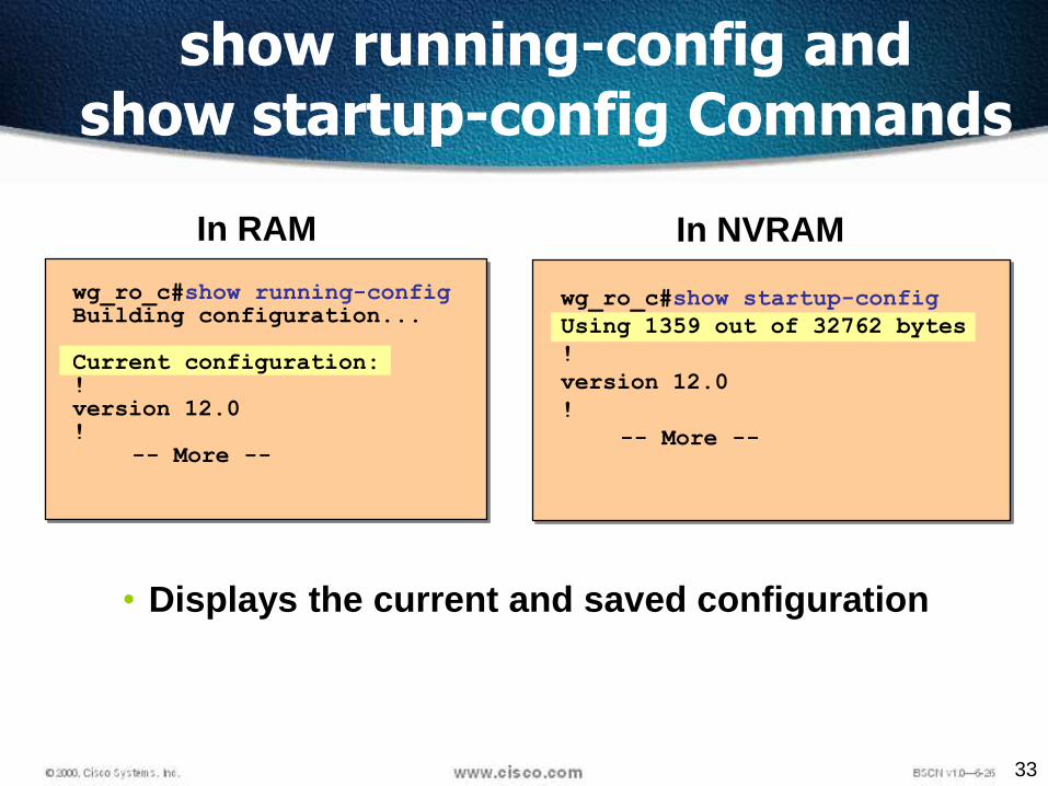
show running-config and show startup-config Commands
wg_ro_c#show startup-config
Using 1359 out of 32762 bytes
!
version 12.0
!
-- More --
wg_ro_c#show running-configBuilding configuration...
Current configuration:!version 12.0!
-- More --
In NVRAMIn RAM
• Displays the current and saved configuration

34
Configurations in two locations - RAM and NVRAM.
•The running configuration is stored in RAM.•Any configuration changes to the router are made to therunning-configuration and take effect immediately after thecommand is entered.•The startup-configuration is saved in NVRAM and is loaded intothe router's running-configuration when the router boots up.• To save the running-configuration to the startup configuration,type the following from privileged EXEC mode (i.e. at the"Router#" prompt.)
Router# copy run start
Saving Configurations

35
Command Abbreviation
Show Configuration – sh conf
Configure Terminal – conf t
Line auxillary – line aux
Line console – line con

36
Configuring a Router’s Name
A router should be given a unique name as one of the firstconfiguration tasks.
This task is accomplished in global configuration mode usingthe following commands:
Router(config)#hostname GatesGates(config)#
As soon as the Enter key is pressed, the prompt changes fromthe default host name (Router) to the newly configured hostname (which is Gates in the example above).

37
Settingthe Clockwith Help

38
Message Of The Day (MOTD)
A message-of-the-day (MOTD) banner can be displayed on all
connected terminals.
Enter global configuration mode by using the command config t
Enter the command
banner motd # Welcome to Gates Training #.
Save changes by issuing the command copy run start

39
Privileged Mode Command
# show startup-config
# show running-config
# show version
# show flash
# show interfaces
# show interfaces s 0
# show history
# show terminal
# terminal history size 25

40
Password
Passwords restrict access to routers. Passwords should always be configured for virtual terminal lines and the console line. Passwords are also used to control access to privileged EXEC mode so that only authorized users may make changes to the configuration file.

41
Passwords
There are five passwords for Router
Privileged Mode Password – 2
Line Console Password
Auxiliary Port Password
Telnet Password
42
Privileged Mode Password
Gates(config)# enable password gates
Encrypted privilege mode password
Gates(config)# enable secret gates1

43
Line Password
Gates(config)# line console 0
Gates(config)# password cisco
Gates(config)# login

44
Aux Port Password
Gates(config)# line aux 0
Gates(config)# password cisco
Gates(config)# login

45
Connecting to Aux Port

46
Configuring a Telnet Password
A password must be set on one or more of the virtualterminal (VTY) lines for users to gain remote access to therouter using Telnet.
Typically Cisco routers support five VTY lines numbered 0through 4.
47
Telnet Password
Gates(config)# line vty 0 4
Gates(config)# password cisco
Gates(config)# login

48
Encrypting Passwords
Only the enable secret password is encrypted by default
Need to manually configure the user-mode and enablepasswords for encryption
To manually encrypt your passwords, use the servicepassword-encryption command
Router#config t
Enter configuration commands, one per line. End with CNTL/Z.
Router(config)#service password-encryption

49
Disable Passwords
Gates(config)# no enable password
Gates(config)# no enable secret
For the Console
Gates(config)# line con 0
Gates(config)# no password
Gates(config)# line vty 0 4
Gates(config)# no password
50
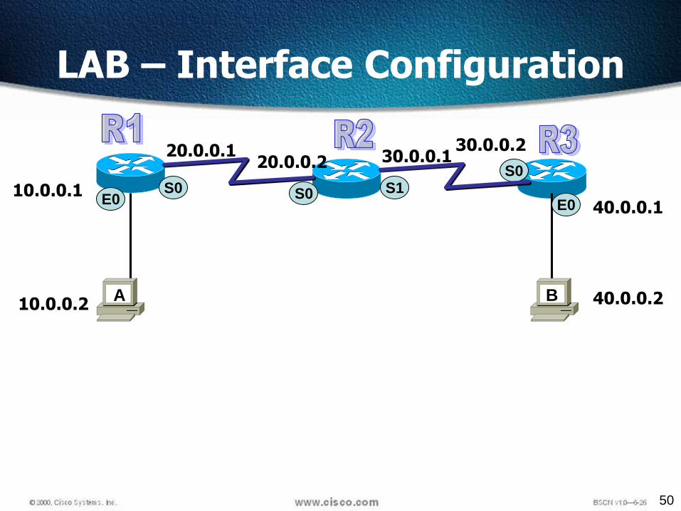
LAB – Interface Configuration
S0 S0E010.0.0.1
10.0.0.2
30.0.0.220.0.0.120.0.0.2 30.0.0.1
A
S0
E0
40.0.0.2
40.0.0.1
B
S1

51
Descriptions
Setting descriptions on an interface is helpful to the administrator
Only locally significant
R1(config)#int e0
R1(config-if)#description Sales Lan
R1(config-if)#int s0
R1(config-if)#desc Wan to Mumbai

52
Configuring Interfaces
An interface needs an IP Address and a Subnet Mask to be configured. All interfaces are “shutdown” by default. The DCE end of a serial interface needs a clock rate.R1#config t
R1(config)#int e0
R1(config)#Description Connoted to Host
R1(config-if)#ip address 10.0.0.1 255.0.0.0
R1(config-if)#no shutdown
R1(config-if)#exitR1(config)#interface serial 0R1(config-if)#ip address 20.0.0.1 255.255.255.0
R1(config-if)# bandwidth 64R1(config-if)#clock rate 64000 (required for serial DCE only) R1(config-if)#no shutdownR1(config-if)#exitR1(config)#exitR1#
On new routers, Serial 1 would be just Serial 0/1 and e0 would be f0/0.
s = serial e = Ethernet f = fast Ethernet
53
DCE DTE
To find out DCE or DTE
#Show controllers s 0
54
Viewing Configuration
To Check the status of interface
#Show IP interface brief
or
#Sh IP int brief

55
Saving and Erasing Configurations
To copy RAM to NVRAM
# copy run startup-config
To remove all configuration
# erase startup-config
# reload

56
57
Objectives
Upon completion of this chapter, you will be able to complete the following tasks:
Distinguish the use and operation of static and dynamic routes
Configure and verify a static route
Identify how distance vector IP routing protocols such as RIP and IGRP operate on Cisco routers
Enable Routing Information Protocol (RIP)
Enable Interior Gateway Routing Protocol (IGRP)
Verify IP routing with show and debug commands

58
Routing
The process of transferring data from one local areanetwork to another
Layer 3 devicesRouted protocol Enables to forward packet from one
router to another – Ex – IP, IPXRouting protocol sends and receives routing
information packets to and from other routers – Ex -RIP, OSPF , IGRP
Routing protocols gather and share the routinginformation used to maintain and update routingtables.
That routing information is in turn used to route arouted protocol to its final destination
59
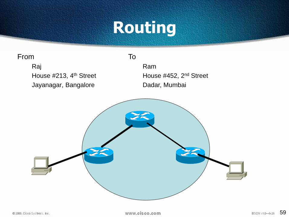
Routing
From
Raj
House #213, 4th Street
Jayanagar, Bangalore
To
Ram
House #452, 2nd Street
Dadar, Mumbai
60
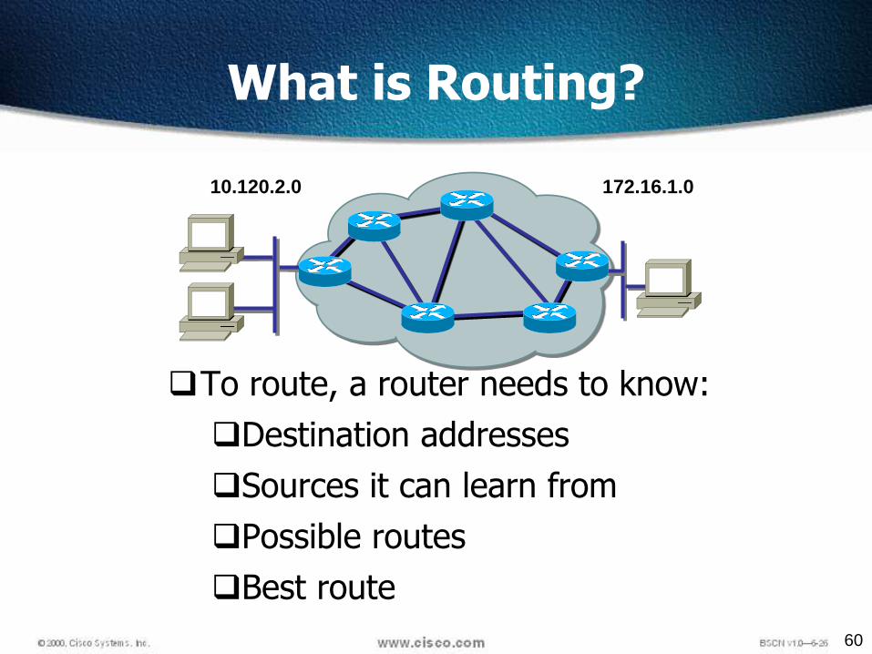
To route, a router needs to know:
Destination addresses
Sources it can learn from
Possible routes
Best route
What is Routing?
172.16.1.010.120.2.0

61
What is Routing? (cont.)
NetworkProtocol
DestinationNetwork
ConnectedLearned
10.120.2.0172.16.1.0
Exit Interface
E0S0
Routed Protocol: IP
Routers must learn destinations that are not directly connected
172.16.1.010.120.2.0
E0S0

62
Route Types
Static routing - network administrator configuresinformation about remote networks manually. They areused to reduce overhead and for security.
Dynamic routing - information is learned from otherrouters, and routing protocols adjust routesautomatically.
Because of the extra administrative requirements, staticrouting does not have the scalability of dynamic routing.
63
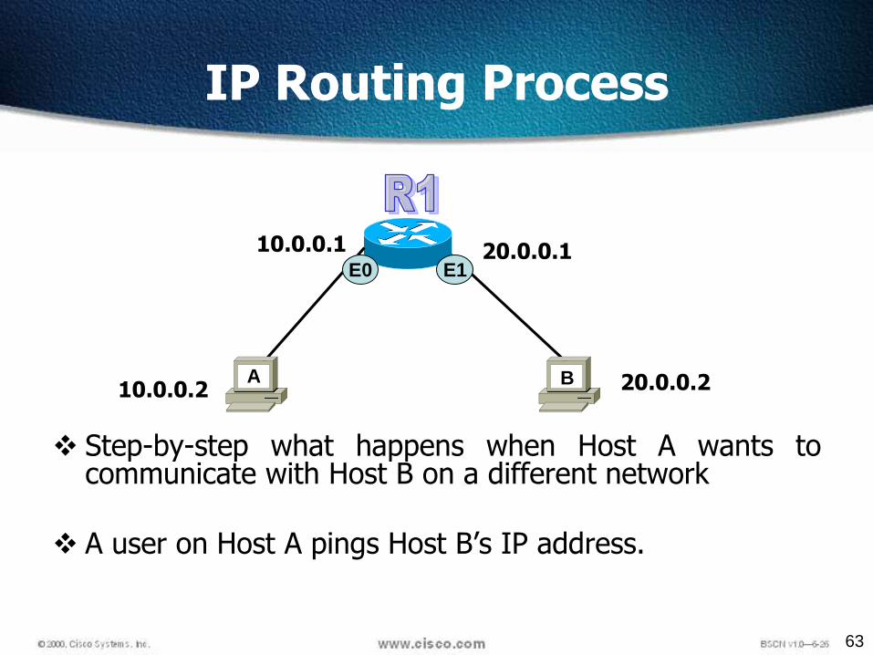
IP Routing Process
Step-by-step what happens when Host A wants tocommunicate with Host B on a different network
A user on Host A pings Host B’s IP address.
E0 E1
10.0.0.1
10.0.0.2A B 20.0.0.2
20.0.0.1

65
LAB – Interface Configuration
S0 S0E010.0.0.1
10.0.0.2
30.0.0.220.0.0.120.0.0.2 30.0.0.1
A
S0
E0
40.0.0.2
40.0.0.1
B
S1

66
Test The Connection
• Host A can ping router R1 and R2
• To enable Host A to Ping Host B we need to configure Routes

67
IP Routing
The different types of routing are:
Static routing
Default routing
Dynamic routing
68
Static Routes
Benefits
No overhead on the router CPU
No bandwidth usage between routers
Adds security
Disadvantage
Administrator must really understand the internetwork
If a network is added to the internetwork, the
administrator has to add a route to it on all routers
Not feasible in large networks

69
– R1(config)# iproute DestAddress SNM Nexthop address
R1(config)#ip route network [mask] {address | interface}[distance] [permanent]
Static Route Configuration
70
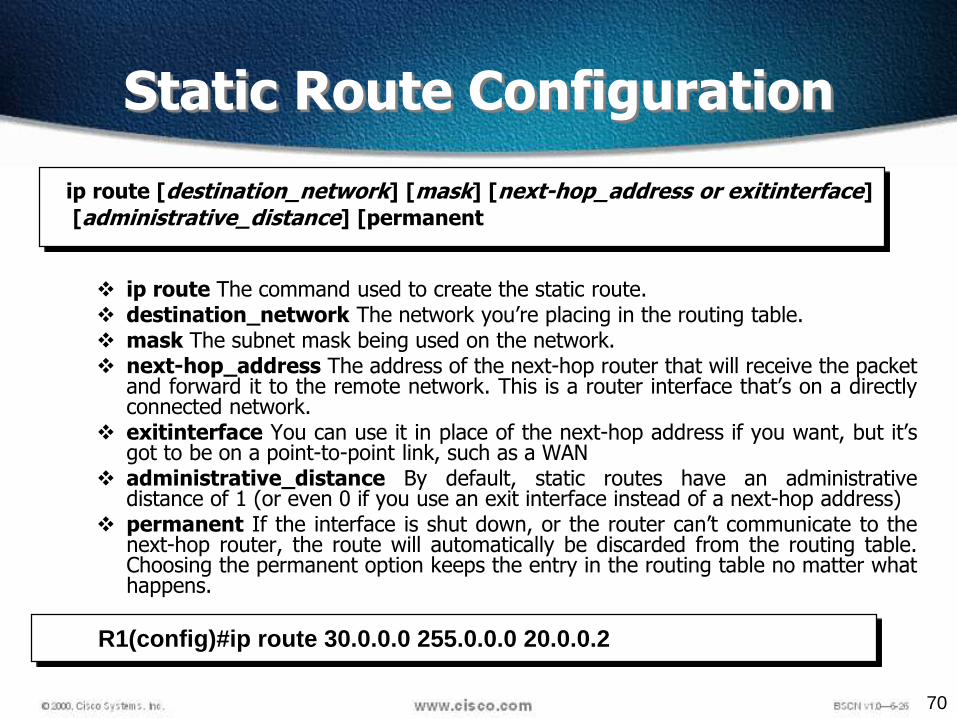
ip route The command used to create the static route. destination_network The network you’re placing in the routing table. mask The subnet mask being used on the network. next-hop_address The address of the next-hop router that will receive the packet
and forward it to the remote network. This is a router interface that’s on a directlyconnected network.
exitinterface You can use it in place of the next-hop address if you want, but it’sgot to be on a point-to-point link, such as a WAN
administrative_distance By default, static routes have an administrativedistance of 1 (or even 0 if you use an exit interface instead of a next-hop address)
permanent If the interface is shut down, or the router can’t communicate to thenext-hop router, the route will automatically be discarded from the routing table.Choosing the permanent option keeps the entry in the routing table no matter whathappens.
ip route [destination_network] [mask] [next-hop_address or exitinterface]
[administrative_distance] [permanent
Static Route Configuration
R1(config)#ip route 30.0.0.0 255.0.0.0 20.0.0.2
71
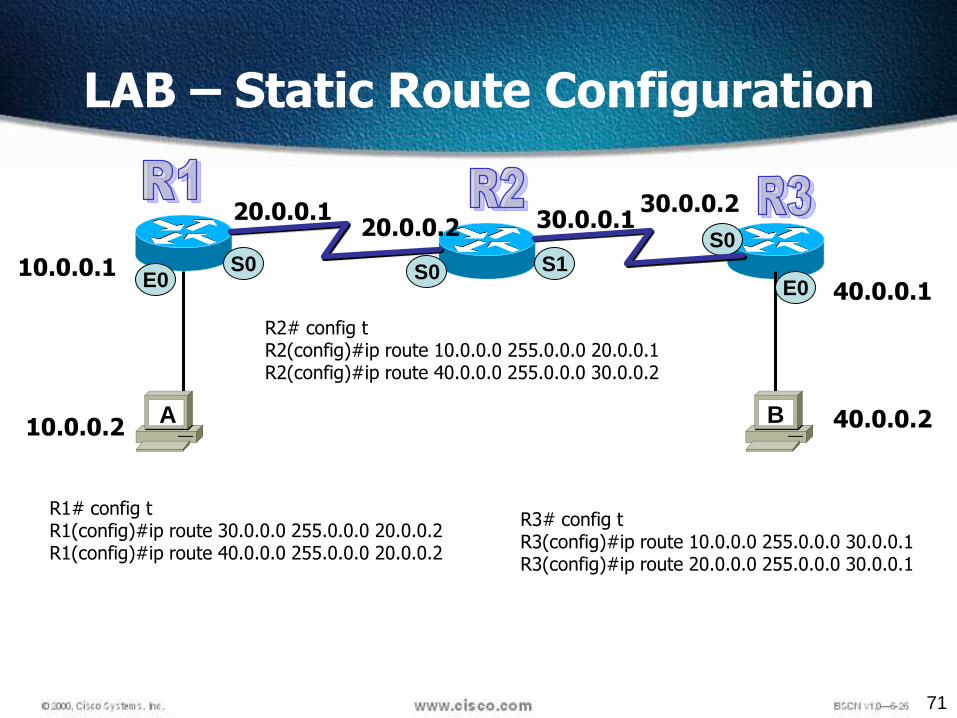
LAB – Static Route Configuration
S0 S0E010.0.0.1
10.0.0.2
30.0.0.220.0.0.120.0.0.2 30.0.0.1
A
S0
E0
40.0.0.2
40.0.0.1
B
S1
R1# config tR1(config)#ip route 30.0.0.0 255.0.0.0 20.0.0.2R1(config)#ip route 40.0.0.0 255.0.0.0 20.0.0.2
R2# config tR2(config)#ip route 10.0.0.0 255.0.0.0 20.0.0.1R2(config)#ip route 40.0.0.0 255.0.0.0 30.0.0.2
R3# config tR3(config)#ip route 10.0.0.0 255.0.0.0 30.0.0.1R3(config)#ip route 20.0.0.0 255.0.0.0 30.0.0.1

72
Verifying StaticRoute Configuration
After static routes are configured it is important to verify thatthey are present in the routing table and that routing isworking as expected.
The command show running-config is used to view theactive configuration in RAM to verify that the static route wasentered correctly.
The show ip route command is used to make sure that thestatic route is present in the routing table.

73
S0 S0E010.0.0.1
10.0.0.2
30.0.0.220.0.0.120.0.0.2 30.0.0.1
A
S0
E0
40.0.0.2
40.0.0.1
B
S1
R1# config tR1(config)#no ip route 30.0.0.0 255.0.0.0 20.0.0.2R1(config)#no ip route 40.0.0.0 255.0.0.0 20.0.0.2
R2# config tR2(config)#no ip route 10.0.0.0 255.0.0.0 20.0.0.1R2(config)#no ip route 40.0.0.0 255.0.0.0 30.0.0.2
R3# config tR3(config)#no ip route 10.0.0.0 255.0.0.0 30.0.0.1R3(config)#no ip route 20.0.0.0 255.0.0.0 30.0.0.1
Removing IP Route

74
Default Routes
• Can only use default routing on stub networks
• Stub networks are those with only one exit path out ofthe network
• The only routers that are considered to be in a stubnetwork are R1 and R3
S0S0E0
E010.0.0.1
10.0.0.2 40.0.0.2
20.0.0.1
20.0.0.2
30.0.0.1
A B
S0S1
30.0.0.2
40.0.0.1
75
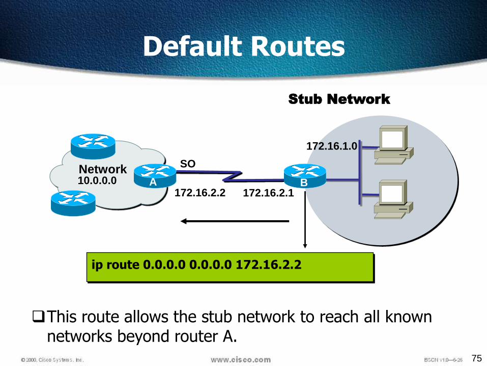
Stub Network
ip route 0.0.0.0 0.0.0.0 172.16.2.2
Default Routes
172.16.2.1
SO
172.16.1.0
B172.16.2.2
NetworkA B
This route allows the stub network to reach all known networks beyond router A.
10.0.0.0

76
Configuring Default Routes
Default routes are used to route packets with destinations that do not match any of the other routes in the routing table.
A default route is actually a special static route that uses this format:
ip route 0.0.0.0 0.0.0.0 [next-hop-address | outgoing interface]
This is sometimes referred to as a “Quad-Zero” route.
Example using next hop address:
Router(config)#ip route 0.0.0.0 0.0.0.0 172.16.4.1
Example using the exit interface:
Router(config)#ip route 0.0.0.0 0.0.0.0 s0/0
77
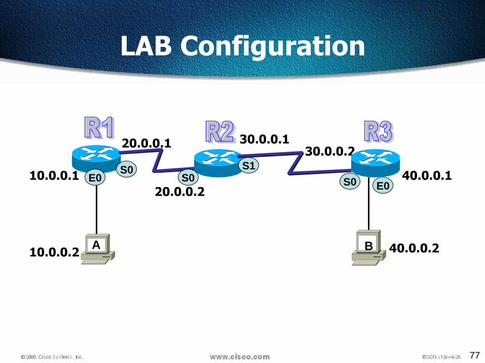
S0S0E0
E010.0.0.1
10.0.0.2 40.0.0.2
20.0.0.1
20.0.0.2
30.0.0.1
A B
S0S1
30.0.0.2
40.0.0.1
LAB Configuration

78
Default Route LAB Configuration
S0S0E0
E010.0.0.1
10.0.0.2 40.0.0.2
20.0.0.1
20.0.0.2
30.0.0.1
A B
S0S1
30.0.0.2
40.0.0.1
R1# config tR1(config)#ip route 0.0.0.0 0.0.0.0 20.0.0.2
R3# config tR3(config)#ip route 0.0.0.0 0.0.0.0 30.0.0.1
R2# config tR2(config)#ip route 10.0.0.0 255.0.0.0 20.0.0.1R2(config)#ip route 40.0.0.0 255.0.0.0 30.0.0.2

79
What is a Routing Protocol?
Routing protocols areused betweenrouters to determinepaths and maintainrouting tables.
Once the path isdetermined a router canroute a routed protocol.
NetworkProtocol
DestinationNetwork
ConnectedRIP
IGRP
10.120.2.0172.16.2.0172.17.3.0
Exit Interface
E0S0S1
Routed Protocol: IPRouting protocol: RIP, IGRP
172.17.3.0
172.16.1.010.120.2.0
E0S0

80
Autonomous System
AS 2000
AS 3000
IGP
Interior Gateway Protocols are
used for routing decisions
within an Autonomous System.
Exterior Gateway
Protocols are used
for routing between
Autonomous Systems
EGP
AS 1000
An Autonomous System (AS) is a group of IP networks, which has asingle and clearly defined routing policy.Group of routers which can exchange updatesAS are identified by numbers
Fig. 48 IGP and EGP (TI1332EU02TI_0004 The Network Layer, 67)
All Routing protocols are categorized as IGP or EGP
Routing Categories
81
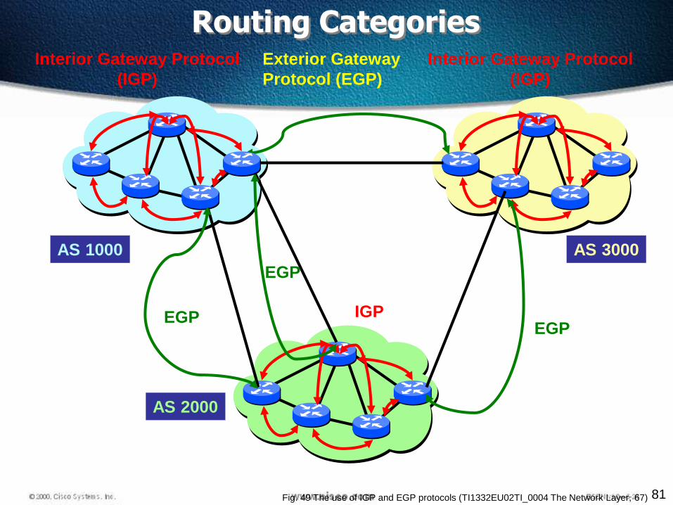
IGP
Interior Gateway Protocol
(IGP)
Exterior Gateway
Protocol (EGP)
EGP
EGP
EGP
Interior Gateway Protocol
(IGP)
AS 1000
AS 2000
AS 3000
Fig. 49 The use of IGP and EGP protocols (TI1332EU02TI_0004 The Network Layer, 67)
Routing Categories

82
An autonomous system is a collection of networks under acommon administrative domain.
IGPs operate within an autonomous system.
EGPs connect different autonomous systems.
Autonomous Systems: Interior or Exterior Routing Protocols

83
Types or Classes of Routing Protocols

84
Distance Vector
RIP V1
IGRP
RIP V2
Link state
OSPF
Hybrid
EIGRP
Types or Classes of Routing Protocols
85
Classful Routing Overview
Classful routing protocols do not include the subnet mask with theroute advertisement.
Within the same network, consistency of the subnet masks isassumed.
Summary routes are exchanged between foreign networks.
Examples of classful routing protocols:
RIP Version 1 (RIPv1)
IGRP

86
Classless Routing Overview
Classless routing protocols include the subnet mask withthe route advertisement.
Classless routing protocols support variable-lengthsubnet masking (VLSM) and subnetting
Examples of classless routing protocols:
RIP Version 2 (RIPv2)
EIGRP
OSPF
IS-IS
87
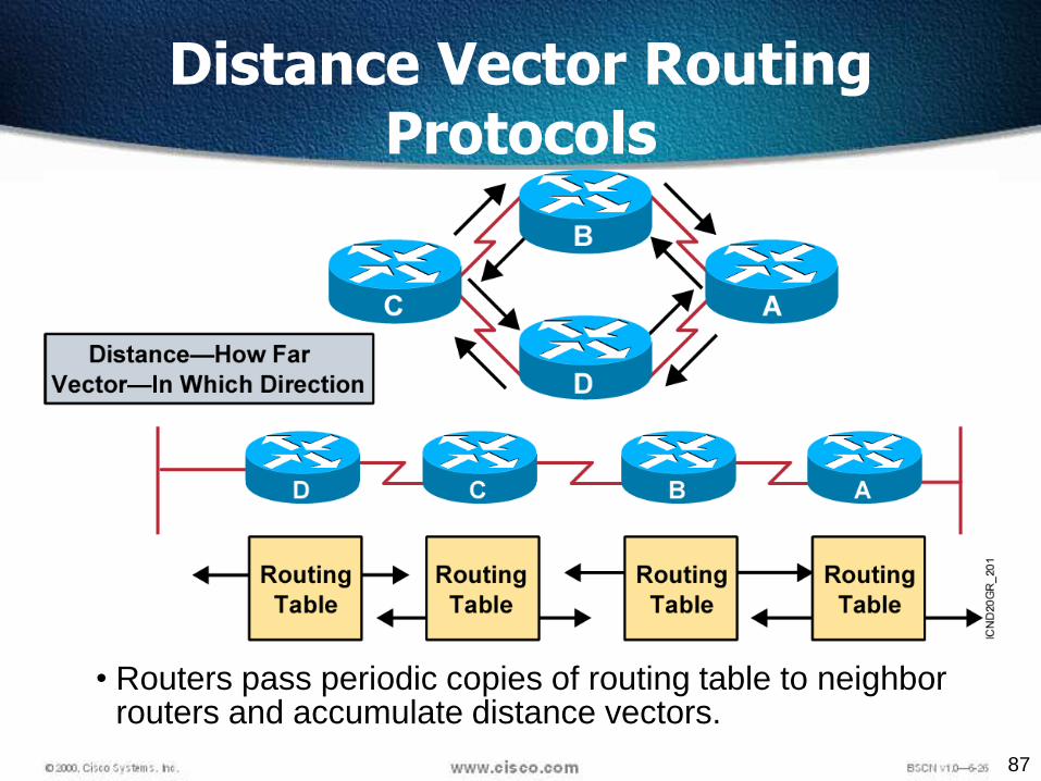
• Routers pass periodic copies of routing table to neighbor routers and accumulate distance vectors.
Distance Vector Routing Protocols

88
Distance Vector
Uses Bellman Ford Algorithm
It needs to find out the shortest path from one network to other
How to determine which path is best?
192.168.10.1192.168.20.1

89
Distance Vector
There are two Distance Vector Protocol, Both uses different metric
RIP – Hops
IGRP - Composite
192.168.10.1
192.168.20.1

90
Distance Vector
DV protocol are known as Routing by rumor RIP uses only Hop count RI routing table metric for 192.168.20.1 network will be
3 2
192.168.10.1
192.168.20.1
0
1
1
2
2
3R1
91
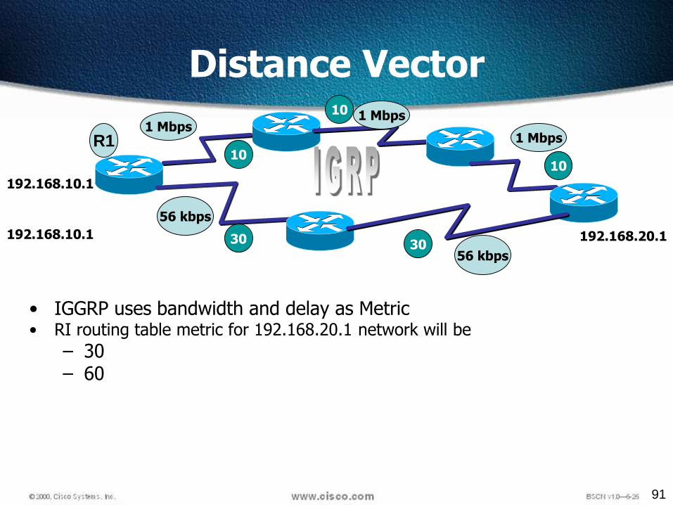
Distance Vector
192.168.10.1
192.168.20.1
56 kbps
1 Mbps1 Mbps
1 Mbps
56 kbps
• IGGRP uses bandwidth and delay as Metric• RI routing table metric for 192.168.20.1 network will be
– 30– 60
R110
10
10
30 30192.168.10.1
92
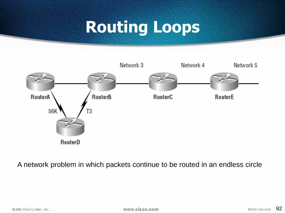
Routing Loops
A network problem in which packets continue to be routed in an endless circle

93
• Routers discover the best path to destinations from each neighbor.
Sources of Information and Discovering Routes
94
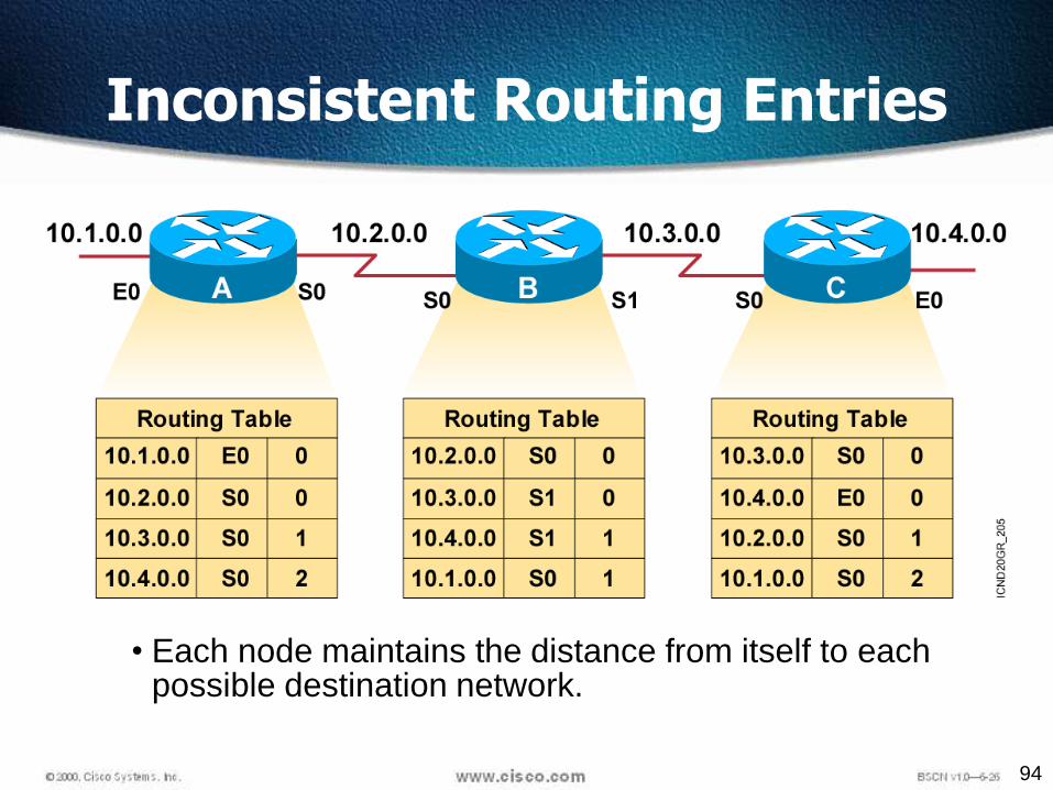
• Each node maintains the distance from itself to each possible destination network.
Inconsistent Routing Entries
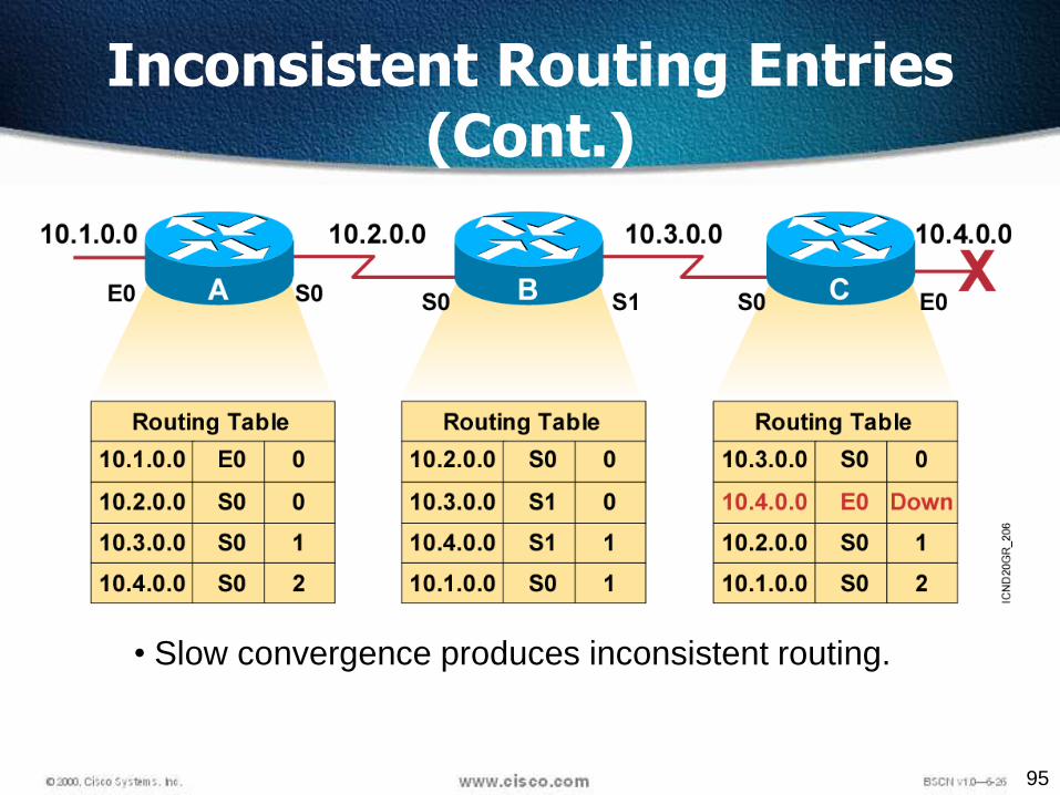
95
• Slow convergence produces inconsistent routing.
Inconsistent Routing Entries (Cont.)

96
• Router C concludes that the best path to network 10.4.0.0 is through router B.
Inconsistent Routing Entries (Cont.)

97
• Router A updates its table to reflect the new but erroneous hop count.
Inconsistent Routing Entries (Cont.)
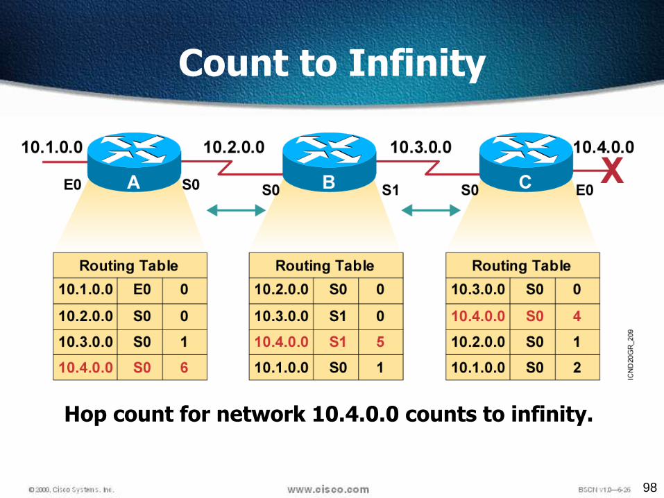
98
Hop count for network 10.4.0.0 counts to infinity.
Count to Infinity

99
• Packets for network 10.4.0.0 bounce (loop) between routers B and C.
Routing Loops

100
• Define a limit on the number of hops to prevent infinite loops.
Defining a Maximum
101
Maximum Hop Count
• One way of solving routing loop problem is to define amaximum hop count.
• RIP permits a hop count of up to 15, so anything thatrequires 16 hops is deemed unreachable
• The maximum hop count will control how long it takesfor a routing table entry to become invalid
102
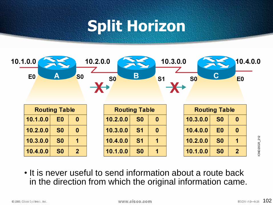
• It is never useful to send information about a route back in the direction from which the original information came.
Split Horizon

103
Split Horizon
Solution to the Routing Loop problem
Split Horizon is a rule that routinginformation cannot be sent back in thedirection from which it was received
Had split horizon been used in ourexample, Router B would not haveincluded information about network10.4.0.0 in its update to Router C.
104
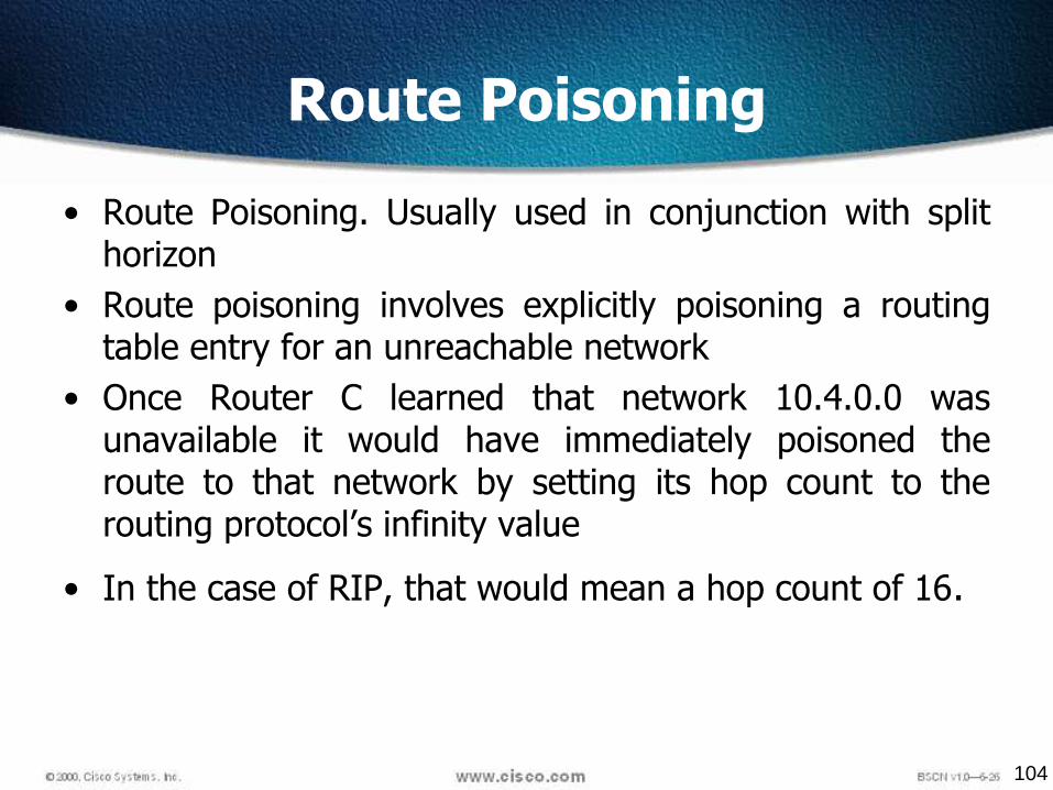
Route Poisoning
• Route Poisoning. Usually used in conjunction with splithorizon
• Route poisoning involves explicitly poisoning a routingtable entry for an unreachable network
• Once Router C learned that network 10.4.0.0 wasunavailable it would have immediately poisoned theroute to that network by setting its hop count to therouting protocol’s infinity value
• In the case of RIP, that would mean a hop count of 16.

105
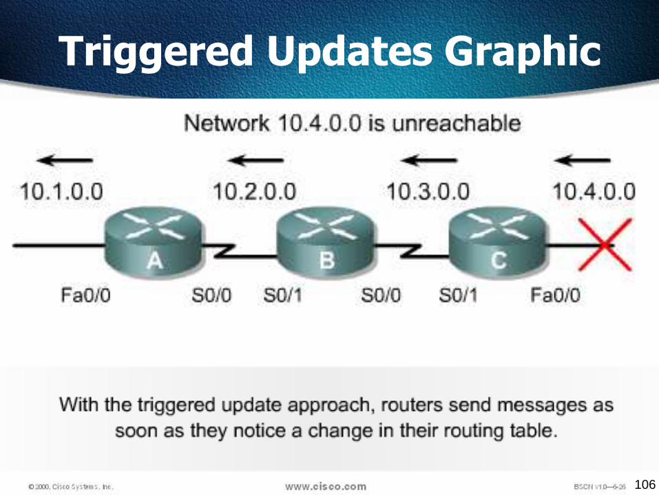
Triggered Updates
New routing tables are sent to neighboring routers on a regular basis.
RIP updates occur every 30 seconds
However a triggered update is sent immediately in response to somechange in the routing table.
The router that detects a topology change immediately sends an updatemessage to adjacent routers that, in turn, generate triggered updatesnotifying their adjacent neighbors of the change.
Triggered updates, used in conjunction with route poisoning, ensure thatall routers know of failed routes.
106
Triggered Updates Graphic

107
Holddowns
• Holddowns are a technique used to ensure that a route recentlyremoved or changed is not reinstated by a routing table updatefrom another route
• Holddown prevents regular update messages from reinstating aroute that is going up and down (called flapping)
• Holddowns prevent routes from changing too rapidly by allowingtime for either the downed route to come back up
• Holddowns make a router wait a period of time before accepting anupdate for a network whose status or metric has recently changed

108
Solution: Holddown Timers

109
Pinhole Congestion
192.168.10.1
192.168.20.1
1Mbps 1Mbps
56kbps
56kbps
110
RIP Timers
• Route update timer Sets the interval (typically 30 seconds)between periodic routing updates
• Route invalid timer Determines the length of time (180 seconds)before a router determines that a route has become invalid
• Holddown timer This sets the amount of time during whichrouting information is suppressed. This continues until either anupdate packet is received with a better metric or until the holddowntimer expires. The default is 180 seconds
• Route flush timer Sets the time between a route becoming invalidand its removal from the routing table (240 seconds).
111
Routing Information Protocol (RIP)
Routing Information Protocol (RIP) is a true distance-vector routingprotocol.
It sends the complete routing table out to all active interfaces every30 seconds
RIP only uses hop count to determine the best way to a remotenetwork
It has a maximum allowable hop count of 15 AD is 120 Bellman-ford algorithm Works well in small networks, but it’s inefficient on large networks RIP version 1 uses only classful routing, which means that all
devices in the network must use the same subnet mask RIP version 2 does send subnet mask information with the route
updates. This is called classless routing.

112
Router Configuration
The router command starts a routing process.
The network command is required because it enables therouting process to determine which interfaces participate inthe sending and receiving of routing updates.
An example of a routing configuration is:
Gates(config)#router ripGates(config-router)#network 172.16.0.0
The network numbers are based on the network classaddresses, not subnet addresses or individual host addresses.
113
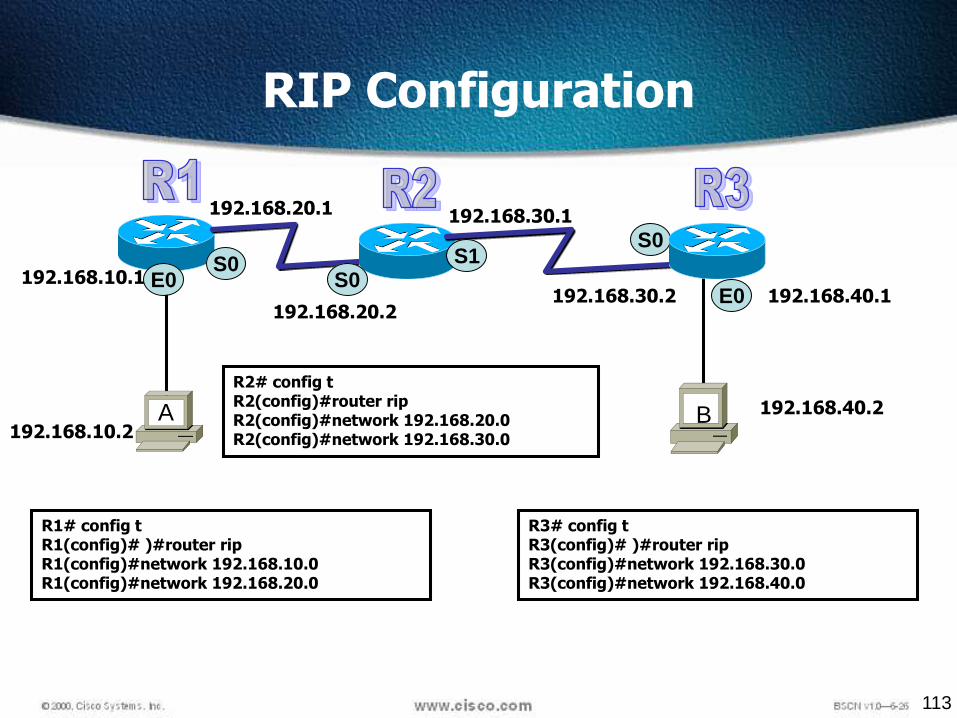
RIP Configuration
S0S0
E0E0
192.168.10.1
A B
S0S1
R1# config tR1(config)# )#router ripR1(config)#network 192.168.10.0R1(config)#network 192.168.20.0
R2# config tR2(config)#router ripR2(config)#network 192.168.20.0R2(config)#network 192.168.30.0192.168.10.2
192.168.20.1
192.168.20.2
192.168.30.1
192.168.30.2 192.168.40.1
192.168.40.2
R3# config tR3(config)# )#router ripR3(config)#network 192.168.30.0R3(config)#network 192.168.40.0

114
Verifying RIP Configuration

115
Displaying the IP Routing Table
116
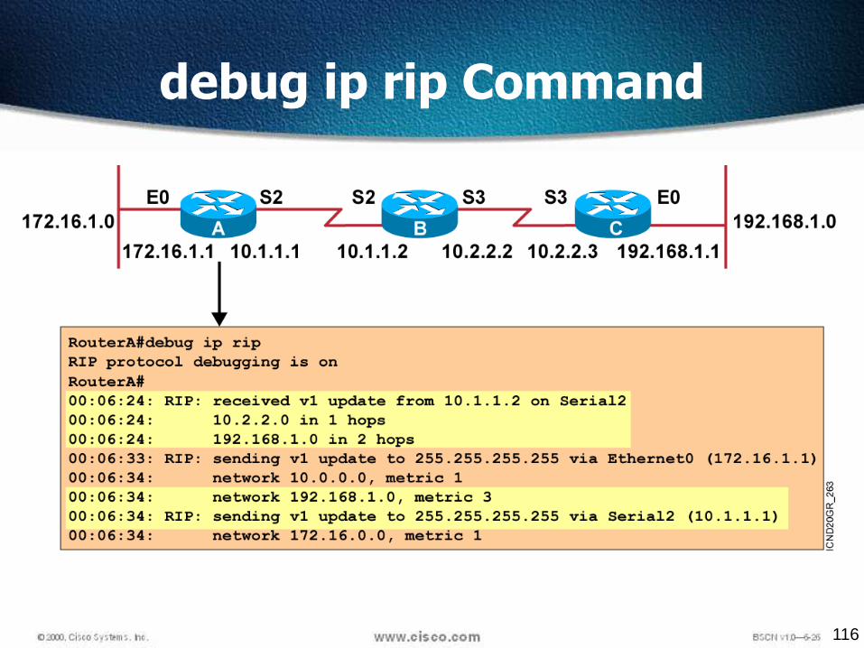
debug ip rip Command

117
Passive Interface
Passive-interface command prevents RIP updatebroadcasts from being sent out a defined interface, butsame interface can still receive RIP updates
R1#config t
R1(config)#router rip
R1(config-router)#network 192.168.10.0
R1(config-router)#passive-interface serial 0
Passive-interface command depends upon the routingprotocol
RIP router with a passive interface will still learn aboutthe networks advertised by other routers
EIGRP, a passive-interface will neither send nor receiveupdates.
118
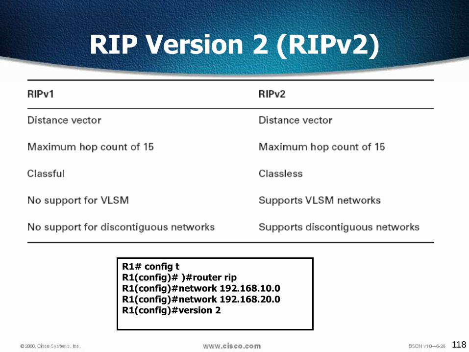
RIP Version 2 (RIPv2)
R1# config tR1(config)# )#router ripR1(config)#network 192.168.10.0R1(config)#network 192.168.20.0R1(config)#version 2
119
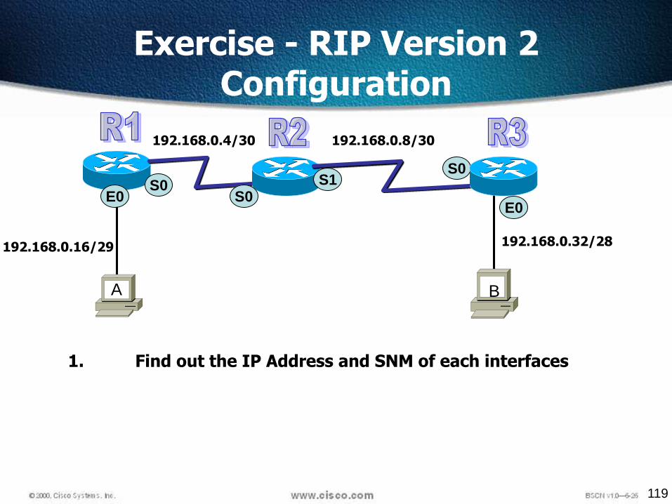
Exercise - RIP Version 2 Configuration
S0S0
E0E0
192.168.0.16/29
A B
S0S1
192.168.0.4/30 192.168.0.8/30
192.168.0.32/28
1. Find out the IP Address and SNM of each interfaces
120
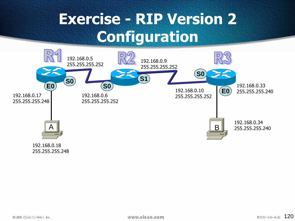
Exercise - RIP Version 2 Configuration
S0S0
E0E0
192.168.0.18255.255.255.248
A B
S0S1
192.168.0.17255.255.255.248
192.168.0.5255.255.255.252
192.168.0.6255.255.255.252
192.168.0.9255.255.255.252
192.168.0.10255.255.255.252
192.168.0.33255.255.255.240
192.168.0.34255.255.255.240

121
Exercise - RIP Version 2 Configuration
S0S0
E0E0
192.168.0.16/29
A B
S0S1
192.168.0.4/30 192.168.0.8/30
192.168.0.32/28R2# config tR2(config)#router ripR2(config)#network 192.168.0.4R2(config)#network 192.168.0.8R2(config)#version 2
R1# config tR1(config)# )#router ripR1(config)#network 192.168.0.4R1(config)#network 192.168.0.16R1(config)#version 2
R3# config tR3(config)# )#router ripR3(config)#network 192.168.0.8R3(config)#network 192.168.0.32R3(config)#version 2

122© 2002, Cisco Systems, Inc. All rights reserved. 122
Enabling IGRP

123
CISCO Proprietary
More scalable than RIP
Sophisticated metric
Introducing IGRP

124
Bandwidth
Delay
Reliability
Load
MTU
IGRP Composite Metric

125
IGRP
Some of the IGRP key design characteristics emphasize the following:
It is a distance vector routing protocol.
Routing updates are broadcast every 90 seconds.
Bandwidth, load, delay and reliability are used to create a
composite metric.
The main difference between RIP and IGRP configuration isthat when you configure IGRP, you supply the autonomoussystem number. All routers must use the same number in orderto share routing table information.

126
IGRP Vs RIP
128
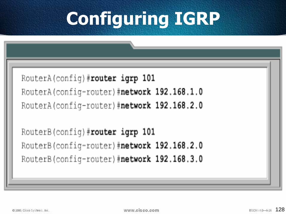
Configuring IGRP

129
IGRP Configuration
S0S0
E0E0
192.168.10.1
A B
S0S1
R1# config tR1(config)# )#router igrp 10R1(config)#network 192.168.10.0R1(config)#network 192.168.20.0
R2# config tR2(config)#router igrp 10R2(config)#network 192.168.20.0R2(config)#network 192.168.30.0192.168.10.2
192.168.20.1
192.168.20.2
192.168.30.1
192.168.30.2 192.168.40.1
192.168.40.2
R3# config tR3(config)# )#router igrp 10R3(config)#network 192.168.30.0R3(config)#network 192.168.40.0

130
Verifying the IGRP Routing Tables
LabA#sh ip route
[output cut]
I 192.168.50.0 [100/170420] via 192.168.20.2, Serial0/0
I 192.168.40.0 [100/160260] via 192.168.20.2, Serial0/0
I 192.168.30.0 [100/158360] via 192.168.20.2, Serial0/0
C 192.168.20.0 is directly connected Serial0/0
C 192.168.10.0 is directly connected, FastEthernet0/0
• The I means IGRP-injected routes. The 100 in [100/160360] is theadministrative distance of IGRP. The 160,360 is the compositemetric. The lower the composite metric, the better the route.
• To delete all routes
clear ip route

131
Debug Commands
debug ip igrp events Command
summary of the IGRP routing information that is running on the network.
debug ip igrp transactions Command
shows message requests from neighbor routers asking for an update and the broadcasts sent from your router toward that neighbor router.
no debug all – to turn off all debug